em wave diffraction - physics of magnetism and...
TRANSCRIPT

EM Wave DIffraction
Part-1

Basic Principle of Diffraction
Concept:Macroscopic: Spreading direction of wave propagations when either passing through a slit or it is blocked by a small object or it passes through a sharp edge of an object
Microscopic:How the diffraction happens:a. EM waves hitting the screen will oscillate the electrons of
the screen.b. At the equilibrium condition, the electrons will oscillate
with the same frequency as the incident wave.c. Electrons would then radiate EM waves which will
interfere with the incident wave

Basic Principle of Diffraction
d. Along with the absorption, this interference is destructive behind the screen, ZERO (0).
e. Given an aperture , the field behind the screen =0 – radiation field passing through the aperture
d. Aperture can then be modeled as a source point from which the wavelets propagates through. The interference between these wavelets is what generating the interference pattern behind the screen
Basic Principle of Diffraction
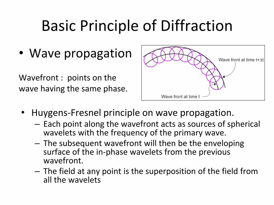
• Wave propagation
Wavefront : points on the wave having the same phase.
• Huygens-Fresnel principle on wave propagation.– Each point along the wavefront acts as sources of spherical
wavelets with the frequency of the primary wave.– The subsequent wavefront will then be the enveloping
surface of the in-phase wavelets from the previous wavefront.
– The field at any point is the superposition of the field from all the wavelets
Qualitative Aspect of Diffraction
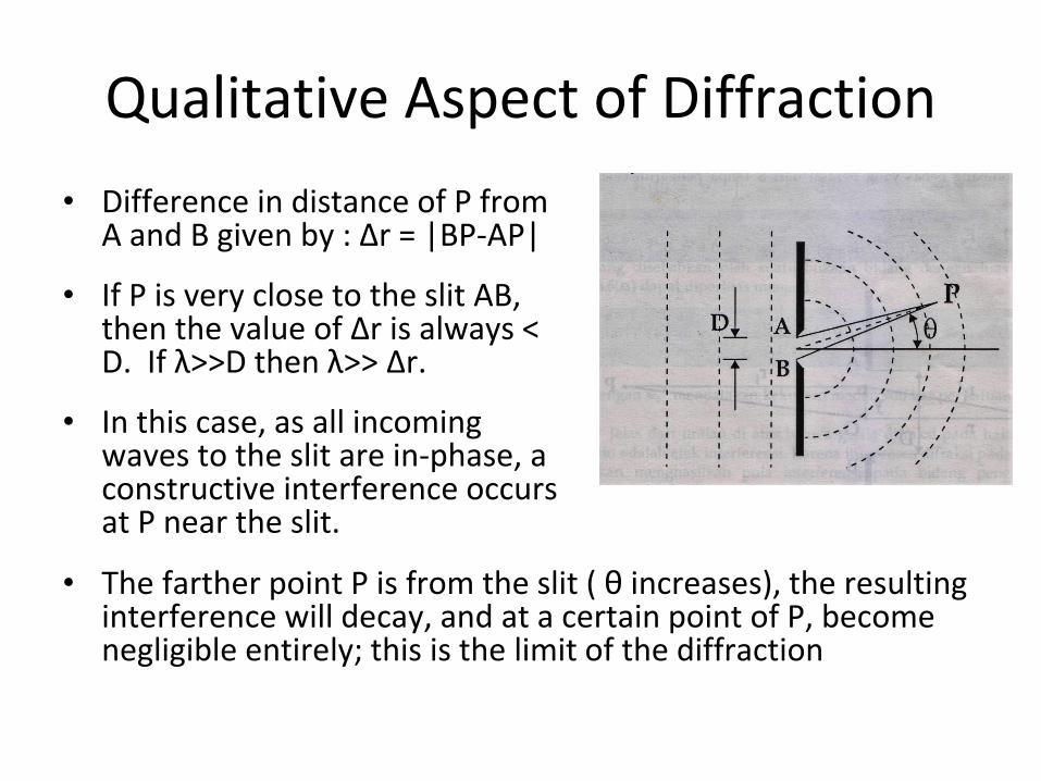
• Difference in distance of P from A and B given by : Δr = |BP-AP|
• If P is very close to the slit AB, then the value of Δr is always < D. If λ>>D then λ>> Δr.
• In this case, as all incoming waves to the slit are in-phase, a constructive interference occurs at P near the slit.
• The farther point P is from the slit ( θ increases), the resulting interference will decay, and at a certain point of P, become negligible entirely; this is the limit of the diffraction

Qualitative Aspect of Diffraction
• Conversely if λ<<D, then the interference constraint λ>> Δr, is applicable only for small θ. As such the diffraction effect is limited.
• Ergo, the relative size of D with respect to λ determines the extent of the diffraction.
D D
λ

General Formulation
• Model :
A source S producing spherical wave, and symmetrically situated in the middle of the slit AB.
– All the points within the slit are the “source” of the incoming wavelets, conversely all the points outside are not ( Fresnel approximation)
– Assume all the wavelets are equally linearly polarized (Scalar approximation)
i
General Formulation
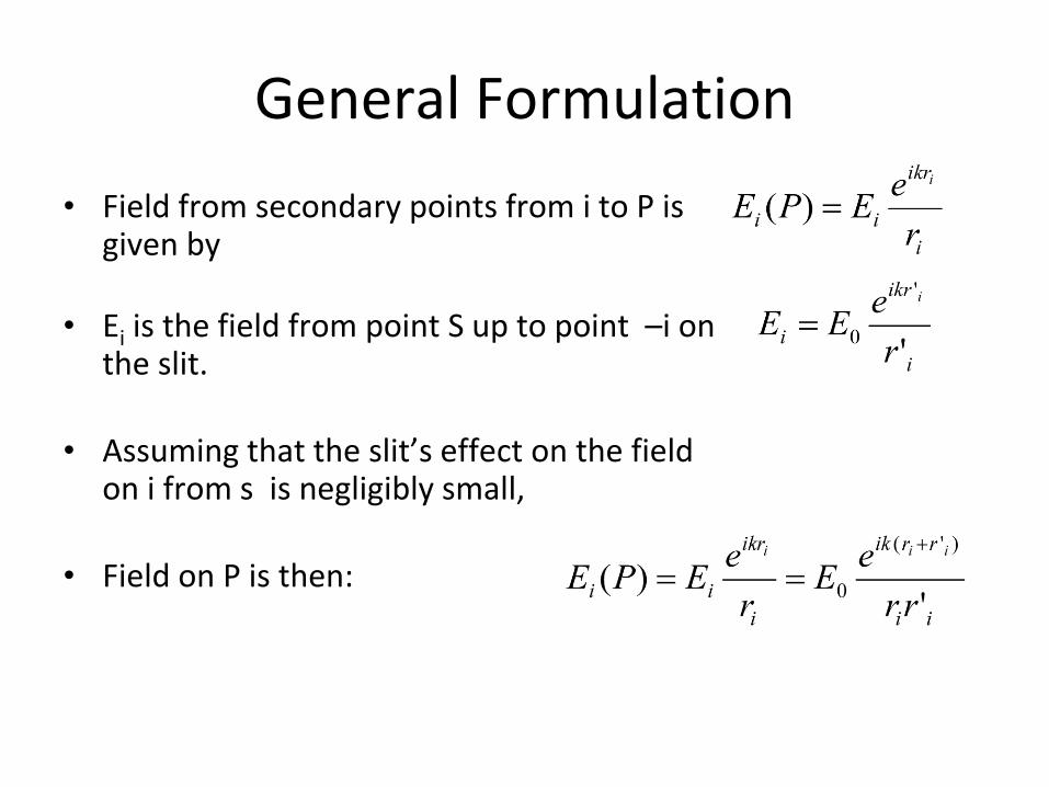
• Field from secondary points from i to P is given by
• Ei is the field from point S up to point –i on the slit.
• Assuming that the slit’s effect on the field on i from s is negligibly small,
• Field on P is then:

General Formulation
• Assuming that:The slit is further divided into small parts Δyi
within each segment the phase of the wave is uniform, if the field strength per unit length is ∈ ,each contribution of field from each segment to point P can be written as:
• Superpositioning across the slit segments:
• Imposing limit Δyi →0, then :
Type of Diffraction
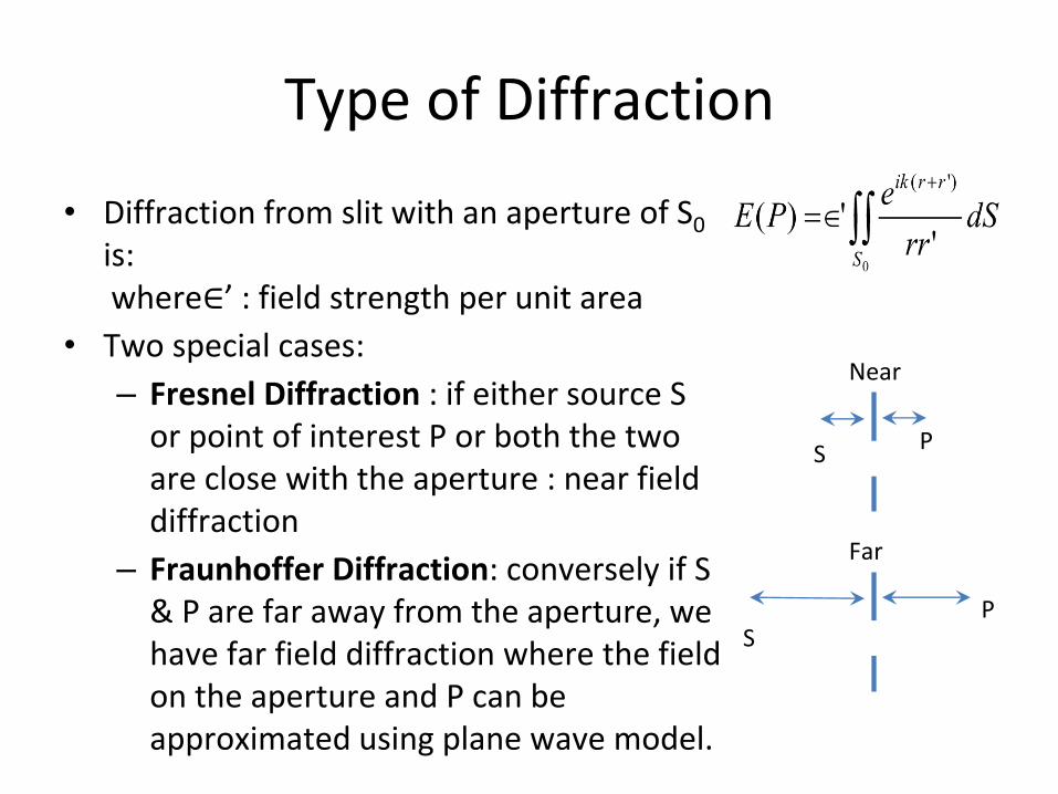
• Diffraction from slit with an aperture of S0
is:where∈’ : field strength per unit area
• Two special cases:
– Fresnel Diffraction : if either source S or point of interest P or both the two are close with the aperture : near field diffraction
– Fraunhoffer Diffraction: conversely if S & P are far away from the aperture, we have far field diffraction where the field on the aperture and P can be approximated using plane wave model.
S P
Near
SP
Far

Fraunhofer Diffraction
Fraunhoffer approximation: r,r’ >>D.
Note: to achieve this in an experiment:
- Insert collimator on the aperture on the source side- Inserting a focusing lens behind the aperture on the screen side.
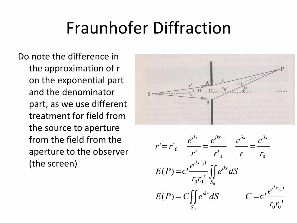
Fraunhofer Diffraction
Do note the difference in the approximation of r on the exponential part and the denominator part, as we use different treatment for field from the source to aperture from the field from the aperture to the observer (the screen)

Square Slit diffraction
The aperture function (or transmission) T(S) is defined as follow:
T(S) = 1 if S is within S0
T(S) =0 if S is outside S0
Using T(S), now, boundary of the integral S is that all points in the surface where the aperture is, not just the aperture itself.
With a square aperture:
Where r= r(x1,x2).

Diffraction from a narrow slit
An aperture with rectangular slit shape but with one dimension is significantly larger than the other (refer to the illustration).
As x1<<x2 only diffraction along x1 is considered.

Diffraction from a narrow slit
The limit of x1 and x2 are independent of each other in a rectangular slit, such that the aperture function can be expressed as the above expression.
From the picture : r = r0 + x1 sin (θ)
𝑇1 𝑥1 = 1 𝑥1 ≤ 𝐷/2
0 𝑥1 > 𝐷/2
𝑇2 𝑥2 = 1 0 ≤ 𝑥2 ≤ 𝐿/20 𝑥2 > 𝐿 𝑜𝑟 𝑥2 < 0

Diffraction from a narrow slit
On the last expression k’=k sin(θ).
and it shows E(P) to be the Fourier transform of the aperture function T1(x)
With ϕ=k’D/2= (kD/2)sin(θ)

Slit diffraction pattern
• The intensity is then : I(θ)= I0 sinc2(ϕ) , where I0= (CLD)2 • I(θ)= I0 sinc2(ϕ)
Imin=0 when ϕ = ±mπ, m=1,2,3,….
Imax when mϕ = tan(mϕ), m=0,1,2,3,….The last result is because dI/dϕ=0.

Slit diffraction pattern
• The width of the zeroth order diffraction is obtained from the first minimum at ϕ= ±π.
• FWHM (ε) is at I(ϕ)= ½ I0 → sin2(ϕ)= ½ ϕ2
• This is a nonlinear equation → difficult to solve.• Instead use approximation ε= ϕ1/2 - ϕ-1/2 = 2ϕ1/2 ≈ π• Or: (kD/2) sin θD ≈ π or
sin θD = λ/D or θ is small θD = λ/D
(width of angular diffraction)
Note that D is inversely proportional to θ, but as intensity I ∝ D2 , increasing θ means significant drop in I