documentem
TRANSCRIPT

ENGINE AND LOWER ENGINEIdentification 10
10-1
110ENGINE AND LOWER ENGINEIdentification
Vehicle type Engine Gearbox Capacity(cm3) Bore (mm) Stroke (mm) Compression
ratio
XLOBXLOC F9Q 760 PK5
PK6 1870 80 93 19:1

ENGINE AND LOWER ENGINEOil consumption 10
10-2
Oil consumption
OIL CONSUMPTION MEASUREMENT PROCEDURE
a) Topping up to the maximum level
The operation must be carried out with the engine warm (the cooling fan having cut in) and after leaving to stabilise for 15 minutes to allow all the oil to drain into the sump.
Check visually using the dipstick.
Top up to the maximum level.
Seal the drain plug (with a paint mark on both the filler plug and the sump drain plug) in order to be able to check later that it has not been removed.
b) Customer driving
Ask the customer to drive the vehicle for a period corresponding to about 1250 miles (2,000 km) or before the minimum level is reached.
c) Topping up to the maximum level
The operation must be carried out with the engine hot (the cooling fan having cut in) and after leaving to stabilise for 15 minutes.
Check visually using the dipstick.
Top up to the maximum level.
Note the quantity of oil and the mileage covered since the last top-up to maximum level.
d) Measurement of oil consumption
Quantity of oil added (in litres)OIL CONSUMPTION =
km (in thousands)

ENGINE AND LOWER ENGINEOil pressure 10
10-3
Oil pressure
CHECKING
The oil pressure should be checked when the engine is warm (approximately 80°C).
Contents of kit Mot. 836-05.
USE
B + F
Connect the pressure gauge in place of the oil pressure switch.
Oil pressure1000 rpm 1.2 bar3000 rpm 3.5 bar
SPECIAL TOOLING REQUIRED
Mot. 836-05 Oil pressure measuring kit
EQUIPMENT REQUIRED
22 mm long socket

ENGINE AND LOWER ENGINEEngine - Gearbox 10
10-4
Engine - Gearbox
REMOVAL
Put the vehicle on four axle stands (see Section 02 Lifting equipment to correctly position the lifting jack and axle stands) or on a lift.
During this operation (if using a lift) it is necessary to lash the vehicle to the lift with a strap to prevent the vehicle from toppling over.
Refer to Section 02 Underbody lift for the strap positioning.
Disconnect the battery.
NOTE:Because the battery is located under the left-hand seat, the carpet must be unclipped and removed, then the battery cover (A) by undoing the screws.
Remove:– battery cables,– the front wheels,– the engine undertray,– battery earth strap under the body and move all
cables away from the battery,
SPECIAL TOOLING REQUIRED
Mot. 1202-01Mot. 1202-02 Hose clip pliers
Mot. 1448 Distance pliers for cooling system hose clips
T. Av. 476 Ball joint extractor
TIGHTENING TORQUES (in daNm)
Shock absorber base bolts 18
Steering ball joint nut 3.7
Suspended gearbox mounting fixing nut 6.2
Lower ball joint nut 11
Brake calliper mounting bolt 3.5
Engine tie-bar fixing bolt: 10.5
Suspended engine mounting upper linkage mounting bolt 10.5
Driveshaft gaiter mounting bolt 3
Body mounting bolt for the suspended engine mounting movement limiter 4.4
Mounting bolt on the engine for suspended engine mounting cover 6.2
Wheel bolt 14.2
FOLLOW CAREFULLY THE INSTRUCTIONS GIVEN IN SECTION 13 SPECIAL FEATURES AND CLEANLINESS BEFORE CARRYING OUT ANY WORK

ENGINE AND LOWER ENGINEEngine - Gearbox 10
10-5
– lower gearbox soundproofing material at (1).
Drain:– the coolant circuit using filling equipment.– the cooling system through the radiator bottom hose– the gearbox and engine if necessary.
Right-hand side of the vehicle
Remove:– the brake calliper and attach it to the suspension
spring,– the wheel speed sensor,– lower ball joint nut (use an Allen key cut down to
X = 22 mm to lock the ball joint if necessary),
– both transmission flange mounting bolts on the relay holder bracket,
– track rod end, using tool T.Av. 476,– shock absorber base mounting bolts.
Remove the driveshaft and then remove the hub unit assembled with the driveshaft.
Left-hand side of the vehicle
Remove:– brake calliper and attach it to the suspension spring,– the wheel speed sensor,– lower ball joint nut (use an Allen key cut down to
X = 22 mm to lock the ball joint if necessary),
– track rod end, using tool T. Av. 476,– driveshaft gaiter mountings,– shock absorber base mounting bolts.
Remove the driveshaft and then remove the hub unit assembled with the driveshaft.
Remove:– number plate,– the direction indicators,– the radiator grille,

ENGINE AND LOWER ENGINEEngine - Gearbox 10
10-6
– lens unit mounting screws (2).
Disconnect the connectors from the lens units.
Remove the lens units, by removing the retaining clip (3).
Remove: – the bumper.
ENGINE AND LOWER ENGINEEngine - Gearbox 10
10-7
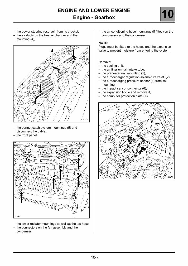
– the power steering reservoir from its bracket,– the air ducts on the heat exchanger and the
mounting (4),
– the bonnet catch system mountings (5) and disconnect the cable,
– the front panel,
– the lower radiator mountings as well as the top hose,– the connectors on the fan assembly and the
condenser,
– the air conditioning hose mountings (if fitted) on the compressor and the condenser.
NOTE:Plugs must be fitted to the hoses and the expansion valve to prevent moisture from entering the system.
Remove:– the cooling unit,– the air filter unit air intake tube,– the preheater unit mounting (1),– the turbocharger regulation solenoid valve at (2),– the turbocharging pressure sensor (3) from its
mounting,– the impact sensor connector (6),– the expansion bottle and remove it,– the computer protection plate (A).

ENGINE AND LOWER ENGINEEngine - Gearbox 10
10-8
Disconnect the connectors (5) and unclip fuse holders (6).
Remove the earth strap mountings on the gearbox and on the left-hand side member then remove the whole connection unit.
Disconnect:– the heater hoses at the bulkhead,– the brake servo vacuum pipe,– the fuel supply pipe (7) (fit anti-contamination
plugs) and connector (8),
– the mounting (9),– the clutch slave cylinder pipe by removing clip (B)
and remove it,
– the upper gearbox soundproofing material,

ENGINE AND LOWER ENGINEEngine - Gearbox 10
10-9
– the gearbox control cables,– the heater matrix casing (C) by disconnecting the
connector (1),
– the thermoplunger unit mounting (2) and remove the thermoplunger unit,
– the power assisted steering hoses on the steering box (drain the power steering reservoir first).
– the mounting bolt (3) and undo bolt (4),
– the exhaust downpipe mountings.
Disconnect the fuel tank sender connector at (5), unclip it from under the body and attach it to the engine.
Attach the workshop hoist.
Support the engine and gearbox assembly using a hoist.

ENGINE AND LOWER ENGINEEngine - Gearbox 10
10-10
Remove:– the power steering pipe mounting (7) and remove the
power steering pipe,– the lower crossmember (A) and front
crossmember (B),
– the nut (1) and tap it with a copper hammer to release the stud,
– the tie-rod (2) mounting bolts, then remove the suspended mounting movement-limiter assembly.
Using a workshop crane, remove the engine-gearbox assembly.
REFITTING
Refit the engine-gearbox assembly following the same method as for removal.
Refit:– the left suspended mounting,– the right suspended mounting,– the engine tie-bar.
See Section 19 Suspended engine mounting for the tightening torques.

ENGINE AND LOWER ENGINEEngine - Gearbox 10
10-11
Special notes on the clutch slave cylinder when separating the engine and gearbox
IMPORTANT:To prevent damage occurring to the slave cylinder, do not coat the gearbox output shaft with lubricant.
NOTE:To prevent leaks, replace the slave cylinder after replacing the clutch mechanism.
Add brake fluid to the reservoir.
Bleed the system using bleed screw (A) located on the union on the slave cylinder.
Make sure that the brake fluid reservoir is never empty.
Top up the brake fluid.
IMPORTANT: Tighten the bleed screw to a torque of 1 daNm.
Refit the engine-gearbox assembly following the same method as for removal.
Refit:– the left suspended mounting,– the right suspended mounting,– the engine tie-bar.
See Section 19 Suspended engine mounting for the tightening torques.
Refit in reverse order to that for removal.
Perform the following operations:– fill the gearbox with oil,– fill the engine with oil, if necessary,– fill and bleed the cooling circuit (see Section 19
Filling - bleeding),– fill and bleed the power assisted steering circuit,– fill the coolant circuit using the filling equipment.
Apply Loctite FRENBLOC to the brake calliper mounting bolts before fitting and tighten them to the correct torque.
Depress the brake pedal several times to bring the pistons into contact with the brake pads.
FOLLOW CAREFULLY THE INSTRUCTIONS GIVEN IN SECTION 13 SPECIAL FEATURES FOR THE PROCEDURE FOR STARTING THE ENGINE.

ENGINE AND PERIPHERALSCleanness & Safety 10A110A:ENGINE AND PERIPHERALSCleanness & Safety
OPERATION
The Common Rail high-pressure direct injection system is a sequential diesel injection system (based on the multipoint injection system for petrol engines).
This new injection system reduces operating noise, reduces the volume of pollutant gases and particles and produces high engine torque at low engine speeds thanks to a pre-injection procedure.
The low pressure pump supplies the high pressure pump via the pressure regulator filter and then the fuel filter exclusively during the starting phase.With a pressure between 2 and 4 bar.
The High Pressure pump generates the high pressure sent to the injector rail. The pressure regulator located on the pump modulates the high pressure pump supply flow. The rail supplies each injector through a steel pipe.
The computer:– determines the value of injection pressure necessary for the engine to operate correctly and then controls the
pressure regulator. It checks that the pressure value is correct by analysing the value transmitted by the pressure sensor located on the rail,
– determines the injection time necessary to deliver the right quantity of diesel and the moment when injection should start,
– controls each injector electrically and individually after determining these two values.
The injected flow to the engine is determined by:– the duration of injector control,– the injector opening and closing speed,– the needle stroke (determined by the type of injector),– the normal hydraulic flow of the injector (determined by the type of injector),– the high-pressure rail pressure controlled by the computer.
THE CLEANLINESS AND SAFETY ADVICE SPECIFIED IN THIS DOCUMENT MUST BE FOLLOWED DURING ANY WORK CARRIED OUT ON THE HIGH-PRESSURE INJECTION SYSTEM.
10A-1

ENGINE AND PERIPHERALSCleanness & Safety 10A
10A-2
CLEANLINESS INSTRUCTIONS WHICH MUST BE FOLLOWED WHEN WORKING ON THE HIGH-PRESSURE DIRECT INJECTION SYSTEM
Risks relating to contamination
The system is very sensitive to contamination. The risks caused by the introduction of contamination are:– damage to or destruction of the high-pressure injection system,– a component seizing or leaking.
All After-Sales operations must be performed under very clean conditions. This means that no impurities (particles a few microns in size) should get into the system during dismantling or into the circuits via the fuel unions.
The cleanliness principle must be applied from the filter through to the injectors.
WHAT ARE THE SOURCES OF CONTAMINATION?Contamination is caused by:– metal or plastic chips,– paint,– fibres:
● of cardboard,● brushes,● paper,● clothing,● cloths,
– foreign bodies such as hairs,– ambient air,– etc.
IMPORTANT:it is forbidden to clean the engine using a high pressure washer because of the risk of damaging connections. Furthermore, moisture may collect in the connectors and cause electrical connection problems.

ENGINE AND PERIPHERALSCleanness & Safety 10A
10A-3
INSTRUCTIONS TO BE FOLLOWED BEFORE ANY WORK IS CARRIED OUT ON THE INJECTION SYSTEM
● Ensure that you have the plugs for the unions to be opened (bag of plugs sold by the Parts Stores - Part No. 77 01 206 381).Plugs are to be used once only. After use, they must be thrown away (once used they are soiled and cleaning is not sufficient to make them reusable). Unused plugs must be thrown away.
● Ensure that you have the resealable plastic bags for storing removed parts. Stored parts will therefore be less subject to the risk of impurities. The bags must be used only once, and after use they must be thrown away.
● Ensure that you have lint-free cleaning towels (towels referenced 77 11 211 707). The use of a normal cloth or paper for cleaning purposes is forbidden. These are not lint free and may contaminate the fuel circuit of the system. Each lint-free cloth should only be used once.
INSTRUCTIONS TO BE FOLLOWED BEFORE OPENING THE FUEL CIRCUIT
● Use new thinner for each operation, (used thinner contains impurities). Pour it into a clean receptacle.
● For each operation, use a clean brush which is in good condition (the brush must not lose its hairs).
● Use a brush and thinner to clean the connections to be opened.
● Blow compressed air over the cleaned parts (tools, cleaned the same way as the parts, connections and injection system zone). Check that no bristles have been left behind.
● Wash your hands before and during the operation if necessary.
● When wearing leather protective gloves, cover them with latex gloves.
INSTRUCTIONS TO BE FOLLOWED DURING THE OPERATION
● As soon as the circuit is open, all openings must be plugged to prevent impurities from entering the system. The plugs to be used are available from the Parts Stores (part number 77 01 206 381). They must not, under any circumstances, be reused.
● Close the resealable bag, even if it has to be reopened shortly afterwards. Ambient air carries impurities.
● All components removed from the injection system must be stored in a hermetically sealed plastic bag once the plugs have been inserted.
● The use of a brush, thinner, bellows, sponge or normal cloth is strictly forbidden once the circuit has been opened. These items are likely to allow impurities to enter the system.
● A new component replacing an old one must not be removed from its packaging until it is to be fitted to the vehicle.

ENGINE AND PERIPHERALSCleanness & Safety 10A
10A-4
INSTRUCTIONS FOR FITTING THE PLUGS (part number 77 01 206 381)

ENGINE AND PERIPHERALSCleanness & Safety 10A
10A-5
POST-REPAIR CHECK
Re-prime the circuit. To do this, turn the low-pressure pump over by switching on the ignition several times, or turn the low-pressure pump over with the diagnostic tool using the "Actuator Commands" menu.
IMPORTANT: the engine must not run with diesel containing more than 10% diester.
The system injects the diesel fuel into the engine at a pressure of up to 1350 bar. Before any intervention, check that the injector rail is depressurised.
It is absolutely vital that you observe the tightening torque:– of the high-pressure pipes,– of the cylinder head injector,– of the pressure sensor.
When the high-pressure pump, injectors and high pressure supply, output and return unions are removed or repaired, all openings should be fitted with new blanking plugs of the correct size to prevent contamination entering.
WARNING: ALL PIPES REMOVED MUST BE REPLACED.
When replacing the high pressure pipe, follow the method below:– remove the high pressure pipe, holding the filter rod on the injector with a lock-wrench,– fit anti-contamination plugs,– loosen the high pressure rail,– fit the new high pressure pipe,– offer up the unions by hand until they touch,– tighten the high pressure rail mountings to torque,– torque-tighten the union at the injector side,– tighten the high pressure rail connection to torque.
Dismantling the interior components of the pump is prohibited.
The fuel return pipe fitted to the injectors must be replaced when it is removed.
The diesel temperature sensor cannot be removed. It is part of the fuel return rail.
Loosening a high pressure pipe connection when the engine is running is prohibited.
After any operation, check that there are no diesel leaks. Run the engine at idle speed until the engine cooling fan starts up, then accelerate several times with no load.

ENGINE AND PERIPHERALSForeword 10A
10A-6
Foreword
USING THE MANUAL
There are two main sections in this manual:– technical specifications,– overhauling the engine.
UNITS OF MEASUREMENT
– All dimensions are given in millimetres (mm) (unless stated otherwise).
– Tightening torques are expressed in decaNewton.metres (daN.m).Reminder: 1 daNm = 1.02 m.kg.
– Pressures in barReminder: 1 bar = 100,000 Pa.
TOLERANCES
Tightening torques given without a tolerance must be accurate to within:– in degrees (± 3°),– in daN.m (± 10%).

ENGINE AND PERIPHERALSEngine identification 10A
10A-7
Engine identification
The engine identification is stamped on the cylinder block.
It includes:A: the engine type B: the engine approval letter D: the identification of RENAULTE: the engine suffixF: the engine fabrication number G: the engine assembly plant
Engine Suffix CompressionRatio Bore (mm) Stroke (mm) Cubic capacity
(cc)
F9Q
718, 732, 733, 738,740, 746, 748, 750,751, 752, 754, 756,760, 762, 772, 790
19:1 80 93 1870
ENGINE AND PERIPHERALSTightening torques (in daN.m or in degrees) 10ATightening torques (in daN.m or in degrees)
10A-8
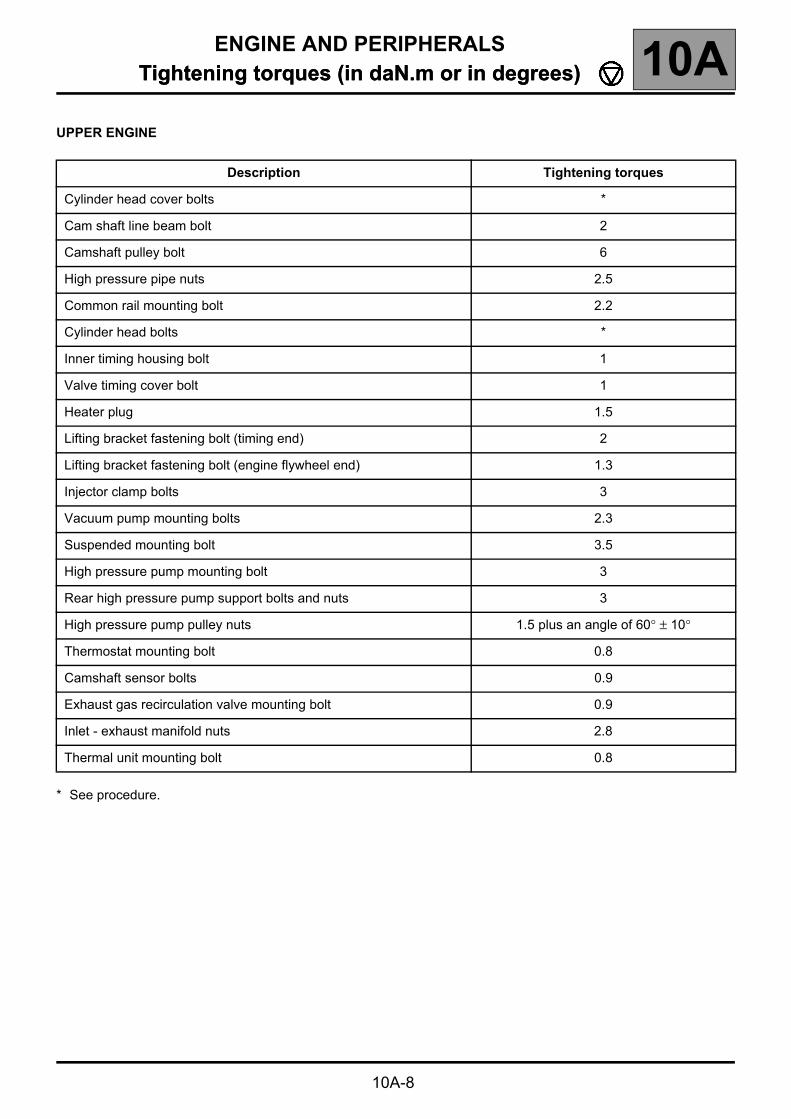
UPPER ENGINE
* See procedure.
Description Tightening torques
Cylinder head cover bolts *
Cam shaft line beam bolt 2
Camshaft pulley bolt 6
High pressure pipe nuts 2.5
Common rail mounting bolt 2.2
Cylinder head bolts *
Inner timing housing bolt 1
Valve timing cover bolt 1
Heater plug 1.5
Lifting bracket fastening bolt (timing end) 2
Lifting bracket fastening bolt (engine flywheel end) 1.3
Injector clamp bolts 3
Vacuum pump mounting bolts 2.3
Suspended mounting bolt 3.5
High pressure pump mounting bolt 3
Rear high pressure pump support bolts and nuts 3
High pressure pump pulley nuts 1.5 plus an angle of 60° ± 10°
Thermostat mounting bolt 0.8
Camshaft sensor bolts 0.9
Exhaust gas recirculation valve mounting bolt 0.9
Inlet - exhaust manifold nuts 2.8
Thermal unit mounting bolt 0.8
ENGINE AND PERIPHERALSTightening torques (in daN.m or in degrees) 10A
10A-9
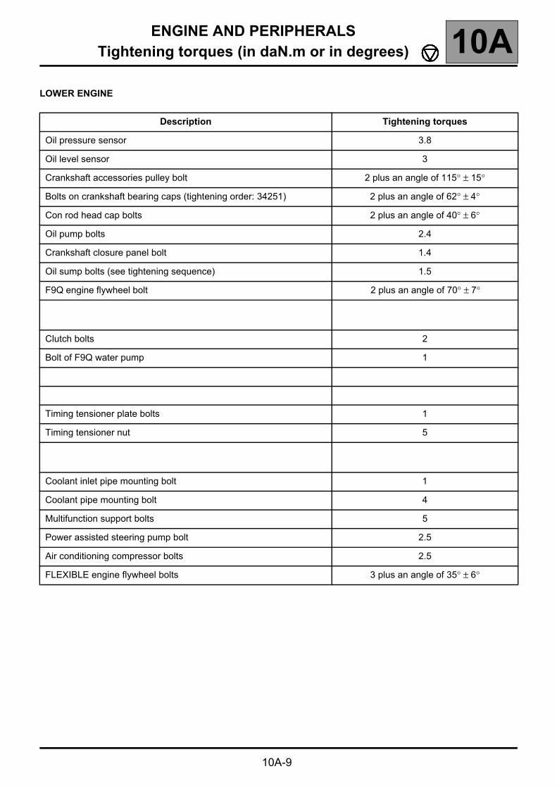
LOWER ENGINE
Description Tightening torques
Oil pressure sensor 3.8
Oil level sensor 3
Crankshaft accessories pulley bolt 2 plus an angle of 115° ± 15°
Bolts on crankshaft bearing caps (tightening order: 34251) 2 plus an angle of 62° ± 4°
Con rod head cap bolts 2 plus an angle of 40° ± 6°
Oil pump bolts 2.4
Crankshaft closure panel bolt 1.4
Oil sump bolts (see tightening sequence) 1.5
F9Q engine flywheel bolt 2 plus an angle of 70° ± 7°
Clutch bolts 2
Bolt of F9Q water pump 1
Timing tensioner plate bolts 1
Timing tensioner nut 5
Coolant inlet pipe mounting bolt 1
Coolant pipe mounting bolt 4
Multifunction support bolts 5
Power assisted steering pump bolt 2.5
Air conditioning compressor bolts 2.5
FLEXIBLE engine flywheel bolts 3 plus an angle of 35° ± 6°

ENGINE AND PERIPHERALSTightening torques (in daN.m or in degrees) 10A
10A-10
Description Tightening torques
Alternator bolts 2.5
Accessories tensioner roller bolts on cylinder block 2.5
Oil decanter bolts 1
Top dead centre plug 2
Turbocharger mounting nuts 2.4
Turbo oil inlet union (cylinder block end) 2.3
Turbo oil inlet union (pipe end) 2.4
Turbo oil inlet union (turbocharger end) 2.6
Mounting bolts on turbocharger oil return pipe (turbocharger end) 1.2
Light-off catalyst mounting nuts to turbo 2.5
Exhaust stay bolt:– M8– M10
2.44.3
Anti-emulsion plate mounting bolts 2.4
Auto tensioner mounting bolts 4.3

ENGINE AND PERIPHERALSSpecifications 10A
10A-11
Specifications
CYLINDER HEAD
Cylinder head tightening procedure
REMINDER: to obtain correct tightening of the bolts, remove any oil from the cylinder head securing holes using a syringe.
All cylinder head bolts must always be changed after removal. There is no cylinder head retightening operation.
Tighten all the bolts to 3 daN.m, then angle tighten to 100° ± 4°, in the sequence shown below.
Wait 3 minutes settling time.
Cylinder head tightening is carried out in stages, and the following procedure is applied successively to bolts 1-2 then 3-4, 5-6, 7-8 and 9-10
Loosen bolts 1-2 until they are completely free.
Tighten bolts 1-2 to 2.5 daNm, then angle tighten to 213° ± 7°.
Repeat the loosening and tightening operations for bolts 3-4, 5-6, 7-8 and 9-10.
There is no cylinder head retightening operation.

ENGINE AND PERIPHERALSSpecifications 10A
10A-12
Thickness of the cylinder head gasket
The thickness of the cylinder head gasket is measured at (A):– thickness of the gasket when tightened:
1.32 ± 0.05 mm.
Checking piston protrusion
Clean the piston heads in order to eliminate any traces of deposits.
Turn the crankshaft one turn in its operating direction to bring piston No. 1 close to top dead centre.
Fit tool Mot. 251-01 equipped with a gauge on support plate Mot. 252-01, and find top dead centre.
NOTE:All measurements are to be carried out in the longitudinal axis of the engine, in order to eliminate any errors due to piston tilting.
WARNING:the gauge detector must not be in the valve clearance.
Measure the piston protrusion.
The protrusion must be: 0.56 ± 0.06 mm.

ENGINE AND PERIPHERALSSpecifications 10A
10A-13
Height of the cylinder head (in mm)
H = 162.75 ± 1.75
Gasket face deformation (in mm): 0.05
NO REGRINDING IS AUTHORISED
Valves
Stem diameter (in mm)
Inlet: 6.985 ± 0.011Exhaust: 6.971 ± 0.011
Face angle
Inlet and exhaust:: 90º
Head diameter (in mm)
Inlet: 35.325 ± 0.125Exhaust: 32.625 ± 0.125
Valve length (in mm)
Inlet: 110.99 ± 0.20Exhaust: 110.79 ± 0.20
Max. valve lift (in mm)
Inlet: 8.866Exhaust: 10.344
Protrusion of valves in relation to the cylinder head gasket face (in mm)
Inlet and exhaust: 0.09 ± 0.12
Valve clearance settings (in mm)
Inlet: 0.20 ± 0.05Exhaust: 0.40 ± 0.05
ENGINE AND PERIPHERALSSpecifications 10A
10A-14
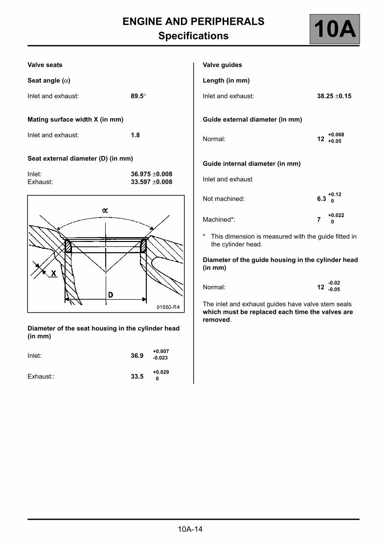
Valve seats
Seat angle (α)
Inlet and exhaust: 89.5°
Mating surface width X (in mm)
Inlet and exhaust: 1.8
Seat external diameter (D) (in mm)
Inlet: 36.975 ±0.008Exhaust: 33.597 ±0.008
Diameter of the seat housing in the cylinder head (in mm)
+0.007 Inlet: 36.9 -0.023
+0.029Exhaust:: 33.5 0
Valve guides
Length (in mm)
Inlet and exhaust: 38.25 ±0.15
Guide external diameter (in mm)
+0.068 Normal: 12 +0.05
Guide internal diameter (in mm)
Inlet and exhaust
+0.12 Not machined: 6.3 0
+0.022 Machined*: 7 0
* This dimension is measured with the guide fitted in the cylinder head.
Diameter of the guide housing in the cylinder head (in mm)
-0.02 Normal: 12 -0.05
The inlet and exhaust guides have valve stem seals which must be replaced each time the valves are removed.

ENGINE AND PERIPHERALSSpecifications 10A
10A-15
It is essential to fit the valve stem seals using tool Mot. 1511 or other suitable equipment.
NOTE:Do not lubricate the valve stem seals before fitting them.
Tool Mot. 1511 consists of:– four cores (1),– four pushrods (2),– one guide tube (3),– one sleeve (4).
Angle of the inlet and exhaust guides (in degrees)
Inlet and exhaust: α = 90
Position of the inlet and exhaust valve guides (in mm)
Inlet and exhaust: A = 81.05 ± 0.4
ENGINE AND PERIPHERALSSpecifications 10A
10A-16
Valve springs
Free length (in mm): 46 ± 2
Length under load (in mm):
27 daN 37.561.4 daN 27.5
Close-wound coils (in mm): 25.07 ± 0.1
Diameter of wire (in mm): 3.90 ± 0.03
Internal diameter (in mm): 21.5 ± 0.1
External diameter (in mm): 29.5
Pistons
External diameter of tappet (in mm): 34.975 ± 0.01
Diameter of the housing in the cylinder head (in mm):
+0.039 35 0
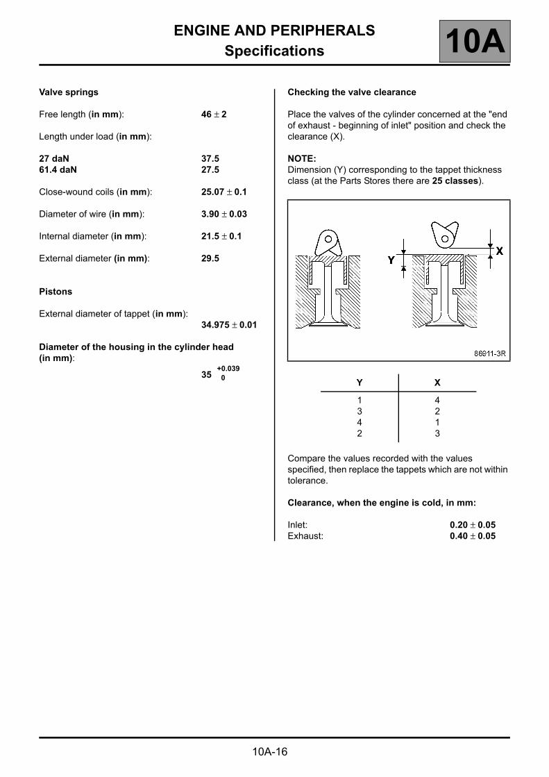
Checking the valve clearance
Place the valves of the cylinder concerned at the "end of exhaust - beginning of inlet" position and check the clearance (X).
NOTE:Dimension (Y) corresponding to the tappet thickness class (at the Parts Stores there are 25 classes).
Compare the values recorded with the values specified, then replace the tappets which are not within tolerance.
Clearance, when the engine is cold, in mm:
Inlet: 0.20 ± 0.05Exhaust: 0.40 ± 0.05
Y X
1342
4213

ENGINE AND PERIPHERALSSpecifications 10A
10A-17
The camshaft must be removed to replace the tappets.
Determining dimension (Y).
Set up the following assembly using Mot. 252-01 and Mot. 856-02, then calibrate the gauge.
Raise the gauge extension (without modifying the position of the magnetic support/gauge assembly), then slide in the tappet to be measured.
Note dimension (Y) and repeat the operation for the tappets where the valve clearance is not within tolerance.
Refer to the "Replacement parts catalogue" for the vehicle concerned to select the various thicknesses of the tappet(s).
Camshaft
End play (in mm) 0.045 to 0.135
Number of bearings 5
Timing diagram
* If the inlet opening delay is negative, valve opening can be found after top dead centre.
** If the exhaust closing advance is negative, valve closing can be found before top dead centre.
– Inlet opening retardation *– Inlet closing retard – Exhaust opening advance – Exhaust closing advance **
- 32146- 5

ENGINE AND PERIPHERALSSpecifications 10A
10A-18
1 Cylinder block top dead centre fixed mark2 Flywheel top dead centre moving mark3 Flywheel bottom dead centre moving mark4 Inlet opening retardation 5 Exhaust closing advance 6 Inlet closing retardation 7 Exhaust opening advance 8 Direction of engine rotation (flywheel end)
PISTONS
Fitting the gudgeon pin in the con rod and in the piston.
The gudgeon pin is retained by circlips.
These engines are fitted with KOLBENSCHMIDT pistons.
Piston marking
1 Direction of fitting of the piston: Λ towards the flywheel
2 Height between the gudgeon pin and the top of the piston (see table on following page)
3 Used by the supplier only4 Used by the supplier only5 Piston axis of symmetry6 Gudgeon pin hole axis7 Offset between the hole of the pin (6) and the axis
of symmetry of the piston (5): 0.5 mm

ENGINE AND PERIPHERALSSpecifications 10A
10A-19
Table of gudgeon pin heights
The tolerance on the pin heights is ± 0.02 mm.
* The different gudgeon pin heights are exclusively reserved for the engine assembly plant.
The Parts Stores will only supply piston classes (height) L, M, N.
NOTE:– if the engine is fitted with a K class piston, an L class
piston must be fitted as a replacement,– if the engine is fitted with a P class piston, an N class
piston must be fitted as a replacement,
Measuring the piston diameter
The piston diameter is measured at height A = 39 mm.
Piston diameter (in mm): 79.866 ± 0.0075
Rings
Three rings (thickness in mm)
-0.01– Compression ring 2.5 -0.03
-0.01– Sealing 2 -0.03
-0.01– Scraper 3 -0.03
The rings are supplied ready adjusted.
T = Top
Clearance at the gap
Mark on piston* Pin height (mm)
K 47.046
L 47.088
M 47.130
N 47.172
P 47.214
Rings Clearance at the gap (in mm)
Compression 0.2 to 0.35
Sealing 0.7 to 0.9
Scraper 0.25 to 0.5

ENGINE AND PERIPHERALSSpecifications 10A
10A-20
Gudgeon pin (in mm)
All types except F9Q 750 and 756
Length: 59.7 to 60
External diameter: 27.995 to 28
Internal diameter: 13.8 to 14.1
F9Q 750 and 756
Length: 59.5 to 60
External diameter: 27.995 to 28
Internal diameter: 12.8 to 13.1
CON RODS
The con rods are DIVISIBLE.
Lateral play of the con rod big end (in mm):0.22 to 0.482
Diametral play of the con rod big end (in mm):0.027 to 0.086
Centre-to-centre distance between the con rod big end and small end (in mm):
139
Diameter of the big end (in mm): +0.019 51.587 0
Diameter of the small end (in mm):+0.025
(without ring) 30.24 0+0.025
(with ring) 28 +0.013
NOTE: the con rod small end bushings cannot be replaced.
WARNING:– The bolts must be sealed with engine oil under the
heads and on the threads when the con rods are fitted in the engine.
– Positioning of the con rod heads on the body is ensured by roughnesses on the crack.
– The occurrence of impacts or a foreign body between the body-head mating surfaces will lead to rapid failure of the con rod.

ENGINE AND PERIPHERALSSpecifications 10A
10A-21
IMPORTANT:Do not use a sharp point to mark the bearing caps in relation to their con rods to avoid starting a crack in the rod.
Use a permanent marker pen.
The maximum weight difference for the con rod, piston and gudgeon pin assemblies for the same engine must be 23 grams.

ENGINE AND PERIPHERALSSpecifications 10A
10A-22
Direction of fitting of the con rod in relation to the piston
Place the "∧" (1) engraved on the piston head downwards and the machined flat (2) of the con rod head upwards.
Direction for fitting the circlips on the piston
Fit the circlips on the piston as shown below.
CRANKSHAFT
Number of main journals 5
Lateral crankshaft play (in mm):0.067 to 0.233
Diametral crankshaft play (in mm):0.027 to 0.086
Diameter of the main bearing journals
Main bearing journal diameters are shown on the crankshaft by paint marks.
Diameter of the crankpins (in mm):48.01 ± 0.01
The lateral shims are located on bearing No. 2.
NO REGRINDING IS AUTHORISED
Paint mark Blue Red
Journal diameter(in mm)
54.785 inclusive to
54.795 exclusive
54.795 inclusive to
54.805 exclusive

ENGINE AND PERIPHERALSSpecifications 10A
10A-23
BEARING SHELLS
Crankshaft bearing shells
The engine is fitted with bearing shells without a locator notch.
The crankshaft bearing shells are fitted on the cylinder block and on the bearings using tool Mot. 1493.

ENGINE AND PERIPHERALSSpecifications 10A
10A-24
Direction of fitting:– the cylinder block bearings are
fitted with grooved bearing shells,
– the bearing caps are fitted with non-grooved bearing shells.

ENGINE AND PERIPHERALSSpecifications 10A
10A-25
Con rod bearing shells
The engine is fitted with bearing shells without a locator notch.
The bearing shells are fitted using Mot. 1492 and Mot. 1492-01.

ENGINE AND PERIPHERALSSpecifications 10A
10A-26
PREPARING THE ENGINE TO BE SET ON THE STAND
Before the engine is mounted on the stand Mot. 792-03, the engine's electrical harness must be removed and the engine oil drained.
Remove:– the stay between the cylinder block and the light-off
catalyst,– the turbocharger oil return pipe,
– the turbocharger oil supply pipe,– the three turbocharger mounting nuts on the exhaust
manifold.

ENGINE AND PERIPHERALSSpecifications 10A
10A-27
Change to the cylinder block
To optimise the acoustics, a change has been made to the cylinder block mating face.
Conventional cylinder block with a small mating face
New cylinder block with a large mating face

ENGINE AND PERIPHERALSSpecifications 10A
10A-28
New cylinder block with a large mating face
Fit rods (B), (N1), (P) Mot. 1575 onto the cylinder block such that they fit into holes (26, 12, 25) in the plate (Mot. 792-03).
Change to DESVIL engine mountings head used in engine repair. Replacement of head TS 126 (1) with head TS 127 (2).
Special feature of this new head:– axis of rotation permanently lubricated,– variable locking of the head.
IMPORTANT:The clamping bolt (3) must be fully undone to release the head when there is no longer an engine resting on the support.
Conventional cylinder block with a small mating face
Fit rods (B), (N), (P) Mot. 995 onto the cylinder block such that they fit into holes (26, 12, 25) in the plate (Mot. 792-03).
ENGINE AND PERIPHERALSSpecifications 10A
10A-29
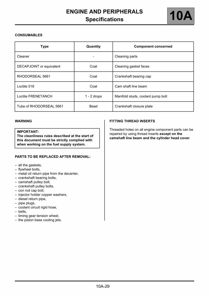
CONSUMABLES
WARNING
PARTS TO BE REPLACED AFTER REMOVAL:
– all the gaskets,– flywheel bolts,– metal oil return pipe from the decanter,– crankshaft bearing bolts,– camshaft pulley bolt,– crankshaft pulley bolts,– con rod cap bolt,– injector holder copper washers,– diesel return pipe,– pipe plugs,– coolant circuit rigid hose,– belts,– timing gear tension wheel,– the piston base cooling jets.
FITTING THREAD INSERTS
Threaded holes on all engine component parts can be repaired by using thread inserts except on the camshaft line beam and the cylinder head cover.
Type Quantity Component concerned
Cleaner - Cleaning parts
DECAPJOINT or equivalent Coat Cleaning gasket faces
RHODORSEAL 5661 Coat Crankshaft bearing cap
Loctite 518 Coat Cam shaft line beam
Loctite FRENETANCH 1 - 2 drops Manifold studs, coolant pump bolt
Tube of RHODORSEAL 5661 Bead Crankshaft closure plate
IMPORTANT:The cleanliness rules described at the start of this document must be strictly complied with when working on the fuel supply system.

ENGINE AND PERIPHERALSStandard replacement 10A
10A-30
Standard replacement
PREPARING THE USED ENGINE FOR RETURN
The engine should be cleaned and drained (oil and water).
Leave on the used engine or include in the return box:– the oil filter,– the oil pressure switch,– the water pump,– the high pressure pump,– the rail,– the injectors– the heater plugs,– the oil trap,– the dipstick,– the vacuum pump,– the flywheel,– the clutch
Remember to remove:– all coolant pipes,– the inlet and exhaust manifolds,– the alternator,– the power-assisted steering pump,– the air conditioning compressor,– the multifunction support,– the oil level sensor,– the cylinder head coolant outlet unit.
The used engine should be secured to the base under the same conditions as the overhauled engine:– plastic plugs and covers fitted,– cardboard cover over the assembly.

ENGINE AND PERIPHERALSEssential special tooling 10AEssential special tooling
Illustration Part No.Method
Part Storereference Description
Emb. 880 00 00 088 000 Pin extractor.
Mot. 11 00 01 072 500 Crankshaft bearing extractor.
Mot. 251-01 00 00 025 101 Gauge stand; used with Mot. 252-01.
Mot. 252-01 00 00 025 201 Thrust plate for measuring the protrusion of cylinder liners, used with Mot. 251-01.
Mot. 445 00 00 044 500 Oil filter wrench.
Mot. 582-01 00 00 058 201 Flywheel immobilisation segment.
Mot. 591-02 00 00 059 102 Magnetised flexible shaft for angular wrench for tightening cylinder head.
Mot. 591-04 00 00 059 104 Angular wrench for tightening cylinder head, 1/2" drive with index.
10A-31

ENGINE AND PERIPHERALSEssential special tooling 10A
10A-32
Illustration Part No.Method
Parts Storereference Description
Mot. 799-01 00 00 079 901 Tool for immobilising pinions for the toothed timing belt
Mot. 988-02 00 00 098 802 Tool for fitting the camshaft seal at the timing end.
Mot. 990-03 00 00 099 003 Tool for fitting crankshaft seal, timing end.
Mot. 991-01 00 00 099 101 Tool for fitting crankshaft seal, flywheel end.
Mot. 1054 00 00 105 400 TDC setting rod.
Mot. 1200-01 00 00 120 001 High pressure pump pin immobiliser.
Mot. 1200-02 00 00 120 002 Injection pump pulley immobiliser.

ENGINE AND PERIPHERALSEssential special tooling 10A
10A-33
Illustration Part No.Method
Parts Storenumber Description
Mot. 1281-01 00 00 128 101 Oil filter cap.
Mot. 1335 00 00 113 500 Tool for removing valve stem seals.
Mot. 1387 00 00 138 700 Tool for checking the accessories belt tension.
Mot. 1423 00 00 142 300 Tool for removing the silicon crankshaft bearing cap.
Mot. 1485Mot. 1485-01
00 00 148 50000 00 148 501 Tool for removing piston coolers.
Mot. 1492 00 00 149 200 Tool for fitting con rod bearing shells.
Mot. 1492-01 00 00 149 201 Adaptation kit for fitting the separable con rod bearing shells.
Mot. 1566 00 00 156 600 Tool for removing high pressure pipes

ENGINE AND PERIPHERALSEssential special tooling 10A
10A-34
Illustration Part No.Method
Parts Storenumber Description
Mot. 1493 00 00 149 300 Tool for fitting crankshaft bearing shells.
Mot. 1505 00 00 150 500 Device for checking the belt tension.
Mot. 1511 00 00 151 100 Tool for fitting valve stem seals.
Mot. 1516 00 00 151 600 Tool for refitting piston coolers orientated at 5°.
Mot. 1516-01 00 00 151 601 Plate for refitting piston coolers orientated at 3° (addition to Mot. 1516).
Mot. 1525 00 00 152 500 Tapered hub pump pin extractor.
Mot. 1525-01 00 00 152 501 Fitting clips for Mot. 1525 for F9Q Common Rail engines.
Mot. 1543 00 00 154 300 Timing belt pretensioning tool.
Mot. 1516-02 00 00 151 602 Plate for refitting piston coolers (orientated at 0°) (addition to Mot. 1516).

ENGINE AND PERIPHERALSEssential special tooling 10A
10A-35
Illustration Part No.Method
Parts Storenumber Description
Mot. 1551 00 00 155 100 Tool for fitting the oil return pipe.
Mot. 1573 00 00 157 300 Cylinder head support.
Rou. 15-01 00 01 331 601 Internal shaft protector ∅ 16 mm.
Mot. 1575 00 00 157 500 Engine mounting pin "N1" (addition to Mot. 792-03 for Desvil engine stand).
Mot. 445-01 00 00 044 501 Replacement strap for Mot. 445.
Mot. 792-03 00 00 079 203 Engine support plate for Desvil engine stand (with pins from A to W).
Mot. 995 00 00 099 500 Set of two pins adaptable to engine mounting plate Mot. 792-03.

ENGINE AND PERIPHERALSEssential special tooling 10A
10A-36
Illustration Part No.Method
Parts Storenumber Description
Mot. 1569 00 00 156 900 Cone for fitting the pistons in the cylinder block.
Mot. 1577 00 00 157 700 Lip seal extractor ∅ 28 mm to ∅ 50 mm.
Mot. 1578 00 00 157 800 Lip seal extractor ∅ 50 mm to ∅ 75 mm.
Mot. 1579 00 00 157 900 Lip seal extractor ∅ 80 mm to ∅ 95 mm.
Mot. 1635 00 00 163 500 Tool for fitting elastomer crankshaft seal, flywheel end.
Mot. 1636 00 00 163 600 Tool for fitting elastomer crankshaft seal, timing end.
Mot. 1592 00 00 159 200 Flexible end piece for taking pressure at end of compression.
Mot. 1676 00 00 167 600 Accessories belt tensioner.
Mot. 1677 00 00 167 700 Flywheel immobilisation segment for cylinder block large face.

ENGINE AND PERIPHERALSEssential equipment 10A
10A-37
Essential equipment
Description
Standard 22 mm long socket 1/2" (12.7 mm squared) for removing the oil pressure gauge.
Standard 1/2" 8 / 12 / 14 female torx socket (12.7 mm squared).
Angular tightening tool from:● STAHLWILLE part number 540 100 03 for example,● FACOM part number DM2360 for example,● SAM part number 1 SA, for example.
FACOM tool for fitting the valve stem seals, part number DM6J4, for example.
Gun for using tube of RHODORSEAL 5661.
Wrench for removing high pressure pipes, e.g. FACOM part number DM 19
Articulated wrench for removing and refitting the heater plugs, e.g. FACOM part number B10R10A.
Clamp for internal circlips.
Valve spring compressor.

ENGINE AND PERIPHERALSEssential equipment 10A
10A-38
Description
"Crowfoot" end-piece for torque-tightening high pressure pipes, e.g. FACOM part number 18.17.
Crankshaft bearing puller, e.g. FACOM part number U49 A D5.
"Crowfoot" end-piece for torque-tightening high pressure pipes, e.g. FACOM part number 19.17.

ENGINE AND PERIPHERALSOverhauling the engine 10A
10A-39
Overhauling the engine
Remove the accessories drive belt by turning the spanner to the right to loosen the belt.
Remove the Top Dead Centre pin plug.
REMOVING THE UPPER ENGINE
Engine fitted with a water pump driven by the timing belt.
Remove:– the exhaust gas recirculation
pipe,– the ring for lifting the engine at the
timing end,– the intake and exhaust manifolds.

ENGINE AND PERIPHERALSOverhauling the engine 10A
10A-40
Timing adjustment
Rotate the crankshaft in clockwise direction at the timing end.
When the mark (1) on the camshaft pulley appears in the window (2) of the timing cover, push in the Top Dead Centre pin Mot. 1054 to pin the crankshaft (the mark on the camshaft pulley must be located approximately in the centre of the window).
Remove the timing housing.
NOTE:Use a pencil to mark the lower timing housing opposite the mark on the camshaft pulley.

ENGINE AND PERIPHERALSOverhauling the engine 10A
10A-41
Remove the crankshaft accessories pulley by blocking the flywheel using Mot. 582-01 or Mot. 1677.

ENGINE AND PERIPHERALSOverhauling the engine 10A
10A-42
Relax the tensioner by loosening the nut (3), then remove the timing belt.
Remove the cylinder marking sensor.

ENGINE AND PERIPHERALSOverhauling the engine 10A
10A-43
Remove:– the cylinder head bolts,– the cylinder head.

ENGINE AND PERIPHERALSOverhauling the engine 10A
STRIPPING THE CYLINDER HEAD
Place the cylinder head on cylinder head support Mot. 1573.
Remove the rear high pressure pump support.
Pay strict attention to the instructions regarding cleanliness (see start of document)
10A-44

ENGINE AND PERIPHERALSOverhauling the engine 10A
10A-45
Remove the diesel return pipe.
Fit the cleanliness blanking plates on the high pressure pump and the injectors.
Remove the high-pressure diesel pipes using Mot. 1566.
Fit the cleanliness blanking plates on the high pressure pump and the injectors.

ENGINE AND PERIPHERALSOverhauling the engine 10A
10A-46
Remove:– the two common rail bolts (1),– the injector mounting bracket
bolts (2),– the injectors, fitting cleanliness
blanking plates on the injector noses,
– flame arrestor washers.

ENGINE AND PERIPHERALSOverhauling the engine 10A
10A-47
Place in position on the high-pressure pump pulley tool Mot. 1200-01 or Mot. 1200-02.
Remove the high pressure pump pulley nut.
Fit extractor Mot. 1525, fitted with Mot. 1525-01 clips, on the high pressure pump pulley, to separate the pulley from the high pressure pump shaft.
ENGINE AND PERIPHERALSOverhauling the engine 10A
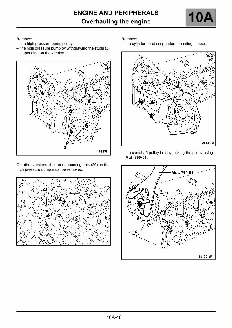
10A-48
Remove:– the high pressure pump pulley,– the high pressure pump by withdrawing the studs (3)
depending on the version.
On other versions, the three mounting nuts (20) on the high pressure pump must be removed.
Remove:– the cylinder head suspended mounting support,
– the camshaft pulley bolt by locking the pulley using Mot. 799-01.

ENGINE AND PERIPHERALSOverhauling the engine 10A
10A-49
Remove:– the inner timing cover,
– the ring for lifting the engine at the flywheel end,– the pre-post heating plugs using a 10 mm articulated
wrench,
– the vacuum pump,– the thermostatic unit,
– the cylinder head cover.
ENGINE AND PERIPHERALSOverhauling the engine 10A
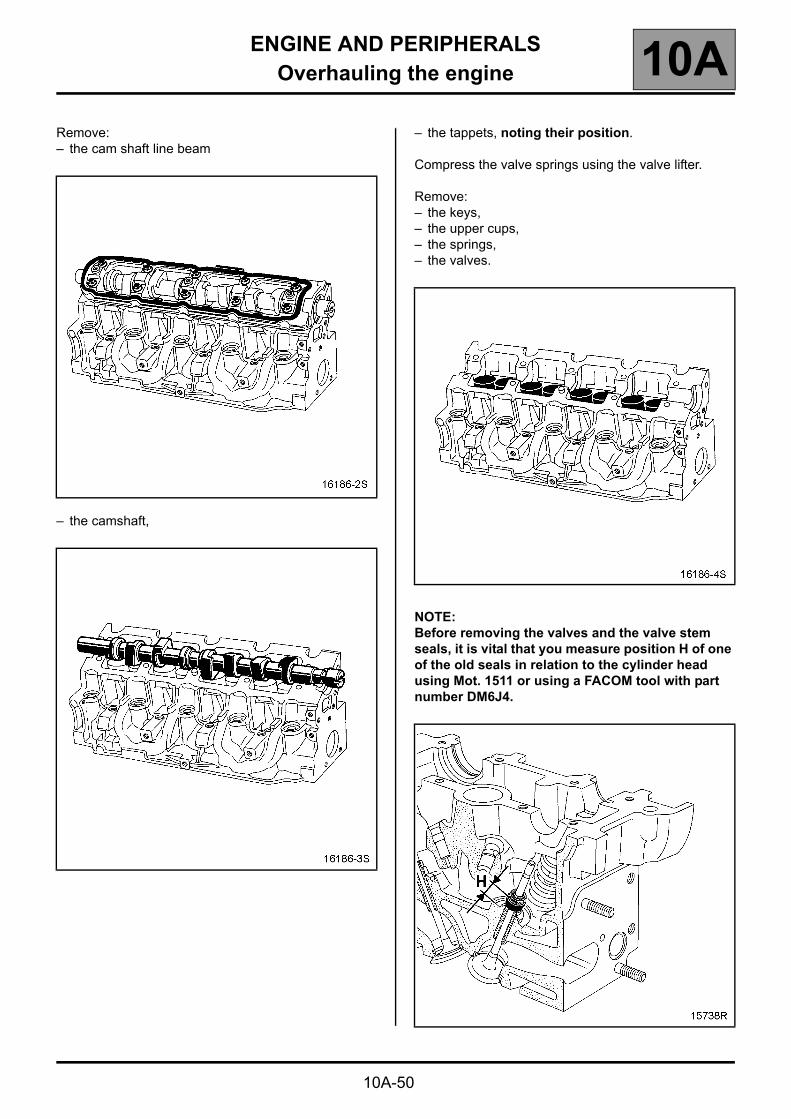
10A-50
Remove:– the cam shaft line beam
– the camshaft,
– the tappets, noting their position.
Compress the valve springs using the valve lifter.
Remove:– the keys,– the upper cups,– the springs,– the valves.
NOTE:Before removing the valves and the valve stem seals, it is vital that you measure position H of one of the old seals in relation to the cylinder head using Mot. 1511 or using a FACOM tool with part number DM6J4.

ENGINE AND PERIPHERALSOverhauling the engine 10A
10A-51
Fit the pushrod of Mot. 1511 on the valve stem seal.
NOTE:The internal diameter of the pushrod must be identical to that of the valve. Moreover, the pushrod must come into contact with the metallic upper section of the valve stem seal.
Fit the guide tube above the pushrod until it comes into contact with the cylinder head.
Insert sleeve (1) in the guide tube, until the sleeve comes into contact with the pushrod.
Then block the sleeve using the wheel (2).
Remove the guide tube plus sleeve assembly, being careful not to loosen the tumblewheel.
Withdraw the pushrod.
Remove:– the valve stem seals using pliers Mot. 1335,– the lower cups.

ENGINE AND PERIPHERALSOverhauling the engine 10A
10A-52
CLEANING
It is very important not to scratch the mating surfaces of any aluminium components.
Wear gloves whilst carrying out this operation.
Use "Décapjoint" product or equivalent to dissolve any part of the gasket remaining stuck.
Apply the product to the section to be cleaned.
Wait for about ten minutes, then remove using a wooden spatula.
Do not allow this product to drip on to the paintwork.
Great care should be taken when performing this operation, to prevent foreign objects entering the pipes taking oil under pressure to the camshafts (pipes in both the cylinder head and its cover) and the oil return pipes.
CHECKING THE GASKET FACE
Check for mating surface bow using a ruler and a set of shims.
Maximum bow 0.05 mm.
NO REGRINDING OF THE CYLINDER HEAD IS PERMITTED
CHECKING THE CAMSHAFT END PLAY
Refit the camshaft.
Refit the camshaft line beam by tightening the bolts to a torque of 2 daN.m.
Check the end play, which must be between 0.045 and 0.135 mm.
Remove the camshaft line beam and the camshaft.
Check that the cylinder head lubrication ducts, camshaft bearings, and tappets are not obstructed.
Replace worn parts.

ENGINE AND PERIPHERALSOverhauling the engine 10A
10A-53
REBUILDING THE CYLINDER HEAD
Fit new valves, grind them gently into their respective seats.
Clean all the parts thoroughly, mark them for identification purposes, then carry out the refitting operation.
Lubricate the inside of the valve guide.
Fit the valve spring collar rings.
The valve stem seals must be fitted using tool Mot. 1511 or with the FACOM tool, part number DM6J4.
NOTE:Do not lubricate the valve stem seals before fitting them.
Fitting new valve stem seals.
Place the valve in the cylinder head.
Place the barrel of the Mot. 1511 tool over the valve stem (the internal diameter of the barrel must be identical to the diameter of the valve stem).
Keep the valve pressed against its seat.
Place the valve stem seal (not lubricated) over the tool barrel.

ENGINE AND PERIPHERALSOverhauling the engine 10A
10A-54
Push the valve stem seal past the tool barrel, then withdraw the barrel.
Place the pushrod over the valve stem seal.
NOTE:The internal diameter of the pushrod must be identical to the diameter of the valve stem.
Moreover, the lower part of the pushrod must be in contact with the upper section of the valve stem seal.
Place the guide tube and sleeve assembly over the pushrod.

ENGINE AND PERIPHERALSOverhauling the engine 10A
10A-55
Push the valve stem seal down by tapping the top of the sleeve with the palm of your hand until the guide tube touches the cylinder head.
Repeat these operations for all the valves.
Position the springs.
Position the upper cups.
Compress the springs.
Fit the pins.
Check the valve protrusion which should be 0.09 ± 0.12 mm.
Check and adjust the valve clearance
Refit the tappets.
Refit the camshaft.
Refit the camshaft line beam by tightening it to a torque of 2 daN.m.
Place the valves of the cylinder concerned at the "end of exhaust - beginning of inlet" position and check the clearance (X).
NOTE: Dimension (Y) corresponds to the tappet thickness class (there are 25 classes in the Parts Store).
Compare the values noted with the specified values.
Clearance, when the engine is cold, in mm:Inlet 0.20 ± 0.05Exhaust 0.40 ± 0.05
Remove:– the cam shaft line beam– the camshaft,– the tappet(s) not within tolerance.
Y X
1342
4213

ENGINE AND PERIPHERALSOverhauling the engine 10A
10A-56
Determining dimension (Y).
Set up the following assembly using Mot. 252-01 and Mot. 856-02, then calibrate the gauge.
Raise the gauge extension (without modifying the position of the magnetic support/gauge assembly), then slide in the tappet to be measured.
Note dimension (Y) and repeat the operation for the tappets where the valve clearance is not within tolerance.
Then select the various thicknesses of the tappet(s) by referring to the "Replacement parts catalogue" for the vehicle concerned.
Lubricate the camshaft bearings.
Degrease the mating faces, which they must be clean, dry and free from grease (in particular, avoid finger marks).
Fit the camshaft.

ENGINE AND PERIPHERALSOverhauling the engine 10A
10A-57
Using a stipple roller, apply Loctite 518 to the gasket face of the camshaft line beam until it turns "reddish" in colour.
NOTE:Using a cloth, remove any LOCTITE 518 in the five camshaft line beam bearings.
Place one or two drops of LOCTITE FRENETANCH on the five beam mounting bolts on the inlet and exhaust manifold end.
Tighten the camshaft line beam to a torque of 2 daN.m, in the specified sequence.
Degrease the mating faces of the cylinder head cover and the camshaft line beam. They must be clean, dry and free from grease (in particular, avoid finger marks).
Refit the new seal on the cylinder head cover.
Refit the cylinder head cover by tightening the bolts in the specified sequence:● tighten bolt (1) to a torque of 1.2 daN.m,● tighten bolts (2) and (3) to a torque of 1.2 daN.m,● retighten bolt (1) to a torque of 1.2 daN.m.

ENGINE AND PERIPHERALSOverhauling the engine 10A
10A-58
Refit:– the thermostatic support fitted with a new seal by
tightening the bolts to a torque of 0.8 daN.m,– the vacuum pump by tightening the bolts to a torque
of 2.3 daN.m,
– the engine lifting ring (flywheel end) by tightening the bolts to a torque of 1.3 daN.m,
– the pre-postheating plugs using an articulated wrench of 10 mm by tightening them to a torque of 1.5 daN.m,
– the inner timing housing by placing a drop of LOCTITE FRENETANCH on the bolts, then tightening them to a torque of 1 daN.m,
– the camshaft seal (timing end) using Mot. 988-02.

ENGINE AND PERIPHERALSOverhauling the engine 10A
10A-59
Refit:– the camshaft pulley by blocking it using Mot. 799-01,
and tightening the bolt to a torque of 6 daN.m,
– the cylinder head suspended mounting, tightening the bolts to a torque of 3.5 daNm,
– the high pressure pump by tightening the studs to a torque of 3 daN.m,
– the high pressure pump pulley, locking it using tool Mot. 1200-01 or Mot. 1200-02. Tighten the nut to a torque of 1.5 daN.m plus an angle of 60° ± 10°.

ENGINE AND PERIPHERALSOverhauling the engine 10A
10A-60
Change the washer (1) under the injectors.
NOTE:In order to refit the high pressure pipes correctly, it is vital that the following fitting sequence be complied with.
Refit:– the injectors,– the injector brackets without blocking them,– the two rail bolts without blocking them,– the new diesel return pipe.
Tighten the injector flanges to a torque of 2 daN.m.
Refit the high pressure pipes.
Tighten:– the high pressure pipe nuts at the injector end to a
torque of 2.5 daN.m,– the high pressure pipe nuts at the rail end to a
torque of 2.5 daN.m,– the rail tightening bolts to a torque of 2.2 daN.m,– the pump/rail high pressure pipe to a torque of
2.5 daN.m.
Bring the support into contact with the rear of the pump using the two nuts (1).
Tighten the two bolts (2), then the two nuts (1) to a torque of 3 daN.m.

ENGINE AND PERIPHERALSOverhauling the engine 10A
10A-61
REMOVING THE LOWER ENGINE
Engine fitted with a water pump driven by the timing belt.
Remove:– the power-assisted steering
pump,– the accessories tensioner roller
by removing bolt (1),
– the alternator.

ENGINE AND PERIPHERALSOverhauling the engine 10A
10A-62
Remove:– the air conditioning compressor,
– the multifunction mounting.

ENGINE AND PERIPHERALSOverhauling the engine 10A
10A-63
Remove:– the oil decanter,– the oil filter,– the oil heat exchanger,– the oil pressure sensor,– the oil level sensor,– the coolant hose,– the pump inlet pipe.
– the clutch
Checking the flywheel and the friction face
It is essential to change the flywheel is the contact surface is "bluish" or if the friction face is "worn out".
Position the immobilising tool Mot. 582-01 or Mot. 1677.
Remove the flywheel mounting bolts (these bolts must be replaced).
Remove the flywheel.

ENGINE AND PERIPHERALSOverhauling the engine 10A
10A-64
Special notes concerning engines fitted with a flexible flywheel:
Under no circumstances should the bolts (A) be removed.
Remove:– the engine oil sump,
– the oil pump and the anti emulsion panel,
– the timing tensioner plate,– the coolant pump.

ENGINE AND PERIPHERALSOverhauling the engine 10A
10A-65
Remove the timing crankshaft sprocket.
If necessary, use the locally manufactured tool (see drawing on following page) with the thrust plate Rou. 15-01.

ENGINE AND PERIPHERALSOverhauling the engine 10A
10A-66
Drawing of locally manufactured tool (dimensions in mm)
A Two holes, 6.5 mmB Bolts, ∅ 12 mm - pitch 1.75 mmC One hole, ∅ 13 mmD Nut, ∅ 12 mm - pitch 1.75 mm weld-on
ENGINE AND PERIPHERALSOverhauling the engine 10A
10A-67
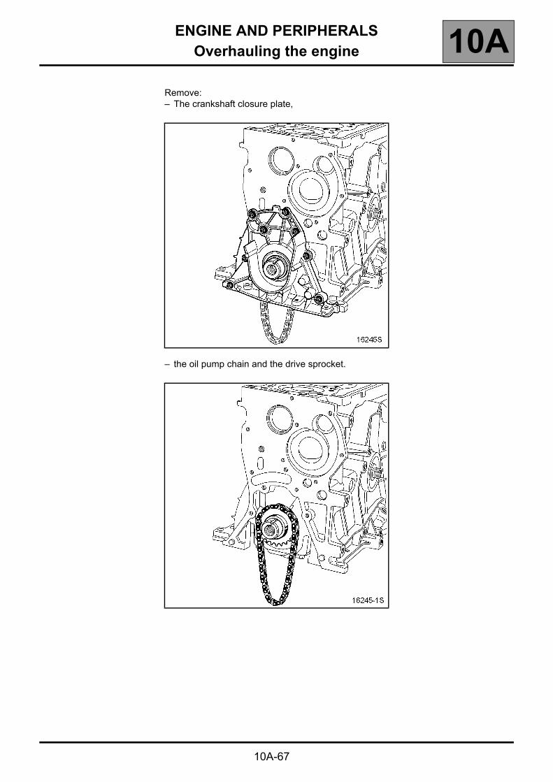
Remove:– The crankshaft closure plate,
– the oil pump chain and the drive sprocket.

ENGINE AND PERIPHERALSOverhauling the engine 10A
REMOVING THE LOWER ENGINE
IMPORTANT:Do not use a sharp point to mark the bearing caps in relation to their con rods to avoid starting a crack in the rod.
Use a permanent marker pen.
10A-68

ENGINE AND PERIPHERALSOverhauling the engine 10A
10A-69
Remove the bearing caps and the connecting rod/piston assemblies.
NOTE:It is essential to mark the position of the crankshaft shells, as the category may be different for each bearing.
Remove:– the crankshaft bearing caps,– oil return tube (1) from the
decanter by tapping (A).
ENGINE AND PERIPHERALSOverhauling the engine 10A
10A-70
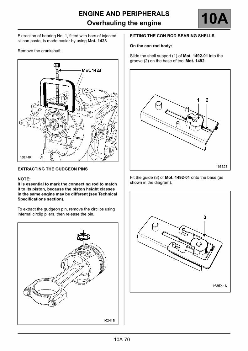
Extraction of bearing No. 1, fitted with bars of injected silicon paste, is made easier by using Mot. 1423.
Remove the crankshaft.
EXTRACTING THE GUDGEON PINS
NOTE:It is essential to mark the connecting rod to match it to its piston, because the piston height classes in the same engine may be different (see Technical Specifications section).
To extract the gudgeon pin, remove the circlips using internal circlip pliers, then release the pin.
FITTING THE CON ROD BEARING SHELLS
On the con rod body:
Slide the shell support (1) of Mot. 1492-01 into the groove (2) on the base of tool Mot. 1492.
Fit the guide (3) of Mot. 1492-01 onto the base (as shown in the diagram).

ENGINE AND PERIPHERALSOverhauling the engine 10A
10A-71
Lay the body of the con rod on the base of the tool (as shown in the diagram).
Ensure that the lower part (4) of the small end of the con rod is in contact with the guide pin.
Fit the shell (5) on the shell support, then push it in the direction of the arrow (as shown in the diagram).
Bring the shell support up against the base of the con rod body.
Remove the con rod body support and repeat the operation for the remaining con rod bodies.
On the con rod cap
Fit the con rod cap as shown in the diagram.
ENGINE AND PERIPHERALSOverhauling the engine 10A
10A-72
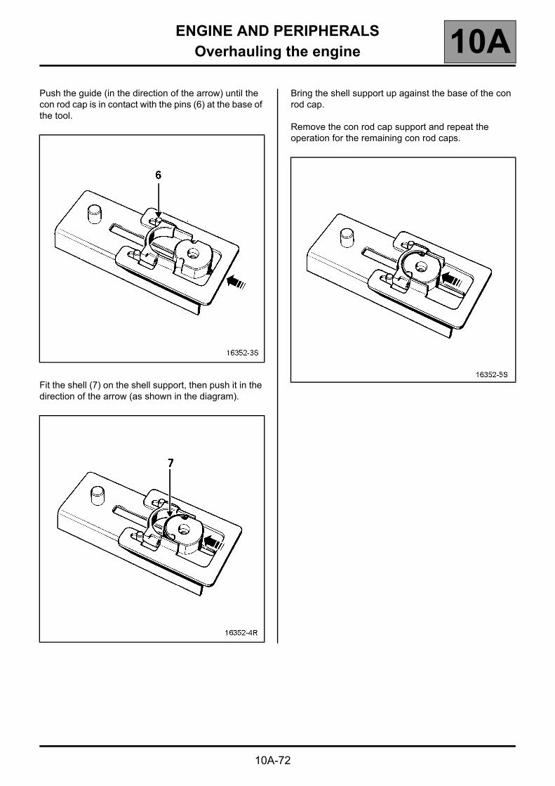
Push the guide (in the direction of the arrow) until the con rod cap is in contact with the pins (6) at the base of the tool.
Fit the shell (7) on the shell support, then push it in the direction of the arrow (as shown in the diagram).
Bring the shell support up against the base of the con rod cap.
Remove the con rod cap support and repeat the operation for the remaining con rod caps.

ENGINE AND PERIPHERALSOverhauling the engine 10A
10A-73
"CON RODS / PISTON" ASSEMBLY
NOTE:You must ensure that you match the con rods to the piston and cylinder as previously determined.
Direction of fitting of the con rod in relation to the piston
Place the "Λ" (1) engraved on the piston head downwards.
Place the machined flat (2) of the con rod head upwards.
Direction for fitting the circlips on the piston
Fit the circlips on the piston as shown below.
FITTING THE RINGS
The rings set to their original adjustment must be free within their channels.
Ensure the rings are fitted in the correct orientation.
T = Top
Fit the rings such that the gaps are equally spaced around the piston.

ENGINE AND PERIPHERALSOverhauling the engine 10A
10A-74
PISTON BASE COOLING JETS
There are various orientations for piston cooling jets (0°, 3° and 5°).
To be sure of obtaining the correct cooling jet orientation when refitting, their orientation must be marked before they are removed.
To do that, use tools Mot. 1516, Mot. 1516-01 and Mot. 1516-02.
Then, try to fit one of the three plates of these tools.
Each plate corresponds to a precise cooling jet orientation.
Replacement of the piston base cooling jets
REMOVAL
To remove the piston base cooling jets (1), they must be drilled with a 7 mm diameter drill. This is necessary in order to remove the spring stop (2) and the spring (3).
NOTE:Do not remove the ball (4), to prevent swarf entering the cooling circuit.
Orientation of cooling jets (in degrees)
Tools to be used for removal (marking the orientation) then for
refitting (application of the correct orientation)
0° Mot. 1516-02
3° Mot. 1516-01
5° Mot. 1516

ENGINE AND PERIPHERALSOverhauling the engine 10A
10A-75
Remove the swarf using a brush.
Screw Mot. 1485 or Mot. 1485-01 into the drilled out jets using a 6 mm Allen key which you slide inside the tool.
ENGINE AND PERIPHERALSOverhauling the engine 10A
10A-76
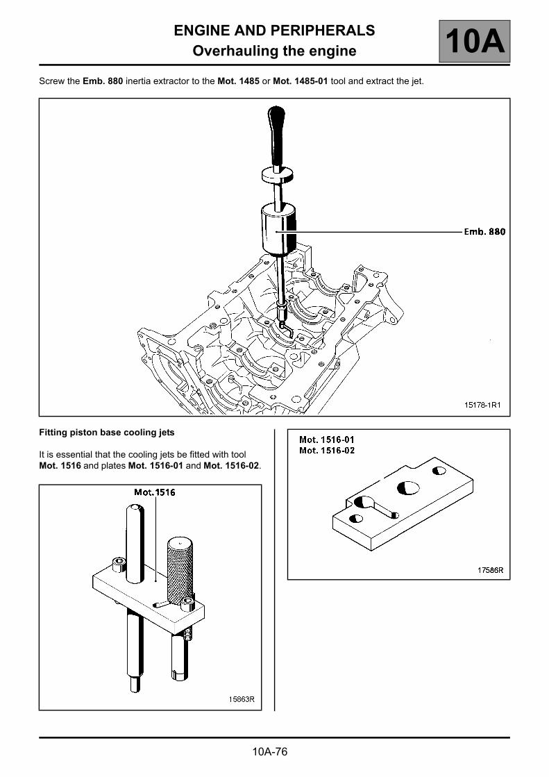
Screw the Emb. 880 inertia extractor to the Mot. 1485 or Mot. 1485-01 tool and extract the jet.
Fitting piston base cooling jets
It is essential that the cooling jets be fitted with tool Mot. 1516 and plates Mot. 1516-01 and Mot. 1516-02.

ENGINE AND PERIPHERALSOverhauling the engine 10A
10A-77
Fitting the jets for cylinders 1 and 3
Locate the plate (3) of the Mot. 1516-01 tool on the cylinder block (as shown in the illustration below) without tightening the two bolts (1) of the Mot. 1516 tool.
Position the guide rod (2) of tool Mot. 1516 in the plate (3) and the end of the guide rod in the cooler hole to centre the plate (3).
Tighten the two bolts (1), the remove the guide rod.
Insert the cooler into the pushrod.
NOTE:Check that the jet is correctly oriented, with the end of the jet (4) directed towards the centre of the cylinder.
Fit the pushrod in place and instead of the guide rod.
With a hammer, tap the pushrod until the shoulder (5) of the pushrod comes into contact with the plate (3).

ENGINE AND PERIPHERALSOverhauling the engine 10A
10A-78
Fitting the jets for cylinders 2 and 4
Locate the plate (3) of the Mot. 1516-01 tool on the cylinder block (as shown in the illustration below) without tightening the two bolts (1) of the Mot. 1516 tool.
Position the guide rod (2) of tool Mot. 1516 in the plate (3) and the end of the guide rod in the cooler hole to centre the plate (3).
Tighten the two bolts (1), the remove the guide rod.
Insert the cooler into the pushrod.
NOTE:Check that the jet is correctly oriented, with the end of the jet (4) directed towards the centre of the cylinder.
Fit the pushrod in place and instead of the guide rod.
With a hammer, tap the pushrod until the shoulder (5) of the pushrod comes into contact with the plate (3).

ENGINE AND PERIPHERALSOverhauling the engine 10A
10A-79
Orientation of the piston base cooling jets (see diagram below).
A: Orientation of the coolers of cylinders 2 and 4B: Orientation of the coolers of cylinders 1 and 3

ENGINE AND PERIPHERALSOverhauling the engine 10A
10A-80
REFITTING THE LOWER ENGINE
Clean the cylinder block.
Clean the crankshaft by passing a wire through the lubrication channels.
Fitting the metal oil return pipe from the decanter
The pipe is fitted using Mot. 1551.
Fit the base (1) of Mot. 1551 on the cylinder block (as shown in the diagram).
Slide the pipe (2) into the groove of the base of the tool.
Fit the snap fastener on the pipe collar.

ENGINE AND PERIPHERALSOverhauling the engine 10A
10A-81
Tap the snap fastener using a hammer until the shoulder (3) of the snap fastener touches the base of the tool (1).
Fitting the bearings in the cylinder block
Position tool Mot. 1493 on the cylinder block.
Fit the grooved bearing shell in tool Mot. 1493, then press at (A) until the bearing shell is touching tool Mot. 1493 at (B).

ENGINE AND PERIPHERALSOverhauling the engine 10A
10A-82
Fitting the bearing shells in the bearings
Position tool Mot. 1493 on the bearing.
Fit the non-grooved bearing shell in tool Mot. 1493, then press at (C) until the bearing shell is touching tool Mot. 1493 at (D).
Replacement of the crankshaft bearing
The crankshaft bearing is extracted using Mot. 11.

ENGINE AND PERIPHERALSOverhauling the engine 10A
10A-83
Refit:– the lateral crankshaft shims,– the crankshaft.
Oil the main journal bearings with engine oil.
Refit the crankshaft bearing caps except cap N° 1 (the caps are numbered from 1 to 5 and position these numbers opposite the oil filter side).
Tighten the bolts to a torque of 2 daN.m plus an angle of 62° ± 4° (tightening order 3 4 2 5 1).

ENGINE AND PERIPHERALSOverhauling the engine 10A
10A-84
Check the lateral clearance of the crankshaft which should be between 0.067 and 0.233 mm.
Check that the crankshaft rotates freely.
Fitting bearing N° 1 with silicon injection
IMPORTANT: the mixture must be injected within approximately 5 minutes to prevent it from polymerising in the syringe.
Clean the surfaces thoroughly at (25) of the cylinder block and the crankshaft cap, using a cloth soaked in cleaning thinner.
Allow to dry.
Coat the lower surfaces of the cylinder block at (26) with a thin layer of RHODORSEAL 5661.
Install the crankshaft bearing cap and tighten it to a torque of 2 daN.m plus an angle of 62° ± 4°.
Mix 45 ml of RHODORSEAL 5661 (approximately half of a 100 gram tube) with half of the tube of hardener using the mixing stick to obtain a uniform, slightly pink mixture.

ENGINE AND PERIPHERALSOverhauling the engine 10A
10A-85
Insert the mixture into the syringe and inject it into the grooves of the crankshaft bearing cap.
Allow the mixture to flow out slightly on either side of the grooves of the crankshaft bearing cap, to ensure that the injected mixture has totally filled the sealing groove.
Using a cloth, wipe off the excess mixture, both inside and outside the cylinder block.
Allow to dry for a few moments and cut the excess off the gasket face.

ENGINE AND PERIPHERALSOverhauling the engine 10A
10A-86
Fitting the pistons
The pistons are fitted using cone Mot. 1569.
Oil the pistons.
Fit the piston in the cone and allow the piston skirt to protrude from the cone by approx. 1 to 2 cm.
ENGINE AND PERIPHERALSOverhauling the engine 10A
10A-87
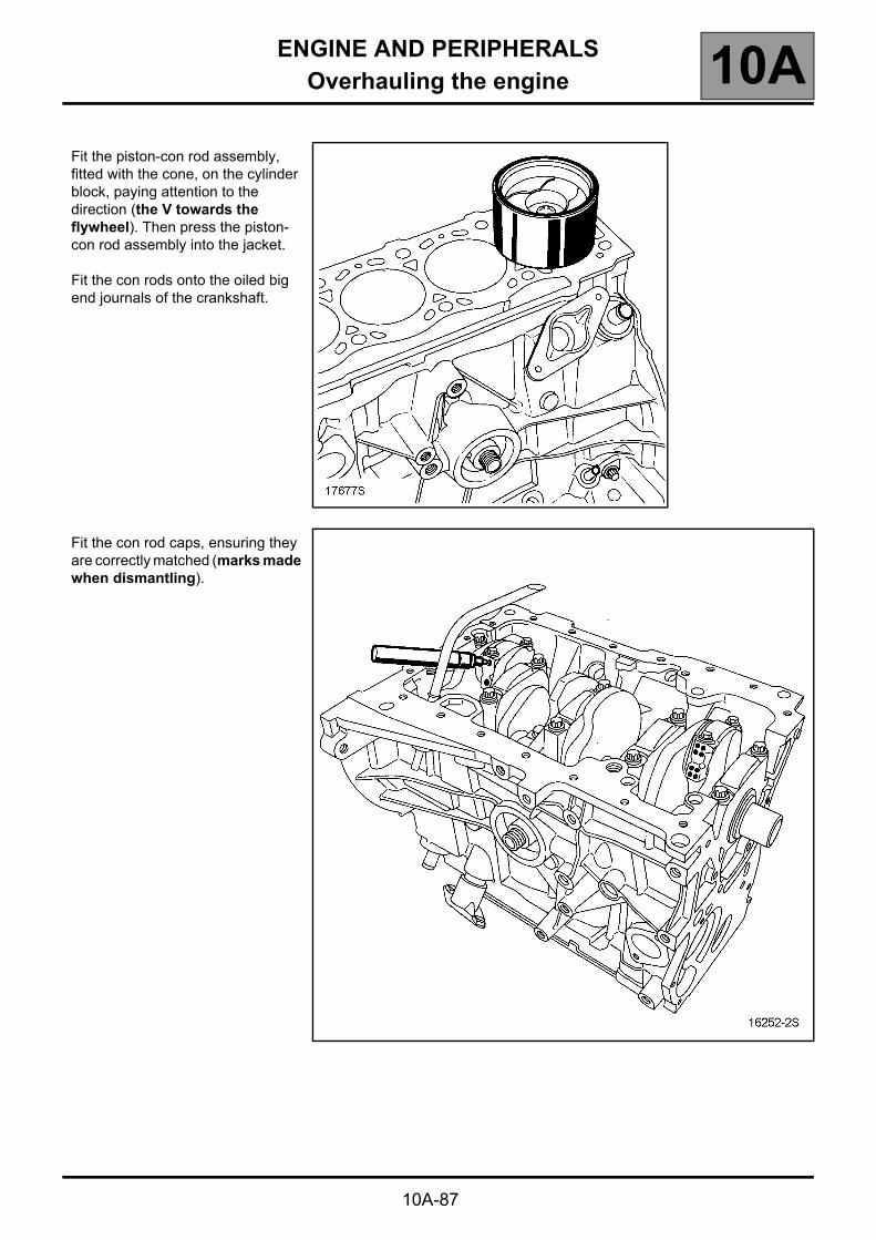
Fit the piston-con rod assembly, fitted with the cone, on the cylinder block, paying attention to the direction (the V towards the flywheel). Then press the piston-con rod assembly into the jacket.
Fit the con rods onto the oiled big end journals of the crankshaft.
Fit the con rod caps, ensuring they are correctly matched (marks made when dismantling).

ENGINE AND PERIPHERALSOverhauling the engine 10A
10A-88
Tighten the new bolts of the con rod caps to a torque of 2 daN.m, then tighten to an angle of 40° ± 6°.
Check the lateral clearance of the con rod head, which should be between 0.22 and 0.482 mm.

ENGINE AND PERIPHERALSOverhauling the engine 10A
10A-89
Checking piston protrusion
Clean the piston heads in order to eliminate any traces of deposits.
Turn the crankshaft one turn in its operating direction to bring piston No. 1 close to top dead centre.
Fit tool Mot. 252-01 on the piston.
Fit tool Mot. 251-01 equipped with a gauge on its base plate Mot. 252-01, and find top dead centre of the piston.
NOTE:All measurements are to be carried out in the longitudinal axis of the engine, in order to eliminate any errors due to tilting of the piston.
WARNING:the gauge detector must not be in the valve clearance.
Measure the piston protrusion.
The protrusion must be: 0.56 ± 0.06 mm.
NOTE:To prevent any risk of piston/valve interference when the engine is running, the piston protrusion value must be less than 0.67 mm.
Refit the oil pump chain.

ENGINE AND PERIPHERALSOverhauling the engine 10A
10A-90
Crankshaft closure panel sealing
There are two possible solutions:● Either it is sealed with RHODORSEAL 5661; the
band (1) must be 1.75 mm wide and be applied as shown in the drawing below.Be careful not to obstruct the pipes (C).
● Or it is performed with a seal consisting of a steel sheet coated with elastomer on both sides.NOTE:This type of seal projects from the plate. It should in no case be cut out, because the two projecting tabs provide sealing when the sump is fitted.
Oil pump chain guide
There are likewise two possible solutions:
For engines equipped with a water pump driven by the timing belt (water pump moved).
In this case, check presence of oil pump chain guide.
For engines equipped with a water pump driven by the accessories belt (water pump not moved).
In this case, the oil pump chain guide is no longer of any use.

ENGINE AND PERIPHERALSOverhauling the engine 10A
10A-91
Refit the closure panel, tightening the bolts to a torque of 1.4 daN.m.
ENGINE AND PERIPHERALSOverhauling the engine 10A
10A-92
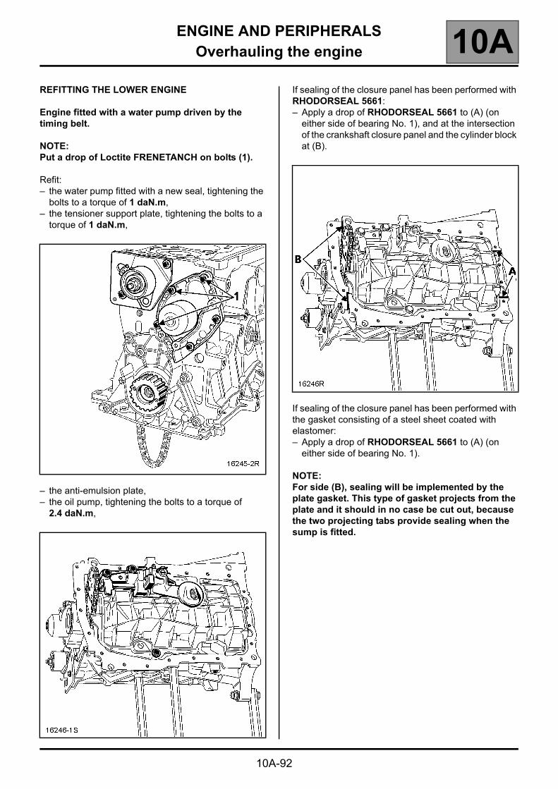
REFITTING THE LOWER ENGINE
Engine fitted with a water pump driven by the timing belt.
NOTE:Put a drop of Loctite FRENETANCH on bolts (1).
Refit:– the water pump fitted with a new seal, tightening the
bolts to a torque of 1 daN.m,– the tensioner support plate, tightening the bolts to a
torque of 1 daN.m,
– the anti-emulsion plate,– the oil pump, tightening the bolts to a torque of
2.4 daN.m,
If sealing of the closure panel has been performed with RHODORSEAL 5661:– Apply a drop of RHODORSEAL 5661 to (A) (on
either side of bearing No. 1), and at the intersection of the crankshaft closure panel and the cylinder block at (B).
If sealing of the closure panel has been performed with the gasket consisting of a steel sheet coated with elastomer:– Apply a drop of RHODORSEAL 5661 to (A) (on
either side of bearing No. 1).
NOTE:For side (B), sealing will be implemented by the plate gasket. This type of gasket projects from the plate and it should in no case be cut out, because the two projecting tabs provide sealing when the sump is fitted.

ENGINE AND PERIPHERALSOverhauling the engine 10A
10A-93
Refit the sump with a new gasket, pre-tightening it to a torque of 0.8 daN.m, then finally tightening it to a torque of 1.5 daN.m in the recommended order.
The alignment of the cylinder block and the sump must be complied with on the flywheel side to prevent the clutch housing from being damaged when fitting the gearbox.
Fitting the crankshaft seal gaskets
GENERAL INFORMATION
Change of material on the engine elastomer seals (fitted on the crankshaft).
Fitting and removing the new type elastomer seal from the engine requires new tools and precautions compared to the old type seal.
The old and new type of seal can both be used on the same engine. They are not interchangeable. Old type seals must be replaced with old type seals (still available from the Parts Department), and a new type seal with a new type seal.
An old type seal can be replaced with a new type seal in the case of a crankshaft replacement. This is possible if the engine is fitted with one during its lifetime in series production.

ENGINE AND PERIPHERALSOverhauling the engine 10A
10A-94
Old and new seals are easily recognized.
The old elastomer seal is fitted with a spring (1) and has a "V"-shaped sealing lip (2).
The new elastomer seal has a flat sealing lip (3) and a protector (4) which also assists in fitting the seal to the engine.

ENGINE AND PERIPHERALSOverhauling the engine 10A
10A-95
Tooling required for fitting old type elastomer seals.
Tooling required for fitting new type elastomer seals.
Tooling required for removing new type elastomer seals.
Engine type Tool for the crankshaft seal
Timing end Flywheel end
F9Q Mot. 990-03 Mot. 991-01
Engine type Tool for the crankshaft seal
Timing end Flywheel end
F9Q Mot. 1636 Mot. 1635
Engine type Tool for the crankshaft seal
Timing end Flywheel end
F9Q Mot. 1577 Mot. 1579

ENGINE AND PERIPHERALSOverhauling the engine 10A
10A-96
Method for removing elastomer seals
This procedure is applicable for crankshaft seals.
Fit the extractor tool onto the shaft by adjusting plungers (1) to the shaft diameter with knurled back-plate (2).
Tighten knurled back-plate (3) until it locks on knurled back-plate (2) to keep the plungers correctly adjusted on the shaft.
Screw extractor tool into the seal using hexagon bar (4).
Extract the seal by tightening threaded rod (5).

ENGINE AND PERIPHERALSOverhauling the engine 10A
10A-97
Method for fitting new type elastomer seals.
IMPORTANT:This type of seal is extremely FRAGILE. Only touch the protector part (1) when handling the gasket. It is strictly forbidden to touch the seal (2). This is to ensure that there will be no oil leaks once the gasket is fitted on the engine.
This new seal must be fitted using the tooling mentioned previously.
Crankshaft elastomer seal (timing end)
Screw the threaded rod (22) of Mot. 1636 into the crankshaft.
Fit spacer (23) of Mot. 1636 to the crankshaft.

ENGINE AND PERIPHERALSOverhauling the engine 10A
10A-98
Fit the protector complete with the seal onto the spacer, taking care not to touch the seal.
Fit cup (24) and nut (25) (putting threaded hole (26) of the nut on the side facing away from the engine) of Mot. 1636.
Tighten the nut until the cover touches the spacer.
Remove the nut, the cup, the protector, the spacer and the threaded rod.
ENGINE AND PERIPHERALSOverhauling the engine 10A
10A-99
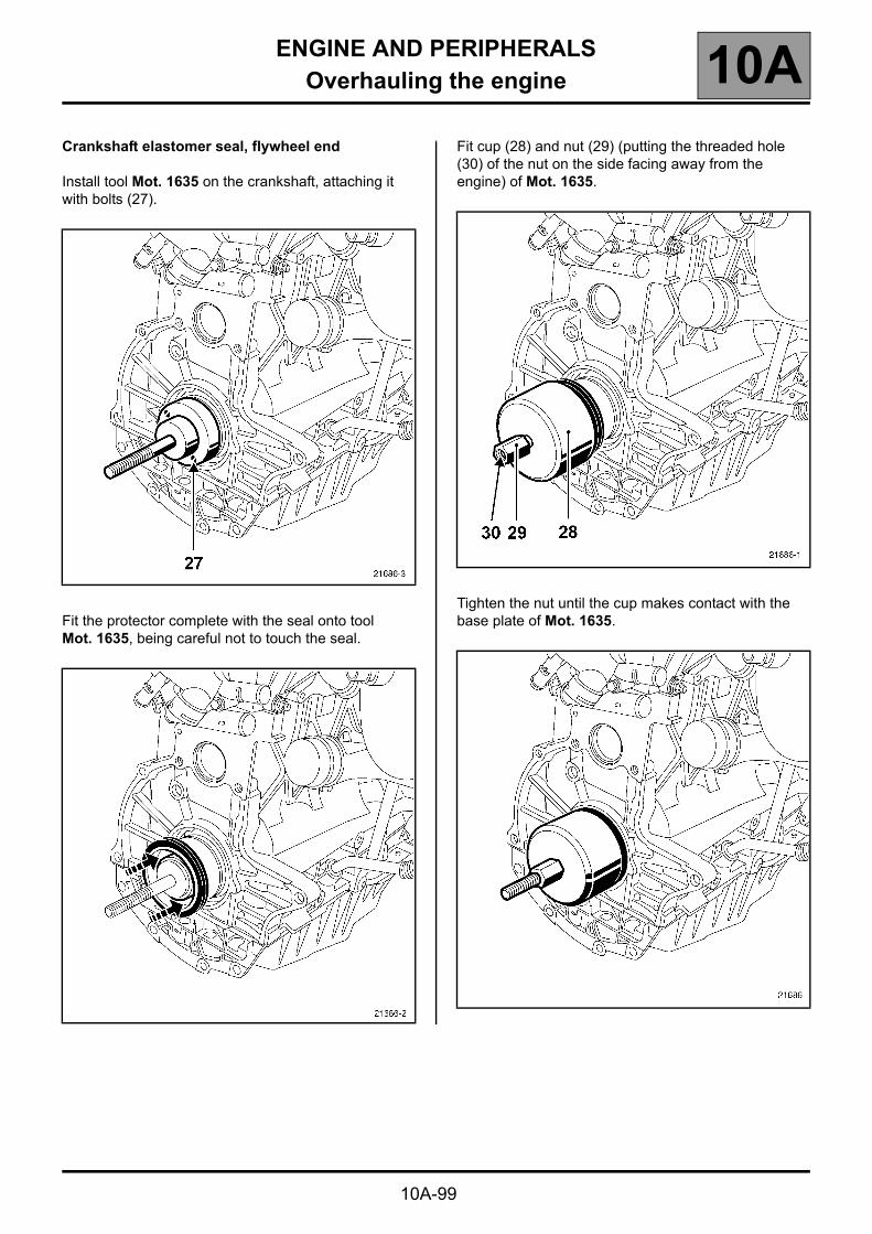
Crankshaft elastomer seal, flywheel end
Install tool Mot. 1635 on the crankshaft, attaching it with bolts (27).
Fit the protector complete with the seal onto tool Mot. 1635, being careful not to touch the seal.
Fit cup (28) and nut (29) (putting the threaded hole (30) of the nut on the side facing away from the engine) of Mot. 1635.
Tighten the nut until the cup makes contact with the base plate of Mot. 1635.

ENGINE AND PERIPHERALSOverhauling the engine 10A
10A-100
The method for fitting old type seals remains unchanged.
Fitting old type crankshaft seal gaskets– Flywheel side, use tool Mot 991-01,
– Timing side, use tool Mot. 990-03.
Lock the flywheel with tool Mot. 582-01 or Mot. 1677 depending on the cylinder block (large or small side).
Refit the flywheel, tightening the new bolts to a torque of 2 daN.m, then tighten to an angle of 70° ± 7°.
If the flywheel is flexible, tighten the new type bolts to a torque of 3 daN.m et then turn them through an angle of 35° ± 6°.
Flexible flywheel:
NOTE:Under no circumstances should bolts (A) be removed.

ENGINE AND PERIPHERALSOverhauling the engine 10A
10A-101
Refit the clutch, tightening the bolts to a torque of 2 daN.m.
Withdraw the flywheel immobiliser Mot. 582-01 or Mot. 1677.

ENGINE AND PERIPHERALSOverhauling the engine 10A
10A-102
Refit:– the oil decanter fitted with a new seal by tightening
the bolts to a torque of 1 daN.m,– the oil heat exchanger,– the oil filter,– the oil pressure sensor by tightening to a torque of
3.8 daN.m,– the oil level sensor by tightening it to a torque of
3 daN.m,– the coolant pipe by tightening the bolt to a torque of
4 daN.m,– the coolant pump inlet pipe fitted with a new seal, by
tightening the bolts to a torque of 1 daN.m,
– the multifunction support by tightening the bolts to a torque of 5 daN.m,

ENGINE AND PERIPHERALSOverhauling the engine 10A
10A-103
Refit:– the air conditioning compressor,
tightening the bolts to a torque of 2.5 daN.m,
– the alternator, tightening the bolts to a torque of 2.5 daN.m.

ENGINE AND PERIPHERALSOverhauling the engine 10A
10A-104
Refit:– the power assisted steering pump
by tightening the bolts to a torque of 2.5 daN.m,
– the accessories roller tensioner by tightening the bolts to a torque of 2.5 daN.m.

ENGINE AND PERIPHERALSOverhauling the engine 10A
10A-105
REFITTING THE UPPER ENGINE
Refitting the cylinder head
Position the pistons at mid-stroke.
Fit the cylinder head gasket using the centring sockets of the cylinder block.
Tighten the cylinder head (see the Cylinder head characteristics).
Timing adjustment
Check that pin Mot. 1054 is in place.
The notch (4) in the crankshaft must be located in the middle of the two grooves (2) on the crankshaft closure housing. The mark (3) of the crankshaft timing sprocket should be moved to the left by one notch of the engine vertical axis.
Check that the tensioner is securely positioned on the pin (1).
Fit the timing belt, aligning the marks on the belt with the marks on the camshaft and crankshaft sprockets (77 teeth between the two marks on the belt).

ENGINE AND PERIPHERALSOverhauling the engine 10A
10A-106
Place the tensioner against the belt by tightening bolt (2) on the tensioner mounting.

ENGINE AND PERIPHERALSOverhauling the engine 10A
10A-107
Remove pin Mot. 1054.
Fit the crankshaft accessories pulley bolt.
IMPORTANT:If the bolt is not fitted with a washer, fit the washer R1 (4) included in the tool kit Mot. 1543.
Do not forget to remove it again when fitting the crankshaft pulley.

ENGINE AND PERIPHERALSOverhauling the engine 10A
10A-108
Fit Mot. 1543 and the cover numbered 1 on the crankshaft accessories pulley bolt.
Apply pre-tension between the crankshaft timing sprocket and the tensioner using the tool Mot. 1543 and the cover 1, adjusting the torque wrench to a torque of 1.1 daNm.

ENGINE AND PERIPHERALSOverhauling the engine 10A
10A-109
Check
Refit pin Mot. 1054 and set the timing to its setting point, (begin to press on the pin a half-tooth before alignment of the mark on the camshaft pulley and that made by the operator on the lower timing housing, to avoid it falling into a crankshaft balance hole).
Remove the pin Mot. 1054.
Apply pretension between the crankshaft timing sprocket and the tensioner using the tool Mot. 1543 and the cover 1, adjusting the torque wrench to a torque of 1.1 daN.m.
Position the sensor of Mot. 1505.
Check that the tension value is 90 Hz ±3 Hz, otherwise readjust it.
Tighten the tensioner nut to a torque of 5 daN.m.
NOTE:It is essential to tighten the tensioner nut to torque to avoid any loosening which may cause damage to the engine.
IMPORTANT:Remove the washer R1 included in the tool kit Mot 1543 before fitting the crankshaft pulley.
Fit the sensor of Mot. 1505 between the crankshaft sprocket and the tensioner.
Tension the belt by turning bolt (2) until the recommended fitting value 95 Hz ± 3 Hz is obtained.
Tighten the tensioner to a torque of 1 daN.m.
Turn the crankshaft over four times.

ENGINE AND PERIPHERALSOverhauling the engine 10A
10A-110
Refit the camshaft sensor.
Install the flywheel immobiliser Mot. 582-01 or Mot. 1677.

ENGINE AND PERIPHERALSOverhauling the engine 10A
10A-111
Refit the crankshaft accessories pulley by tightening the bolt to a torque of 2 daN.m, then angle tighten to 115° ±15°.
Withdraw the flywheel immobiliser Mot. 582-01 or Mot. 1677.
Refit the timing housing.

ENGINE AND PERIPHERALSOverhauling the engine 10A
10A-112
Refit the accessories belt.
Turn the wrench in a clockwise direction to fit the belt.
The engine must be turned through two revolutions to position the belt correctly.

ENGINE AND PERIPHERALSOverhauling the engine 10A
10A-113
Special notes concerning engines fitted with an auto tensioner.
Position the apertures of the tension wheel end piece on the engine mounting and screw up without tightening the two bolts.
Keep the tension wheel in high position.
Install the belt, ending with the tension wheel.
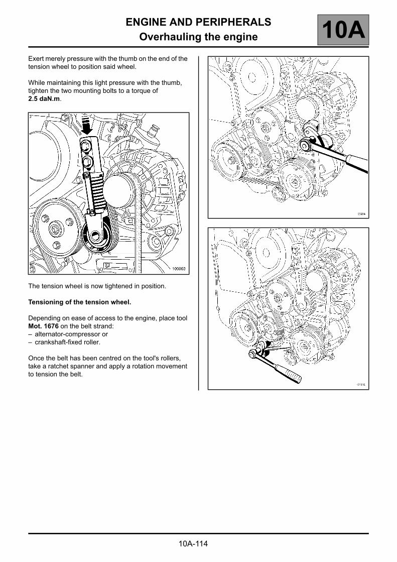
ENGINE AND PERIPHERALSOverhauling the engine 10A
10A-114
Exert merely pressure with the thumb on the end of the tension wheel to position said wheel.
While maintaining this light pressure with the thumb, tighten the two mounting bolts to a torque of 2.5 daN.m.
The tension wheel is now tightened in position.
Tensioning of the tension wheel.
Depending on ease of access to the engine, place tool Mot. 1676 on the belt strand:– alternator-compressor or– crankshaft-fixed roller.
Once the belt has been centred on the tool's rollers, take a ratchet spanner and apply a rotation movement to tension the belt.

ENGINE AND PERIPHERALSOverhauling the engine 10A
10A-115
Maintain the force created by belt torsion until the tension wheel's pretensioning torque plate can be withdrawn manually.
Apply tension to the tension wheel while gradually relaxing the force.
The tension wheel is now ready to operate.

ENGINE AND PERIPHERALSOverhauling the engine 10A
10A-116
REFITTING THE UPPER ENGINE
Refit the inlet and exhaust manifolds fitted with new seals, tightening the nuts to a torque of 2.8 daN.m.
Refit the engine lifting ring, tightening the bolts to a torque of 2 daN.m.
Refit the exhaust gas recirculation pipe.
Remove the engine from the stand Mot. 792-03.

ENGINE AND PERIPHERALSOverhauling the engine 10A
10A-117
Refit the turbocharger, tightening the nuts to a torque of 2.4 daN.m.
Refit the turbocharger oil supply pipe, tightening the couplings at the cylinder block end to a torque of 2.3 daN.m and at the turbocharger end to a torque of 2.4 daN.m.
Refit the turbocharger oil return pipe fitted with new seals, then tighten the bolts to a torque of 1.2 daN.m.
Refit the exhaust stay by tightening the M8 bolt to a torque of 2.4 daN.m and bolt M10 to a torque of 4.3 daN.m.
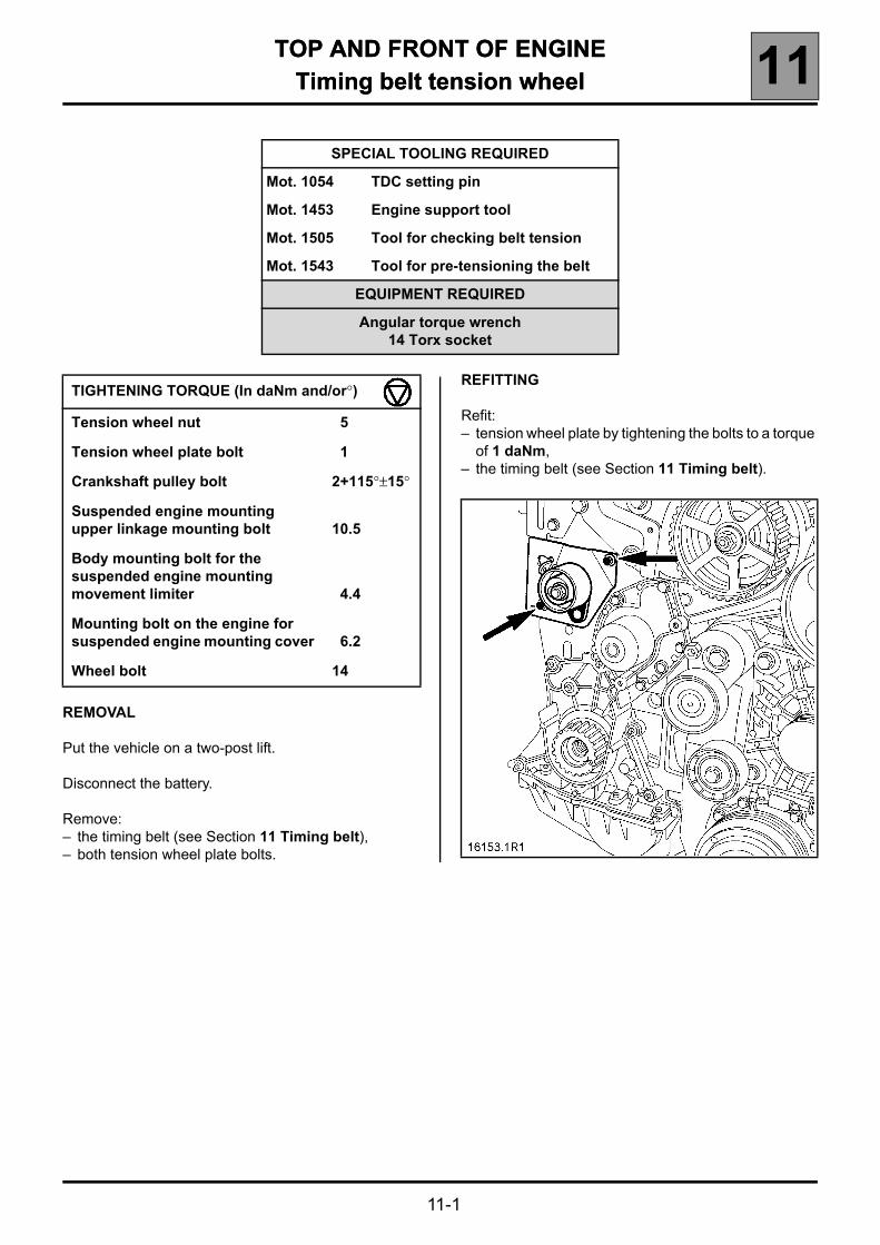
TOP AND FRONT OF ENGINETiming belt tension wheel 11
11-1
111 TOP AND FRONT OF ENGINETiming belt tension wheel
REMOVAL
Put the vehicle on a two-post lift.
Disconnect the battery.
Remove:– the timing belt (see Section 11 Timing belt),– both tension wheel plate bolts.
REFITTING
Refit:– tension wheel plate by tightening the bolts to a torque
of 1 daNm,– the timing belt (see Section 11 Timing belt).
SPECIAL TOOLING REQUIRED
Mot. 1054 TDC setting pin
Mot. 1453 Engine support tool
Mot. 1505 Tool for checking belt tension
Mot. 1543 Tool for pre-tensioning the belt
EQUIPMENT REQUIRED
Angular torque wrench14 Torx socket
TIGHTENING TORQUE (In daNm and/or°)
Tension wheel nut 5
Tension wheel plate bolt 1
Crankshaft pulley bolt 2+115°±15°
Suspended engine mounting upper linkage mounting bolt 10.5
Body mounting bolt for the suspended engine mounting movement limiter 4.4
Mounting bolt on the engine for suspended engine mounting cover 6.2
Wheel bolt 14

TOP AND FRONT OF ENGINETiming belt 11
11-2
Timing belt
REMOVAL
Put the vehicle on four axle stands (see Section 02 Lifting methods for the correct positions of the lifting jack and axle stands) or on a lift.
Disconnect the battery.
NOTE:As the battery is situated under the left-hand seat, the carpet must be removed by unclipping it, then removing the battery flap (A) by undoing the bolts.
Remove the engine undertray and the left-hand side protection.
SPECIAL TOOLING REQUIRED
Mot. 1054 TDC setting pin
Mot. 1505 Tool for checking belt tension
Mot. 1543 Tool for pre-tensioning the belt
Mot. 1367-02 Engine support tool
EQUIPMENT REQUIRED
Angular torque wrench14 Torx socket
TIGHTENING TORQUE (In daNm and/or°)
Tension wheel nut 5
Crankshaft pulley bolt 2+115°±15°
Suspended engine mounting upper linkage mounting bolt 10.5
Body mounting bolt for the suspended engine mounting movement limiter 4.4
Mounting bolt on the engine for suspended engine mounting cover 6.2
Wheel bolt 14

TOP AND FRONT OF ENGINETiming belt 11
11-3
Fit engine support tool Mot. 1367-02 between the lower crossmember and the sub-frame.
Bring the top part of the tool (A) into contact with the sump.
Adjust the position of section (A) on the sump using the mountings (B).
Lift the engine slightly at point (C), then tighten nuts (D).
Unclip the wiring from the engine mounting and move it out of the way.
Unclip the power steering reservoir from its support and remove.
Remove:– the accessories belt (see Section 07 Accessories
belt tension),– tie-rod (1) mounting bolts, then remove the
suspended mounting movement-limiter assembly,
– the Top Dead Centre pin plug.
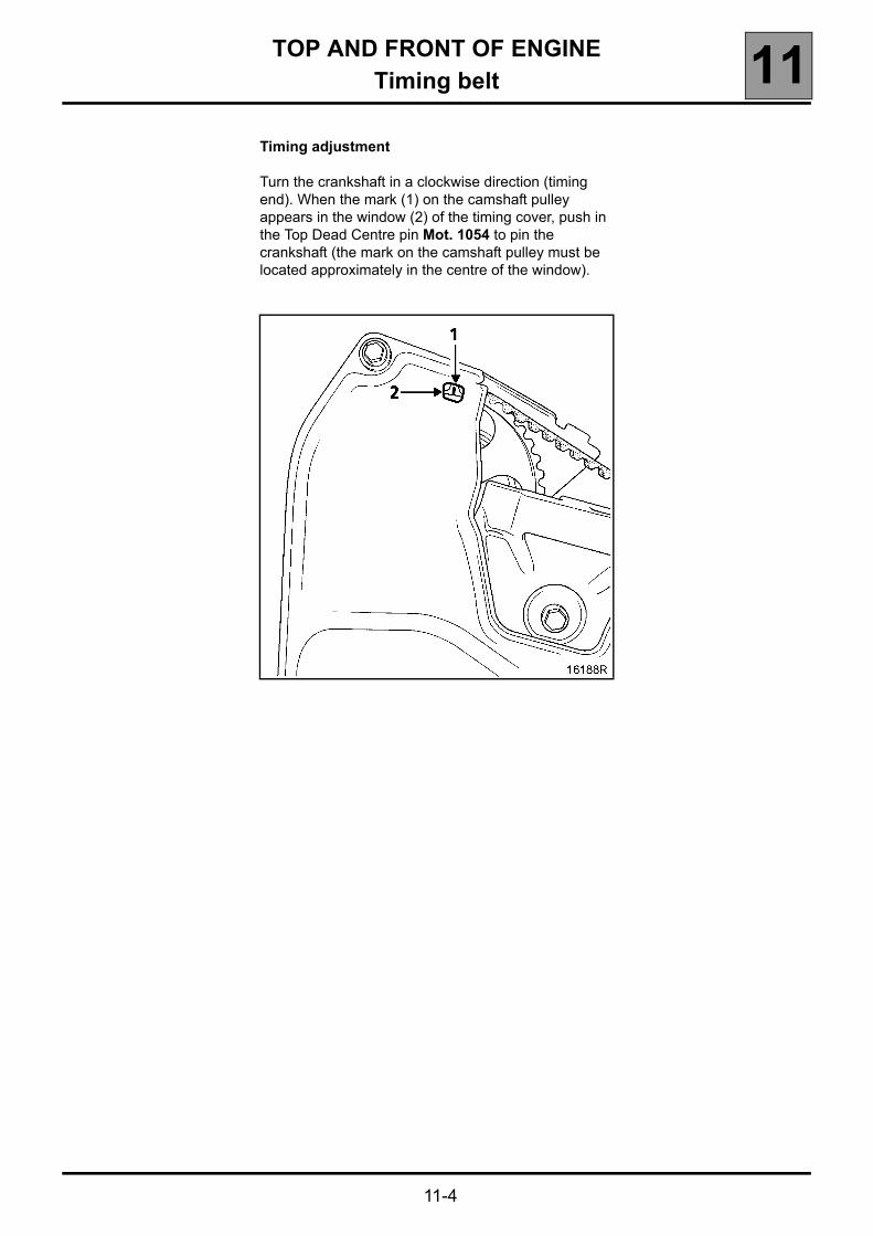
TOP AND FRONT OF ENGINETiming belt 11
11-4
Timing adjustment
Turn the crankshaft in a clockwise direction (timing end). When the mark (1) on the camshaft pulley appears in the window (2) of the timing cover, push in the Top Dead Centre pin Mot. 1054 to pin the crankshaft (the mark on the camshaft pulley must be located approximately in the centre of the window).

TOP AND FRONT OF ENGINETiming belt 11
11-5
Remove:– the accessories belt tensioner (3),– the crankshaft accessories pulley by locking the flywheel,– timing cover from underneath the car (lower the engine using the engine
support tool Mot. 1453).
NOTE:Use a pencil to mark the lower timing housing opposite the mark on the camshaft pulley.

TOP AND FRONT OF ENGINETiming belt 11
11-6
Loosen the tensioner by loosening the nut (5), then remove the timing belt.

TOP AND FRONT OF ENGINETiming belt 11
11-7
REFITTING
TENSIONING PROCEDURE
Engine cold (ambient temperature).
Check that the tensioner is securely positioned on the pin (1).
Check that pin Mot. 1054 is in place.
The crankshaft groove (4) should be located at the centre of the two ribs (2) on the crankshaft closure housing, mark (3) on the crankshaft timing sprocket should be offset one tooth to the left of the vertical axis of the engine.

TOP AND FRONT OF ENGINETiming belt 11
11-8
Fit the new timing belt by aligning the belt markings with those of the camshaft and crankshaft sprockets.
Place the tensioner against the belt by tightening bolt (2) on the tensioner mounting.
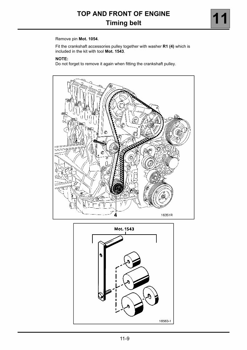
TOP AND FRONT OF ENGINETiming belt 11
11-9
Remove pin Mot. 1054.
Fit the crankshaft accessories pulley together with washer R1 (4) which is included in the kit with tool Mot. 1543.
NOTE:Do not forget to remove it again when fitting the crankshaft pulley.
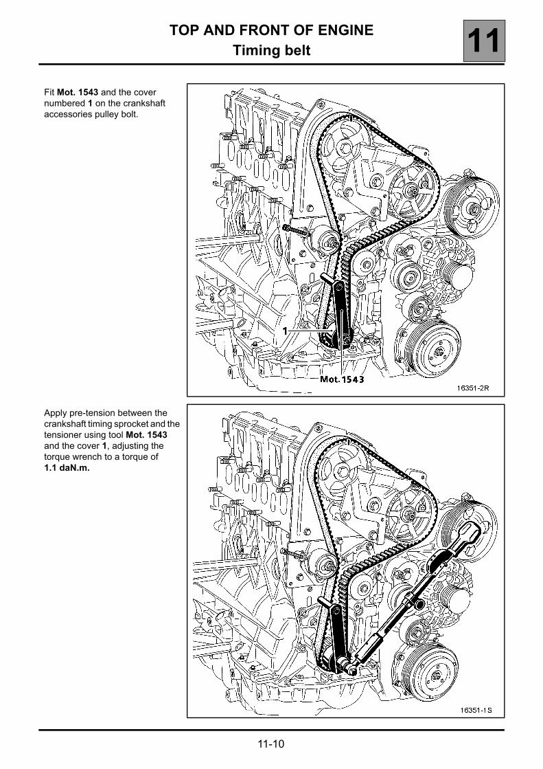
TOP AND FRONT OF ENGINETiming belt 11
11-10
Fit Mot. 1543 and the cover numbered 1 on the crankshaft accessories pulley bolt.
Apply pre-tension between the crankshaft timing sprocket and the tensioner using tool Mot. 1543 and the cover 1, adjusting the torque wrench to a torque of 1.1 daN.m.

TOP AND FRONT OF ENGINETiming belt 11
11-11
Connect the sensor of Mot. 1505.
Tension the belt by turning bolt (2) until the recommended fitting value 95 ± 3 Hz is obtained.
Tighten the tensioner to a torque of 1 daN.m.
Turn the crankshaft two revolutions.
TOP AND FRONT OF ENGINETiming belt 11
11-12
Refit the pin Mot. 1054 and set the timing to its setting point, (begin to press on the pin half a tooth before alignment of the mark on the camshaft pulley and that made by the operator on the inner timing housing, to prevent it falling into a crankshaft balance hole).
Remove pin Mot. 1054.
Apply pre-tension between the crankshaft timing sprocket and the tensioner using the tool Mot. 1543 and the cover 1, adjusting the torque wrench to a torque of 1.1 daN.m.
Position the sensor of Mot. 1505.
Check that the tension value is 90 ± 3 Hz. If not, readjust it.
Tighten the tension wheel nut to a torque of 5 daNm.
NOTE:It is essential to tighten the tensioner nut to torque to avoid any loosening which may cause damage to the engine.
IMPORTANT:Remove the numbered washer R1 included in tool kit Mot. 1543 before fitting the crankshaft pulley.
The crankshaft accessories pulley bolt MUST be tightened to a torque of 2 daNm plus an angle of 115º ± 15º.
Refitting is the reverse of removal.
Refit the right-hand suspended engine mounting (see Section 19 Suspended engine mounting for the tightening torques).

TOP AND FRONT OF ENGINECylinder head gasket 11
11-13
Cylinder head gasket
REMOVAL
Put the vehicle on four axle stands (see Section 02 Lifting methods for the correct positions of the lifting jack and axle stands) or on a lift.
Disconnect the battery.
NOTE:As the battery is located beneath the left seat, the carpet must be removed from the floor by unclipping it, then remove the battery flap (A) by loosening the bolts.
Drain the cooling circuit through the lower radiator hose.
SPECIAL TOOLING REQUIRED
Mot. 1054 TDC setting pin
Mot. 1202-01
Mot. 1202-02Hose clip pliers
Mot. 1448 Distance pliers for cooling system hose clips
Mot. 1505 Belt tension measuring tool
Mot. 1543 Tool for pre-tensioning the belt
EQUIPMENT REQUIRED
14 Torx socketHigh pressure pipe wrench (e.g. Facom DM19
wrench)Angular tightening wrench
TIGHTENING TORQUE (In daNm and/or°)
Tension wheel nut 5
Tension wheel plate bolt 1
Crankshaft pulley bolt 2+115°±15°
Suspended engine mounting upper linkage mounting bolt 10.5
Body mounting bolt for the suspended engine mounting movement limiter 4.4
Mounting bolt on the engine for suspended engine mounting cover 6.2
Wheel bolt 14
FOLLOW CAREFULLY THE INSTRUCTIONS GIVEN IN SECTION 13 "SPECIAL FEATURES" AND "CLEANLINESS" BEFORE CARRYING OUT ANY WORK

TOP AND FRONT OF ENGINECylinder head gasket 11
11-14
Remove:– the timing belt (see Section 11 Timing belt).– the heater casing (B) by disconnecting the
connector (1),
– the air filter unit,– the vacuum pipes (2),
– the turbocharger pipe (C),– the connector (3) as well as the injector and pre-
heater plug connectors,– thermoplunger unit mounting (4),– fuel return pipe at (5) (fit anti-contamination
plugs),
– the hoses on the cylinder head water outlet housing as well as the coolant temperature sensor connector,
– the brake servo vacuum pipe,

TOP AND FRONT OF ENGINECylinder head gasket 11
11-15
– fuel pipe (1) (fit anti-contamination plugs) and connector (2),
– the connectors (3) and Top Dead Centre sensor at (4),
– the exhaust downpipe mountings,
– the air pipe (A) as well as the turbocharger air outlet pipe, then move it out of the way,
– the stays (5) and (6), then the catalytic converter (7),
– the oil return pipe (1),– mounting (2), having loosened the pipe at (3), then
remove the oil supply pipe at (4) and move it aside towards the bulkhead,
– the cylinder head bolts,– the cylinder head.

TOP AND FRONT OF ENGINECylinder head gasket 11
11-16
CLEANING
It is very important not to scratch the gasket faces of any aluminium component.
Use the Décapjoint product to dissolve any remains of the gasket still adhering.
Wear gloves whilst carrying out the following operation.
Apply the product to the part to be cleaned, wait approximately ten minutes, then remove it using a wooden spatula.
Please take great care during this operation to prevent any foreign bodies from entering the oil galleries (channels located in the cylinder block and in the cylinder head).
CHECKING THE GASKET FACE
Check for mating surface bow using a ruler and a set of shims.
Maximum deformation: 0.05 mm.
No regrinding of the cylinder head is permitted.
REFITTING
Special notes
Fit the cylinder head gasket. This is centred by two dowels.
Bring the pistons to mid-stroke position to prevent them from coming into contact with the valves as the cylinder head is tightened.
Centre the cylinder head on the dowels.
Lubricate the threads and under the heads of the mounting bolts.
Tighten the cylinder head using an angular tightening wrench (see Section 07 Tightening the cylinder head).
Refitting is the reverse of removal.
Refit the timing belt (see procedure described in Section 11 Timing belt).
Fill and bleed the cooling system (see Section 19 Filling and Bleeding).

ENGINE MOUNTINGSuspended engine mountings 19
19-6
ENGINE MOUNTINGSuspended engine mountings
TIGHTENING TORQUES (in daNm)
A 4.4
B 6.2
C 10.5
D 4.4
E 4.4
F 18
G 10.5
H 6.2
I 8.5
J 6.2
K 4.4
L 4.4
* Order of tightening: tighten bolt (1) then (2) and (3).