embankment on soft soils - coripa
TRANSCRIPT

Embankments on Soft Soils
DIMITER ALEXIEW Head of Engineering Department, Huesker Synthetic GmbH,
Fabrikstraße 13-15, 48712 Gescher, Germany [email protected]
ABSTRACT: Embankments on soft subsoil are one of the typical problems of modern geotechnical engineering. Recent solutions include usually the application of high-strength geosynthetic reinforcement resulting in technical, ecological and financial advantages. First applications started more than 20 years ago. In the meantime a lot of experience is available concerning design procedures and construction technologies. The paper provides a short overview of solutions and most important design and calculation procedures together with practical aspects and recommendations. 1. INTRODUCTION Embankments on soft soils have had to be built during the entire history of civilization. During the last decades due to the rapid grow of population worldwide and the corresponding increasing needs for territory for settlements, roads, railroads, harbours etc. geotechnical engineers face the problem very often with increasing tendency. Fortunately, a wide range of technologies, design procedures, experience and appropriate high-strength geosynthetics are available today, thus the problems can always be solved. Despite the lack of technological possibilities, appropriate design procedures and experience in earlier times, the problems and risks connected to embankments on soft soils have often been underestimated (the latter is sometimes the case even at present). Figure 1 shows a catastrophic failure of a railroad embankment in Europe in 1916 in order to illustrate the importance of knowledge and appropriate design.
Figure 1: A sudden catastrophic failure of embankment on soft soil in Europe in 1916
1

2. OVERVIEW OF POSSIBLE SOLUTIONS 1.1 “Old solutions” (no longer used today)
- Replacement of soft soil (partial or total). The partial or total replacement of soft subsoil is indefensible today due to financial and ecological reasons. The amount of soft soil to be replaced by a “good” non-cohesive one can exceed the amount for the embankment body. The technical difficulties are significant also.
- Very slow stepwise construction of embankment, waiting for consolidation at every single stage. Today this solution is also indefensible due to the usually slow consolidation. For higher embankments the procedure can last even some years. Additionally, the risk of failure is quite high, because the system is very sensitive, and there is no bearing component at all to compensate tacitly e. g. mistakes of the designer, contractor or supervisor.
1.2 Recent solutions with foundation directly on the surface of the soft soil
1.2.1 With high-strength geosynthetic basal reinforcement (Fig. 2)
Figure 2: Embankment on soft soil with basalgeosynthetic reinforcement (deformed scheme,simplified)
An appropriate high-strength and high-tensile stiffne
- ensures generally the global, local and subsoil stabil- shortens the “waiting” time for consolidation (say: c- allows for embankments with steeper slopes saving - makes the embankment less sensitive to ground mov
the total settlements) - bridges over “surprising” extremely soft zones below
the geotechnical investigations - equalizes settlements across embankment and often - is very often the only possible solution for building
2
Figure 3: Embankment on soft soil with basal geosynthetic reinforcement and prefabricated verticalstrip drains (PVD) (deformed scheme)
ss geosynthetic basal reinforcement:
ity onstruction) thus saving generally time and costs ground area, embankment fill and costs ements (especially to lateral ones, which can increase
embankment, which have not been identified during
along embankment an embankment on very soft subsoil

Note, that additional embankment fill is required to compensate the usually large settlements. In order to accelerate consolidation often even more additional soil has to be installed temporarily on top of embankment and to be removed after end of consolidation. The additional fill can amount up to 30% or more of the quantities estimated from the formal design. 1.2.2 With high-strength geosynthetic basal reinforcement combined with prefabricated vertical drains (PVD)
(Fig. 3) The foundation system includes herein not only the basal reinforcement but prefabricated (geosynthetic) vertical strip drains (PVD) as well. They shorten the drainage paths in the saturated soft subsoil. Therefore, the pore-water over-pressure dissipates easier and soil settlement and strengthening occur faster. The general advantages are the same as in 1.2.1 above, but due to the accelerated consolidation the construction time can be shortened additionally in a significant way.
1.3 Recent solutions with foundation on piles, columns or similar elements (Fig. 4)
Figure 4: General scheme for a piled embankment with basal geosynthetic reinforcement (mod. from BS 8006)
The foundation system consists of vertical bearing elements (piles or columns) and a high-strength uni- or biaxial geosynthetic reinforcement in one or two layers on top of them. The piles or columns transfer the embankment loads through the soft soil layers down into a firm substratum. The geosynthetic reinforcement bridges the soft soil between the piles both along and across embankment and takes over the lateral spreading forces below the slopes across embankment.
The advantages of such a solution are: - the embankments are practically settlement-free during construction and under traffic - a “waiting” time for consolidation is not required at all because the soft subsoil remains nearly stress-free - no vertical drain installation is required - the embankment can be put into operation immediately after the end of construction - no import of additional embankment soil is required to compensate the large settlements as in the case of
direct foundation (1.2); - no additional soil for “pre-loading” as in the case of direct foundation (1.2) is needed
Due to the advantages described the solution is being applied with increasing tendency worldwide, and very
intensively during the last 10 years in Germany. Suitable design procedures and important experience including measurement programs are available. Unfortunately, because of place limitations this very efficient solution cannot be discussed herein, but should be always kept in mind as an option.
3
3. COMMON DESIGN PROCEDURES AND CHECKS FOR DIRECTLY FOUNDED EMBANKMENTS WITH BASAL REINFORCEMENT
Usually calculation procedures based on limit equilibrium analyses are used. Sometimes they do not describe the
real behaviour of the structure in a precise way, because they do not take the deformed scheme into account, the exact interaction of soil and geosynthetic reinforcement etc. On the other hand, these procedures have been used mostly successfully for more than 20 years for reinforced embankments, and generally even much more longer for stability calculations in geotechnical engineering for a wide range of problems. Additionally, in many cases the common “simple” geotechnical parameters available from a routine geotechnical investigation are not sufficient for more sophisticated design procedures (e.g. using more sophisticated soil models, applying methods based on the theory of plasticity, taking deformations into account and so on).
The research performed during the last 15 years regarding design procedures and their relation to practice shows some differences between design predictions and reality.
It is believed, that there are mainly two reasons for these differences: the first one are the simplifications and assumptions made in every limit-equilibrium analysis despite some differences and variations in the suggestions of different authors and researchers; this is not surprising and generally speaking well-known in geotechnical design practice, not only in regard of embankments on soft subsoil.
The second reason is believed to be the well-known conservatism while dealing with geotechnical parameters. In an explicit or “hidden” way in most cases the final design values have undergone significant transformations in the safer direction on the way from the investigation in situ via the laboratory tests to the designers desk. Therefore, some measurement programs applied to embankments on soft soil show lower values of strain respectively tensile force in the basal geosynthetic reinforcement than expected or assumed by design calculations.
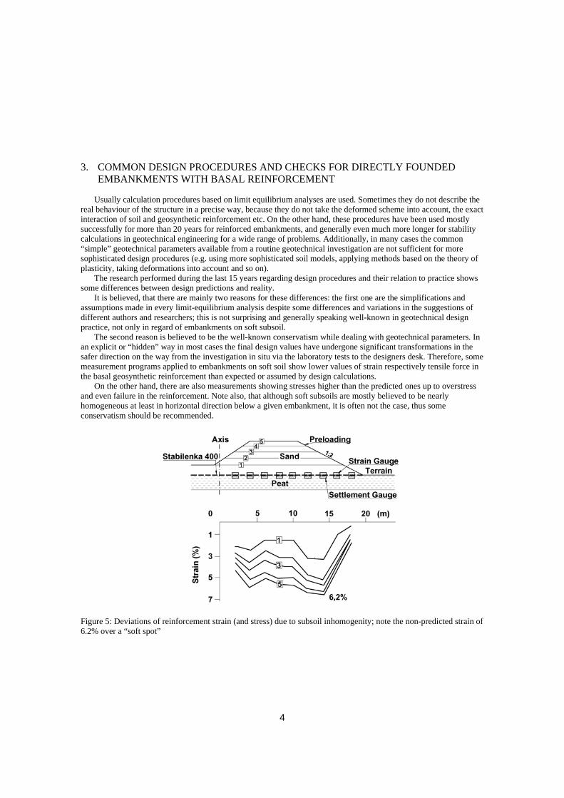
On the other hand, there are also measurements showing stresses higher than the predicted ones up to overstress and even failure in the reinforcement. Note also, that although soft subsoils are mostly believed to be nearly homogeneous at least in horizontal direction below a given embankment, it is often not the case, thus some conservatism should be recommended.
Figure 5: Deviations of reinforcement strain (and stress) due to subsoil inhomogenity; note the non-predicted strain of 6.2% over a “soft spot”
4

In Figure 5 the consequences of such a soft soil inhomogenity are shown. The strain of 6.2% over a “soft spot” far away from the centreline exceeds the design value (project Grossenmeer, Germany).
Figure 6 shows a failure of a sand embankment on soft soil. In that case the required design force in the basal reinforcement had been underestimated based on the overestimation of soft soil strength and also on the underestimation of the negative effects of creep in the reinforcement used. The failure of reinforcement took place with some delay due to creep and resulted in a total failure of the embankment.
Figure 6: Embankment failure on a deep-seated circular surface after failure of basal reinforcement Most of the limit equilibrium analyses are based on the well known procedures of Bishop (circular modes of
failure) and Janbu (polygonal modes of failure) taking additionally into account the retaining stabilizing force from the basal geosynthetic reinforcement as a new component in these classic methods.
In the authors opinion limit equilibrium calculations based on the methods of Bishop and Janbu (although the latter is to some extent conservative) are in the most common cases of embankments on soft soil an appropriate design tool:
- They allow to performing both local and global stability analyses. - They use common, well-known, established geotechnical parameters in the sense of Mohr-Coulomb (soil
unit weights γ and γ’, effective shear strengths parameters ϕ’ and c’, pore over-pressures u, undrained unconsolidated shear strength su (cu) etc.). The test procedures for the estimation of these parameters in situ and in laboratory are well-known; everybody is familiar with them and has got some “geotechnical engineering feeling”, thus big mistakes and/or misunderstandings can be avoided. A more detailed geotechnical investigation can be performed both along and across the future embankment due to the relatively low costs. In the authors opinion it is better to have a large number of simple (cheaper) tests and results over the area in question and in depth than a smaller number of sophisticated ones.
- Most of the embankment failures known are very close to the circular failure mode (see e.g. Fig. 6). - Appropriate software is usually available in the market according to Bishop’s and Janbu’s methods
working mostly very quickly, therefore allowing for a check of many different best case and worst case scenarios (in regard of soil parameters, actual ground water level, construction stages and so on) at acceptable costs.
- The conservatism of results registered for some projects worldwide is in the author’s opinion mostly not due to the procedures themselves, but due to the conservatism in (soft soil) parameters.
5
- From the practical point of view some conservatism is nevertheless useful for all parts participating in the project (owner, investor, consultant, contractor etc.) because the scatter of geotechnical parameters of soft subsoil horizontally and vertically can be remarkable especially for larger embankments. Soft spots cannot always be identified during investigation; the consolidation time (say rate of increase of soft soil strength parallel to embankment’s construction) cannot be predicted exactly. The costs for a stronger (“conservative”) geosynthetic reinforcement are low in relation to the costs of the entire structure and negligible in relation to possible costs for prolonged consolidation “waiting” times, rehabilitation or rebuilding in the case of failure (keep Figure 6 in mind) or insufficient serviceability.
Typical failure modi to be checked in a limit equilibrium analyses are:
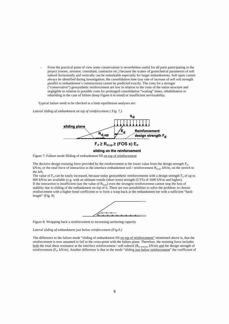
Lateral sliding of embankment on top of reinforcement ( Fig. 7.)
Figure 7: Failure mode Sliding of embankment fill on top of reinforcement The decisive design resisting force provided by the reinforcement is the lower value from the design strength Fd, kN/m, or the total force of interaction in the interface embankment soil / reinforcement Rd,up, kN/m, on the stretch to the left. The value of Fd can be easily increased, because today geosynthetic reinforcements with a design strength Fd of up to 800 kN/m are available (e.g. with an ultimate tensile (short term) strength (UTS) of 1600 kN/m and higher). If the interaction is insufficient (say the value of Rd,up) even the strongest reinforcement cannot stop the loss of stability due to sliding of the embankment on top of it. There are two possibilities to solve the problem: to choose reinforcement with a higher bond coefficient or to form a warp-back at the embankment toe with a sufficient “back-length” (Fig. 8)
Figure 8: Wrapping back a reinforcement to increasing anchoring capacity Lateral sliding of embankment just below reinforcement (Fig.9.) The difference to the failure mode “sliding of embankment fill on top of reinforcement” mentioned above is, that the reinforcement is now assumed to fail in the cross-point with the failure plane. Therefore, the resisting force includes both the total shear resistance at the interface reinforcement / soft subsoil (Rd, bottom, kN/m) and the design strength of reinforcement (Fd, kN/m). Another difference is that in the mode “sliding just below reinforcement” the coefficient of
6
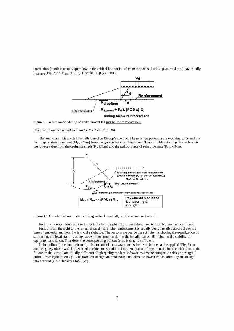
interaction (bond) is usually quite low in the critical bottom interface to the soft soil (clay, peat, mud etc.), say usually Rd, bottom (Fig. 8) << Rd,up (Fig. 7). One should pay attention!
Figure 9: Failure mode Sliding of embankment fill just below reinforcement Circular failure of embankment and soft subsoil (Fig. 10)
The analysis in this mode is usually based on Bishop’s method. The new component is the retaining force and the resulting retaining moment (Mfd, kN/m) from the geosynthetic reinforcement. The available retaining tensile force is the lowest value from the design strength (Fd, kN/m) and the pullout force of reinforcement (FAd, kN/m).
Figure 10: Circular failure mode including embankment fill, reinforcement and subsoil
Pullout can occur from right to left or from left to right. Thus, two values have to be calculated and compared. Pullout from the right to the left is relatively rare. The reinforcement is usually being installed across the entire
base of embankment from the left to the right toe. The reasons are beside the sufficient anchoring the equalization of settlement, the local stability at any stage of construction during the installation of fill including the stability of equipment and so on. Therefore, the corresponding pullout force is usually sufficient.
If the pullout force from left to right is not sufficient, a wrap-back scheme at the toe can be applied (Fig. 8), or another geosynthetic with higher bond coefficients should be foreseen. (Do not forget that the bond coefficients to the fill and to the subsoil are usually different). High-quality modern software makes the comparison design strength / pullout from right to left / pullout from left to right automatically and takes the lowest value conrolling the design into account (e.g. “Huesker Stability”).
7

Squeezing out of soft subsoil below embankment (Fig. 11)
Figure 11: Failure mode Squeezing out of soft subsoil below embankment Soft saturated subsoil is usually of very high plasticity and soft consistency demonstrating a typical plastic behaviour. The lateral outward soil movement mainly in the zones below slopes and near (also outside) the toes is significant: the soft soil tends to squeeze out similar to toothpaste from a tube. The common procedure for a limit equilibrium analysis is shown in Fig. 10. Ea,d, kN/m, is the outward earth pressure in the soft soil, and Ep,d the passive earth pressure. FR,d is the resisting shear force at the bottom of the reinforcement (pay attention on the coefficient of interaction!), and Fc, d is the resisting shear force in the soft soil for the block checked. Fd is the design strength of reinforcement and FA,d the pullout force. Series of failure blocks have to be checked to find out the critical lowest factor of safety. A possible alternative solution to this procedure is to perform an analysis using the polygonal failure plane method of Janbu, which is well known and mostly available in modern software e.g. “Huesker Stability”). 4. ABOUT DEFORMATIONS, SERVICEABILITY AND STRAINS Note, that the basal reinforcement cannot reduce the final total settlement of embankment significantly. What it can definitely do is to guarantee the global and local stability (appropriate design and materials assumed). It can also help to equalize and smooth the settlement differences. In some cases high-strength high-tensile stiffness reinforcement can neutralize a part of the “squeezing out” plastic strains and consequently reduce the settlement to some extent.
Settlement and consolidation analyses are performed using the well-known procedures of soil mechanics neglecting the basal reinforcement, which is (at least for very soft soils of high plasticity) a conservative approach.
We face in the case of embankment on soft soil the well-known handicap while using analytical procedures in geotechnical engineering: the stability calculations (ultimate limit state (ULS)) are not directly coupled to the calculations of deformations (serviceability limit state (SLS)). In our case the gap is even larger due to the generally higher deformability of the system. Remember, that in an ULS limit equilibrium analysis all components of the system are formally considered to be infinitely stiff (e.g. the slices in Bishop’s method), neither elastic nor elastic-plastic and so on. Consequently, a priori no coupled deformation analysis is possible.
Nevertheless, regarding SLS-analysis some help is provided based on the experience available until now: although in analytical procedures regarding settlements and lateral deformations the influence of reinforcement cannot be directly considered, there are some rules based on research and experience. Such a typical rule is e.g. that under the design tensile force the corresponding total strain in the reinforcement should be in the range of 3% to 6%. The total strain comprises the short-term strain and the creep strain. Additionally, it is recommended to limit the creep strain to max 1% and even to 0.5% for sensitive embankments to guarantee the long-term serviceability and to neutralize possible secondary creep in soft soil. Both criteria serve to avoid excessive deformations (especially the
8

lateral ones). On the other hand, a too high tensile stiffness of reinforcement resulting in a strain of e.g. less than 3% can be disadvantageous. At very low strains the full shear resistance of the typically non-cohesive embankment fill cannot develop. The typical strains in a compacted non-cohesive soil for a maximal mobilization of internal shear resistance are 3% to 5%. For larger strains the “post-peak ϕ” should be considered, for lower values – the “pre-peak ϕ”, which could be quite small (Fig. 12.).
Figure 12: Development of shear resistance versus strain in a compacted non-cohesive soil 5. NUMERICAL ANALYSES PROCEDURES
The main advantage of numerical analyses is that they comprise the entire system and not only a series of different typical failure modes like in the case of limit equilibrium analyses, and that the ultimate limit state and serviceability limit state analyses are coupled. The result of a calculation provides information regarding both the stability and the deformations of the system. Because the entire system embankment / reinforcement / soft soil is being analysed as a whole, problematic most probable failure zones and critical failure modes controlling the design can easily be identified at once (failure of slopes, squeezing out of soft soil, combined failure on a deep-seated plane).
Note, that usually numerical analyses (at least using the common software available in the market) tend to underestimate the strain and tensile forces in the geosynthetic reinforcement. Such analyses can be non-conservative regarding the reinforcement.
Some disadvantages of numerical methods are: significant time consumption; significant numerical and geotechnical experience of the design engineer is needed for a correct design; the results are hardly to be checked using other simplified methods; the output is very sensitive to the input parameters and to the soil models (constitutive rules) applied, especially for the soft soil.
Figures 13 and 14 show a typical example of a FEM-analysis. Fig. 13 shows in the upper part a non-reinforced embankment put only on a separating non-woven with low tensile stiffness and strength. The embankment shown in the bottom part is reinforced with a high-strength, high-tensile stiffness woven geosynthetic (Stabilenka®). The non-reinforced system fails before reaching the design height experiencing an extreme settlement. The reinforced one remains stable after installation of the foreseen 6 m of embankment soil, although the settlement is large. (The next steps in design – not shown – are to add additional embankment fill to compensate the settlement). Figure 14 shows analogically the two cases with the corresponding plastic zones (deformation in the non-reinforced failed case not shown). The figures are mentioned as a typical illustration and do not represent a complete design.
9
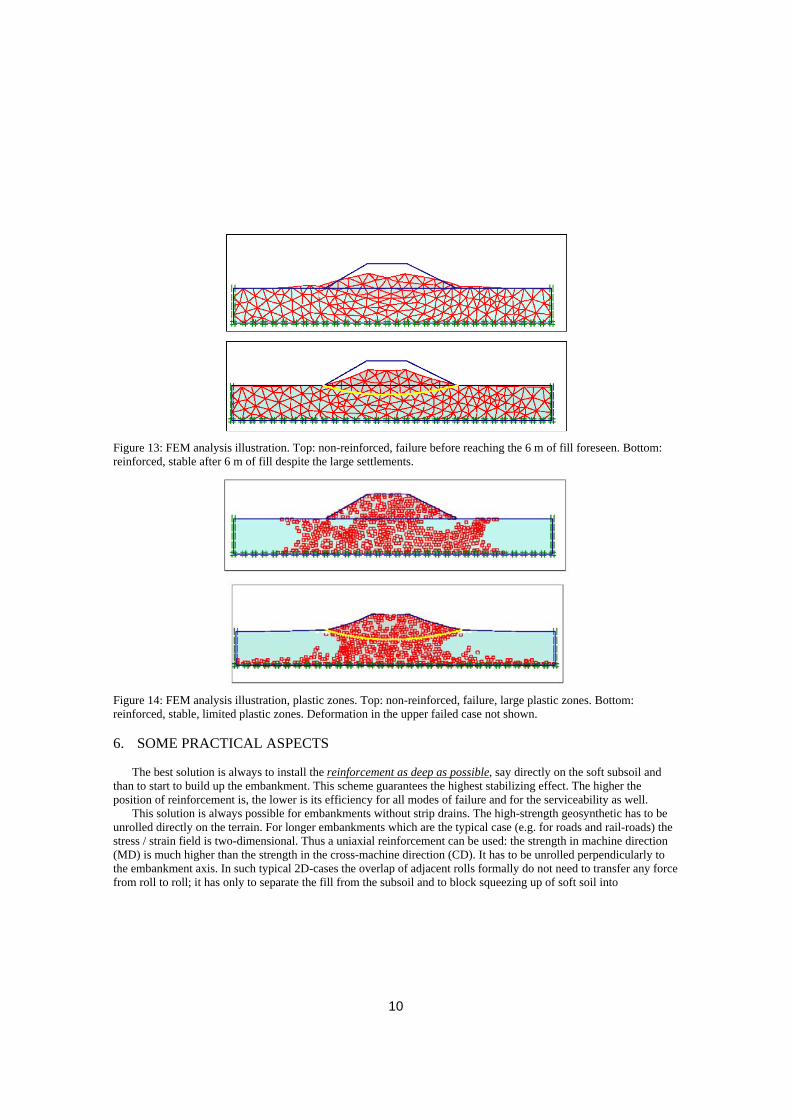
Figure 13: FEM analysis illustration. Top: non-reinforced, failure before reaching the 6 m of fill foreseen. Bottom: reinforced, stable after 6 m of fill despite the large settlements.
Figure 14: FEM analysis illustration, plastic zones. Top: non-reinforced, failure, large plastic zones. Bottom: reinforced, stable, limited plastic zones. Deformation in the upper failed case not shown. 6. SOME PRACTICAL ASPECTS
The best solution is always to install the reinforcement as deep as possible, say directly on the soft subsoil and than to start to build up the embankment. This scheme guarantees the highest stabilizing effect. The higher the position of reinforcement is, the lower is its efficiency for all modes of failure and for the serviceability as well.
This solution is always possible for embankments without strip drains. The high-strength geosynthetic has to be unrolled directly on the terrain. For longer embankments which are the typical case (e.g. for roads and rail-roads) the stress / strain field is two-dimensional. Thus a uniaxial reinforcement can be used: the strength in machine direction (MD) is much higher than the strength in the cross-machine direction (CD). It has to be unrolled perpendicularly to the embankment axis. In such typical 2D-cases the overlap of adjacent rolls formally do not need to transfer any force from roll to roll; it has only to separate the fill from the subsoil and to block squeezing up of soft soil into
10
embankment. Thus, 0.3 m of overlap are recommended, up to 0.5 m in extreme cases (embankment on mud or sludge). Another option (costs time!) is to sew the rolls together.
The main bearing direction of reinforcement is its MD (roll) direction, which is herein oriented across the embankment. Consequently, it is strongly recommended to avoid any overlaps or joints in this direction, although such a solution is theoretically possible: the risk is too high. An insufficient bearing (transfer) capacity of such an overlap or joint can result in a failure of embankment irrespective of the strength of reinforcement installed.
If strip drains have to be installed, one needs a working platform for the equipment (rigs). This situation has to be considered in the design especially in the case of heavy equipment with high masts.
There are mainly two options in such a case. The most common option is to install a first lighter reinforcement only for the working platform, and after the strip drain installation to install on top of the platform the strong reinforcement for the entire embankment. The second option is to install the “final” strong reinforcement from the same beginning below the working platform. In that case, the partial damage due to punching by the rigs has to be considered in the estimation of design strength of reinforcement. Additionally, for such cases an optimised reinforcement can be produced and applied, which is a very interesting patented solution.
For 3D-cases the best solution is to use one layer of biaxial reinforcement, which can be customized. Due to the limited place further details and experience cannot be discussed herein.
Another important issue is the number of reinforcement layers. In earlier stages of geosynthetic applications the allowed design strength of reinforcement has been relatively low, thus two or even three layers of reinforcement have been used with a fill interlayer between them. The situation today is completely different, because very strong reinforcements are available. Therefore, one single strong layer can always be applied instead of e.g. two weaker ones. This single layer solution should be definitely preferred because it is actually the optimal solution as explained below:
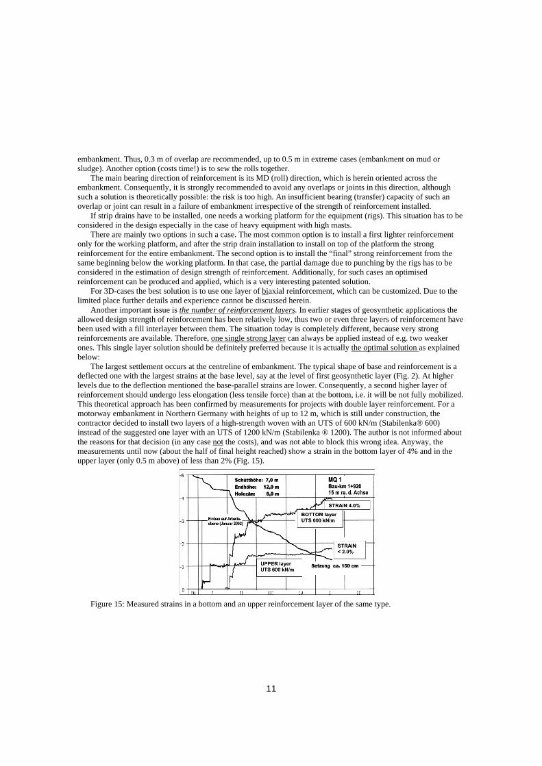
The largest settlement occurs at the centreline of embankment. The typical shape of base and reinforcement is a deflected one with the largest strains at the base level, say at the level of first geosynthetic layer (Fig. 2). At higher levels due to the deflection mentioned the base-parallel strains are lower. Consequently, a second higher layer of reinforcement should undergo less elongation (less tensile force) than at the bottom, i.e. it will be not fully mobilized. This theoretical approach has been confirmed by measurements for projects with double layer reinforcement. For a motorway embankment in Northern Germany with heights of up to 12 m, which is still under construction, the contractor decided to install two layers of a high-strength woven with an UTS of 600 kN/m (Stabilenka® 600) instead of the suggested one layer with an UTS of 1200 kN/m (Stabilenka ® 1200). The author is not informed about the reasons for that decision (in any case not the costs), and was not able to block this wrong idea. Anyway, the measurements until now (about the half of final height reached) show a strain in the bottom layer of 4% and in the upper layer (only 0.5 m above) of less than 2% (Fig. 15).
Figure 15: Measured strains in a bottom and an upper reinforcement layer of the same type.
11

As to be expected the upper layer is significantly less stressed (mobilized), say not used in an efficient way. The bottom layer experiences a strain in the common range, but note, that the final design height is not reached yet. In the author’s opinion, there is a risk of unacceptable overstressing of the bottom layer under the full-height of embankment, while the upper layer is supposed to remain not fully used. In a worst case the contractor will be forced by the supervisor to slow down the construction process and to wait for a sufficient increase of strength in the soft soil, thus facing the risk of not meeting the deadline and paying penalties. Note the significant disadvantageous relation in strain (say tensile force) of 1:2 even for the small vertical distance of 0.5 m between the layers. Summarizing: not only from the point of view of engineering efficiency the best solution is to use one single layer, but also from the point of view of financial efficiency: the owner pays for a second “not fully used” layer, the designer and contractor run the risk of overstressing of the bottom layer.
Some words to the earthwork: Note, that the total amount of the embankment fill to be installed in order to reach the final effective height of embankment above the terrain is much higher than resulting from the formal contour of embankment on the design sheets due to large settlements and horizontal spreading. The “loss of fill” due to spreading can be reduced using a reinforcement of high-tensile stiffness and low creep as mentioned earlier. The tendency can be identified on the FEM-plots (Fig. 13 and 14). There is a simple rule of thumb regarding the real amount of embankment fill to be installed including the soil for overloading in order to accelerate consolidation (to be removed after end of consolidation) and the soil to compensate the settlement, which was confirmed at least for many projects in Germany: the total height (in fact “thickness”) of fill installed is 30% to 50% higher than the sum of the final effective height above the terrain as planned and the settlement to be expected.
A further specific issue is how to choose the stages and time intervals for building up the embankment. The analysis is difficult regardless of the design method: analytical or numerical. The theory is clear in both cases, but the practice can be quite different making precise predictions very difficult. There are irregularities in the parameters of the soft soil both in vertical and horizontal directions, consolidation calculations are very sensitive to the input (e.g. of the coefficient of permeability), the latter can be different in horizontal and vertical direction. The same is valid for the modulus of deformation or the coefficient of compression; in the case of strip drains unpredictable, smearing effects can take place reducing the rate of consolidation etc. 7. SOME PRACTICAL RECOMMENDATIONS:
In the authors opinion and to his knowledge and experience some caution and conservatism are always useful:
- Install one to maximum two meters of embankment fill for every stage of construction. - Do never assume, that the consolidation and increase of strength of soft subsoil has reached the theoretical
values under the stage “i” before starting the stage “i+1”: assume lower, conservative values when performing the stability analysis for that stage “i+1”. This results in higher required strength of reinforcement, but covers the risk of failure with really expansive consequences and possible penalties due to the final deadline of the project.
- Do not believe, that the most critical moment is the time just after installation of the next 1 to 2 m of embankment fill or even the next one to two days: the assumed positive effect of consolidation and subsoil strengthening can take place more slowly than the decrease of available strength in reinforcement due to creep under the increased tensile force. The most critical period can be even some weeks later: this was the case e.g. with the project in Figure 6.
- In any case, use low-creep reinforcement. - Do not believe that the reinforcement could be not required after end of construction or after 2 or 3 years
because of final consolidation, and that durability is may be of less importance: excavations and research at the Rübke test embankment in Germany showed that the high-strength reinforcement (Stabilenka® 200) was still working being under significant tension 14 years after end of construction as can be seen in Figure 16. The results by direct strain-gauges measurements for more than 12 years for other projects (e.g.
12

the Grosssenmeer project in Germany) are similar.
Figure 16: Basal reinforcement tensioned like a string 14 years after end of construction (Rübke test embankment, Germany, StabilenkaR 200). - Pay attention on the appropriate qualified installation and compaction of embankment soil. - Always control the parameters of embankment fill delivered to the site, and compare them to the fill
parameters specified and assumed in design. - Do the same with the geosynthetic reinforcement, which is a key bearing element in the system. Ask in the
stage of design for complete data including short- and long-term strength and strain parameters, design factors etc. (see below) and ask for complete documentation for the product delivered to the building site. Perform input control (at least regarding producer, product etc.) testing at least the short-term stress-strain behaviour and strength using the common international standards and a competent testing laboratory with an appropriate equipment. The experience shows, that it is an advantage to use certified reinforcements with a long-term experience and applications in the background.
8. GEOSYNTHETIC REINFORCEMENT The basal geosynthetic reinforcement is as mentioned above a key bearing element. At the same time there is unfortunately a wide field for speculations and often for mistakes. In the meantime due to intensive research and development a wide range of reinforcing geosynthetics is available. The ultimate tensile strength (UTS) goes up to 1600 kN/m, the ultimate strain varies between 3% and 10% for the materials in question. Different polymers are used as row materials. Wovens, geogrids and geocomposites are available. The geotechnical engineer’s ideal geosynthetic reinforcement would possess the following features:
1. The tensile modulus say tensile stiffness is high in the short- and long-term (guarantees soil-compatible strain values and early mobilisation of tensile force).
2. The propensity to creep is very low (high long-term strength and minimum creep strain). 3. High bond coefficient with the soil in both shear- and pull-out modes (short anchorage lengths, good
interaction between reinforcement and soil). 4. Very high permeability (lowest hydraulic resistance and as a result, no increasing water pressure problems).
13

5. Low damage during installation and soil compaction. 6. High chemical and biological resistance in all conceivable environments. 7. Low costs.
Unfortunately, the ideal reinforcement does not exist yet. Nevertheless, geotechnical engineers have today the
fortunate possibility to choose an appropriate reinforcement always and for any case due to the wide range of materials available: wovens, geocomposites and geogrids made of different polymers.
Today it is not only possible to find a solution in any case, but also to search for the optimal one varying e.g. the polymeric raw material. In Figure 17 the importance and influence of the polymer used are illustrated. The short-term curves of strain versus tensile force are depicted for four typical families of geogrids as an illustration. The graphs are normalized, i.e. the tensile force behind the 100% stress ratio can be 100 or 1000 kN/m. Due to the different polymers used the stress-strain behaviour of the geosynthetics is also very different, e.g. the ultimate strain at failure varies from 12% to 3 %.
Figure 17: Illustration of the influence of polymer used on the stress-strain behaviour of four geosynthetic reinforcement families
The design strength of geosynthetic reinforcement is the most important issue beside the stress-strain behaviour.
It is very different from the ultimate tensile strength (UTS), which is the short-term strength obtained from a wide-strip test in the testing machine for about one minute. Although it is believed to be a well-known fact, there are still designs and specifications available dealing with and defining only the UTS. The consequences can be very problematic including failure of reinforcement and consequently of the embankment. The reduction in strength from UTS down to the really available strength in the structure occurs mainly to following reasons:
Creep, installation and compaction damage, environmental influences and joints or seems (if available in the bearing direction).
14

All these factors are varying for the different geosynthetic reinforcements depending on the polymer used, on the type of product, on the fill material used, on the contacting soils and fluids etc. Consequently, for the same UTS the difference in the final available (design) strength can amount up to two times.
The transition from UTS to the design strength Fd takes place according to the following basic equation:
Fd = UTS / (RFcreep x RFinstdem x RFenv x RFjoint x “X”) Fd - kN/m design strength UTS - kN/m ultimate tensile strength RFcreep - reduction factor for creep RFinstdem - reduction factor for installation and compaction damage RFenv - reduction factor for environmental effects RFjoint - reduction factor for seams and joints “X” additional partial factor of safety for the reinforcement The symbols for the factors above can be different in different countries and standards, but the concept and the
sense is the same worldwide. Note the difference between the reduction factors RF and the additional factor of safety X. The RF’s reflect the
consequences of real mechanical, chemical and physical processes; they are not factors of safety. The additional factor of safety X is another issue. It depends on the safety philosophy in a country or in a standard, on the long-term experience with a given product or on the experience, quality control and quality assurance of the producer of the geosynthetic. The RF’s are obtained by specific testing procedures, are strongly depending on the product and have to be precisely cited and guaranteed by the producer. They have to be known already in the stage of design, because the F d and not the UTS is used in stability calculations.
One more important issue is the coefficient of interaction between reinforcement and soil, which is also a factor in the design calculation (pull-out, sliding) as shown above. It is defined as the ratio of the shear resistance in the interface geosynthetic / soil vs. the inner shear resistance of the soil. The higher the coefficient of interaction is, the shorter the anchorage length and the higher the stability against sliding or squeezing out (see e.g. Fig’s. 7, 9 & 11). Often the coefficient of interaction is different for the pull-out and shear mode: different tests have to be performed.
And last but not least: complete information has to be available about the short- and long-term stress-strain behaviour of the reinforcement.
As recommended above, the design total strain should not exceed 5% to 6%, and the creep strain should be less than 1% or even 0.5% for the tensile force assumed or predicted in analytical design procedures.
This information is also definitely required to perform numerical analyses, because the short- and long-term tensile stiffness (modulus) of reinforcement and not its strength is one of the input values in such calculations.
All the stress-strain information needed can be obtained from the so called isochrones of the reinforcement. They are graphs displaying the relation tensile force / strain / time. Typical isochrones are shown in Fig. 18. From them the design engineer can read out the short-term, the creep and the total strain for a given stress ratio (Fig. 18). The stress ratio is the relation of the effective tensile force to the UTS: the isochrones are so called normalized graphs.
In the example the strains at a stress ratio of 50 % for two different reinforcements are marked: the total, the short-term and the creep strains. For the case to the left they amount to 8.5, 7.0 and 1.5 %, respectively. For the reinforcement to the right the corresponding values are 6.0, 5.0 and 1.0 %. The reinforcement to the right meets for a stress ratio of 50 % the strain recommendations for less sensitive embankments. For that one to the left they can be met only reducing the stress ratio. This means finally to increase the required UTS (say the costs) of the material.
Generally, if the requirements concerning the total strain or the creep strain are not met for a given project and for a given stress ratio, two options are available. One can reduce the stress ratio thus reducing all types of strain (Fig. 18) but paying consequently for more geosynthetic material. The second option is to choose another reinforcement with a higher short- and long-term tensile stiffness, say with steeper isochrones. The latter is the more efficient way.
15
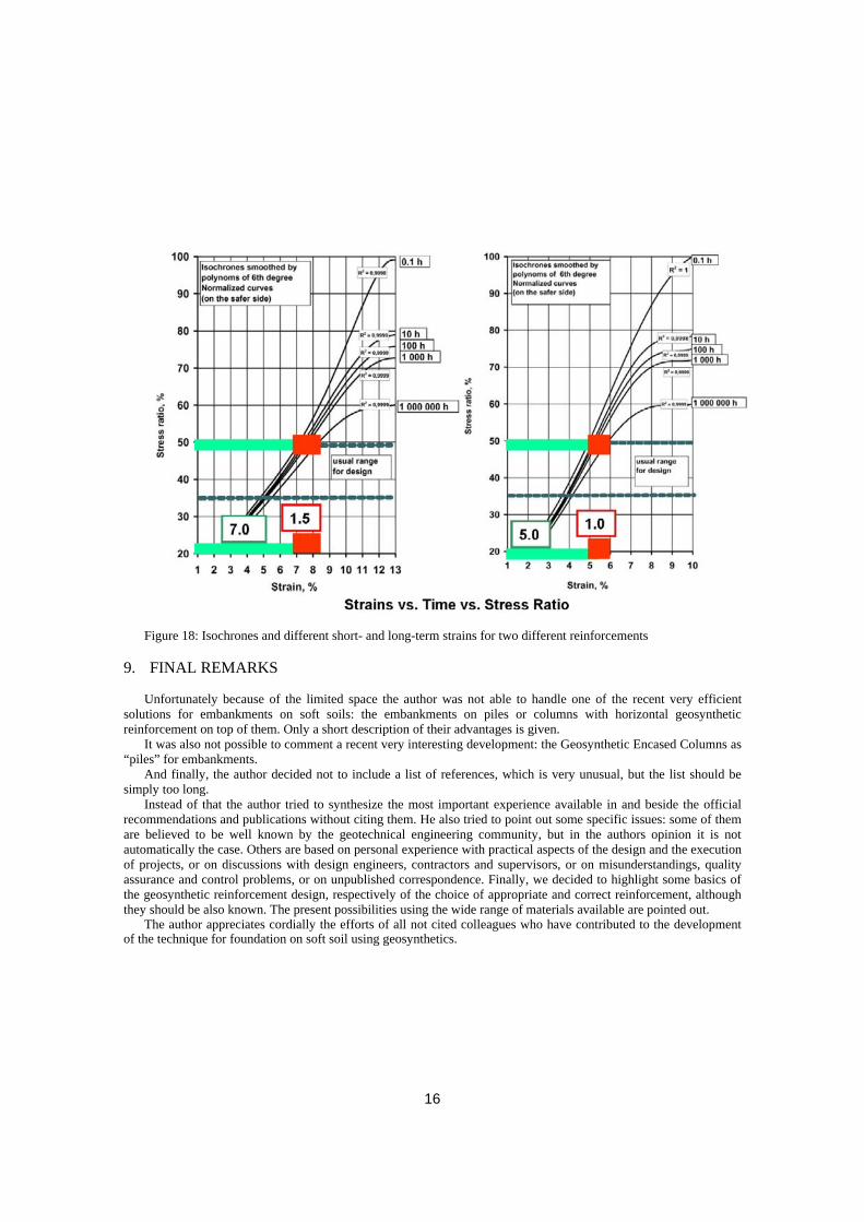
Figure 18: Isochrones and different short- and long-term strains for two different reinforcements
9. FINAL REMARKS
Unfortunately because of the limited space the author was not able to handle one of the recent very efficient solutions for embankments on soft soils: the embankments on piles or columns with horizontal geosynthetic reinforcement on top of them. Only a short description of their advantages is given.
It was also not possible to comment a recent very interesting development: the Geosynthetic Encased Columns as “piles” for embankments.
And finally, the author decided not to include a list of references, which is very unusual, but the list should be simply too long.
Instead of that the author tried to synthesize the most important experience available in and beside the official recommendations and publications without citing them. He also tried to point out some specific issues: some of them are believed to be well known by the geotechnical engineering community, but in the authors opinion it is not automatically the case. Others are based on personal experience with practical aspects of the design and the execution of projects, or on discussions with design engineers, contractors and supervisors, or on misunderstandings, quality assurance and control problems, or on unpublished correspondence. Finally, we decided to highlight some basics of the geosynthetic reinforcement design, respectively of the choice of appropriate and correct reinforcement, although they should be also known. The present possibilities using the wide range of materials available are pointed out.
The author appreciates cordially the efforts of all not cited colleagues who have contributed to the development of the technique for foundation on soft soil using geosynthetics.
16