embedded amit aneja scalable platforms based on 2nd ... · 326336 embedded scalable platforms based...
TRANSCRIPT

326336
Embedded
Scalable Platforms
based on 2nd
Generation Intel®
Core™
microarchitecture
System Bring-up
Guide
October, 2011
Application Note
Amit Aneja
Platform Architect
Rahul Anila Ramachandran
Graduate Intern Technical
Intel Corporation

2
Executive Summary
Embedded Scalable platforms include embedded desktop and embedded
workstation class platforms.
Putting together all the software and hardware ingredients of an Intel®
Architecture-based embedded scalable platform may not be an obvious
and trivial task. This can be particularly true if you are new to this class
and generation of Intel Architecture platforms, and trying to evaluate the
capability and features of processor, chipset and other system
components. Also, it is quite possible if the system is not assembled
properly with the required hardware, firmware and other software
components, it may not function initially. Therefore it is recommended to
carefully follow the system bring-up procedure.
This application note serves as a reference guide for bringing up the
hardware and integrating the software components to boot-up the
embedded scalable system to an operating system.
This application note serves as a reference guide for bringing up the
hardware and integrating the software components to boot-up the
embedded scalable system to an operating system. An Intel Customer
Reference platform based on the 2nd generation Intel® Core™ processor
family is used for the purpose of demonstration. This ATX form factor
reference board has most features that are available in common-off-the-
shelf (COTS) embedded boards in different embedded form factors (ATX,
Embedded Scalable Platforms based on 2nd Generation Intel® Core™ microarchitecture: Board Bring-up Guide
3
Micro-ATX, Mini-ITX, etc). Also, the guide provides a step-by-step
procedure to set up and assemble the hardware for the platform, make
firmware updates, and to load a working operating system (Linux*),
along with the necessary driver support including the LAN Driver and
graphics drivers for the corresponding platforms.
The Intel® Embedded Design Center provides qualified developers with
web-based access to technical resources. Access Intel Confidential design
materials, step-by step guidance, application reference solutions, training,
Intel’s tool loaner program, and connect with an e-help desk and the
embedded community. Design Fast. Design Smart. Get started today.
www.intel.com/embedded/edc.

Embedded Scalable Platforms based on 2nd Generation Intel® Core™ microarchitecture: Board Bring-up Guide
4
Contents
Business Challenge ................................................................................................. 5
Introduction ........................................................................................................... 5
2nd Generation Intel® Core™ processor and Intel® Pentium® Processors with Intel® Q67/B65/H61 Express Chipsets (Formerly Sugar Bay Platform) .... 5
Intel® Xeon®, 2nd Generation Intel® Core™ and Intel® Pentium® Processors with Intel® C206 Chipset (Formerly Bromolow Platform) ........ 6
Pre Hardware Setup ................................................................................................ 8
Required Hardware Components ............................................................. 9
Assembly of Hardware Components ......................................................................... 10
Jumper Settings .................................................................................. 20
Clear RTC Jumper settings.................................................................... 21
Clear CMOS Jumper settings ................................................................. 22
BIOS Configuration Jumper settings ....................................................... 23
TPM (Trusted Platform Module) Functionality Jumper settings .................... 24
Installing Software Components .............................................................................. 24
Installing Open Source Operating System – Fedora 15* ............................ 28
Firmware Update Procedure ................................................................................... 49
Installing Device Drivers ........................................................................................ 50
Conclusion ........................................................................................................... 50
References ........................................................................................................... 51

Embedded Scalable Platforms based on 2nd Generation Intel® Core™ microarchitecture: Board Bring-up Guide
5
Business Challenge
Embedded Scalable platforms find usage in various embedded applications including retail point-of-sale terminals, digital signage, digital security surveillance, medical, gaming, communications and industrial automation and control. These varied application requirements use embedded desktop and workstation class platforms available in different embedded board form factors like micro-ATX, mini-ITX, PICMG1.3, and others. For hardware designers and software developers new to these platforms, the process of integrating all the hardware and software components can be quite involved and sometimes require referring many documents to be up and running in order to evaluate and test the system. To make this process simpler, we documented all the steps in one single document that can then be used as a reference guide to get started.
Introduction
The Intel reference platform is used in this application note for the purpose of demonstrating the key hardware and software components and is a representative of the following two types of embedded scalable platforms:
2nd Generation Intel® Core™ processor and Intel® Pentium® Processors with Intel® Q67/B65/H61 Express Chipsets (Formerly Sugar Bay Platform)
The first platform formerly codenamed Sugar Bay offers a 2nd Generation Intel® Core™ Processor Family (Intel® Core™ i7 processor, Intel® Core™ i5 processor and Intel® Core™ i3 processor) with Intel® 6 Series Express Chipset.

Embedded Scalable Platforms based on 2nd Generation Intel® Core™ microarchitecture: Board Bring-up Guide
6
Figure 1.0 Block diagram of of Sugar Bay platform
Intel® Core™ i7-2600Intel® Core ™ i5-2400Intel® Core ™ i3-2120
Intel® Q67 ChipsetIntel® B65 ChipsetIntel® H61 Chipset
PCI Express* x16 Gen2
Analog VGA
Display PortsHDMI, DVI, DP, SDVO
Intel® High Definition Audio
8 PCI Express X1 Gen2
Intel® GbE LAN PHY
2 SATA @ 6Gb/s, 4 SATA @ 3Gb/s
4 PCI Bus Masters
14 Hi-Speed USB 2.0 Ports
Dual Channel DDR31066/1333
Processor Graphics
DMI FDI
This platform can be used for evaluation of next generation processor features including Intel® Advanced Vector Extensions (Intel® AVX) along with processor graphics features with Intel® HD Graphics 2000 fully integrated on the same monolithic processor die.
The Intel® 6 series Express Chipsets offer PCIe* gen 2.0 running at up to 5 GT/s, SATA 3.0 with data transfer rates of up to 6 Gb/s, USB 2.0 along with Analog/Digital graphics interfaces and system manageability capabilities with Intel® AMT 7.0 technology (only select processor and chipset SKUs support Intel AMT 7.0).
Also, refer to [6] of the References section for a video enabled presentation that provides a quick overview of this platform.
Intel® Xeon®, 2nd Generation Intel® Core™ and Intel® Pentium® Processors with Intel® C206 Chipset (Formerly Bromolow Platform)

Embedded Scalable Platforms based on 2nd Generation Intel® Core™ microarchitecture: Board Bring-up Guide
7
The second platform formerly codenamed Bromolow includes the Intel® Xeon® Processor E3-1200 Product Family with the Intel® C206 Chipset. This platform incorporates the quad-core Intel Xeon processor E3-1200 product family for compute-intensive needs and the 2nd Generation Intel® Core™ i3-2120 processor for dual-core processing needs along with Intel® C206 chipset.
Figure 2.0 Block diagram of Bromolow platform
Intel® Xeon processor E3-1275,
Intel® Xeon processor E3-1225,Intel® Core i3-2120
Intel® C206 chipset
PCI Express* x20 I/O Gen2
Analog VGA
Display PortsHDMI, DVI, DP, SDVO
Intel® High Definition Audio
8 PCI Express X1 Gen2
Intel® GbE LAN PHY
2 SATA @ 6Gb/s, 4 SATA @ 3Gb/s
4 PCI Bus Masters
14 Hi-Speed USB 2.0 Ports
Dual Channel DDR1066/1333
Processor Graphics
DMI FDI
This platform can be used to evaluate and develop compute intensive applications using the quad-core Intel® Xeon processor E3-1200 product family.
The Intel® Xeon® processor E3-1200 product family offers high end processor graphics, display and media capabilities with Intel® HD Graphics P3000 built-in.
For applications that are I/O intensive, this platform offers PCIe port bifurcation capabilities to support data traffic from multiple I/O devices.
To add to the robustness of the data traffic between the processor and memory subsystem, Error Correction Code (ECC) capability is supported by the integrated memory controller on the processor.

Embedded Scalable Platforms based on 2nd Generation Intel® Core™ microarchitecture: Board Bring-up Guide
8
The Intel C206 chipset offers the same capabilities as the Intel 6 Series Express Chipsets discussed above and drives some of the platform features. For more details, refer to the Intel 6 Series Express Chipsets and Intel® C200 Series Chipsets datasheet (see [12] of the References section).
Also, refer to [7] of the References section for a video enabled presentation that provides a quick overview of this platform.
Boards based on these two embedded scalable platforms are available from various embedded board manufacturers (see [11] of References section for a list of Intel® Embedded Alliance members offering these platform solutions in various embedded board form factors). In this white paper, we use the Intel reference board as an example to show step-by-step how to bring up the system.
Pre Hardware Setup
The Table below lists some of the key features and capabilities of the Intel reference board. The embedded scalable boards available off-the-shelf might have a different feature set and board form factor based on requirements of the embedded applications they are built-for.
Table 1. Key Features of the Intel Reference Board
Board Form factor ATX
PCB dimensions 9.6" x 12.0" x 0.062"
PCB layer count & stack up 4
CPU support 2nd Generation Intel® Core™ processor family and Intel® Xeon® processor E3-1200 family (Socket H2)
SDRAM type support DDR3
SDRAM speed support 1066/1333 Mhz
SDRAM configuration support
2 Channel with 2 UDIMMs per Channel
SDRAM ECC support Yes (ECC memory support is only available on Bromolow platform processor and chipset SKU pairings only)
PCH support Intel® 6 Series Chipset and Intel® C206 Chipset
Digital Display Ports 1 Display Port, 1 HDMI
Analog Display Ports 1 VGA
Audio Support HD Audio support

Embedded Scalable Platforms based on 2nd Generation Intel® Core™ microarchitecture: Board Bring-up Guide
9
USB interface USB 2.0 front and back panel ports
SATA interface 2 SATA3.0 and 4 SATA2.0 ports
LAN Intel® 82579 gigabit Ethernet PHY
Manageability Intel ME7.0 and Intel AMT 7.0
SPI capacity Two 8MB SPI chips for storing Firmware
Clocking Full Clock Integration Mode (FCIM) supported
PCIe interface 1 x16 PCIe Gen2.0 interface from the processor, 2 x1 PCIe Gen2.0 lanes from the chipset
Voltage Regulation VR12 controller
Required Hardware Components
The following hardware components will be required to assemble the system before booting-up.
1. Intel Embedded Scalable platform (Intel Reference board used for demonstration)
2. DDR3 UDIMM memory sticks
3. Heat Sink/Fan Unit
4. Standard ATX 450W (recommended) power supply with 2x12, 2x2 motherboard power supply connectors
5. Analog (VGA) or Digital (HDMI/DVI/DisplayPort) display options
6. Keyboard (USB interface)
7. Mouse (USB interface)
8. Hard Disk Drive for storage (SATA 3.0 or SATA 2.0 interface)
9. CD/DVD disk drive (SATA 3.0 or SATA 2.0 interface)
10. Power Supply Cable for the ATX 450W Power Supply unit
11. SATA disk drive power and data cable
12. Analog or Digital display data and power cables
13. Operating System Installation CD/DVD (Fedora 15 Linux operating system used in this application note)
14. Ethernet Cable (for connecting the system to internet)

Embedded Scalable Platforms based on 2nd Generation Intel® Core™ microarchitecture: Board Bring-up Guide
10
Assembly of Hardware Components
The following procedure provides step-by-step details on how to assemble the various hardware components. Figure 3 shows the unassembled Intel® customer reference platform and notes the various platform interfaces.
Figure 3: Embedded Sugar Bay and Bromolow Customer Reference Platform
2nd Generation Intel®
Core™ Processor
Intel® 6 Series Chipset

Embedded Scalable Platforms based on 2nd Generation Intel® Core™ microarchitecture: Board Bring-up Guide
11
Figure 4: Processor Assembly on the LGA1155 socket
Step 1: Populate the LGA1155 socket with the selected processor for the platform.
Carefully unlock the metal socket assembly and remove the plastic cover from the LGA 1155 socket. Insert the processor in the socket carefully as shown in Figure 4 to avoid any damage to the pins in the socket. Make sure the pin0 alignment is correct while inserting the processor on the socket as shown in Figure 5.

Embedded Scalable Platforms based on 2nd Generation Intel® Core™ microarchitecture: Board Bring-up Guide
12
Figure 5: Processor pin alignment
Figure 6 shows the processor properly seated in the socket. Lock the processor in place with the top metal socket assembly after seating it in the socket.
Figure 6: Intel® Core™ i7-2600 processor seated on LGA 1155 socket

Embedded Scalable Platforms based on 2nd Generation Intel® Core™ microarchitecture: Board Bring-up Guide
13
Step 2: Attach the processor heat sink/fan unit.
Position the heat sink assembly over the processor as shown in Figure 7 making sure all the four fasten tips of the heat sink align with the holes around the processor socket on the board.
a. Make sure fastener is in pre-installation position (Figure 7).
b. Apply thumb pressure to the top of each of the fastener cap (Figure 7) and press the fastener caps in diagonal sequence (press one pair of diagonally opposite ends and then the other). All the four fastener caps should slide down to lock into fastener base (audible “click” upon engagement).
Do a final check to make sure the heat sink is seated properly and locked in place over the processor/socket assembly.
Figure 7: Heat Sink Assembly
In case the heat sink/fan unit mounted on the processor needs to be detached, make sure the fastener caps that are diagonally opposite are turned in the anti-clockwise direction as indicated by the arrow in Figure 8. Repeat the same for the next set of diagonally opposite fastener caps and then carefully lift the fan from the slot.
a. b.

Embedded Scalable Platforms based on 2nd Generation Intel® Core™ microarchitecture: Board Bring-up Guide
14
Figure 8: Unmounting the Heat Sink Assembly
Step 3: Plug the processor heat sink power cable connector into 4-pin socket as shown in Figure 9.

Embedded Scalable Platforms based on 2nd Generation Intel® Core™ microarchitecture: Board Bring-up Guide
15
Figure 9: Heat Sink Power Supply connector
Step 4: Insert the DDR3 DIMM in the Channel A/B (DIMM0/1) sockets.
The board has DIMM1 sockets of both channel A and B colored blue to distinguish them from the DIMM0 socket. Channels must be populated in order starting with DIMM1 socket (farthest from the processor first=blue) on either channel otherwise the board may not boot as shown in Figure 10.

Embedded Scalable Platforms based on 2nd Generation Intel® Core™ microarchitecture: Board Bring-up Guide
16
Figure 10: Memory Channel and DIMM Configuration
Step 5: Attach the Hard Disk Drive and connect the SATA data cable into one of the 6 available SATA ports as shown in Figure 11 and the SATA power cable to the disk drive.

Embedded Scalable Platforms based on 2nd Generation Intel® Core™ microarchitecture: Board Bring-up Guide
17
Figure 11: SATA connector for Disk Drive
Step 6: Plug the USB keyboard and mouse using one of the USB ports (Figure 12) in the back panel.
Figure 12: USB ports on Back Panel
SATA 2.0 Ports
SATA 3.0 Ports

Embedded Scalable Platforms based on 2nd Generation Intel® Core™ microarchitecture: Board Bring-up Guide
18
Step 7: Standard ATX power supply unit of at least 450W output is recommended for this class of Intel® Architecture based platform.
Step 8: Plug the ATX 2x12 power connector for the platform into the socket as shown in Figure 13.

Embedded Scalable Platforms based on 2nd Generation Intel® Core™ microarchitecture: Board Bring-up Guide
19
Figure 13: Power Supply ATX 2x12 connector
Step 9: Plug the ATX 12V 2x2 power connector for the CPU into the socket as shown in Figure 14.
Figure 14: CPU Power Supply connector

Embedded Scalable Platforms based on 2nd Generation Intel® Core™ microarchitecture: Board Bring-up Guide
20
Step 10: Finally, plug the analog (VGA) or digital display graphics connector into one of the back panel display ports (HDMI, DisplayPort and VGA graphics ports available on the reference board).
Step 11: Attach a CD/DVD drive for installing the operating system and other software on the system.
Connect one end of the SATA data cable to the CD/DVD drive and the other end to one of the six SATA ports. Power on the drive using the SATA power cable from the power supply unit.
Figure 15: Attaching CD/DVD drive for installing OS
Jumper Settings
This section covers some of the Jumper settings available on the reference board and their configuration options. Please note some or all of these jumpers may not be available on a COTS platform, refer to the datasheet of the actual embedded scalable board you are evaluating.
Power Supply
CD/DVD Drive
SATA Data cable
SATA power cable
SATA Ports

Embedded Scalable Platforms based on 2nd Generation Intel® Core™ microarchitecture: Board Bring-up Guide
21
Clear RTC Jumper settings
Figure 14: Clear RTC Jumper on the board
a. Jumper setting (1-2) is the normal or default setting
b. Jumper setting (2-3) is for clearing the RTC (Real Time Clock of the system)

Embedded Scalable Platforms based on 2nd Generation Intel® Core™ microarchitecture: Board Bring-up Guide
22
Clear CMOS Jumper settings
Figure 15: Clear CMOS Jumper on the board
a. Jumper setting (1-2) is the normal or default setting
b. Jumper setting (2-3) is for clearing the CMOS memory of the system

Embedded Scalable Platforms based on 2nd Generation Intel® Core™ microarchitecture: Board Bring-up Guide
23
BIOS Configuration Jumper settings
Figure 16: BIOS Config Jumper on the board
a. Jumper setting (1-2) is the normal or default setting
b. Jumper setting (2-3) is for the BIOS Config mode
c. Jumper setting (No JMP) which refers to no jumper on the pins is used for the BIOS Recovery mode

Embedded Scalable Platforms based on 2nd Generation Intel® Core™ microarchitecture: Board Bring-up Guide
24
TPM (Trusted Platform Module) Functionality Jumper
settings
Figure 17: TPM Functionality Jumper on the board
a. Jumper setting (1-2) is the normal or default setting which enables the TPM functionality
b. Jumper setting (2-3) is for disabling the TPM functionality
Some of the jumper configuration settings are also printed on the board in the case of Intel reference board. The board is typically shipped with default jumper settings configured on the board, but a quick check of these settings can be performed using the above information.
As mentioned before, please refer to the board datasheet for the embedded board you are evaluating to check the default jumper settings and configuration options.
Installing Software Components This section walks you through the procedure for powering on the board, configuring the BIOS and installing the desired software (Operating System and Applications) for evaluating the embedded scalable platforms. Assemble the board using the instructions in the Assembly of Hardware Components section before starting with the installation of software components. This

Embedded Scalable Platforms based on 2nd Generation Intel® Core™ microarchitecture: Board Bring-up Guide
25
system bring-up guide uses the installation of Fedora 15 Linux as an example of operating system installation. Other operating systems have different methods of installation.
Step 1: Power and Reset button are provided on the board (Refer to Figure 3). Power on the board using the Power-on button and the following BIOS flash screen will appear.
Figure 18: BIOS flash screen after the board is powered-on
Step 2: Immediately press the <F2> key when this screen flashes to enter into the BIOS Menu, if Boot options need to be modified or for other changes needed in the BIOS settings. The following BIOS menu screen will appear. Please note the following BIOS menu screenshots are for the purpose of reference only, the BIOS settings interface, options and settings can vary based on the BIOS vendor specific implementation.

Embedded Scalable Platforms based on 2nd Generation Intel® Core™ microarchitecture: Board Bring-up Guide
26
Figure 19: BIOS Menu Screen
Step 3: Using the keyboard arrow buttons, select the ’Boot’ tab on the top. After entering the Boot options window configure the boot priorities. For instance, the boot menu option screen will be displayed as shown in Figure 20. If the OS needs to be installed from the CD/DVD onto the hard disk then the CD/DVD drive option in the boot-up menu list is selected by hitting Enter.
Embedded Scalable Platforms based on 2nd Generation Intel® Core™ microarchitecture: Board Bring-up Guide
27
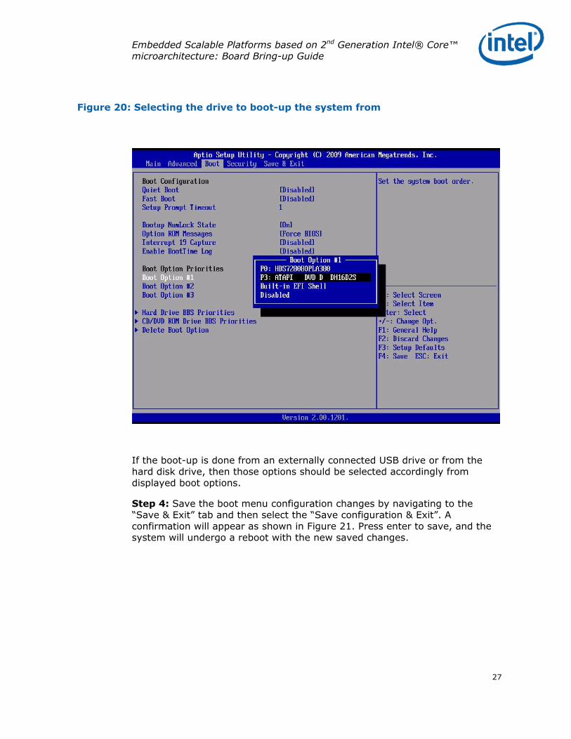
Figure 20: Selecting the drive to boot-up the system from
If the boot-up is done from an externally connected USB drive or from the hard disk drive, then those options should be selected accordingly from displayed boot options.
Step 4: Save the boot menu configuration changes by navigating to the “Save & Exit” tab and then select the “Save configuration & Exit”. A confirmation will appear as shown in Figure 21. Press enter to save, and the system will undergo a reboot with the new saved changes.
Embedded Scalable Platforms based on 2nd Generation Intel® Core™ microarchitecture: Board Bring-up Guide
28
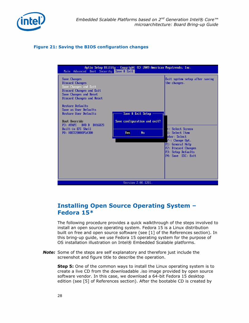
Figure 21: Saving the BIOS configuration changes
Installing Open Source Operating System – Fedora 15*
The following procedure provides a quick walkthrough of the steps involved to install an open source operating system. Fedora 15 is a Linux distribution built on free and open source software (see [1] of the References section). In this bring-up guide, we use Fedora 15 operating system for the purpose of OS installation illustration on Intel® Embedded Scalable platforms.
Note: Some of the steps are self explanatory and therefore just include the screenshot and figure title to describe the operation.
Step 5: One of the common ways to install the Linux operating system is to create a live CD from the downloadable .iso image provided by open source software vendor. In this case, we download a 64-bit Fedora 15 desktop edition (see [5] of References section). After the bootable CD is created by

Embedded Scalable Platforms based on 2nd Generation Intel® Core™ microarchitecture: Board Bring-up Guide
29
burning the downloaded .iso image, set the BIOS boot configuration to boot from the CD. After the system boots into this media, the following screens appears.
Figure 22: Initial boot from Live CD

Embedded Scalable Platforms based on 2nd Generation Intel® Core™ microarchitecture: Board Bring-up Guide
30
Figure 23: System boots from the Live CD to Fedora 15
Step 6: The Fedora 15 Live Desktop screen appears as shown in Figure 24. For evaluating the basic features and capabilities the live CD itself can be used. For installing the operating system on the hard disk drive, just click on Desktop Icon – “Install to Hard Drive” to start the installation process.

Embedded Scalable Platforms based on 2nd Generation Intel® Core™ microarchitecture: Board Bring-up Guide
31
Figure 24: Fedora 15 Live Desktop screen
The Fedora Installer screen will appear, as shown in Figure 25. Select the appropriate keyboard language from the list and click “Next”.

Embedded Scalable Platforms based on 2nd Generation Intel® Core™ microarchitecture: Board Bring-up Guide
32
Figure 25: Select the appropriate keyboard language option

Embedded Scalable Platforms based on 2nd Generation Intel® Core™ microarchitecture: Board Bring-up Guide
33
Step 7: For using a local storage medium like a hard disk drive or a solid state drive select the first option of “basic storage devices” as shown in Figure 26 and click Next.
Figure 26: Select the appropriate storage device for installation

Embedded Scalable Platforms based on 2nd Generation Intel® Core™ microarchitecture: Board Bring-up Guide
34
Step 8: Enter the desired name for the system if the name needs to be set to something other than the default name. The default computer name will be localhost.localdomain as shown in Figure 27.
Figure 27: Setting the Linux system name

Embedded Scalable Platforms based on 2nd Generation Intel® Core™ microarchitecture: Board Bring-up Guide
35
Figure 28: Select the appropriate location and time zone for the system

Embedded Scalable Platforms based on 2nd Generation Intel® Core™ microarchitecture: Board Bring-up Guide
36
Figure 29: Create a password for the Root User/Domain

Embedded Scalable Platforms based on 2nd Generation Intel® Core™ microarchitecture: Board Bring-up Guide
37
Step 9: Next, select the type of installation. Typically for a fresh install select the first option “Use all Space” as shown in Figure 30. This option is to remove all the partitions created earlier by other operating systems installed on the hard disk (if any). After this, select the “Write Changes to Disk” option to begin the installation as shown in Figure 31.
Figure 30: Select the type of installation

Embedded Scalable Platforms based on 2nd Generation Intel® Core™ microarchitecture: Board Bring-up Guide
38
Figure 31: Select the ‘Write Changes to Disk’ option

Embedded Scalable Platforms based on 2nd Generation Intel® Core™ microarchitecture: Board Bring-up Guide
39
Figure 32: OS Installation begins

Embedded Scalable Platforms based on 2nd Generation Intel® Core™ microarchitecture: Board Bring-up Guide
40
Step 10: Upon the successful completion of the installation process, the Congratulations screen appears, as shown in Figure 33. Click “Close”.
The Fedora 15 Operating System has now been successfully installed on the hard drive. Perform a system reboot using the Reset button on the board (refer to Figure 3). After the reboot, enter the BIOS menu by pressing F2 and change the boot option.
Figure 33: Finishing the Installation
Embedded Scalable Platforms based on 2nd Generation Intel® Core™ microarchitecture: Board Bring-up Guide
41
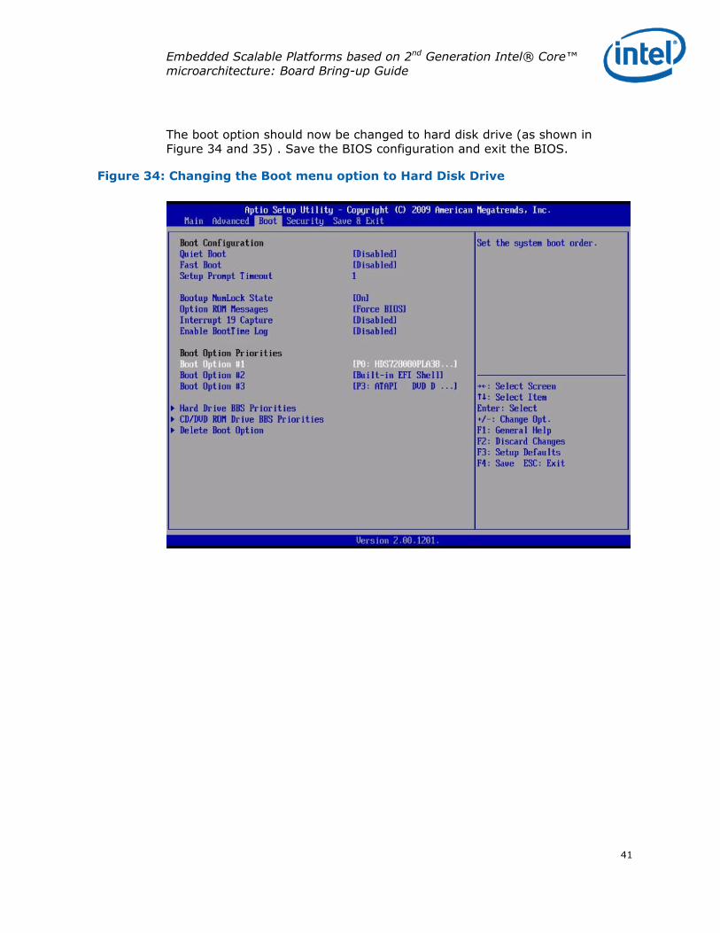
The boot option should now be changed to hard disk drive (as shown in Figure 34 and 35) . Save the BIOS configuration and exit the BIOS.
Figure 34: Changing the Boot menu option to Hard Disk Drive

Embedded Scalable Platforms based on 2nd Generation Intel® Core™ microarchitecture: Board Bring-up Guide
42
Figure 35: Save the new BIOS configuration and Exit

Embedded Scalable Platforms based on 2nd Generation Intel® Core™ microarchitecture: Board Bring-up Guide
43
After saving the BIOS configuration, the Welcome screen will appear as shown in Figure 36. Click on “Forward”.
Figure 36: Fedora 15 Welcome screen after system boots from hard disk drive

Embedded Scalable Platforms based on 2nd Generation Intel® Core™ microarchitecture: Board Bring-up Guide
44
Step 11: Next, accept the licensing agreement by clicking “Forward”. Then create a Linux user profile by providing the appropriate username and password as shown in Figure 37.
Click “Forward” to continue.
Figure 37: Create Linux System User profile

Embedded Scalable Platforms based on 2nd Generation Intel® Core™ microarchitecture: Board Bring-up Guide
45
Figure 38: Set the system Date and Time

Embedded Scalable Platforms based on 2nd Generation Intel® Core™ microarchitecture: Board Bring-up Guide
46
Step 12: The Hardware Profile screen will appear, as shown in Figure 39. Determine if you are going to send the profile or not and make the appropriate selection.
Click Finish.
Figure 39: Send the System Hardware Profile to Fedora Project (Optional)

Embedded Scalable Platforms based on 2nd Generation Intel® Core™ microarchitecture: Board Bring-up Guide
47
The system will boot into the GUI for Fedora 15 as shown in Figure 40.
Figure 40: Fedora 15 Desktop

Embedded Scalable Platforms based on 2nd Generation Intel® Core™ microarchitecture: Board Bring-up Guide
48
Step 13: The CPU model and family details, CPU capabilities like CPU frequency and cache size, and the features can be checked using the command: cat /proc/cpuinfo
Figure 41: Checking processor attributes

Embedded Scalable Platforms based on 2nd Generation Intel® Core™ microarchitecture: Board Bring-up Guide
49
Step 14: Fedora 15 provides a System Monitor GUI to check the system resource usage including CPU and memory utilization to monitor the resource utilization while running the desired application workload.
Figure 42: Checking System resource usage through System Monitor GUI
Firmware Update Procedure
Many times system updates including patches for processor microcode and other issue or bug fixes are released as part of a BIOS binary update which includes a system BIOS component and the Intel® Manageability Engine firmware. Depending upon the board design and the specific board vendor, there could be different options to update the BIOS and also different BIOS binaries (depending upon the BIOS implementation).
Most of the time the BIOS on the SPI interface-based EEPROMs are programmed using software-only methods, wherein the system is booted to

Embedded Scalable Platforms based on 2nd Generation Intel® Core™ microarchitecture: Board Bring-up Guide
50
an operating system (usually Windows* or DOS), and then a BIOS update software utility is used to program the binary. This method is more common on production systems where the EEPROM chips are soldered down. Another way to program the EEPROM memory is to use a SPI EEPROM programmer by physically removing the chips from the board and then programming them. This method is more commonly used when EEPROM chips are not soldered down on the board.
The Intel customer reference board in this case offers a removable EEPROM device, so it can be programmed with either of the two methods described.
The Intel desktop motherboards (see [8] of References section) provide the BIOS binaries in three formats for updating the BIOS, as an example. [9] of References section shows the BIOS update options for the Intel Desktop board DQ67SW. The latest BIOS updates for this board are released on the Intel.com website (see [10] of References section).
For boards from third party vendors, please refer to the board datasheet, user guide and other documents for details on specific BIOS update procedures. Also, it is recommended to carefully follow the guidelines and procedures for BIOS updates for the specific board under evaluation to avoid putting the board in a dysfunctional state.
Installing Device Drivers
After the system boots into the operating system the next critical software component that is needed are the device drivers. A typical platform will require drivers like the LAN driver, Graphics driver, Audio driver, storage driver, etc. Device drivers for Windows operating system can be downloaded from http://downloadcenter.intel.com by selecting the appropriate processor, chipset, motherboard or other system components. As an example, selecting Processor>Desktop> Intel® Core™ i7 Processor, the website provides a list of device drivers relevant for this class of processors. Next, selecting the operating system from the list filters the software components by relevance.
Open source Linux operating system drivers for platforms based on Intel® Architecture are released on http://kernel.org/. Another useful source for open source graphics driver releases is http://intellinuxgraphics.org/.
Conclusion
A Sandy Bridge micro-architecture based embedded scalable platform is a great way to meet the design needs of many compute and graphics intensive embedded applications. The step-by-step procedure outlined in this

Embedded Scalable Platforms based on 2nd Generation Intel® Core™ microarchitecture: Board Bring-up Guide
51
application note should enable the reader to get their embedded scalable board up and running quickly. More details on specific processors, chipsets and network components including design guides and reference designs can be found on Intel’s website (www.intel.com) and the Intel® Embedded Design Center (edc.intel.com).
The Intel® Embedded Design Center provides qualified developers with web-based access to technical resources. Access Intel Confidential design materials, step-by step guidance, application reference solutions, training, Intel’s tool loaner program, and connect with an e-help desk and the embedded community. Design Fast. Design Smart. Get started today. http://www.intel.com/embedded/edc.
References
[1] Fedora Project http://fedoraproject.org/
[2] Download Fedora 15 Desktop Edition http://fedoraproject.org/en/get-fedora
[3] Fedora 15 Installation Guide for installing Fedora 15 on x86 and Intel 64 architecture, Edition 1.0, http://docs.fedoraproject.org/en-US/Fedora/15/html/Installation_Guide/index.html
[4] Fedora 15 Release Notes http://docs.fedoraproject.org/en-US/Fedora/15/html/Release_Notes/index.html
[5] Fedora 15 Download webpage http://fedoraproject.org/en/get-fedora-options
[6] M. Monson, A. Aneja, “Video: 2nd Generation Intel® Core Processors with Intel® Q67/B65 Express Chipset”, Intel® Embedded Design Center http://edc.intel.com/Video-Player.aspx?id=5054
[7] M. Monson, A. Aneja, “Video: Intel® Xeon® Processor E3-1275 and E3-1225 with Intel® C206 Chipset Overview”, Intel® Embedded Design Center http://edc.intel.com/Video-Player.aspx?id=5249
[8] Intel® Motherboards http://www.intel.com/content/www/us/en/motherboards/desktop-motherboards/motherboards.html

Embedded Scalable Platforms based on 2nd Generation Intel® Core™ microarchitecture: Board Bring-up Guide
52
[9] Intel® Desktop Board DQ67SW, BIOS Update options -http://downloadcenter.intel.com/Detail_Desc.aspx?agr=Y&DwnldID=20333&lang=eng&OSVersion=&DownloadType=BIOS
[10] Intel® Desktop Board DQ67SW, latest BIOS Update releases -http://downloadcenter.intel.com/SearchResult.aspx?lang=eng&ProductFamily=Desktop+Boards&ProductLine=Intel%c2%ae+6+Series+Chipset+Boards&ProductProduct=Intel%c2%ae+Desktop+Board+DQ67SW
[11] Intel® Embedded Alliance, embedded solution options from alliance partners http://www.intel.com/design/network/ica/index.htm
[12] Intel® 6 series and Intel® C200 Series Chipset datasheet http://www.intel.com/content/www/us/en/chipsets/6-chipset-c200-chipset-datasheet.html
Authors
Amit Aneja is a Platform Architect for Embedded Scalable platforms (embedded desktop and workstation platforms) with Embedded and Communications Group at Intel Corporation.
Rahul Anila Ramachandran is a Graduate Intern Technical at Intel Corporation.
Acronyms
DMA - Direct Memory Access
USB - Universal Serial Bus
DMI - Direct Media Interface
FDI - Intel® Flexible Display Interface
DDR3 - Third-generation Double Data Rate SDRAM memory technology
DP - DisplayPort
ECC - Error Correction Code
GUI - Graphical User Interface

Embedded Scalable Platforms based on 2nd Generation Intel® Core™ microarchitecture: Board Bring-up Guide
53
INFORMATION IN THIS DOCUMENT IS PROVIDED IN CONNECTION WITH INTEL PRODUCTS. NO LICENSE, EXPRESS OR IMPLIED, BY ESTOPPEL OR OTHERWISE, TO ANY INTELLECTUAL PROPERTY RIGHTS IS GRANTED BY THIS DOCUMENT. EXCEPT AS PROVIDED IN INTEL’S TERMS AND CONDITIONS OF SALE FOR SUCH PRODUCTS, INTEL ASSUMES NO LIABILITY WHATSOEVER, AND INTEL DISCLAIMS ANY EXPRESS OR IMPLIED WARRANTY, RELATING TO SALE AND/OR USE OF INTEL PRODUCTS INCLUDING LIABILITY OR WARRANTIES RELATING TO FITNESS FOR A PARTICULAR PURPOSE, MERCHANTABILITY, OR INFRINGEMENT OF ANY PATENT, COPYRIGHT OR OTHER INTELLECTUAL PROPERTY RIGHT. UNLESS OTHERWISE AGREED IN WRITING BY INTEL, THE INTEL PRODUCTS ARE NOT DESIGNED NOR INTENDED FOR ANY APPLICATION IN WHICH THE FAILURE OF THE INTEL PRODUCT COULD CREATE A SITUATION WHERE PERSONAL INJURY OR DEATH MAY OCCUR.
Intel may make changes to specifications and product descriptions at any time, without notice.
This paper is for informational purposes only. THIS DOCUMENT IS PROVIDED "AS IS" WITH NO
WARRANTIES WHATSOEVER, INCLUDING ANY WARRANTY OF MERCHANTABILITY,
NONINFRINGEMENT, FITNESS FOR ANY PARTICULAR PURPOSE, OR ANY WARRANTY OTHERWISE
ARISING OUT OF ANY PROPOSAL, SPECIFICATION OR SAMPLE. Intel disclaims all liability, including
liability for infringement of any proprietary rights, relating to use of information in this specification.
No license, express or implied, by estoppel or otherwise, to any intellectual property rights is granted
herein.
BunnyPeople, Celeron, Celeron Inside, Centrino, Centrino Inside, Core Inside, i960, Intel, the Intel
logo, Intel AppUp, Intel Atom, Intel Atom Inside, Intel Core, Intel Inside, the Intel Inside logo, Intel
NetBurst, Intel NetMerge, Intel NetStructure, Intel SingleDriver, Intel SpeedStep, Intel Sponsors of
Tomorrow., the Intel Sponsors of Tomorrow. logo, Intel StrataFlash, Intel Viiv, Intel vPro, Intel
XScale, InTru, the InTru logo, InTru soundmark, Itanium, Itanium Inside, MCS, MMX, Moblin,
Pentium, Pentium Inside, skoool, the skoool logo, Sound Mark, The Journey Inside, vPro Inside,
VTune, Xeon, and Xeon Inside are trademarks of Intel Corporation in the U.S. and other countries.
*Other names and brands may be claimed as the property of others.
Copyright © 2011 Intel Corporation. All rights reserved.
§