embedded coded light 3d imaging system with full high definition … · embedded coded light 3d...
TRANSCRIPT
Document: 334531-001
Intel® RealSense™ Camera SR300 Embedded Coded Light 3D Imaging System with Full High Definition Color Camera Product Datasheet Intel Production Part Numbers: MM#943228, H89061-XXX† †(X) Numeric characters representing configuration or programmed firmware at manufacturing
June 2016 Revision 1.0
2 334531-001
No license (express or implied, by estoppel or otherwise) to any intellectual property rights is granted by this document.
Intel disclaims all express and implied warranties, including without limitation, the implied warranties of merchantability, fitness for a particular purpose, and non-infringement, as well as any warranty arising from course of performance, course of dealing, or usage in trade.
This document contains information on products, services and/or processes in development. All information provided here is subject to change without notice. Contact your Intel representative to obtain the latest forecast, schedule, specifications and roadmaps.
The products and services described may contain defects or errors known as errata which may cause deviations from published specifications. Current characterized errata are available on request.
Copies of documents which have an order number and are referenced in this document may be obtained by calling 1-800-548-4725 or by visiting www.intel.com/design/literature.htm.
Intel, the Intel logo, Intel RealSense are trademarks of Intel Corporation in the U.S. and/or other countries.
*Other names and brands may be claimed as the property of others
Copyright © 2016, Intel Corporation. All rights reserved.
334531-001 3
Contents 1 Description and Features ....................................................................................9
2 Overview ....................................................................................................... 10 2.1 Components ........................................................................................ 10 2.2 Storage and Operating Conditions ........................................................... 11 2.3 Handling Conditions .............................................................................. 11
3 Component Specification .................................................................................. 12
4 Functional Specification ................................................................................... 13 4.1 Embedded 3D Imaging System .............................................................. 13
4.1.1 Depth Video Data Capture Flow ................................................. 14 4.1.2 Infrared Video Data Capture Flow .............................................. 14
4.2 Camera Video Stream Formats ............................................................... 15 4.3 Camera Video Stream Modes ................................................................. 16
5 Firmware Update ............................................................................................ 17 5.1 Update ............................................................................................... 17
5.1.1 Update Limits ......................................................................... 17 5.2 Recovery ............................................................................................. 17
6 Client Software ............................................................................................... 18 6.1 Depth Camera Functions ....................................................................... 18
6.1.1 Projector Power Settings .......................................................... 19 6.1.2 Filter Option Settings ............................................................... 19 6.1.3 Preset Settings ....................................................................... 19 6.1.4 Auto Range (AR) ..................................................................... 20
6.2 Color Camera Functions ........................................................................ 21 6.2.1 Standard Functions .................................................................. 21 6.2.2 Extended Functions ................................................................. 21
6.3 Control Persistence ............................................................................... 22 6.4 Privacy ............................................................................................... 22
7 System Interoperability ................................................................................... 24 7.1 USB Composite Device .......................................................................... 24
7.1.1 Device Endpoints ..................................................................... 24 7.1.2 System Endpoints ................................................................... 24 7.1.3 Typical Power Consumption ...................................................... 25
7.2 Infrared Projector Interference ............................................................... 25
8 System Integration ......................................................................................... 26 8.1 Placement ........................................................................................... 26 8.2 Grounding ........................................................................................... 27
8.2.1 Motherboard Receptacle ........................................................... 27 8.3 Attachment and Alignment .................................................................... 28 8.4 System Through-Holes .......................................................................... 28
8.4.1 Cover Material Transmission ..................................................... 29 8.5 Thermals ............................................................................................. 29
4 334531-001
8.5.1 Thermal Interface Material (TIM) ............................................... 30 8.5.2 Passive Heat Spreader ............................................................. 30
8.6 Electrical ............................................................................................. 31 8.6.1 Receptacle ............................................................................. 32 8.6.2 High Speed Cable Assembly ...................................................... 32 8.6.3 System Receptacle .................................................................. 34
8.7 Power Sequence Timings ....................................................................... 34 8.8 Acoustics ............................................................................................ 36
9 System BIOS .................................................................................................. 37 9.1 UPC (USB Port Capabilities) ................................................................... 37 9.2 PLD (Physical Device Location) ............................................................... 37 9.3 Recovery Device Interface ..................................................................... 38
9.3.1 DSM (Device Specific Method) ................................................... 38 9.4 Power Resource ................................................................................... 39
10 System Assembly and Rework .......................................................................... 40 10.1 System Assembly ................................................................................. 40
10.1.1 Attaching Cable Assembly ......................................................... 41 10.1.2 Pressure Force Allowed Areas .................................................... 41
10.2 Removal and Replace ............................................................................ 42 10.3 Cleaning ............................................................................................. 42
11 Labeling ........................................................................................................ 43
12 Mechanical Drawing ......................................................................................... 44
13 Regulatory Compliance .................................................................................... 47
14 SR300 Cable Drawings ..................................................................................... 49
15 SR300 USB Adapter ........................................................................................ 50 15.1 Design Reference ................................................................................. 51
16 Schematic Checklist ........................................................................................ 53
334531-001 5
List of Figures Figure 2-1: Component Locations (Front View) .................................................... 10 Figure 2-2: Component Locations (Rear View) ..................................................... 10 Figure 2-3: Electrostatic Discharge Caution ......................................................... 11 Figure 4-1: Embedded 3D Imaging System ......................................................... 13 Figure 4-2: Depth Video Data Flow .................................................................... 14 Figure 4-3: IR Video Data Flow ......................................................................... 14 Figure 6-1: Privacy Image Output ..................................................................... 23 Figure 7-1: Interference................................................................................... 25 Figure 8-1: Front Facing Camera Placement ........................................................ 26 Figure 8-2: No Ground or Electrical Contact ........................................................ 27 Figure 8-3: Receptacle Ground Bar Motherboard Connections ................................ 27 Figure 8-4: Attachment Area and Alignment Pins ................................................. 28 Figure 8-5: Through-Hole Design Considerations ................................................. 28 Figure 8-6: Thermocouple Test Locations ........................................................... 30 Figure 8-7: Passive Heat Spreader..................................................................... 31 Figure 9-1: PLD System Design Considerations ................................................... 38 Figure 10-1: Plastic Protective Liner ................................................................... 40 Figure 10-2: Attaching Cable Assembly .............................................................. 41 Figure 10-3: Cable Plug Orientation ................................................................... 41 Figure 10-4: Pressure Force Allowed Areas ......................................................... 42 Figure 11-1: Product Labeling ........................................................................... 43 Figure 14-1: Cable Mechanical Drawing .............................................................. 49 Figure 15-1: SR300 Adapter 3D ........................................................................ 50 Figure 15-2: SR300 Adapter 2D ........................................................................ 51 Figure 15-3: SR300 USB Adapter Schematics ...................................................... 51
6 334531-001
List of Tables Table 2-1: Component Descriptions ................................................................... 10 Table 2-2: Storage and Operating Conditions ...................................................... 11 Table 3-1: Infrared and Color Camera Properties ................................................. 12 Table 3-2: Infrared Projector Parameters............................................................ 12 Table 4-1: Depth and Infrared Data Formats ....................................................... 15 Table 4-2: Depth and Infrared Video Stream Configurations .................................. 15 Table 4-3: Depth Modes, Nominal Frame Rates ................................................... 16 Table 4-4: Color Modes, Nominal Frame Rates .................................................... 16 Table 4-5: Infrared Modes, Nominal Frame Rates ................................................ 16 Table 6-1: Depth Properties .............................................................................. 18 Table 6-2: Depth Property Values ...................................................................... 18 Table 6-3: Depth Projector Power ...................................................................... 19 Table 6-4: Filter Properties ............................................................................... 19 Table 6-5: Presets ........................................................................................... 20 Table 6-6: Preset Setting Values ....................................................................... 20 Table 6-7: Auto Range ..................................................................................... 20 Table 6-8: Standard Color Properties ................................................................. 21 Table 6-9: Standard Color Property Values ......................................................... 21 Table 6-10: Standard Color Properties ............................................................... 22 Table 6-11: Extended Color Property Values ....................................................... 22 Table 6-12: Control Persistence ........................................................................ 22 Table 6-13: Customized Privacy Images ............................................................. 23 Table 7-1: USB Composite Device Hardware ID ................................................... 24 Table 7-2: USB Composite Device Endpoints ....................................................... 24 Table 7-3: System Device Endpoints .................................................................. 24 Table 7-4: Typical Power Consumption ............................................................... 25 Table 8-1: Rotational Angles Relative to Glass ..................................................... 26 Table 8-2: Component Transmission .................................................................. 29 Table 8-3: Power and TDP at Max Operating Mode ............................................... 29 Table 8-4: Case Temperature Limits (Still Air) ..................................................... 30 Table 8-5: Electrical Characteristics ................................................................... 31 Table 8-6: Receptacle Pin Out ........................................................................... 32 Table 8-7: Receptacle Characteristic .................................................................. 32 Table 8-8: Plug Characteristics .......................................................................... 33 Table 8-9: Cable Assembly Specification ............................................................. 33 Table 8-10: Cable Assembly Interconnect Properties ............................................ 33 Table 8-11: System Receptacle Properties .......................................................... 34 Table 8-12: Power Sequence ............................................................................ 34 Table 8-13: Power Sequence Timings ................................................................. 35 Table 9-1: UPC Elements ................................................................................. 37 Table 9-2: UPC Return Package Values ............................................................... 37 Table 9-3: PLD Elements .................................................................................. 38 Table 9-4: Recovery Device Method Arguments ................................................... 39 Table 9-5: Power Resource Methods .................................................................. 39 Table 11-1: Scan Code Fields ............................................................................ 43 Table 11-2: Product Code Details ...................................................................... 43 Table 14-1: Cable Ordering Logistics .................................................................. 49 Table 15-1: Mechanical Dimensions ................................................................... 50 Table 15-2: USB Test Adapter Designator Description .......................................... 51
334531-001 7
Table 16-1: Motherboard Connector Signals ........................................................ 53 Table 16-2: USB_RX Motherboard Signals .......................................................... 53 Table 16-3: USB_TX Motherboard Signals ........................................................... 53 Table 16-4: Power Signals ................................................................................ 54
8 334531-001
Revision History
Revision Description Date
1.0 • Initial Release May 2016
§ §
Description and Features
334531-001 9
1 Description and Features
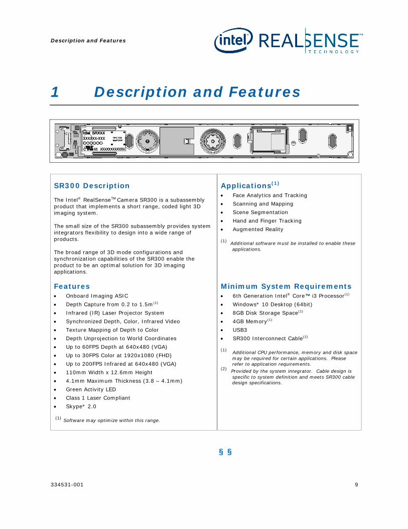
SR300 Description
The Intel® RealSenseTM Camera SR300 is a subassembly product that implements a short range, coded light 3D imaging system.
The small size of the SR300 subassembly provides system integrators flexibility to design into a wide range of products.
The broad range of 3D mode configurations and synchronization capabilities of the SR300 enable the product to be an optimal solution for 3D imaging applications.
Applications(1) • Face Analytics and Tracking • Scanning and Mapping • Scene Segmentation • Hand and Finger Tracking • Augmented Reality
(1) Additional software must be installed to enable these applications.
Features • Onboard Imaging ASIC • Depth Capture from 0.2 to 1.5m(1) • Infrared (IR) Laser Projector System • Synchronized Depth, Color, Infrared Video • Texture Mapping of Depth to Color • Depth Unprojection to World Coordinates • Up to 60FPS Depth at 640x480 (VGA) • Up to 30FPS Color at 1920x1080 (FHD) • Up to 200FPS Infrared at 640x480 (VGA) • 110mm Width x 12.6mm Height • 4.1mm Maximum Thickness (3.8 – 4.1mm) • Green Activity LED • Class 1 Laser Compliant • Skype* 2.0
(1) Software may optimize within this range.
Minimum System Requirements • 6th Generation Intel® Core™ i3 Processor(1) • Windows* 10 Desktop (64bit) • 8GB Disk Storage Space(1) • 4GB Memory(1) • USB3 • SR300 Interconnect Cable(2)
(1) Additional CPU performance, memory and disk space may be required for certain applications. Please refer to application requirements.
(2) Provided by the system integrator. Cable design is specific to system definition and meets SR300 cable design specifications.
§ §
Overview
10 334531-001
2 Overview 2.1 Components
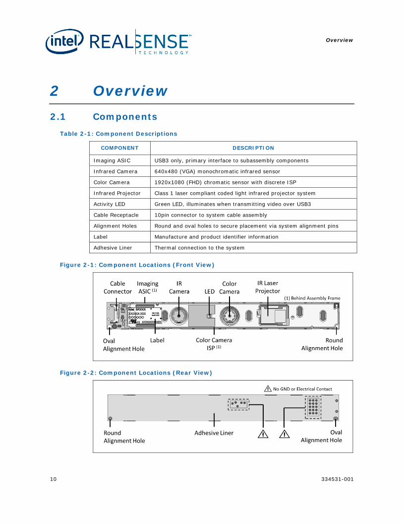
Table 2-1: Component Descriptions
COMPONENT DESCRIPTION
Imaging ASIC USB3 only, primary interface to subassembly components
Infrared Camera 640x480 (VGA) monochromatic infrared sensor
Color Camera 1920x1080 (FHD) chromatic sensor with discrete ISP
Infrared Projector Class 1 laser compliant coded light infrared projector system
Activity LED Green LED, illuminates when transmitting video over USB3
Cable Receptacle 10pin connector to system cable assembly
Alignment Holes Round and oval holes to secure placement via system alignment pins
Label Manufacture and product identifier information
Adhesive Liner Thermal connection to the system
Figure 2-1: Component Locations (Front View)
Figure 2-2: Component Locations (Rear View)
Overview
334531-001 11
2.2 Storage and Operating Conditions
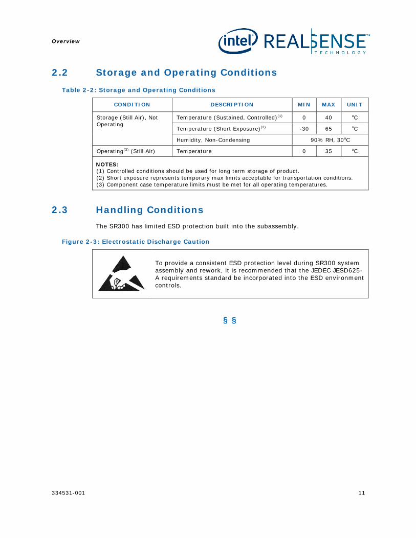
Table 2-2: Storage and Operating Conditions
CONDITION DESCRIPTION MIN MAX UNIT
Storage (Still Air), Not Operating
Temperature (Sustained, Controlled)(1) 0 40 oC
Temperature (Short Exposure)(2) -30 65 oC
Humidity, Non-Condensing 90% RH, 30oC
Operating(3) (Still Air) Temperature 0 35 oC
NOTES: (1) Controlled conditions should be used for long term storage of product. (2) Short exposure represents temporary max limits acceptable for transportation conditions. (3) Component case temperature limits must be met for all operating temperatures.
2.3 Handling Conditions The SR300 has limited ESD protection built into the subassembly.
Figure 2-3: Electrostatic Discharge Caution
To provide a consistent ESD protection level during SR300 system assembly and rework, it is recommended that the JEDEC JESD625-A requirements standard be incorporated into the ESD environment controls.
§ §
Component Specification
12 334531-001
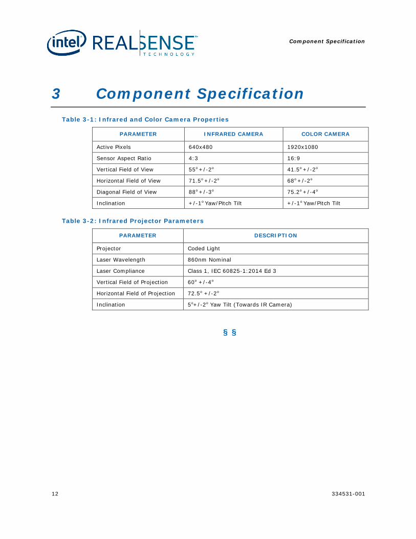
3 Component Specification Table 3-1: Infrared and Color Camera Properties
PARAMETER INFRARED CAMERA COLOR CAMERA
Active Pixels 640x480 1920x1080
Sensor Aspect Ratio 4:3 16:9
Vertical Field of View 55o +/-2o 41.5o +/-2o
Horizontal Field of View 71.5o +/-2o 68o +/-2o
Diagonal Field of View 88o +/-3o 75.2o +/-4o
Inclination +/-1o Yaw/Pitch Tilt +/-1o Yaw/Pitch Tilt
Table 3-2: Infrared Projector Parameters
PARAMETER DESCRIPTION
Projector Coded Light
Laser Wavelength 860nm Nominal
Laser Compliance Class 1, IEC 60825-1:2014 Ed 3
Vertical Field of Projection 60o +/-4o
Horizontal Field of Projection 72.5o +/-2o
Inclination 5o+/-2o Yaw Tilt (Towards IR Camera)
§ §
Functional Specification
334531-001 13
4 Functional Specification
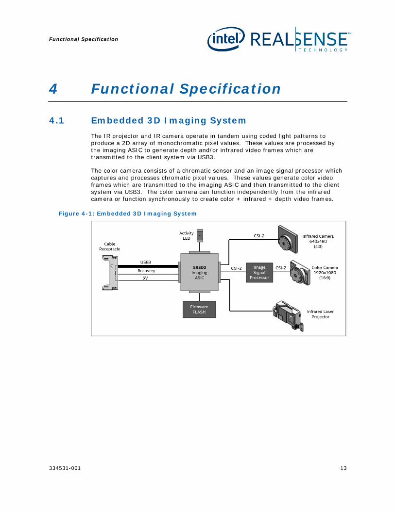
4.1 Embedded 3D Imaging System The IR projector and IR camera operate in tandem using coded light patterns to produce a 2D array of monochromatic pixel values. These values are processed by the imaging ASIC to generate depth and/or infrared video frames which are transmitted to the client system via USB3.
The color camera consists of a chromatic sensor and an image signal processor which captures and processes chromatic pixel values. These values generate color video frames which are transmitted to the imaging ASIC and then transmitted to the client system via USB3. The color camera can function independently from the infrared camera or function synchronously to create color + infrared + depth video frames.
Figure 4-1: Embedded 3D Imaging System
Functional Specification
14 334531-001
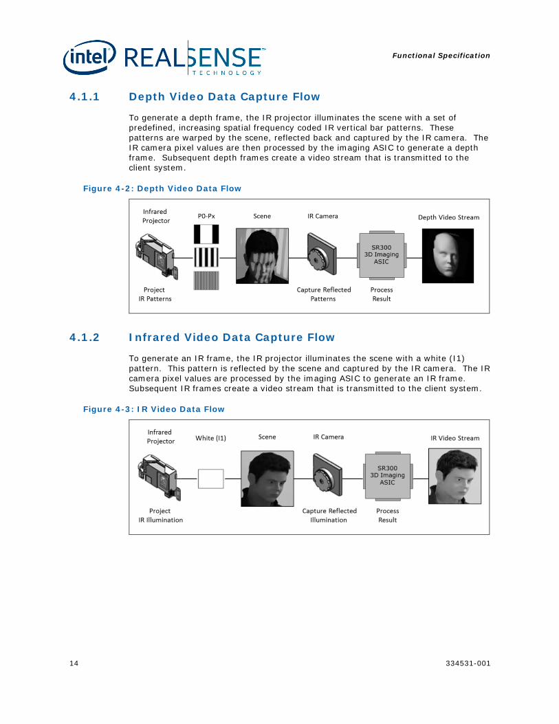
4.1.1 Depth Video Data Capture Flow
To generate a depth frame, the IR projector illuminates the scene with a set of predefined, increasing spatial frequency coded IR vertical bar patterns. These patterns are warped by the scene, reflected back and captured by the IR camera. The IR camera pixel values are then processed by the imaging ASIC to generate a depth frame. Subsequent depth frames create a video stream that is transmitted to the client system.
Figure 4-2: Depth Video Data Flow
4.1.2 Infrared Video Data Capture Flow
To generate an IR frame, the IR projector illuminates the scene with a white (I1) pattern. This pattern is reflected by the scene and captured by the IR camera. The IR camera pixel values are processed by the imaging ASIC to generate an IR frame. Subsequent IR frames create a video stream that is transmitted to the client system.
Figure 4-3: IR Video Data Flow
Functional Specification
334531-001 15
4.2 Camera Video Stream Formats
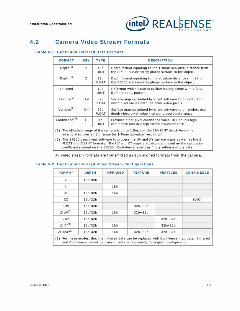
Table 4-1: Depth and Infrared Data Formats
FORMAT KEY TYPE DESCRIPTION
Depth(1) Z 16b UINT
Depth format equating to the 1/8mm sub-pixel distance from the SR300 subassembly planar surface to the object.
Depth(1) Z 32b FLOAT
Depth format equating to the absolute distance (mm) from the SR300 subassembly planar surface to the object.
Infrared I 10b UINT
IR format which equates to illuminating scene with a fully illuminated I1 pattern.
Texture(2) U,V 32b FLOAT
Surface map calculated by client software to project depth video pixel values onto the color video pixels.
Vertices(2) X,Y 32b FLOAT
Surface map calculated by client software to un-project each depth video pixel value into world coordinate space.
Confidence(2) C 4b UINT
Provides a per pixel confidence value, 0xF equals high confidence and 0x0 represents low confidence.
(1) The effective range of the camera is up to 1.5m, but the 16b UINT depth format is interpolated over an 8m range (or 1/8mm sub-pixel resolution).
(2) The SR300 uses client software to process the UV and XY surface maps as well as the Z FLOAT and C UINT formats. The UV and XY maps are calculated based on the calibration coefficients stored on the SR300. Confidence is sent as 4 bits within a single byte.
All video stream formats are transmitted as 16b aligned formats from the camera.
Table 4-2: Depth and Infrared Video Stream Configurations
FORMAT DEPTH INFRARED TEXTURE VERTICES CONFIDENCE
Z 16b/32b
I 16b
ZI 16b/32b 16b
ZC 16b/32b 8b(C)
ZUV 16b/32b 32b+32b
ZIUV(1) 16b/32b 16b 32b+32b
ZXY 16b/32b 32b+32b
ZIXY(1) 16b/32b 16b 32b+32b
ZIUVXY(1) 16b/32b 16b 32b+32b 32b+32b
(1) For these modes, the, the Infrared data can be replaced with Confidence map data. Infrared and Confidence cannot be transmitted simultaneously for a given configuration.
Functional Specification
16 334531-001
4.3 Camera Video Stream Modes
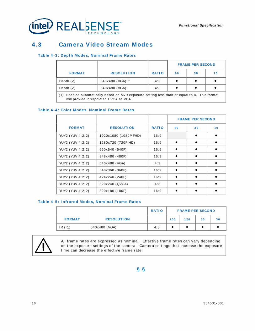
Table 4-3: Depth Modes, Nominal Frame Rates
FORMAT RESOLUTION RATIO
FRAME PER SECOND
60 30 10
Depth (Z) 640x480 (VGA)(1) 4:3 • • •
Depth (Z) 640x480 (VGA) 4:3 • • •
(1) Enabled automatically based on MvR exposure setting less than or equal to 8. This format will provide interpolated HVGA as VGA.
Table 4-4: Color Modes, Nominal Frame Rates
FORMAT RESOLUTION RATIO
FRAME PER SECOND
60 30 10
YUY2 (YUV 4:2:2) 1920x1080 (1080P FHD) 16:9 • •
YUY2 (YUV 4:2:2) 1280x720 (720P HD) 16:9 • • •
YUY2 (YUV 4:2:2) 960x540 (540P) 16:9 • • •
YUY2 (YUV 4:2:2) 848x480 (480P) 16:9 • • •
YUY2 (YUV 4:2:2) 640x480 (VGA) 4:3 • • •
YUY2 (YUV 4:2:2) 640x360 (360P) 16:9 • • •
YUY2 (YUV 4:2:2) 424x240 (240P) 16:9 • • •
YUY2 (YUV 4:2:2) 320x240 (QVGA) 4:3 • • •
YUY2 (YUV 4:2:2) 320x180 (180P) 16:9 • • •
Table 4-5: Infrared Modes, Nominal Frame Rates
FORMAT RESOLUTION
RATIO FRAME PER SECOND
200 120 60 30
IR (I1) 640x480 (VGA) 4:3 • • • •
All frame rates are expressed as nominal. Effective frame rates can vary depending on the exposure settings of the camera. Camera settings that increase the exposure time can decrease the effective frame rate.
§ §

Firmware Update
334531-001 17
5 Firmware Update
5.1 Update During a firmware update, the firmware utility will issue a device firmware update command to the SR300. The SR300 will then reset into firmware update mode. The firmware utility uses a single binary file to maintain the firmware image and is executed during the DCM system software installation. The firmware utility compares the firmware version installed on the camera to the firmware version file to be updated. Based on the comparison, the firmware utility will downgrade, upgrade, or skip if the versions match.
The firmware version programmed by the firmware utility is tightly coupled with the DCM runtime version. This is why the firmware utility is bundled with the DCM system software installer and should not be decoupled. If there is a mismatch between firmware and DCM versions, features can cease to function or unknown behaviors can occur.
5.1.1 Update Limits
The firmware update engine does not allow infinite update cycles between older and current versions of firmware. The engine will establish a baseline version of firmware based on the latest firmware version installed. The engine will allow a return to a previous version or baseline version of firmware up to 20 times. After the 20th update, the engine will only allow an update to a firmware revision higher than the baseline version.
5.2 Recovery A read only boot sector is built into firmware which enables basic operation regardless of the integrity of the operation instructions region. This ensures the SR300 can function in the case of firmware not be written properly. When a firmware recovery is required, the firmware utility will communicate with the recovery driver to set the interrupt pin low and reset the SR300 in recovery mode.
Recovery is only supported if the system BIOS implements the INT33A3 HID device and methods for interrupt and power control. The recovery driver installation and recovery functions will FAIL if not implemented.
§ §
Client Software
18 334531-001
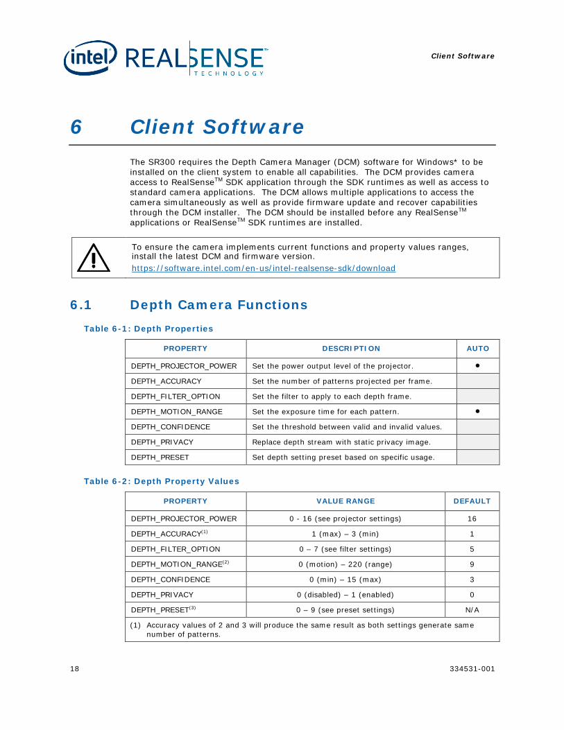
6 Client Software The SR300 requires the Depth Camera Manager (DCM) software for Windows* to be installed on the client system to enable all capabilities. The DCM provides camera access to RealSenseTM SDK application through the SDK runtimes as well as access to standard camera applications. The DCM allows multiple applications to access the camera simultaneously as well as provide firmware update and recover capabilities through the DCM installer. The DCM should be installed before any RealSenseTM applications or RealSenseTM SDK runtimes are installed.
To ensure the camera implements current functions and property values ranges, install the latest DCM and firmware version. https://software.intel.com/en-us/intel-realsense-sdk/download
6.1 Depth Camera Functions
Table 6-1: Depth Properties
PROPERTY DESCRIPTION AUTO
DEPTH_PROJECTOR_POWER Set the power output level of the projector. •
DEPTH_ACCURACY Set the number of patterns projected per frame.
DEPTH_FILTER_OPTION Set the filter to apply to each depth frame.
DEPTH_MOTION_RANGE Set the exposure time for each pattern. •
DEPTH_CONFIDENCE Set the threshold between valid and invalid values.
DEPTH_PRIVACY Replace depth stream with static privacy image.
DEPTH_PRESET Set depth setting preset based on specific usage.
Table 6-2: Depth Property Values
PROPERTY VALUE RANGE DEFAULT
DEPTH_PROJECTOR_POWER 0 - 16 (see projector settings) 16
DEPTH_ACCURACY(1) 1 (max) – 3 (min) 1
DEPTH_FILTER_OPTION 0 – 7 (see filter settings) 5
DEPTH_MOTION_RANGE(2) 0 (motion) – 220 (range) 9
DEPTH_CONFIDENCE 0 (min) – 15 (max) 3
DEPTH_PRIVACY 0 (disabled) – 1 (enabled) 0
DEPTH_PRESET(3) 0 – 9 (see preset settings) N/A
(1) Accuracy values of 2 and 3 will produce the same result as both settings generate same number of patterns.
Client Software
334531-001 19
PROPERTY VALUE RANGE DEFAULT
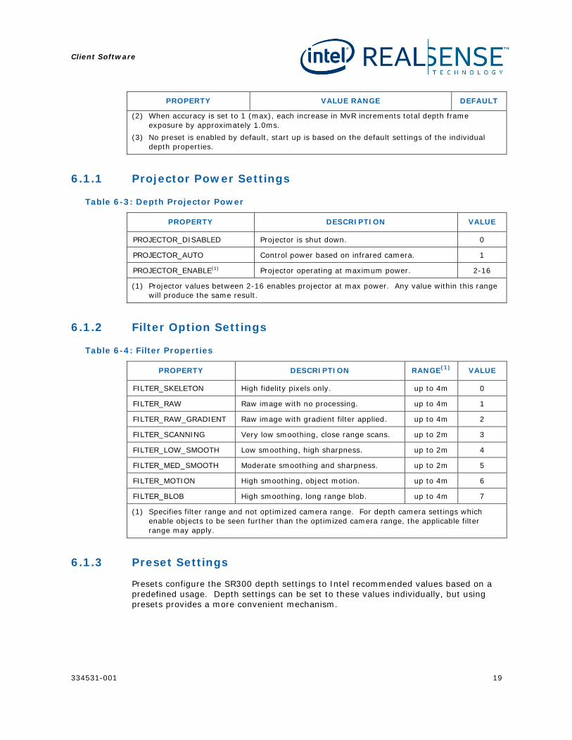
(2) When accuracy is set to 1 (max), each increase in MvR increments total depth frame exposure by approximately 1.0ms.
(3) No preset is enabled by default, start up is based on the default settings of the individual depth properties.
6.1.1 Projector Power Settings
Table 6-3: Depth Projector Power
PROPERTY DESCRIPTION VALUE
PROJECTOR_DISABLED Projector is shut down. 0
PROJECTOR_AUTO Control power based on infrared camera. 1
PROJECTOR_ENABLE(1) Projector operating at maximum power. 2-16
(1) Projector values between 2-16 enables projector at max power. Any value within this range will produce the same result.
6.1.2 Filter Option Settings
Table 6-4: Filter Properties
PROPERTY DESCRIPTION RANGE(1) VALUE
FILTER_SKELETON High fidelity pixels only. up to 4m 0
FILTER_RAW Raw image with no processing. up to 4m 1
FILTER_RAW_GRADIENT Raw image with gradient filter applied. up to 4m 2
FILTER_SCANNING Very low smoothing, close range scans. up to 2m 3
FILTER_LOW_SMOOTH Low smoothing, high sharpness. up to 2m 4
FILTER_MED_SMOOTH Moderate smoothing and sharpness. up to 2m 5
FILTER_MOTION High smoothing, object motion. up to 4m 6
FILTER_BLOB High smoothing, long range blob. up to 4m 7
(1) Specifies filter range and not optimized camera range. For depth camera settings which enable objects to be seen further than the optimized camera range, the applicable filter range may apply.
6.1.3 Preset Settings
Presets configure the SR300 depth settings to Intel recommended values based on a predefined usage. Depth settings can be set to these values individually, but using presets provides a more convenient mechanism.
Client Software
20 334531-001
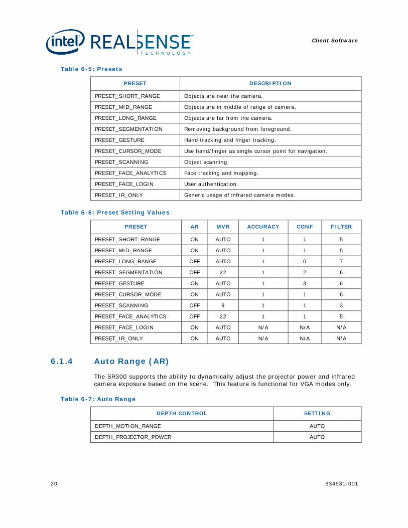
Table 6-5: Presets
PRESET DESCRIPTION
PRESET_SHORT_RANGE Objects are near the camera.
PRESET_MID_RANGE Objects are in middle of range of camera.
PRESET_LONG_RANGE Objects are far from the camera.
PRESET_SEGMENTATION Removing background from foreground.
PRESET_GESTURE Hand tracking and finger tracking.
PRESET_CURSOR_MODE Use hand/finger as single cursor point for navigation.
PRESET_SCANNING Object scanning.
PRESET_FACE_ANALYTICS Face tracking and mapping.
PRESET_FACE_LOGIN User authentication.
PRESET_IR_ONLY Generic usage of infrared camera modes.
Table 6-6: Preset Setting Values
PRESET AR MVR ACCURACY CONF FILTER
PRESET_SHORT_RANGE ON AUTO 1 1 5
PRESET_MID_RANGE ON AUTO 1 1 5
PRESET_LONG_RANGE OFF AUTO 1 0 7
PRESET_SEGMENTATION OFF 22 1 2 6
PRESET_GESTURE ON AUTO 1 3 6
PRESET_CURSOR_MODE ON AUTO 1 1 6
PRESET_SCANNING OFF 9 1 1 3
PRESET_FACE_ANALYTICS OFF 22 1 1 5
PRESET_FACE_LOGIN ON AUTO N/A N/A N/A
PRESET_IR_ONLY ON AUTO N/A N/A N/A
6.1.4 Auto Range (AR)
The SR300 supports the ability to dynamically adjust the projector power and infrared camera exposure based on the scene. This feature is functional for VGA modes only.
Table 6-7: Auto Range
DEPTH CONTROL SETTING
DEPTH_MOTION_RANGE AUTO
DEPTH_PROJECTOR_POWER AUTO
Client Software
334531-001 21
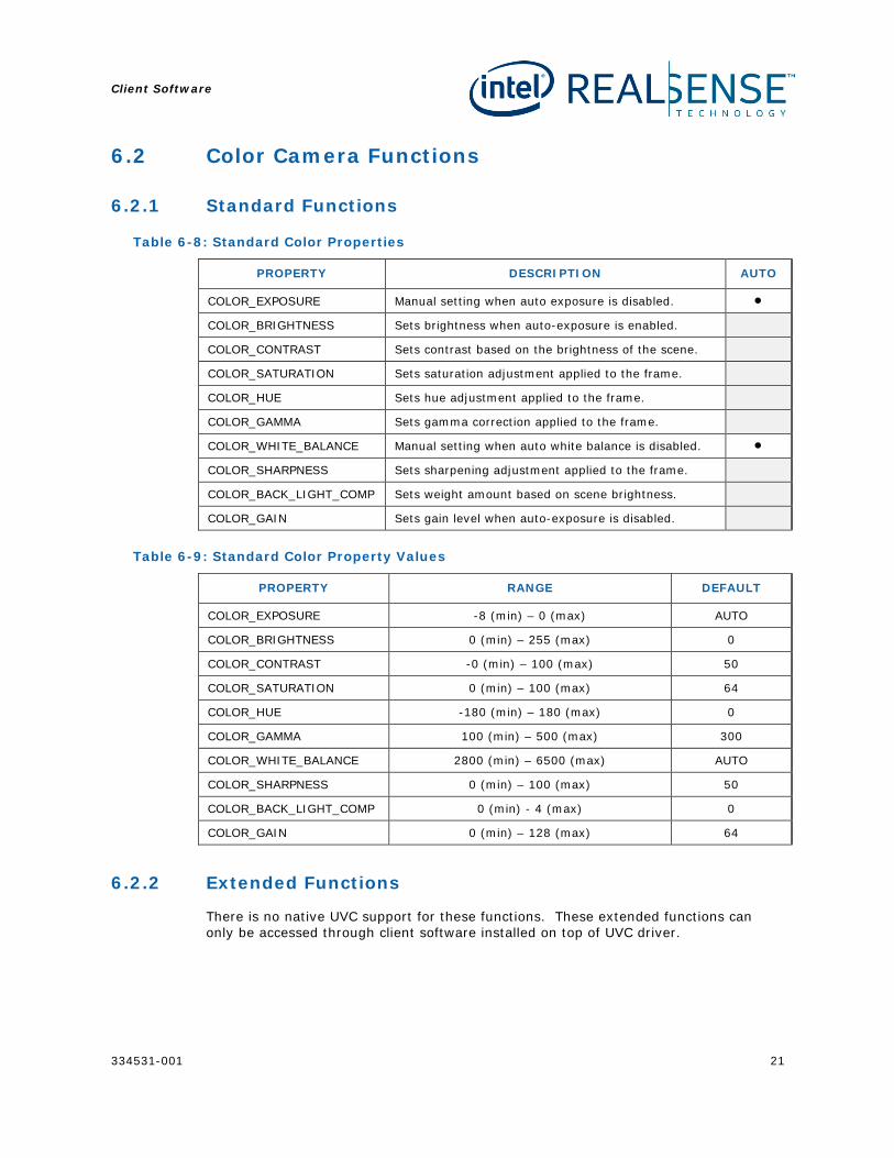
6.2 Color Camera Functions
6.2.1 Standard Functions
Table 6-8: Standard Color Properties
PROPERTY DESCRIPTION AUTO
COLOR_EXPOSURE Manual setting when auto exposure is disabled. •
COLOR_BRIGHTNESS Sets brightness when auto-exposure is enabled.
COLOR_CONTRAST Sets contrast based on the brightness of the scene.
COLOR_SATURATION Sets saturation adjustment applied to the frame.
COLOR_HUE Sets hue adjustment applied to the frame.
COLOR_GAMMA Sets gamma correction applied to the frame.
COLOR_WHITE_BALANCE Manual setting when auto white balance is disabled. •
COLOR_SHARPNESS Sets sharpening adjustment applied to the frame.
COLOR_BACK_LIGHT_COMP Sets weight amount based on scene brightness.
COLOR_GAIN Sets gain level when auto-exposure is disabled.
Table 6-9: Standard Color Property Values
PROPERTY RANGE DEFAULT
COLOR_EXPOSURE -8 (min) – 0 (max) AUTO
COLOR_BRIGHTNESS 0 (min) – 255 (max) 0
COLOR_CONTRAST -0 (min) – 100 (max) 50
COLOR_SATURATION 0 (min) – 100 (max) 64
COLOR_HUE -180 (min) – 180 (max) 0
COLOR_GAMMA 100 (min) – 500 (max) 300
COLOR_WHITE_BALANCE 2800 (min) – 6500 (max) AUTO
COLOR_SHARPNESS 0 (min) – 100 (max) 50
COLOR_BACK_LIGHT_COMP 0 (min) - 4 (max) 0
COLOR_GAIN 0 (min) – 128 (max) 64
6.2.2 Extended Functions
There is no native UVC support for these functions. These extended functions can only be accessed through client software installed on top of UVC driver.
Client Software
22 334531-001
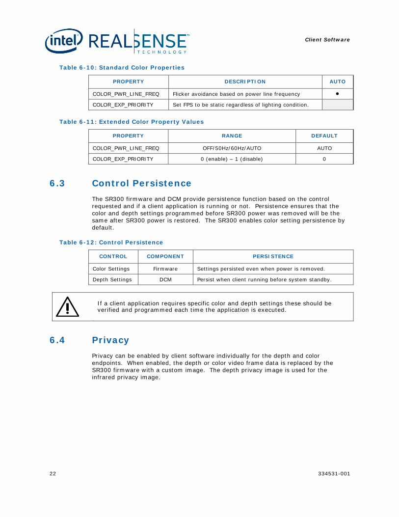
Table 6-10: Standard Color Properties
PROPERTY DESCRIPTION AUTO
COLOR_PWR_LINE_FREQ Flicker avoidance based on power line frequency •
COLOR_EXP_PRIORITY Set FPS to be static regardless of lighting condition.
Table 6-11: Extended Color Property Values
PROPERTY RANGE DEFAULT
COLOR_PWR_LINE_FREQ OFF/50Hz/60Hz/AUTO AUTO
COLOR_EXP_PRIORITY 0 (enable) – 1 (disable) 0
6.3 Control Persistence The SR300 firmware and DCM provide persistence function based on the control requested and if a client application is running or not. Persistence ensures that the color and depth settings programmed before SR300 power was removed will be the same after SR300 power is restored. The SR300 enables color setting persistence by default.
Table 6-12: Control Persistence
CONTROL COMPONENT PERSISTENCE
Color Settings Firmware Settings persisted even when power is removed.
Depth Settings DCM Persist when client running before system standby.
If a client application requires specific color and depth settings these should be verified and programmed each time the application is executed.
6.4 Privacy Privacy can be enabled by client software individually for the depth and color endpoints. When enabled, the depth or color video frame data is replaced by the SR300 firmware with a custom image. The depth privacy image is used for the infrared privacy image.
Client Software
334531-001 23
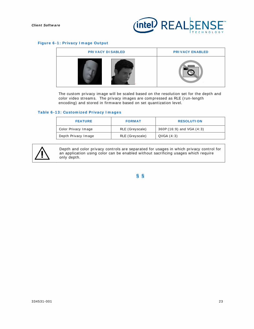
Figure 6-1: Privacy Image Output
PRIVACY DISABLED PRIVACY ENABLED
The custom privacy image will be scaled based on the resolution set for the depth and color video streams. The privacy images are compressed as RLE (run-length encoding) and stored in firmware based on set quantization level.
Table 6-13: Customized Privacy Images
FEATURE FORMAT RESOLUTION
Color Privacy Image RLE (Greyscale) 360P (16:9) and VGA (4:3)
Depth Privacy Image RLE (Greyscale) QVGA (4:3)
Depth and color privacy controls are separated for usages in which privacy control for an application using color can be enabled without sacrificing usages which require only depth.
§ §
System Interoperability
24 334531-001
7 System Interoperability
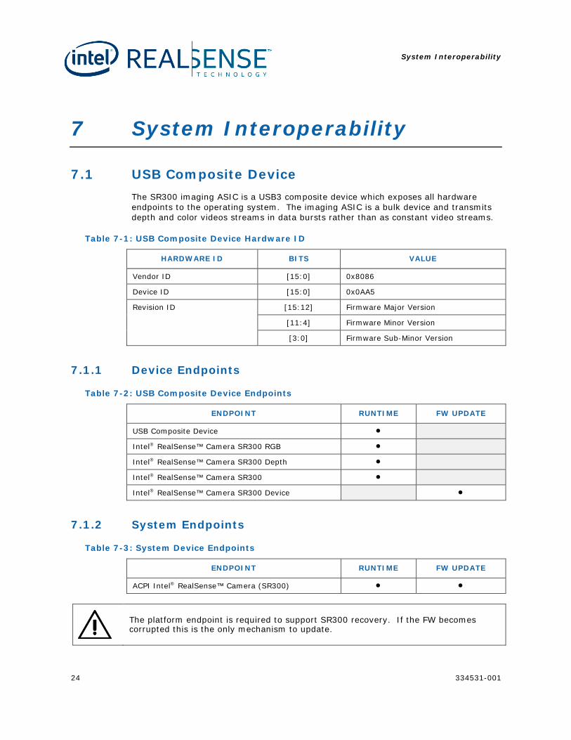
7.1 USB Composite Device The SR300 imaging ASIC is a USB3 composite device which exposes all hardware endpoints to the operating system. The imaging ASIC is a bulk device and transmits depth and color videos streams in data bursts rather than as constant video streams.
Table 7-1: USB Composite Device Hardware ID
HARDWARE ID BITS VALUE
Vendor ID [15:0] 0x8086
Device ID [15:0] 0x0AA5
Revision ID [15:12] Firmware Major Version
[11:4] Firmware Minor Version
[3:0] Firmware Sub-Minor Version
7.1.1 Device Endpoints
Table 7-2: USB Composite Device Endpoints
ENDPOINT RUNTIME FW UPDATE
USB Composite Device •
Intel® RealSense™ Camera SR300 RGB •
Intel® RealSense™ Camera SR300 Depth •
Intel® RealSense™ Camera SR300 •
Intel® RealSense™ Camera SR300 Device •
7.1.2 System Endpoints
Table 7-3: System Device Endpoints
ENDPOINT RUNTIME FW UPDATE
ACPI Intel® RealSense™ Camera (SR300) • •
The platform endpoint is required to support SR300 recovery. If the FW becomes corrupted this is the only mechanism to update.
System Interoperability
334531-001 25
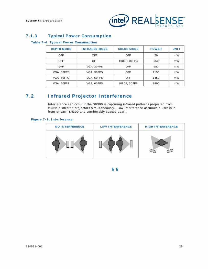
7.1.3 Typical Power Consumption Table 7-4: Typical Power Consumption
DEPTH MODE INFRARED MODE COLOR MODE POWER UNIT
OFF OFF OFF 20 mW
OFF OFF 1080P, 30FPS 650 mW
OFF VGA, 30FPS OFF 980 mW
VGA, 30FPS VGA, 30FPS OFF 1150 mW
VGA, 60FPS VGA, 60FPS OFF 1450 mW
VGA, 60FPS VGA, 60FPS 1080P, 30FPS 1800 mW
7.2 Infrared Projector Interference Interference can occur if the SR300 is capturing infrared patterns projected from multiple infrared projectors simultaneously. Low interference assumes a user is in front of each SR300 and comfortably spaced apart.
Figure 7-1: Interference
NO INTERFERENCE LOW INTERFERENCE HIGH INTERFERENCE
§ §
System Integration
26 334531-001
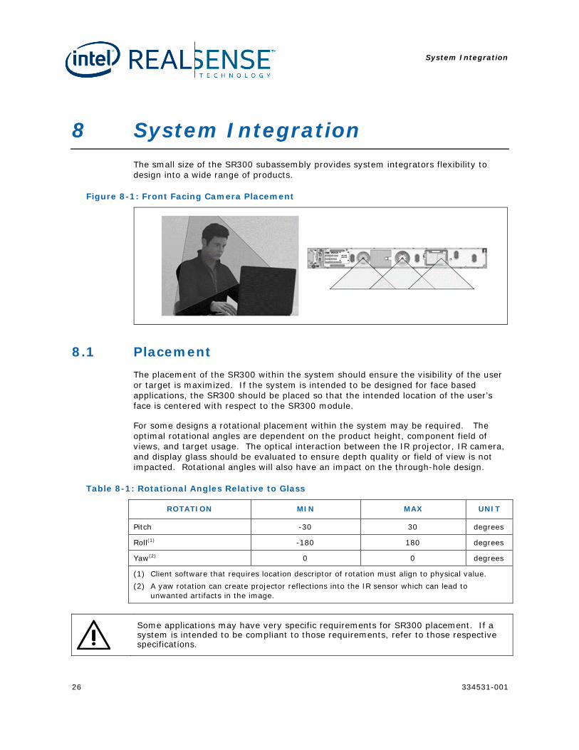
8 System Integration The small size of the SR300 subassembly provides system integrators flexibility to design into a wide range of products.
Figure 8-1: Front Facing Camera Placement
8.1 Placement The placement of the SR300 within the system should ensure the visibility of the user or target is maximized. If the system is intended to be designed for face based applications, the SR300 should be placed so that the intended location of the user’s face is centered with respect to the SR300 module.
For some designs a rotational placement within the system may be required. The optimal rotational angles are dependent on the product height, component field of views, and target usage. The optical interaction between the IR projector, IR camera, and display glass should be evaluated to ensure depth quality or field of view is not impacted. Rotational angles will also have an impact on the through-hole design.
Table 8-1: Rotational Angles Relative to Glass
ROTATION MIN MAX UNIT
Pitch -30 30 degrees
Roll(1) -180 180 degrees
Yaw(2) 0 0 degrees
(1) Client software that requires location descriptor of rotation must align to physical value. (2) A yaw rotation can create projector reflections into the IR sensor which can lead to
unwanted artifacts in the image.
Some applications may have very specific requirements for SR300 placement. If a system is intended to be compliant to those requirements, refer to those respective specifications.
System Integration
334531-001 27
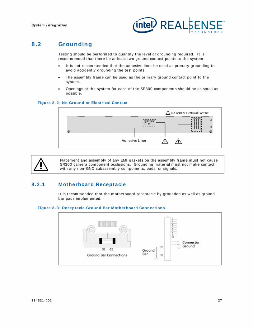
8.2 Grounding Testing should be performed to quantify the level of grounding required. It is recommended that there be at least two ground contact points to the system.
• It is not recommended that the adhesive liner be used as primary grounding to avoid accidently grounding the test points.
• The assembly frame can be used as the primary ground contact point to the system.
• Openings at the system for each of the SR300 components should be as small as possible.
Figure 8-2: No Ground or Electrical Contact
Placement and assembly of any EMI gaskets on the assembly frame must not cause SR300 camera component occlusions. Grounding material must not make contact with any non-GND subassembly components, pads, or signals.
8.2.1 Motherboard Receptacle
It is recommended that the motherboard receptacle by grounded as well as ground bar pads implemented.
Figure 8-3: Receptacle Ground Bar Motherboard Connections
System Integration
28 334531-001
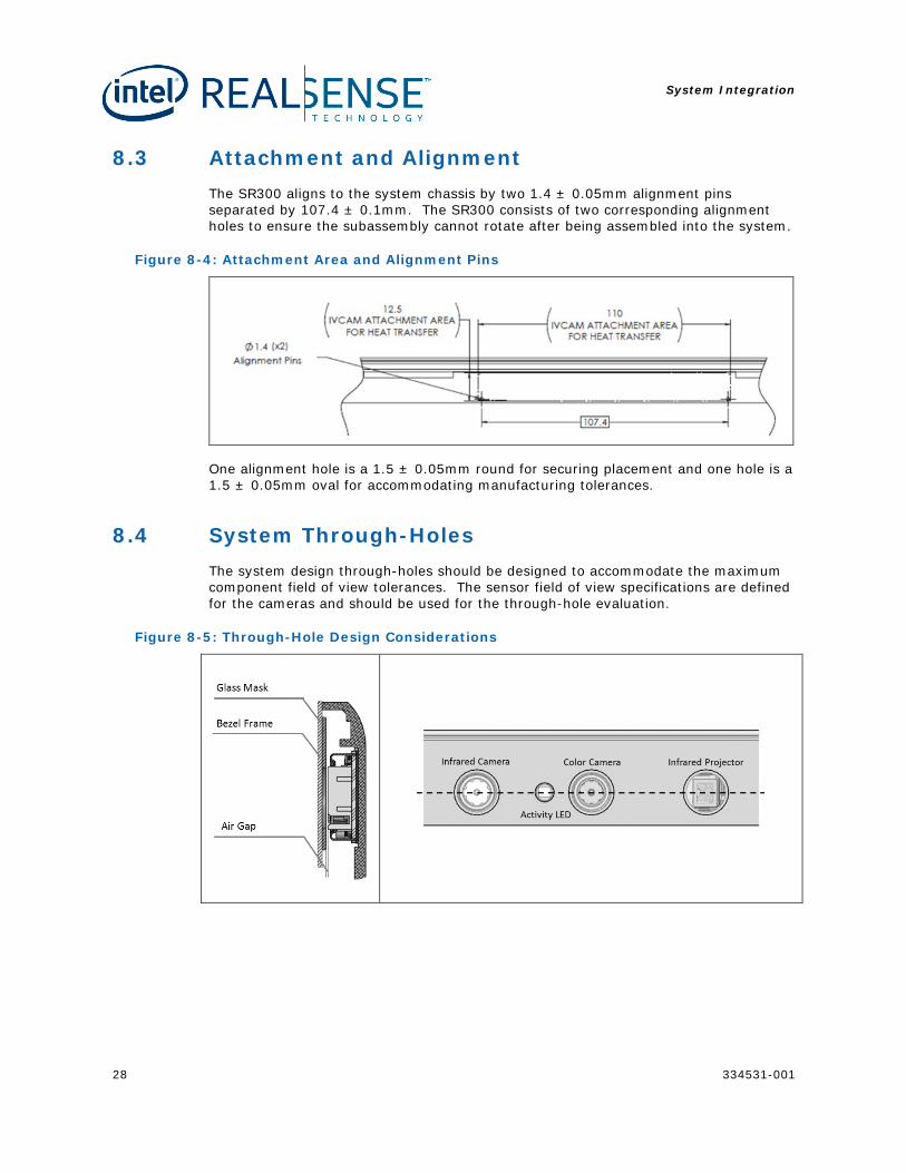
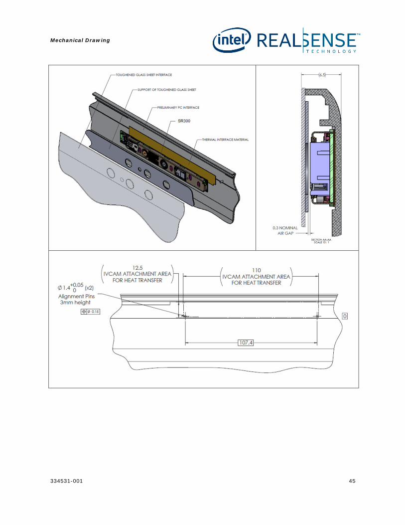
8.3 Attachment and Alignment The SR300 aligns to the system chassis by two 1.4 ± 0.05mm alignment pins separated by 107.4 ± 0.1mm. The SR300 consists of two corresponding alignment holes to ensure the subassembly cannot rotate after being assembled into the system.
Figure 8-4: Attachment Area and Alignment Pins
One alignment hole is a 1.5 ± 0.05mm round for securing placement and one hole is a 1.5 ± 0.05mm oval for accommodating manufacturing tolerances.
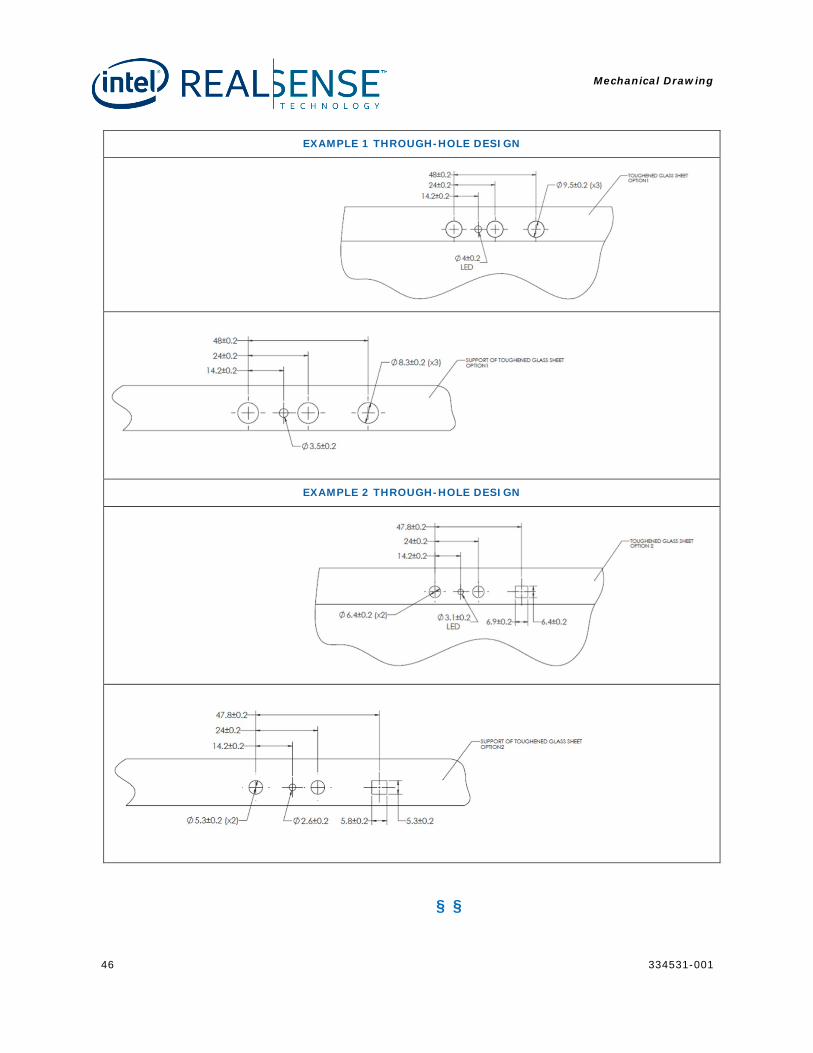
8.4 System Through-Holes The system design through-holes should be designed to accommodate the maximum component field of view tolerances. The sensor field of view specifications are defined for the cameras and should be used for the through-hole evaluation.
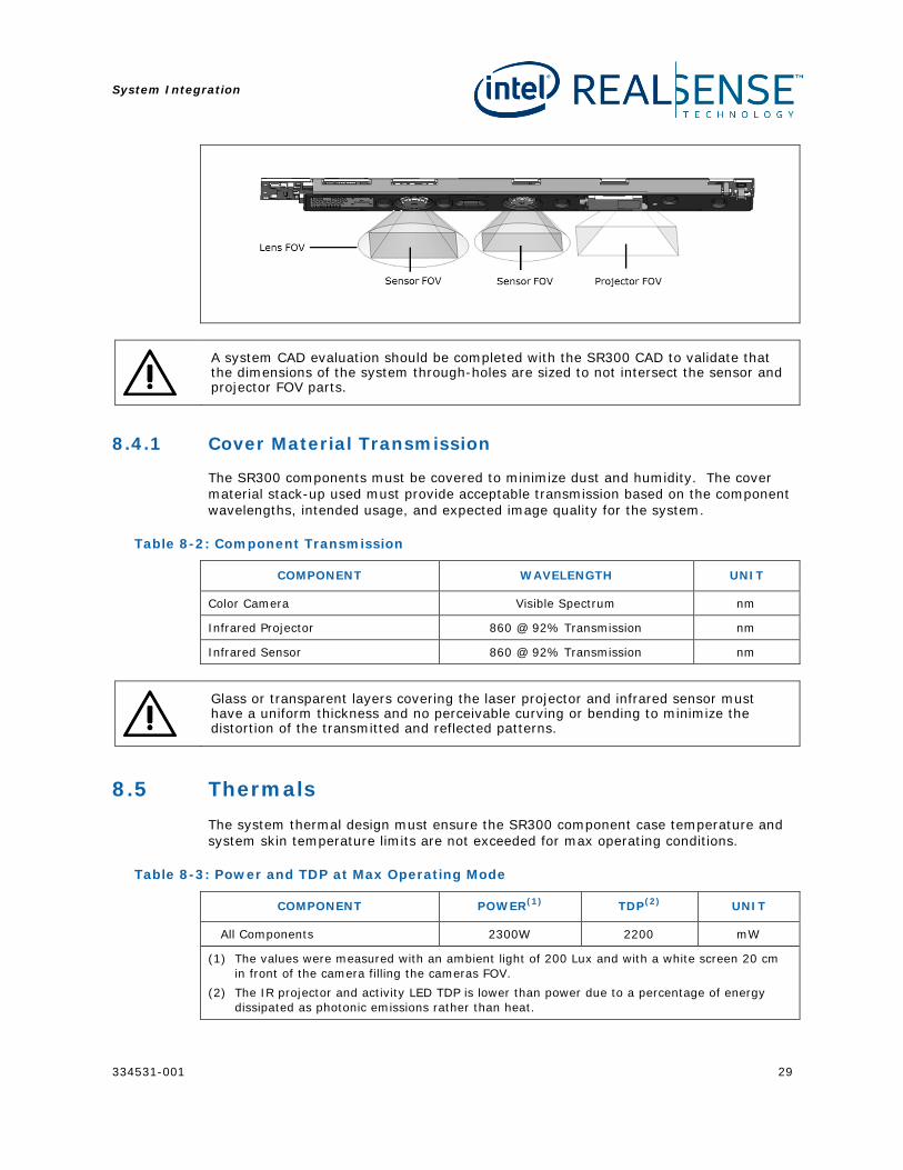
Figure 8-5: Through-Hole Design Considerations
System Integration
334531-001 29
A system CAD evaluation should be completed with the SR300 CAD to validate that the dimensions of the system through-holes are sized to not intersect the sensor and projector FOV parts.
8.4.1 Cover Material Transmission
The SR300 components must be covered to minimize dust and humidity. The cover material stack-up used must provide acceptable transmission based on the component wavelengths, intended usage, and expected image quality for the system.
Table 8-2: Component Transmission
COMPONENT WAVELENGTH UNIT
Color Camera Visible Spectrum nm
Infrared Projector 860 @ 92% Transmission nm
Infrared Sensor 860 @ 92% Transmission nm
Glass or transparent layers covering the laser projector and infrared sensor must have a uniform thickness and no perceivable curving or bending to minimize the distortion of the transmitted and reflected patterns.
8.5 Thermals The system thermal design must ensure the SR300 component case temperature and system skin temperature limits are not exceeded for max operating conditions.
Table 8-3: Power and TDP at Max Operating Mode
COMPONENT POWER(1) TDP(2) UNIT
All Components 2300W 2200 mW
(1) The values were measured with an ambient light of 200 Lux and with a white screen 20 cm in front of the camera filling the cameras FOV.
(2) The IR projector and activity LED TDP is lower than power due to a percentage of energy dissipated as photonic emissions rather than heat.
System Integration
30 334531-001
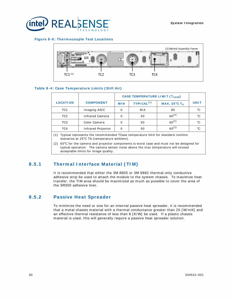
Figure 8-6: Thermocouple Test Locations
Table 8-4: Case Temperature Limits (Still Air)
LOCATION COMPONENT
CASE TEMPERATURE LIMIT (TCASE)
UNIT MIN TYPICAL(1) MAX, 35oC TA
TC1 Imaging ASIC 0 N/A 85 oC
TC2 Infrared Camera 0 50 60(2) oC
TC3 Color Camera 0 50 60(2) oC
TC4 Infrared Projector 0 50 60(2) oC
(1) Typical represents the recommended TCase temperature limit for standard runtime scenarios at 25oC TA (temperature ambient).
(2) 60oC for the camera and projector components is worst case and must not be designed for typical operation. The camera sensor noise above the max temperature will exceed acceptable limits for image quality.
8.5.1 Thermal Interface Material (TIM)
It is recommended that either the 3M 8805 or 3M 9882 thermal-only conductive adhesive strip be used to attach the module to the system chassis. To maximize heat transfer, the TIM area should be maximized as much as possible to cover the area of the SR300 adhesive liner.
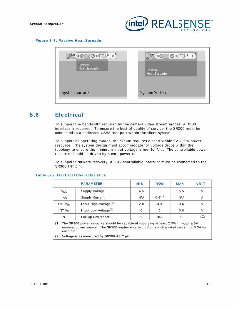
8.5.2 Passive Heat Spreader
To minimize the need or size for an internal passive heat spreader, it is recommended that a metal chassis material with a thermal conductance greater than 20 [W/mK] and an effective thermal resistance of less than 8 [K/W] be used. If a plastic chassis material is used, this will generally require a passive heat spreader solution.
System Integration
334531-001 31
Figure 8-7: Passive Heat Spreader
8.6 Electrical To support the bandwidth required by the camera video stream modes, a USB3 interface is required. To ensure the best of quality of service, the SR300 must be connected to a dedicated USB3 root port within the client system.
To support all operating modes, the SR300 requires a controllable 5V ± 5% power resource. The system design must accommodate for voltage drops within the topology to ensure the minimum input voltage is met for VDD. The controllable power resource should be driven by a core power rail.
To support firmware recovery, a 3.3V controllable interrupt must be connected to the SR300 INT pin.
Table 8-5: Electrical Characteristics
PARAMETER MIN NOM MAX UNIT
VDD Supply Voltage 4.5 5 5.5 V
IDD Supply Current N/A 0.6(1) N/A A
INT VIH Input High Voltage(2) 2.0 3.3 3.6 V
INT VIL Input Low Voltage(2) 0 0 0.8 V
INT Pull Up Resistance 20 N/A 60 kΩ
(1) The SR300 power resource should be capable of supplying at least 2.5W through a 5V nominal power source. The SR300 implements two 5V pins with a rated current of 0.3A for each pin.
(2) Voltage is as measured by SR300 ASIC pin.
System Integration
32 334531-001
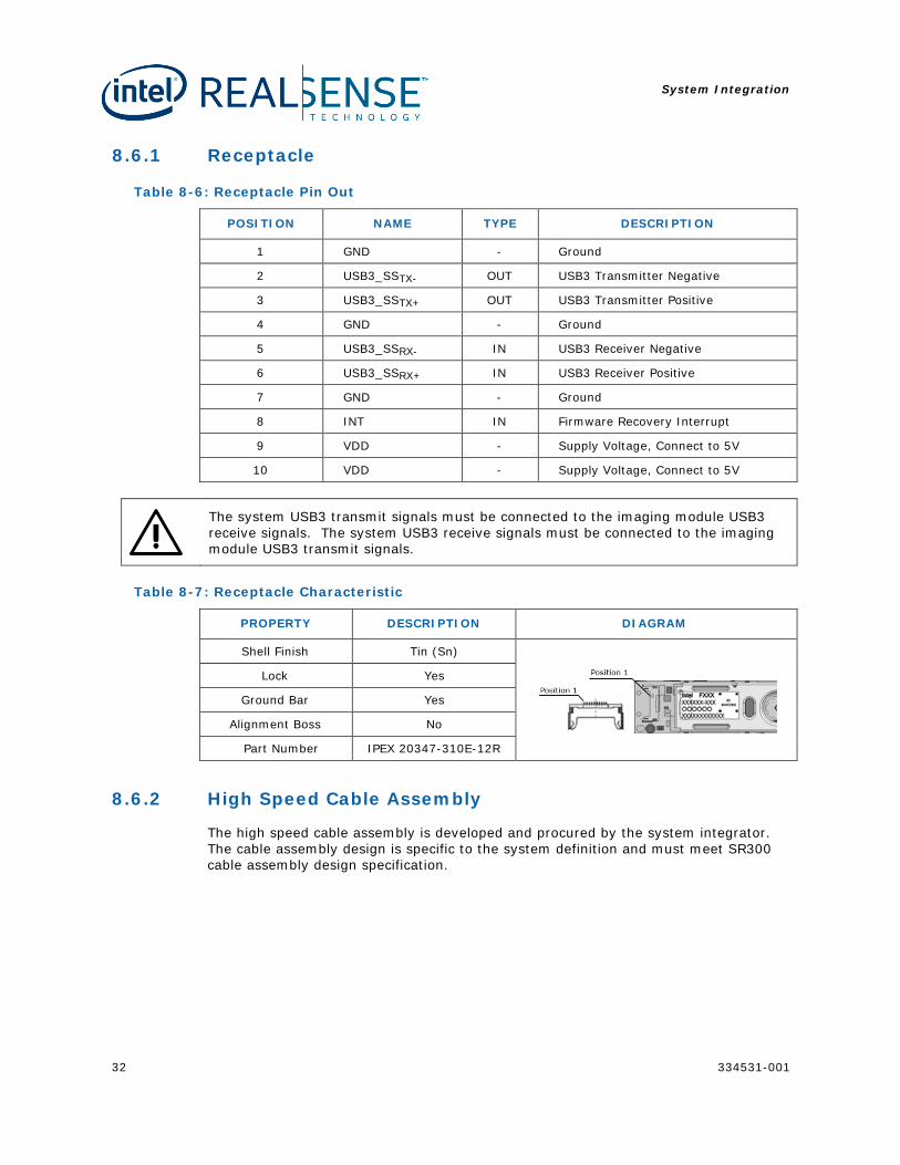
8.6.1 Receptacle
Table 8-6: Receptacle Pin Out
POSITION NAME TYPE DESCRIPTION
1 GND - Ground
2 USB3_SSTX- OUT USB3 Transmitter Negative
3 USB3_SSTX+ OUT USB3 Transmitter Positive
4 GND - Ground
5 USB3_SSRX- IN USB3 Receiver Negative
6 USB3_SSRX+ IN USB3 Receiver Positive
7 GND - Ground
8 INT IN Firmware Recovery Interrupt
9 VDD - Supply Voltage, Connect to 5V
10 VDD - Supply Voltage, Connect to 5V
The system USB3 transmit signals must be connected to the imaging module USB3 receive signals. The system USB3 receive signals must be connected to the imaging module USB3 transmit signals.
Table 8-7: Receptacle Characteristic
PROPERTY DESCRIPTION DIAGRAM
Shell Finish Tin (Sn)
Lock Yes
Ground Bar Yes
Alignment Boss No
Part Number IPEX 20347-310E-12R
8.6.2 High Speed Cable Assembly
The high speed cable assembly is developed and procured by the system integrator. The cable assembly design is specific to the system definition and must meet SR300 cable assembly design specification.
System Integration
334531-001 33
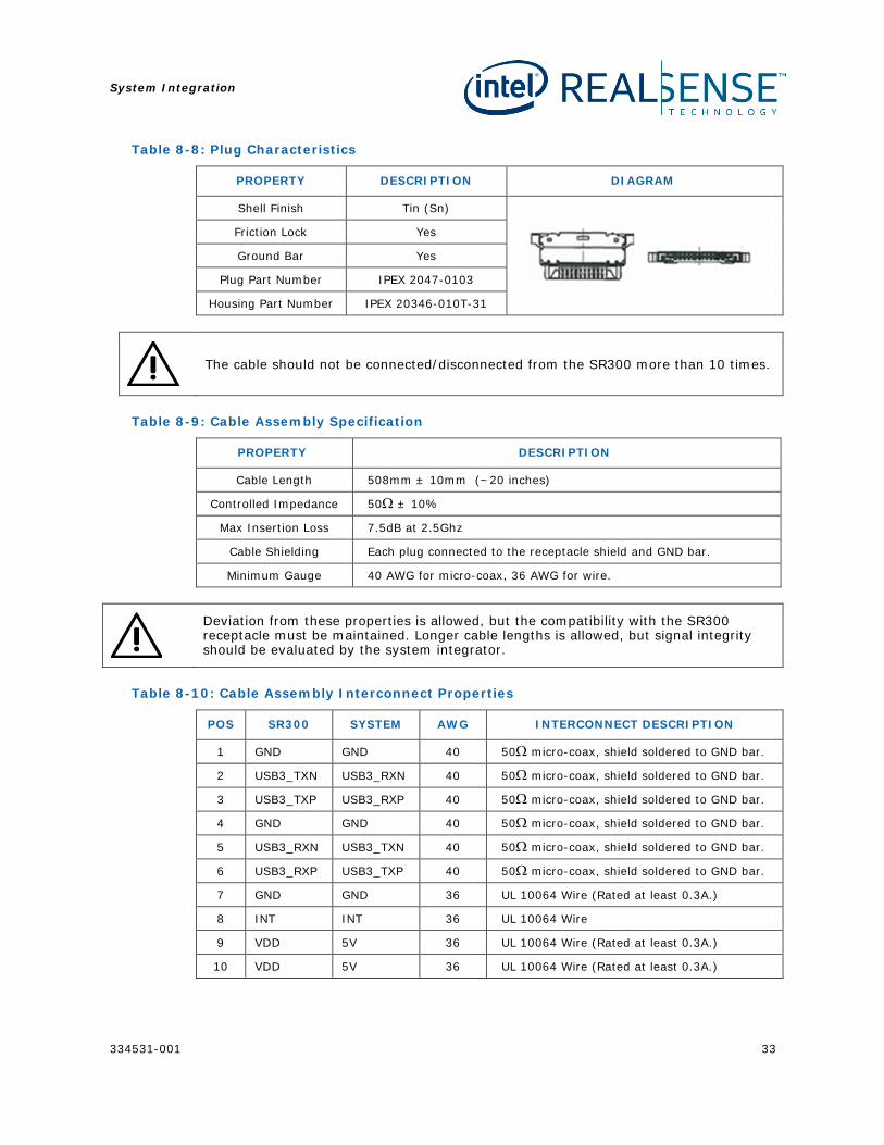
Table 8-8: Plug Characteristics
PROPERTY DESCRIPTION DIAGRAM
Shell Finish Tin (Sn)
Friction Lock Yes
Ground Bar Yes
Plug Part Number IPEX 2047-0103
Housing Part Number IPEX 20346-010T-31
The cable should not be connected/disconnected from the SR300 more than 10 times.
Table 8-9: Cable Assembly Specification
PROPERTY DESCRIPTION
Cable Length 508mm ± 10mm (~20 inches)
Controlled Impedance 50Ω ± 10%
Max Insertion Loss 7.5dB at 2.5Ghz
Cable Shielding Each plug connected to the receptacle shield and GND bar.
Minimum Gauge 40 AWG for micro-coax, 36 AWG for wire.
Deviation from these properties is allowed, but the compatibility with the SR300 receptacle must be maintained. Longer cable lengths is allowed, but signal integrity should be evaluated by the system integrator.
Table 8-10: Cable Assembly Interconnect Properties
POS SR300 SYSTEM AWG INTERCONNECT DESCRIPTION
1 GND GND 40 50Ω micro-coax, shield soldered to GND bar.
2 USB3_TXN USB3_RXN 40 50Ω micro-coax, shield soldered to GND bar.
3 USB3_TXP USB3_RXP 40 50Ω micro-coax, shield soldered to GND bar.
4 GND GND 40 50Ω micro-coax, shield soldered to GND bar.
5 USB3_RXN USB3_TXN 40 50Ω micro-coax, shield soldered to GND bar.
6 USB3_RXP USB3_TXP 40 50Ω micro-coax, shield soldered to GND bar.
7 GND GND 36 UL 10064 Wire (Rated at least 0.3A.)
8 INT INT 36 UL 10064 Wire
9 VDD 5V 36 UL 10064 Wire (Rated at least 0.3A.)
10 VDD 5V 36 UL 10064 Wire (Rated at least 0.3A.)
System Integration
34 334531-001
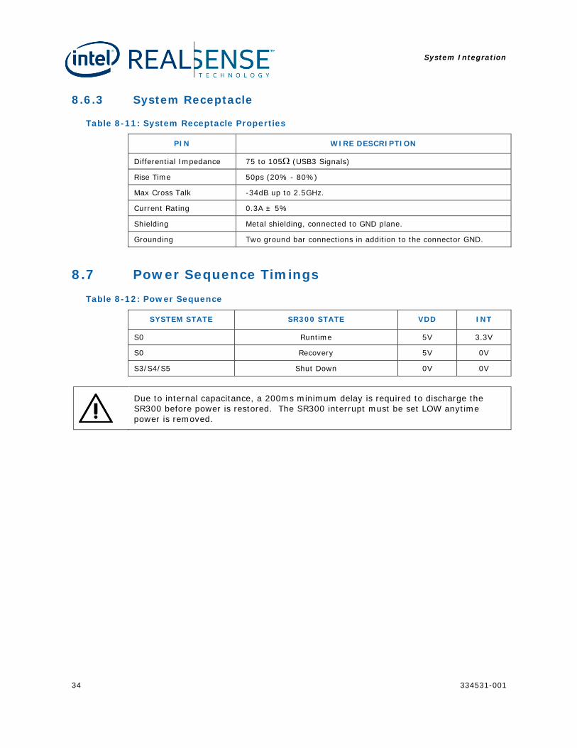
8.6.3 System Receptacle
Table 8-11: System Receptacle Properties
PIN WIRE DESCRIPTION
Differential Impedance 75 to 105Ω (USB3 Signals)
Rise Time 50ps (20% - 80%)
Max Cross Talk -34dB up to 2.5GHz.
Current Rating 0.3A ± 5%
Shielding Metal shielding, connected to GND plane.
Grounding Two ground bar connections in addition to the connector GND.
8.7 Power Sequence Timings
Table 8-12: Power Sequence
SYSTEM STATE SR300 STATE VDD INT
S0 Runtime 5V 3.3V
S0 Recovery 5V 0V
S3/S4/S5 Shut Down 0V 0V
Due to internal capacitance, a 200ms minimum delay is required to discharge the SR300 before power is restored. The SR300 interrupt must be set LOW anytime power is removed.
System Integration
334531-001 35
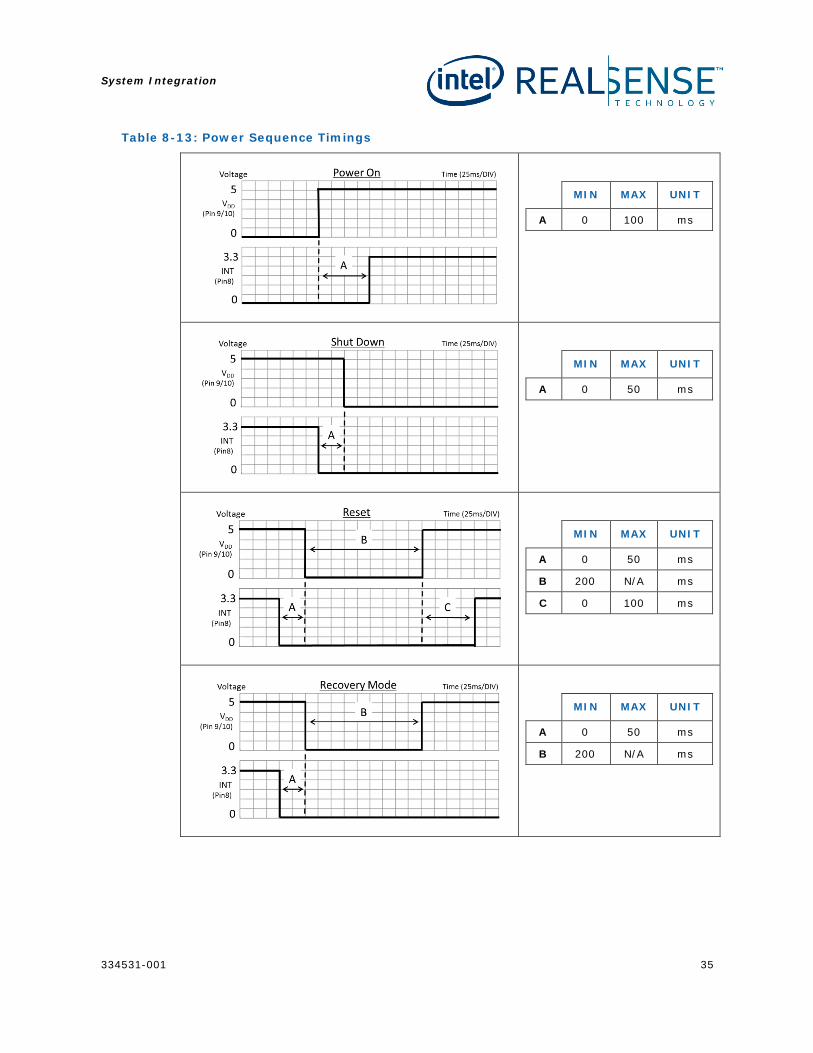
Table 8-13: Power Sequence Timings
MIN MAX UNIT
A 0 100 ms
MIN MAX UNIT
A 0 50 ms
MIN MAX UNIT
A 0 50 ms
B 200 N/A ms
C 0 100 ms
MIN MAX UNIT
A 0 50 ms
B 200 N/A ms
System Integration
36 334531-001
8.8 Acoustics System elements in contact with the SR300 can cause acoustics generated by the SR300 to be transferred and amplified. To minimize this effect, the following considerations are recommended.
• The only chassis contact with the module is the adhesive liner to the adhesive TIM and SR300 alignment holes to the chassis alignment pins.
• Any chassis element around the module (metal/plastic), or any gaskets from the glass/bezel should be spaced at least 50-300um from the module.
• Avoid any hard connection between the camera module assembly frame and the chassis (plastic frame/glass).
• Maintain a minimum air-gap of 50-300um.
Acoustic measurements should be taken with SR300 integrated into the system. Measurements are not intended to be taken with respect to standalone module.
§ §
System BIOS
334531-001 37
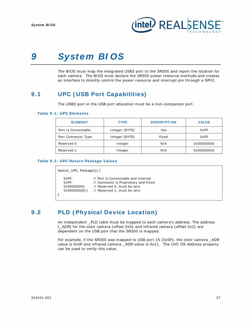
9 System BIOS The BIOS must map the integrated USB3 port to the SR300 and report the location for each camera. The BIOS must declare the SR300 power resource methods and creates an interface to directly control the power resource and interrupt pin through a GPIO.
9.1 UPC (USB Port Capabilities) The USB3 port in the USB port allocation must be a non-companion port.
Table 9-1: UPC Elements
ELEMENT TYPE DESCRIPTION VALUE
Port Is Connectable Integer (BYTE) Yes 0xFF
Port Connector Type Integer (BYTE) Fixed 0xFF
Reserved 0 Integer N/A 0x00000000
Reserved 1 Integer N/A 0x00000000
Table 9-2: UPC Return Package Values
Name(_UPC, Package()) 0xFF, // Port is Connectable and Internal 0xFF, // Connector is Proprietary and Fixed 0x00000000, // Reserved 0, must be zero 0x00000000) // Reserved 1, must be zero
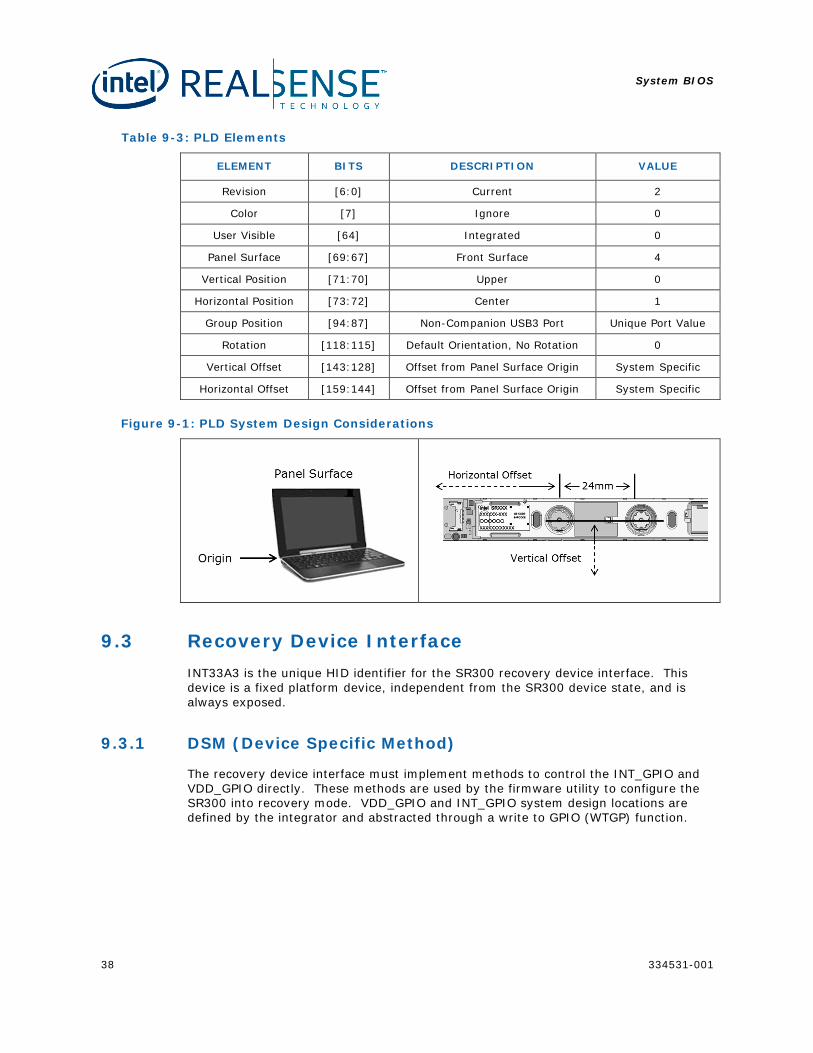
9.2 PLD (Physical Device Location) An independent _PLD table must be mapped to each camera’s address. The address (_ADR) for the color camera (offset 0x0) and infrared camera (offset 0x2) are dependent on the USB port that the SR300 is mapped.
For example, if the SR300 was mapped to USB port 15 (0x0F), the color camera _ADR value is 0x0F and infrared camera _ADR value is 0x11. The UVC OS Address property can be used to verify this value.
System BIOS
38 334531-001
Table 9-3: PLD Elements
ELEMENT BITS DESCRIPTION VALUE
Revision [6:0] Current 2
Color [7] Ignore 0
User Visible [64] Integrated 0
Panel Surface [69:67] Front Surface 4
Vertical Position [71:70] Upper 0
Horizontal Position [73:72] Center 1
Group Position [94:87] Non-Companion USB3 Port Unique Port Value
Rotation [118:115] Default Orientation, No Rotation 0
Vertical Offset [143:128] Offset from Panel Surface Origin System Specific
Horizontal Offset [159:144] Offset from Panel Surface Origin System Specific
Figure 9-1: PLD System Design Considerations
9.3 Recovery Device Interface INT33A3 is the unique HID identifier for the SR300 recovery device interface. This device is a fixed platform device, independent from the SR300 device state, and is always exposed.
9.3.1 DSM (Device Specific Method)
The recovery device interface must implement methods to control the INT_GPIO and VDD_GPIO directly. These methods are used by the firmware utility to configure the SR300 into recovery mode. VDD_GPIO and INT_GPIO system design locations are defined by the integrator and abstracted through a write to GPIO (WTGP) function.
System BIOS
334531-001 39
Table 9-4: Recovery Device Method Arguments
ARGUMENT DESCRIPTION VALUE
Arg0 Unique Function Identifier F5CF0FF7-5D60-4842-82C0-FA1A61D873F2
Arg1 Integer Revision Level 0
Arg2 Integer Function Index 0: QUERY, 1: INT_GPIO, 2: VDD_GPIO
Arg3 Package Parameters 0: Disable, 1: Enable
9.4 Power Resource The BIOS needs to specify the serialized power resource methods for enabling and disabling VDD_GPIO based on the OSPM policies.
Table 9-5: Power Resource Methods
OBJECT DESCRIPTION
_OFF Disable the power resource.
_ON Enable the power resource.
_STA Evaluate enable/disable state of the power resource.
Adding the serialized statement ensure that multiple operations are not attempted concurrently.
§ §

System Assembly and Rework
40 334531-001
10 System Assembly and Rework The system assembly and rework flows are specific to the recommended 3M 8805 and 3M 9882 thermal conductive strip.
10.1 System Assembly The SR300 system assembly flow for the adhesive thermal conductive strip is as follows:
1. Clean the imaging module attachment area and system chassis attachment area with isopropyl alcohol (IPA).
2. Once both attachment areas are dry, release one side of the adhesive strip and place securely on the system chassis attachment area(1). Ensure flush attachment, no wrinkles or bubbles.
3. Release second side of adhesive strip.
4. Attach the SR300 adhesive liner area to the adhesive strip on the system chassis attachment area, use alignment pins as guides. The external force applied to the SR300 assembly frame should not exceed 180N or 20 PSI. Refer to the TIM strip bonding force specification for minimum force requried.
5. Remove the plastic protective liner from the SR300 using the pull tab. Verify no excess charge has accumulated around the components.
(1) Refer to the application pressure guidelines of the adhesive strip to ensure proper “flexible to rigid” surface connection of the imaging module to the system.
Figure 10-1: Plastic Protective Liner
If the plastic protective liner is not removed, this will cause significant impact to SR300 image quality and performance.
System Assembly and Rework
334531-001 41
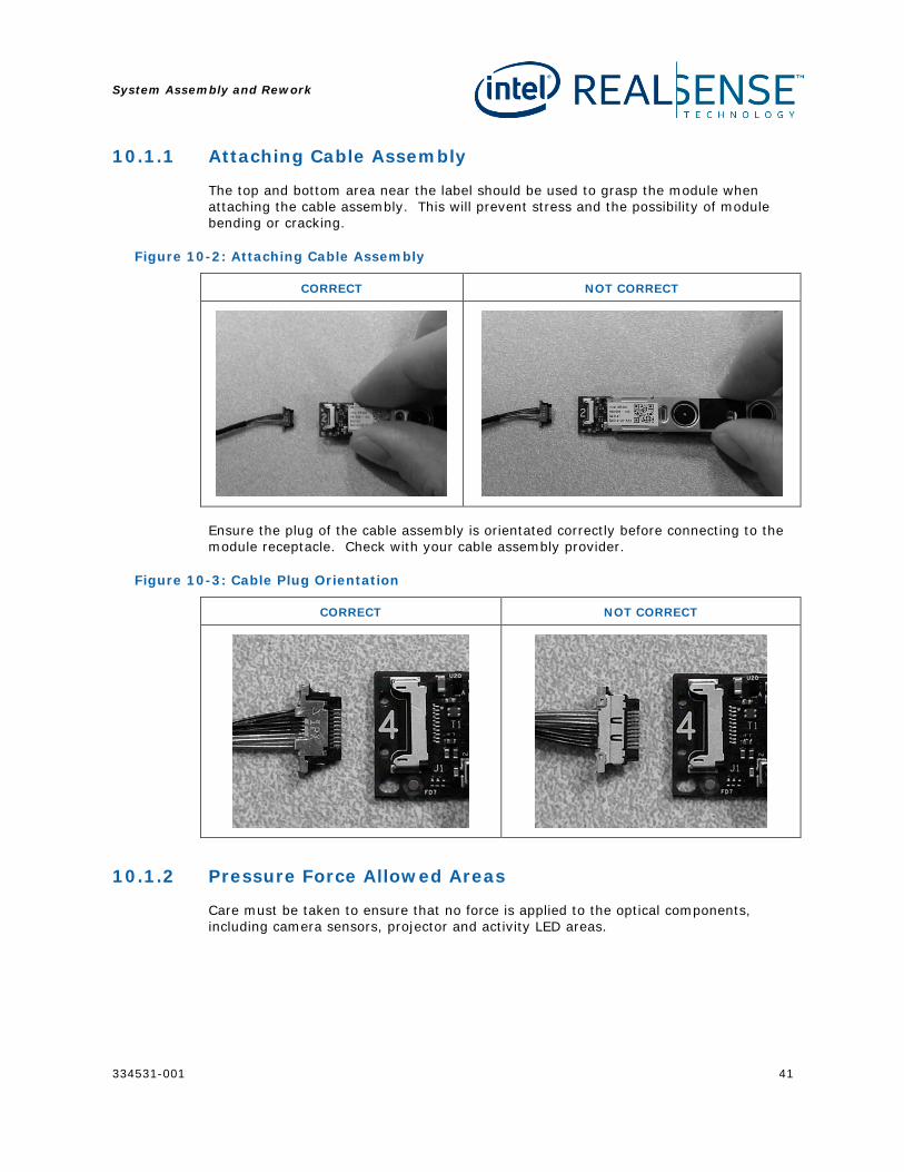
10.1.1 Attaching Cable Assembly
The top and bottom area near the label should be used to grasp the module when attaching the cable assembly. This will prevent stress and the possibility of module bending or cracking.
Figure 10-2: Attaching Cable Assembly
CORRECT NOT CORRECT
Ensure the plug of the cable assembly is orientated correctly before connecting to the module receptacle. Check with your cable assembly provider.
Figure 10-3: Cable Plug Orientation
CORRECT NOT CORRECT
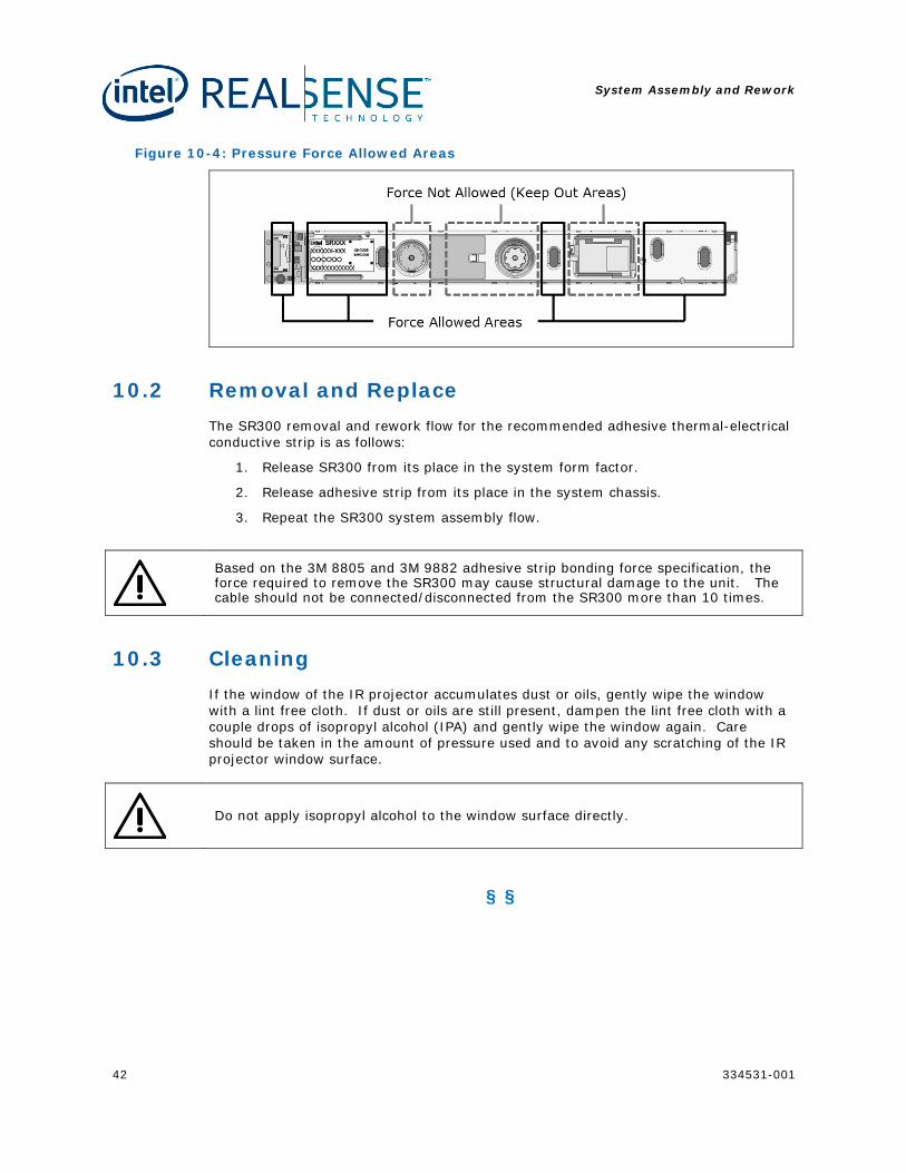
10.1.2 Pressure Force Allowed Areas
Care must be taken to ensure that no force is applied to the optical components, including camera sensors, projector and activity LED areas.
System Assembly and Rework
42 334531-001
Figure 10-4: Pressure Force Allowed Areas
10.2 Removal and Replace The SR300 removal and rework flow for the recommended adhesive thermal-electrical conductive strip is as follows:
1. Release SR300 from its place in the system form factor.
2. Release adhesive strip from its place in the system chassis.
3. Repeat the SR300 system assembly flow.
Based on the 3M 8805 and 3M 9882 adhesive strip bonding force specification, the force required to remove the SR300 may cause structural damage to the unit. The cable should not be connected/disconnected from the SR300 more than 10 times.
10.3 Cleaning If the window of the IR projector accumulates dust or oils, gently wipe the window with a lint free cloth. If dust or oils are still present, dampen the lint free cloth with a couple drops of isopropyl alcohol (IPA) and gently wipe the window again. Care should be taken in the amount of pressure used and to avoid any scratching of the IR projector window surface.
Do not apply isopropyl alcohol to the window surface directly.
§ §
Labeling
334531-001 43
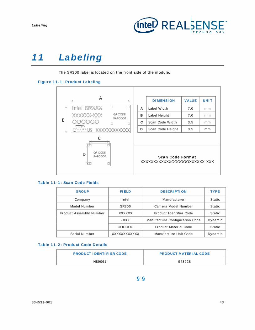
11 Labeling The SR300 label is located on the front side of the module.
Figure 11-1: Product Labeling
DIMENSION VALUE UNIT
A Label Width 7.0 mm
B Label Height 7.0 mm
C Scan Code Width 3.5 mm
D Scan Code Height 3.5 mm
Scan Code Format
XXXXXXXXXXXXOOOOOOXXXXXX-XXX
Table 11-1: Scan Code Fields
GROUP FIELD DESCRIPTION TYPE
Company Intel Manufacturer Static
Model Number SR300 Camera Model Number Static
Product Assembly Number XXXXXX Product Identifier Code Static
-XXX Manufacture Configuration Code Dynamic
OOOOOO Product Material Code Static
Serial Number XXXXXXXXXXXX Manufacture Unit Code Dynamic
Table 11-2: Product Code Details
PRODUCT IDENTIFIER CODE PRODUCT MATERIAL CODE
H89061 943228
§ §
Mechanical Drawing
44 334531-001
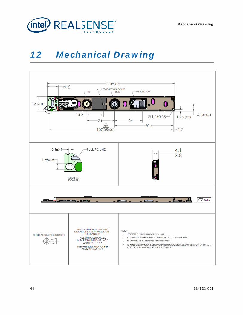
12 Mechanical Drawing
Mechanical Drawing
334531-001 45
Mechanical Drawing
46 334531-001
EXAMPLE 1 THROUGH-HOLE DESIGN
EXAMPLE 2 THROUGH-HOLE DESIGN
§ §
Regulatory Compliance
334531-001 47
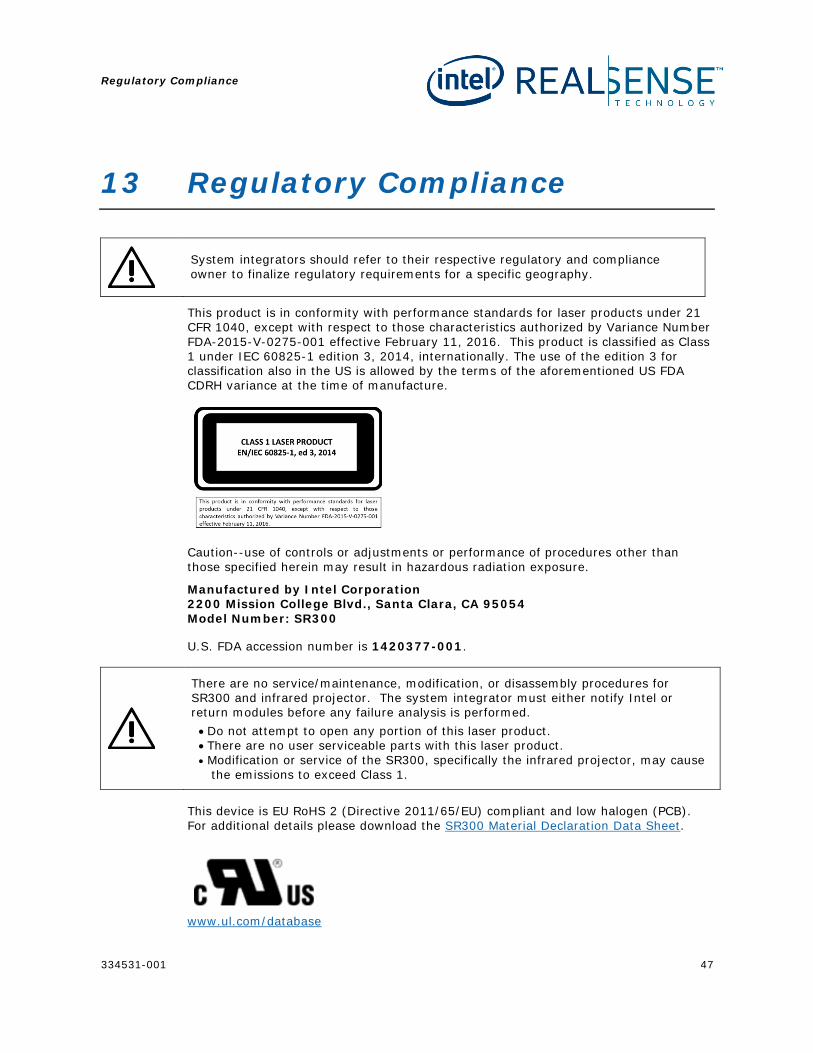
13 Regulatory Compliance
System integrators should refer to their respective regulatory and compliance owner to finalize regulatory requirements for a specific geography.
This product is in conformity with performance standards for laser products under 21 CFR 1040, except with respect to those characteristics authorized by Variance Number FDA-2015-V-0275-001 effective February 11, 2016. This product is classified as Class 1 under IEC 60825-1 edition 3, 2014, internationally. The use of the edition 3 for classification also in the US is allowed by the terms of the aforementioned US FDA CDRH variance at the time of manufacture.
Caution--use of controls or adjustments or performance of procedures other than those specified herein may result in hazardous radiation exposure.
Manufactured by Intel Corporation 2200 Mission College Blvd., Santa Clara, CA 95054 Model Number: SR300
U.S. FDA accession number is 1420377-001.
There are no service/maintenance, modification, or disassembly procedures for SR300 and infrared projector. The system integrator must either notify Intel or return modules before any failure analysis is performed.
• Do not attempt to open any portion of this laser product. • There are no user serviceable parts with this laser product. • Modification or service of the SR300, specifically the infrared projector, may cause
the emissions to exceed Class 1.
This device is EU RoHS 2 (Directive 2011/65/EU) compliant and low halogen (PCB). For additional details please download the SR300 Material Declaration Data Sheet.
www.ul.com/database
Regulatory Compliance
48 334531-001
NWGQ2.E139761 NWGQ8.E139761 The Intel(R) RealSense(TM) Camera / SR300, has passed the USB-IF Test Procedure for USB 3.1 Gen 1 products.
http://www.usb.org/kcompliance/view/ TID: 310000184
§ §
SR300 Cable Drawings
334531-001 49
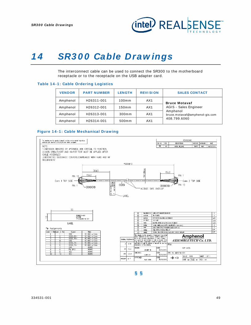
14 SR300 Cable Drawings The interconnect cable can be used to connect the SR300 to the motherboard receptacle or to the receptacle on the USB adapter card.
Table 14-1: Cable Ordering Logistics
VENDOR PART NUMBER LENGTH REVISION SALES CONTACT
Amphenol H26311-001 100mm AX1 Bruce Motavaf AGIS - Sales Engineer Amphenol [email protected] 408.799.6060
Amphenol H26312-001 150mm AX1
Amphenol H26313-001 300mm AX1
Amphenol H26314-001 500mm AX1
Figure 14-1: Cable Mechanical Drawing
§ §
SR300 USB Adapter
50 334531-001
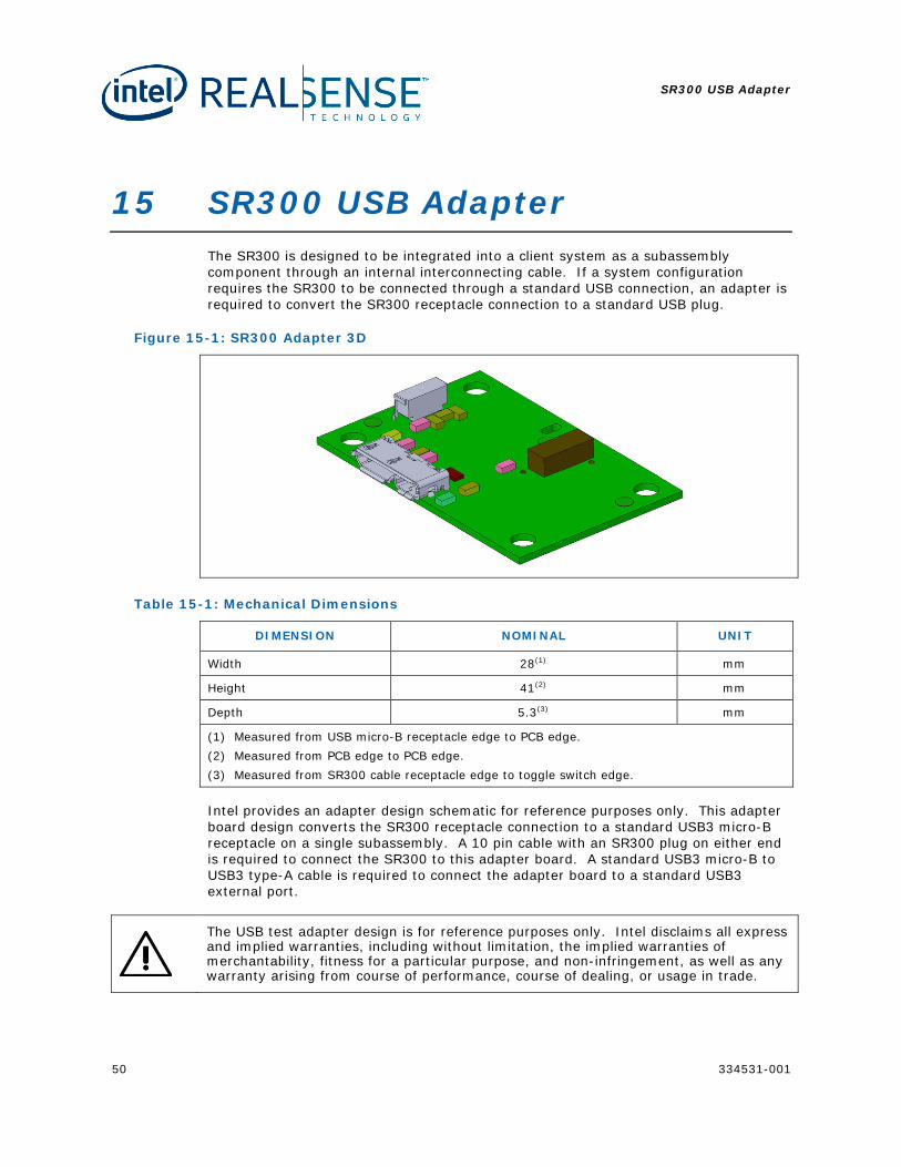
15 SR300 USB Adapter The SR300 is designed to be integrated into a client system as a subassembly component through an internal interconnecting cable. If a system configuration requires the SR300 to be connected through a standard USB connection, an adapter is required to convert the SR300 receptacle connection to a standard USB plug.
Figure 15-1: SR300 Adapter 3D
Table 15-1: Mechanical Dimensions
DIMENSION NOMINAL UNIT
Width 28(1) mm
Height 41(2) mm
Depth 5.3(3) mm
(1) Measured from USB micro-B receptacle edge to PCB edge. (2) Measured from PCB edge to PCB edge. (3) Measured from SR300 cable receptacle edge to toggle switch edge.
Intel provides an adapter design schematic for reference purposes only. This adapter board design converts the SR300 receptacle connection to a standard USB3 micro-B receptacle on a single subassembly. A 10 pin cable with an SR300 plug on either end is required to connect the SR300 to this adapter board. A standard USB3 micro-B to USB3 type-A cable is required to connect the adapter board to a standard USB3 external port.
The USB test adapter design is for reference purposes only. Intel disclaims all express and implied warranties, including without limitation, the implied warranties of merchantability, fitness for a particular purpose, and non-infringement, as well as any warranty arising from course of performance, course of dealing, or usage in trade.
SR300 USB Adapter
334531-001 51
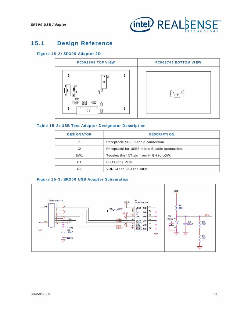
15.1 Design Reference
Figure 15-2: SR300 Adapter 2D
PC002708 TOP VIEW PC002708 BOTTOM VIEW
Table 15-2: USB Test Adapter Designator Description
DESIGNATOR DESCRIPTION
J1 Receptacle SR300 cable connection.
J2 Receptacle for USB3 micro-B cable connection.
SW1 Toggles the INT pin from HIGH to LOW.
D1 ESD Diode Pack
D3 VDD Green LED Indicator
Figure 15-3: SR300 USB Adapter Schematics
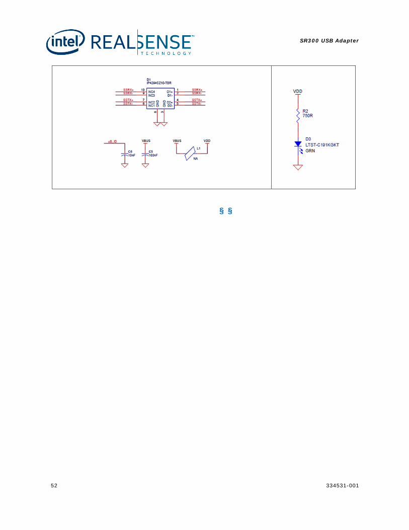
SR300 USB Adapter
52 334531-001
§ §
Schematic Checklist
334531-001 53
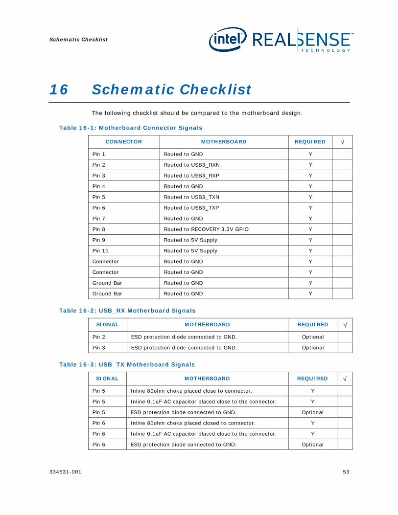
16 Schematic Checklist The following checklist should be compared to the motherboard design.
Table 16-1: Motherboard Connector Signals
CONNECTOR MOTHERBOARD REQUIRED √
Pin 1 Routed to GND Y
Pin 2 Routed to USB3_RXN Y
Pin 3 Routed to USB3_RXP Y
Pin 4 Routed to GND Y
Pin 5 Routed to USB3_TXN Y
Pin 6 Routed to USB3_TXP Y
Pin 7 Routed to GND Y
Pin 8 Routed to RECOVERY 3.3V GPIO Y
Pin 9 Routed to 5V Supply Y
Pin 10 Routed to 5V Supply Y
Connector Routed to GND Y
Connector Routed to GND Y
Ground Bar Routed to GND Y
Ground Bar Routed to GND Y
Table 16-2: USB_RX Motherboard Signals
SIGNAL MOTHERBOARD REQUIRED √
Pin 2 ESD protection diode connected to GND. Optional
Pin 3 ESD protection diode connected to GND. Optional
Table 16-3: USB_TX Motherboard Signals
SIGNAL MOTHERBOARD REQUIRED √
Pin 5 Inline 80ohm choke placed close to connector. Y
Pin 5 Inline 0.1uF AC capacitor placed close to the connector. Y
Pin 5 ESD protection diode connected to GND. Optional
Pin 6 Inline 80ohm choke placed closed to connector. Y
Pin 6 Inline 0.1uF AC capacitor placed close to the connector. Y
Pin 6 ESD protection diode connected to GND. Optional
Schematic Checklist
54 334531-001
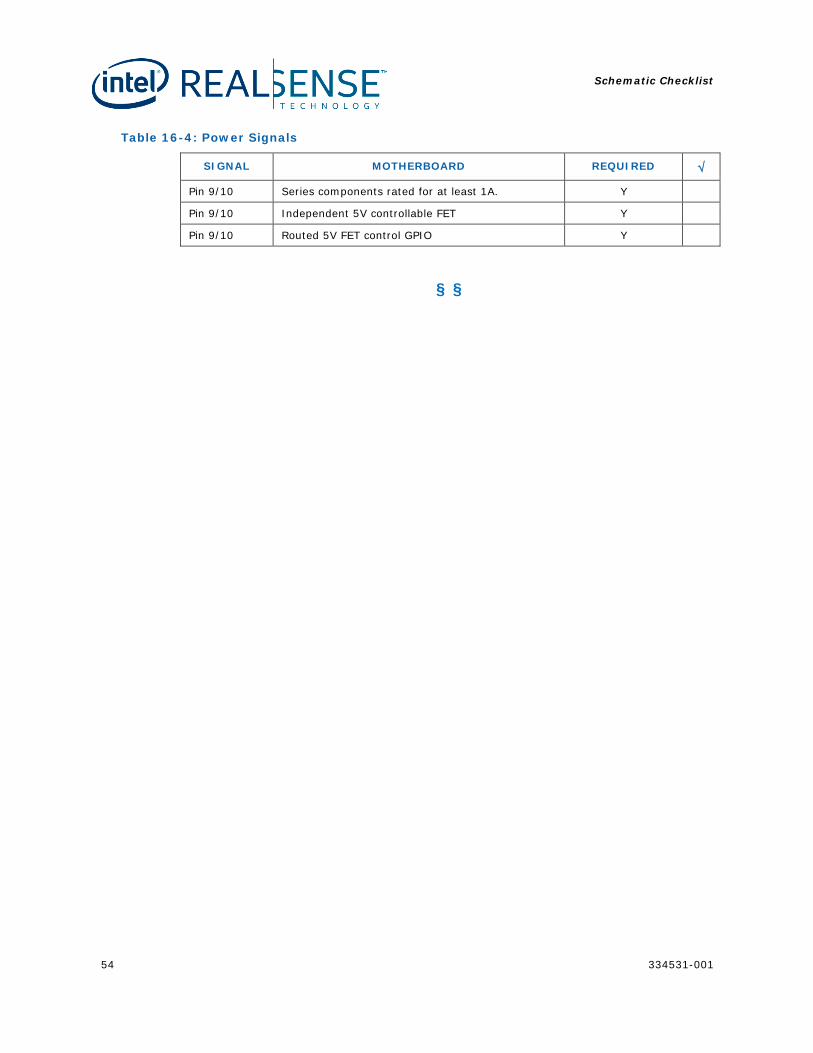
Table 16-4: Power Signals
SIGNAL MOTHERBOARD REQUIRED √
Pin 9/10 Series components rated for at least 1A. Y
Pin 9/10 Independent 5V controllable FET Y
Pin 9/10 Routed 5V FET control GPIO Y
§ §