embedded systems and avionics
TRANSCRIPT

7/29/2019 Embedded Systems and Avionics
http://slidepdf.com/reader/full/embedded-systems-and-avionics 1/58
Internship Report on Embedded Systems(8051)
(Undertaken during Summer Training as a part of 9th
Semester) Submitted to Amity University in partial fulfilment
of the requirements for the award of
B.Tech Aerospace + M.Tech Avionics (Dual) Degree(Session 2009-14)
By
Ana Bhalla, 03
Manish Tripathi, 16
Sadhana Singh, 22
Amity Institute of Space Science and Technology
Amity University (UP)
Noida – 201301
Under the guidance of
Prof. M.S PrasadHOD Amity Institute of Space Science And Technology
Noida-201301 , UP
Candidates Declaration / Certificate

7/29/2019 Embedded Systems and Avionics
http://slidepdf.com/reader/full/embedded-systems-and-avionics 2/58
We hereby declare that the work being presented in this report entitled
“Obstacle Avoidance Robot Using Advanced Microcontroller AT89C51 ” is an
authentic record of our own work carried out under the supervision of Er. Raj
Kumar.-----------
The matter embodied in this report has not been submitted by us for the award
of any other degree.
Dated: 17/07/2013 Name of Students
Department: Embedded System Sadhana Singh,
21 Ana Bhalla,02
Cetpa Infotech Private Limited Noida Manish Tripathi,
Sadhana Singh,216
Manish Tripathi,16
This is to certify that the above statement made by the candidates is correct to
the best of my knowledge.
Miss Medhavi Mr.Raj Kumar
Date: 17/07/2013 Designation:
Department: Embedded System
Date………..

7/29/2019 Embedded Systems and Avionics
http://slidepdf.com/reader/full/embedded-systems-and-avionics 3/58
ACKNOWLEDGEMENT
We express thanks to the individuals who contributed in various ways for the
completion of the project. The successful culmination of our efforts reminds us
of our indebtedness towards our venerated guide “------------” of the
department of Embedded System, CETPA INFOTECH PRIVATE LIMITED
for his valuable guidance and providing encouragement throughout the
semester.
We are also thankful to all the faculty members of the department of Embedded
System, CETPA INFOTECH PRIVATE LIMITED NOIDA for their valuable
suggestions and help provided to us from time to time.
Last but not the least we also express our gratitude towards our respected Prof.M.S.Prasad (HOD-AISST) and our friends and other people who have been
indirectly involved in the successful completion of the project and their valuable
advice in the hour of need, providing the requisite facilities for completion of
the project work.

7/29/2019 Embedded Systems and Avionics
http://slidepdf.com/reader/full/embedded-systems-and-avionics 4/58
Contents
Contents................................................................................................................ 4
Abstract................................................................................................................. 7
............................................................................................................................. 9
Chapter 1 ..........................................................................................................11
1.1 CETPA Introduction....................................................................................11
1.2 CETPA Objectives........................................................................................111.3 CETPA Education.........................................................................................11
1.4 CETPA Research & Development...............................................................11
1.5 CETPA Open Platform.................................................................................12
1.6 CETPA E-Magazine.....................................................................................12
1.7 CETPA Club................................................................................................. 12
........................................................................................................................ 12
1.8 CETPA Seminar...........................................................................................12
Chapter 2 Introduction to Embedded systems...................................................14
2.1 Introduction................................................................................................ 15
2.2 Efficiency parameters.................................................................................16
2.2.1 Technical metrics................................................................................. 16
2.2.2 Economical metrics.............................................................................. 16
2.3 Designing Embedded Systems ..................................................................17
2.4 PERIPHERALS ........................................................................................... 19
2.5 APPLICATION OF EMBEDDED SYSTEM ......................................................20
2.6 Some important concepts ..........................................................................20
2.6.1 Differential Steering System...............................................................20
The 8051 microcontroller..............................................................................23
3.2 The 8051 architecture:...............................................................................24
3.2.1 Important features and applications.....................................................25
3.2.2 Pin Description.....................................................................................26
3.2.3 Memory Organization...........................................................................28
3.2.4 The Instruction Set...............................................................................30
3.2.5 Program Status Word...........................................................................30
3.2.6 Addressing Modes ...............................................................................30

7/29/2019 Embedded Systems and Avionics
http://slidepdf.com/reader/full/embedded-systems-and-avionics 5/58
3.3 Liquid Crystal Display Fundamentals..........................................................31
3.4 THEORY OF D.C. MOTORS...........................................................................32
3.4.1 DC motor types....................................................................................33
Brushed............................................................................................................ 33
Synchronous..................................................................................................... 33
Brushless.......................................................................................................... 33
3.4.2 DC MOTOR SPEED CONTROL---PWM TECHNIQUE................................33
3.4.3 L293D...................................................................................................36
3.4.4 CONCEPT OF H BRIDGE HARDWARE CONTROL OF DC MOTOR.............37
3.5 INFRARED SENSORS (IR SENSORS)[6](refer-6)...........................................39
3.5.1 WORKING OF INFRARED MOTION DETECTOR COMPONENTS ............39
3.5.2 COMPARATOR.......................................................................................41
CHAPTER 4...........................................................................................................43
Obstacle Detector Robot......................................................................................43
4.1 DESIGN AND IMPLEMENTATION..................................................................44
4.3.3 MOTOR CONTROL CIRCUIT USING H BRIDGE...........................................50
4.6 FUTURE SCOPE &APPLICATION...................................................................53
RESULT AND CONCLUSION...............................................................................54
Appendix I : Code for the Obstacle Detector Robot.............................................55
Appendix II Softwares required for the coding.....................................................56
Topview Simulator ...........................................................................................56
ISIS Schematic Capture or Proteus ..................................................................57
REFERENCES........................................................................................................57
Table of figures :
Figure 2-1 Apollo guidance
system…………………………………………………………..14
Figure 2-2 Prototype tofinal……………………………………………………………………………………………16
Figure 2-3 differential steering……………………………………………………………………………………….18Figure 3-1 8051 a) Pin Diagram b)
Architecture……………………………………………………………….22Figure 3-2 Interrupts 0f
89C51…………………………………………………………………………………………26

7/29/2019 Embedded Systems and Avionics
http://slidepdf.com/reader/full/embedded-systems-and-avionics 6/58
Figure 3-3 LCD panel and IC driver locations……………………………………………28
Figure 3-4 Motor speed variation due to continuous on/off……………………………….31
Figure 3-6 pin diagram of L293d…………………………………………………………..32.
Figure 3-7 working of IR Sensors…………………………………………………………..34
Figure 3-8 IR sensor
circuit………………………………………………………………....38
Figure 4-1 block Diagram of Obstacle Detector Robot…………………………………….43
Figure 4-2 Schematic of obstacle detector on Proteus……………………………………..43
Figure 4-3: MICROCONTROLLER INTERFACE WITH L293D TO CONTROL DC MOTOR…….44
Figure 4-4 Sensor Array…………………………………………………………………….44
Figure 4-5 Voltage Regulators………………………………………………………………
45
Figure 1-6 The motor control ……………………………………………………………………….48Figure 4-7 Reflective
Server………………………………………………………………………………………………………….50

7/29/2019 Embedded Systems and Avionics
http://slidepdf.com/reader/full/embedded-systems-and-avionics 7/58
Abstract
Embedded systems and Avionics
The basic aim of we students in joining this course was acquainting
ourselves some knowledge of the industry of electronics mainly related toembedded systems and implement that in our further studies as they play
a very important role in present day aerospace and its related avionics.
Before understanding the role of embedded systems in modern day
avionics we must first understand the terminology. The word Avionics
refers to an airborne electronic equipment. For e.g. the altimeter and its
related subsystems like the Pitot tube tube etc. is one of the on-board
instrument also referred to as avionics .avionics.
An embedded system is a computer system designed for specific control functions within a
larger system, often with real-time computing constraints. It is embedded as part of acomplete device often including hardware and mechanical parts. It can be characterized

7/29/2019 Embedded Systems and Avionics
http://slidepdf.com/reader/full/embedded-systems-and-avionics 8/58
as the combination of hardware and software to perform a specific task. Its further
explanation will be given in chapter 2.
If you find difficulty in visualising what are Embedded Systems, we all
have heard about Robots , about the various machines that are being
adopted in multi-national companies for automization of all theprocesses , about the KIROBO Robot also christened as the Robot
Astronaut of Japan etc. are all some of the systems that are based on this
technology.
In the early days of the aircraft industry most of the calculations and
presumptions related to the aircraft safety, guidance, navigation, and
control were carried out by the pilot itself. Thus the need of automization
of various equipments increased rapidly throughout to reduce the work
load on the pilot. This demand for automization was the cause for the rise
of an entirely new science called the embedded systems in Avionics.
The Apollo Guidance system used for the guidance system of the Apollo
satellite was in fact the first recognizable embedded system developed by
the MIT Instrumentation Laboratory. Embedded systems are a very
important part for missiles, the Inertial Navigation System and the Flight
control systems. These days we can see the embedded systems all
around us in the form of various automation home appliances like The
Washing Machine, Automated cars etc.
In the following report we will be explaining about the company we had
the pleasure of being associated with I.e. CETPA in Chapter 1. This isfollowed by introduction to embedded systems explanations of the various
concepts related to embedded systems in Chapter 2. Chapter 3 deals with
explanation of the various devices we dealt with during our internship and
will also be giving a brief description about the project named: Obstacle
Detector Robot worked on by us in the concluding chapter, Chapter 4 .
Organization
overview

7/29/2019 Embedded Systems and Avionics
http://slidepdf.com/reader/full/embedded-systems-and-avionics 9/58

7/29/2019 Embedded Systems and Avionics
http://slidepdf.com/reader/full/embedded-systems-and-avionics 10/58

7/29/2019 Embedded Systems and Avionics
http://slidepdf.com/reader/full/embedded-systems-and-avionics 11/58
Chapter 1
Organization review
1.1 CETPA Introduction
CETPA Info-Tech Pvt. Ltd. is an ISO 9001:2008 Certified Multinational Organization which
deals in the field of Software Development & Embedded Products Development, Placement
Consultancy and Engineers Training Programs. CETPA Info-Tech has combined unparalleled
experience, comprehensive capabilities and extensive research, to become one of the premier
Training, Development & Consultancy Organization in India and abroad.
The mission of CETPA is to work for the promotion of computer education and technology
in India and abroad. CETPA is a group of professionals who are working for the promotion
of technology. CETPA provides open platform for the development of the various computer software. They are a part of Linux Promotion Organization.
1.2 CETPA Objectives
> Promoting Computer Education & Technology
> Open platform for the development jobs
> Provide World Class Computer Education
> Organize Paper Presentation & Quizzes
> Organize Conferences & Seminars
> Collaboration with other Institute
> Launch Research Paper & Projects of the Members
> Research for Advance Technology
> Honor Outstanding Personalities.
1.3 CETPA Education
CETPA is an association dedicated for spreading advance computer education to all over the
world. CETPA provides computer education in advance technology courses like LINUX,J2EE, VHDL, EMBEDDED SYSTEM, ADVANCE EMBEDDED SYSTEM, CAD , Pro-E
or Mechanical & Electronics students, .NET, MATLAB, ADVANCE JAVA, ORACLE,
SOFTWARE TESTING etc.
1.4 CETPA Research & Development
CETPA is working continuously in Research and Development field from the very
beginning. CETPA has developed a number of advanced software and currently working in
following main projects :
> Congestion Control in Wireless Traffic

7/29/2019 Embedded Systems and Avionics
http://slidepdf.com/reader/full/embedded-systems-and-avionics 12/58
> Real Time Scheduling for Automatic Guided Vehicles
> Advancement in Microprocessors Technology
> CETPA Linux( releasing soon)
>
1.5 CETPA Open Platform
CETPA is an association, which is providing open platform for software development. Their
thinkingTheir thinking is that development tools should be provided free of cost so that the
technological advancement and refinement can take place unhindered. In this mission everyone is
invited .CETPA Linux is a special flavor of Linux that can be easily optimized and customized for
just about any application or need Extreme performance, configurability and a top-notch user and
developer community are all hallmarks of the CETPA experience.
1.6 CETPA E-Magazine
CETPA e-magazine is the best way to give new comers a chance to show their ability
.Through e-magazines our student members can give their articles, projects, & thoughts to
CETPA. These magazines not only have ideas of new comers but also thesis of well-known
scientists, professionals and professors.
1.7 CETPA Club
CETPA has two types of clubs for professionals and students. Members of the professional club
are professionals from various domains who are working seriously for the fulfillment of CETPA
objectives. The members of the students Club are the students who are provided platform by CETPA
to present their research papers, and to share their views with other members of the club. Projects
submitted by the students are sponsored in the national and international seminars for paper
presentation and publishing.
1.8 CETPA Seminar
CETPA conducts free of cost seminars on various technologies in different institutions and
organizations to help students and professionals to acquaint themselves with the latest
technological advancements. Their vision serves as the framework for their Roadmap and guides
every aspect of the business by describing what they need to accomplish in order to continue
achieving sustainable and quality growth.
> People: Be a great place to work where people are inspired to be the best they can be.
> Portfolio: Bring to the world a portfolio of quality education with placement
assistance and be the pioneer in the field of development
> Partners: Nurture a winning network of customers and Clients, together we createmutual and long lasting value.

7/29/2019 Embedded Systems and Avionics
http://slidepdf.com/reader/full/embedded-systems-and-avionics 13/58
> Profit: Maximize long-term return while being mindful of our overall
responsibilities.
> Productivity: Be a highly effective, lean and fast-moving organization.
> Qualities: Inspire creativity, passion, optimism and fun.

7/29/2019 Embedded Systems and Avionics
http://slidepdf.com/reader/full/embedded-systems-and-avionics 14/58
Chapter 2
Chapter 2 Introduction to Embedded systems
Introduction to
embedded
systems

7/29/2019 Embedded Systems and Avionics
http://slidepdf.com/reader/full/embedded-systems-and-avionics 15/58
2.1 Introduction
An embedded system is a computer system designed for specific control functions
within a larger system, often with real-time computing constraints. It is embedded as
part of a complete device often including hardware and mechanical parts. By
contrast, a general-purpose computer, such as a personal computer (PC), is designed to be
flexible and to meet a wide range of end-user needs. Embedded systems control many
devices in common use today.
Embedded Systems are computing systems with tightly coupled software &
hardware integration that are designed to perform a dedicated task or functions
Embedded systems are computers which are part of special-purpose devices. Due to the
limited duties this systems can be highly optimized to the particular needs. Traditionallymost of this systems are used for control and process measurement, as a side-effect of
higher integration of integrated circuits more complex applications can be solved by
embedded systems. To be able to solve this problems embedded systems are commonlyequipped
with various kinds of peripherals.
As already stated in the preceding chapter the earliest applications of these included the
guidance computer of the Minuteman I missiles and the Apollo guidance computer. TheMinuteman I & II missiles were intercontinental ballistic nuclear warheads, produced by
Boeing in the 1960’s.

7/29/2019 Embedded Systems and Avionics
http://slidepdf.com/reader/full/embedded-systems-and-avionics 16/58
Figure 2-1 Apollo guidance system
Figure 2-0-2: Apollo guidance system
Nowadays embedded systems can be found in devices from digital watches to traffic-control systems. The broad range of applications with totally different requirements lead
to various implementation approaches. The range of hardware used in embedded systemsreaches from FPGAs to full blown desktop CPUs which are accompanied by special
purpose ICs such as DSPs. On the software side, depending on the needs, everything,from logic fully implemented in hardware to systems with own operating system and
different applications running on it, can be found.
2.2 Efficiency parameters
There are certain hardware independent parameters which are used to compare the
various embedded systems archictecturesarchitectures like Atmel, Arm etc. these are
divided into Technical and economical parameters or metrics.
2.2.1 Technical metricsThese are used to compare the technical designs and specifications of the particular
embedded system and thus using the one which would comply with the desired technical
requirements
Performance describes the execution time or throughput of the system.
Energy Efficiency is an indicator for the amount of power consumed by the device.
Size as a metric is used if there are constraints for physical size (eg:minimal sizerequirement for satellite systems)
Flexibility is a metric for ease of reconfiguration and reusability.
2.2.2 Economical metricsThese metrics are used for comparing the cost aspect of using a particular embedded
system for designing the particular system some of them are :
Unit Cost describes the net cost for manufacturing a single unit of the particular system based on the availability and the technological machinery required for its manufacturing.
Flexibility in a economical sense describes the ability to change the functionality of the
system without incurring heavy cost.

7/29/2019 Embedded Systems and Avionics
http://slidepdf.com/reader/full/embedded-systems-and-avionics 17/58
Time to Market indicates the amount of time to develop a system to the point that it can
be released for usage for the particular requirement (like sale or testing)
After analysing the above said parameters of the different systems based on our task
requirement we choose our controller in a way so as to optimize the technical and
economical metrics.
2.3 Designing Embedded Systems
The following offers a brief step-by-step approach to follow while designing anembedded system:
1. Proposal: An innovative idea or system that makes life easier and/or reduces the
amount of human effort required to complete a task.
2. Definition: Next, the whole system needs to be designed, including what it will do
under all possible sets of input conditions. This definition is perhaps the most critical part, as any error here will affect the working of whole system.
I. I/O Considerations: Defines that for a particular input, what the output of the
system will be, considering the system as a black box.
II. Mathematical Modelling: Design the algorithm for the system to work as desired.
III. Functional Modelling: Design the functions of the system which will accept input
and produce the desired output.
3. Technology Selection: Based on the above points, designers then review the available
technology and select which devices will fulfil all the requirements while balancing
efficiency, cost, and time-to-market and the remaining above mentioned metrics.
4. Integration & PCB design: List all the components, which you need to implement
your functions and design their placement on the PCB. Traces and all other paths must
have the least possible electromagnetic interference (EMI) and should be free from
various errors. While designing the PCB, special attention must be given to the groundas well as all the components on the PCB that use ground.
5. Firmware Development & Debugging: Since hardware needs instructions to execute
the way we want, we need to write the code for every component used by thehardware. This is exactly what is done by the firmware i.e. the application code.
Firmware should be of minimum complexity. Moreover, as we write the code, we face
many errors or bugs and for this we need a proper debugging protocol.

7/29/2019 Embedded Systems and Avionics
http://slidepdf.com/reader/full/embedded-systems-and-avionics 18/58
6. Testing: Debugging tests the piece of code but in testing we test the whole system i.e.
hardware as well as the software that drives that hardware.
7. Documentation: Anyone who accesses your complete application should never ask
you “what does this mean?” or “How does this thing work?” and for this we need to
document everything
Hardware &
SoftwareFinal

7/29/2019 Embedded Systems and Avionics
http://slidepdf.com/reader/full/embedded-systems-and-avionics 19/58
Figure 2-2 Prototype to final
Figure 2-3 Prototype to final
After going through the designing process and its various steps we should get a brief knowledge of the various peripherals that are used for the communication between the
real world and the logical world.
2.4 PERIPHERALS
Embedded Systems talk with the outside world via peripherals, such as:
Serial Communication Interfaces (SCI): RS-232, RS-422, RS-485 etc.
Synchronous Serial Communication Interface: I2C, SPI, SSC and ESSI
(Enhanced Synchronous Serial Interface)
Universal Serial Bus (USB)
Fieldbuses: CAN-Bus, LIN-Bus, PROFIBUS, etc.
Timers: Time Processing Units
Discrete IO: aka General Purpose Input/ Output (GPIO)
Final

7/29/2019 Embedded Systems and Avionics
http://slidepdf.com/reader/full/embedded-systems-and-avionics 20/58
2.5 APPLICATION OF EMBEDDED SYSTEM
Embedded systems span all aspects of modern life and there are many examples of their
use:-
Telecommunications systems employ numerous embedded systems
from telephone switches for the network to mobile phones at the end-user. Computer networking user dedicated routers and network bridges to route data.
Consumer electronics include personal digital assistants (PDAs), mp3 players,
mobile phones, videogame consoles, digital cameras, DVD
players, GPS receivers, and printers. Many household appliances, such
as microwave ovens, washing machines and dishwashers, are including embedded
systems to provide flexibility, efficiency and features. Advanced HVAC systems
use networked thermostats to more accurately and efficiently control temperature
that can change by time of day and season. Home automation uses wired- and
wireless-networking that can be used to control lights, climate, security,
audio/visual, surveillance, etc., all of which use embedded devices for sensing andcontrolling.
Transportation systems from flight to automobiles increasingly use embedded
systems. New airplanes contain advanced avionics such as inertial guidance
systems and GPS receivers that also have considerable safety requirements.
Various electric motors — brushless DC motors, induction motors and DC
motors — are using electric/electronic motor controllers. Automobiles, electric
vehicles, and hybrid vehicles are increasingly using embedded systems to
maximize efficiency and reduce pollution
Medical equipment is continuing to advance with more embedded systemsfor vital signals monitoring, electronic stethoscopes for amplifying sounds, and
various medical imaging(PET, SPECT, CT, MRI) for non-invasive internal
inspections.
Embedded systems are especially suited for use in transportation, fire safety,
safety and security, medical applications and life critical systems as these systems
can be isolated from hacking and thus be more reliable. For fire safety, the
systems can be designed to have greater ability to handle higher temperatures and
continue to operate. In dealing with security, the embedded systems can be self-
sufficient and be able to deal with cut electrical and communication systems.
2.6 Some important concepts
2.6.1 Differential Steering System
During our internship we came to know the importance of motors (DC motors, Stepper
Motor etc.) and their applications whether it be in the form of robots and its locomotive
motion or the usage of them in various control systems like those used in factories. Thus

7/29/2019 Embedded Systems and Avionics
http://slidepdf.com/reader/full/embedded-systems-and-avionics 21/58
in order to understand its programming we would like to first acquaint ourselves with
the locomotive motion of our Robot (as mentioned in the preceding lessons ) which
would be explained in Chapter 4.
The differential steering system features two wheels mounted on a single axis which areindependently powered and controlled, thus providing both drive and steering. Additional
passive wheels (usually casters) are provided for support. If both drive wheels turn in
tandem, the robot moves in a straight line. If one wheel turns faster than the other, therobot follows a curved path. If the wheels turn at equal speed, but in opposite directions,
the robot pivots.
Figure 2-3 differential steering
Figure 2-4 Differential steering
where given the displacement for the left and right wheels respectively, r is the turn
radius for the inner (left) wheel, b is the distance between wheels (from centre-to-centrealong the length of the axle), and Ө is the angle of the turn in radians , vl is the speed at
the centre point on the main axle. In this discussion, we will treat the axle's centre point
as the origin of the simulated robot's frame of reference.
Once we've established the simple geometry for the differential steering system, it is easy
to develop algorithms for controlling the robot's path. Note, though, that we did make animportant simplifying assumption: the wheels maintain a steady velocity. We neglected
the effects of acceleration. If the wheels are allowed to accelerate, the curve which
describes the robot's trajectory can become much more complicated. When working with
very light robots, where the mass (and inertia) of the platform is small, we can often getaway with treating changes in speed as nearly instantaneous. The path that the robot
follows will not be truly circular, but it will be close enough for many applications. For
larger and heavier robots, of course mass is important and acceleration must beconsidered.

7/29/2019 Embedded Systems and Avionics
http://slidepdf.com/reader/full/embedded-systems-and-avionics 22/58
If the right wheel is moving at a velocity of VR and the left wheel at a velocity of VL,
then the following equation can be derived.
Where a positiveθimplies counter-clockwise rotation; the above equation clearly shows
that the angle of the turn can be increased by either,• Increasing the difference in the wheel’s velocities (VR – VL), or
• Keep the wheels at the different velocity for a longer time (t)
All this while b remains constant; in the line following robot, both these parameters are
dynamically changed by the sensors in order to keep the robot away from obstacles.
With the help of these sensors and the H-bridge Circuitry (which we will learn about inChapter 3) we can control the speed and direction of movement of our Robot.

7/29/2019 Embedded Systems and Avionics
http://slidepdf.com/reader/full/embedded-systems-and-avionics 23/58
Chapter 3
The 8051 microcontroller
A microcontroller is an economical computer-on-a-chip built for dealing with specific
tasks, such as displaying or receiving information through LEDs or remote controlled
devices. The most commonly used set of microcontrollers belong to 8051 Family, Pic ,Arm(32 bit) etc. 8051 Microcontrollers continue to remain a preferred choice for a vast
community of hobbyists and professionals. Through 8051, the world became witness to
the most revolutionary set of microcontrollers.Intel fabricated the original 8051 which is known as MCS-51. The other two members of
the 8051 family are:

7/29/2019 Embedded Systems and Avionics
http://slidepdf.com/reader/full/embedded-systems-and-avionics 24/58
i. 8052 – This microcontroller has 256 bytes of RAM and 3 timers. In addition to the
standard features of 8051, this microcontroller has an added 128 bytes of RAM and timer.
It has 8K bytes of on chip program ROM. The programs written for projects using 8051microcontroller can be used to run on the projects using 8052 microcontroller as 8051 is a
subset of 8052.
ii. 8031 – This microcontroller has all the features of 8051 except for it to be ROM-
less. An external ROM that can be as large as 64 K bytes should be programmed and
added to this chip for execution. The disadvantage of adding external ROM is that 2 ports(out of the 4 ports) are used. Hence, only 2 ports are left for I/O operations which can
also be added externally if required for execution.
Comparison of 8051 family members:
Features 8051 8052 8031
RAM(bytes) 128 256 128
ROM 4K 8K 0K
Timers 2 3 2
Serial port 1 1 1
I/O pins 32 32 32
Interrupt sources 6 8 6
Table 13-1 Comparison of the different 8051 microcontrollers
3.1 AT89C51 from Atmel Corporation – Atmel fabricated the flash ROM version of
8051 which is popularly known as AT89C51. The AT89C51 is a low-power, high-
performance CMOS 8-bit microcomputer with 4K bytes of Flash programmable anderasable read only memory (PEROM).The flash memory can erase the contents within
seconds which is best for fast growth. Therefore, 8751 is replaced by AT89C51 to
eradicate the waiting time required to erase the contents and hence expedite the
development time. To build up a microcontroller based system using AT89C51, it is
essential to have ROM burner that supports flash memory. Note that in Flash memory,
entire contents must be erased to program it again. The contents are erased by the ROM
burner. Atmel is working on a newer version of AT89C51 that can be programmed using
the serial COM port of IBM PC in order to get rid of the ROM burner. This is the
controller we will be using our project.
The Atmel AT89C51 is a powerful microcomputer which provides a highly-flexible andcost-effective solution to many embedded control applications.
3.2 The 8051 architecture:
This was designed by the Intel Company in the 1960s .The various members of thisfamily have the same architecture so as to be more user friendly. They differ from each
other in the way they store memory and the memory sizes.

7/29/2019 Embedded Systems and Avionics
http://slidepdf.com/reader/full/embedded-systems-and-avionics 25/58
The first digit of the numbering tells us that it is a 8-bit processor, the second digit tells us
in what way the controller can be reprogrammed, like 0 tells us that it cannot be
reprogrammed. Whereas the third digit corresponds to the number interrupts present inthe device (internal/external). The fourth digit tells us that serial communication is
possible with the 8051.
Figure 3-1 8051 a) Pin Diagram b) Architecture
3.2.1 Important features and applications
•
It provides many functions (CPU, RAM, ROM, I/O, interrupt logic, timer , etc.) ina single package
• 8-bit ALU, Accumulator and Registers; hence it is an 8-bit microcontroller
• 8-bit data bus - It can access 8 bits of data in one operation
• 16-bit address bus - It can access 216 memory locations - 64 kB (65536 locations)
each of RAM and ROM
• On-chip RAM - 128 bytes ("Data Memory")
• On-chip ROM - 4 kB ("Program Memory")
•
Four byte bi-directional input/output port• UART (serial port)
• Two 16-bit Counter/timer s
• Two-level interrupt priority
• Power saving mode

7/29/2019 Embedded Systems and Avionics
http://slidepdf.com/reader/full/embedded-systems-and-avionics 26/58
3.2.2 Pin Description
Pins 1-8: Port 1 Each of these pins can be configured as an input or an output.
Pin 9: RS A logic one on this pin disables the microcontroller and clears the contents of
most registers. In other words, the positive voltage on this pin resets the microcontroller.
By applying logic zero to this pin, the program starts execution from the beginning.
Pins10-17: Port 3 Similar to port 1, each of these pins can serve as general input or
output. Besides, all of them have alternative functions:
Pin 10: RXD Serial asynchronous communication input or Serial synchronous
communication output.
Pin 11: TXD Serial asynchronous communication output or Serial synchronous
communication clock output.
Pin 12: INT0 Interrupt 0 input.
Pin 13: INT1 Interrupt 1 input.
Pin 14: T0 Counter 0 clock input.
Pin 15: T1 Counter 1 clock input.
Pin 16: WR Write to external (additional) RAM.
Pin 17: RD Read from external RAM.
Pin 18, 19: X2, X1 Internal oscillator input and output. A quartz crystal which specifies
operating frequency is usually connected to these pins. Instead of it, miniature ceramics
resonators can also be used for frequency stability. Later versions of microcontrollers
operate at a frequency of 0 Hz up to over 50 Hz.
Pin 20: GND Ground.
Pin 21-28: Port 2 If there is no intention to use external memory then these port pins are
configured as general inputs/outputs. In case external memory is used, the higher address
byte, i.e. addresses A8-A15 will appear on this port. Even though memory with capacity

7/29/2019 Embedded Systems and Avionics
http://slidepdf.com/reader/full/embedded-systems-and-avionics 27/58
of 64Kb is not used, which means that not all eight port bits are used for its addressing,
the rest of them are not available as inputs/outputs.
Pin 29: PSEN If external ROM is used for storing program then a logic zero (0) appears
on it every time the microcontroller reads a byte from memory.
Pin 30: ALE Prior to reading from external memory, the microcontroller puts the lower
address byte (A0-A7) on P0 and activates the ALE output. After receiving signal from
0the ALE pin, the external register (usually 74HCT373 or 74HCT375 add-on chip)
memorizes the state of P0 and uses it as a memory chip address. Immediately after that,
the ALU pin is returned its previous logic state and P0 is now used as a Data Bus. As
seen, port data multiplexing is performed by means of only one additional (and cheap)
integrated circuit. In other words, this port is used for both data and address transmission.
Pin 31: EA By applying logic zero to this pin, P2 and P3 are used for data and addresstransmission with no regard to whether there is internal memory or not. It means that
even there is a program written to the microcontroller, it will not be executed. Instead, the
program written to external ROM will be executed. By applying logic one to the EA pin,
the microcontroller will use both memories, first internal then external (if exists).
Pin 32-39: Port 0 Similar to P2, if external memory is not used, these pins can be used
as general inputs/outputs. Otherwise, P0 is configured as address output (A0-A7) when
the ALE pin is driven high (1) or as data output (Data Bus) when the ALE pin is driven
low (0).
Pin 40: VCC +5V power supply

7/29/2019 Embedded Systems and Avionics
http://slidepdf.com/reader/full/embedded-systems-and-avionics 28/58
Table 3-2 Port 3 description
• XTAL1
Input to the inverting oscillator amplifier and input to the internal clock operating
circuit.
• XTAL2
Output from the inverting oscillator amplifier.
• Oscillator Characters:
XTAL1 and XTAL2 are the input and output, respectively, of an inverting
amplifier which can be configured for use as an on-chip oscillator, as shown in
Figure 1. Either a quartz crystal or ceramic resonator may be used. To drive the
device from an external clock source, XTAL2 should be left unconnected while
XTAL1 is driven as shown in Figure 2. There are no requirements on the duty
cycle of the external clock signal, since the input to the internal clocking circuitry
is through a divide-by-two flip-flop, but minimum and maximum voltage high
and low time specifications must be observed.
3.2.3 Memory Organization
All Atmel Flash microcontrollers have separate address spaces for program and data
memory. The logical separation of program and data memory allows the data memory to
be accessed by 8-bit addresses, which can be more quickly stored and manipulated by an
8- bit CPU.
)a Program Memory

7/29/2019 Embedded Systems and Avionics
http://slidepdf.com/reader/full/embedded-systems-and-avionics 29/58
After reset, the CPU begins execution from location 0000H. Each interrupt is assigned a
fixed location in program memory. The interrupt causes the CPU to jump to that location,
where it executes the service routine. External Interrupt 0, for example, is assigned to
location 0003H. If External Interrupt 0 is used, its service routine must begin at location
0003H. If the interrupt is not used, its service location is available as general purpose
program memory. The interrupt service locations are spaced at 8-byte intervals:
0003H for External Interrupt 0, 000BH for Timer 0,
0013H for External Interrupt 1, 001BH for Timer 1, and so on.
Figure 3-2 Interrupts 0f 89C51
If an interrupt service routine is short enough (as is often the case in control applications),
it can reside entirely within that 8-byte interval. Longer service routines can use a jump
instruction to skip over subsequent interrupt locations.
)b Data Memory
)c
Internal data memory addresses are always 1 byte wide, which implies an address space
of only 256 bytes. However, the addressing modes for internal RAM can in fact
accommodate 384 bytes. Direct addresses higher than 7FH access one memory space,
and indirect addresses higher than 7FH access a different memory space. Thus, the Upper
128 and SFR space occupying the same block of addresses, 80H through FFH, although
they are physically separate entities. The lowest 32 bytes are grouped into 4 banks of 8
registers. Program instructions call out these registers as R0 through R7. Two bits in the
Program Status Word (PSW) select which register bank is in use. This architecture allows
more efficient use of code space, since register instructions are shorter than instructions
that use direct addressing.
For using external memory feature refer to reference no 2.
7/29/2019 Embedded Systems and Avionics
http://slidepdf.com/reader/full/embedded-systems-and-avionics 30/58
3.2.4 The Instruction Set
All members of the Atmel microcontroller family execute the same instruction set. This
instruction set is optimized for 8- bit control applications and it provides a variety of fast
addressing modes for accessing the internal RAM to facilitate byte operations on small
data structures. The instruction set provides extensive support for 1-bit variables as a
separate data type, allowing direct bit manipulation in control and logic systems thatrequire Boolean processing. The following overview of the instruction set gives a brief
description of how certain instructions can be used.
3.2.5 Program Status Word
The Program Status Word (PSW) contains status bits that reflect the current state of the
CPU. The PSW, shown in Figure 11, resides in SFR space. The PSW contains the Carry
bit, the Auxiliary Carry (for BCD operations), the tworegister bank select bits, the
Overflow flag, a Parity bit, and two user-definable status flags. The Carry bit, in addition
to serving as a Carry bit in arithmetic operations, also serves as the “Accumulator” for a
number of Boolean operations.
The bits RS0 and RS1 select one of the four register banks shown in Figure 8. A number
of instructions refer to these RAM locations as R0 through R7. The status of the RS0 and
RS1 bits at execution time determines which of the four banks is selected. The Parity bit
reflects the number of 1s in the Accumulator: P=1 if the Accumulator contains an odd
number of 1s, and P=0 if the Accumulator contains an even number of 1s. Thus, the
number of 1s in the Accumulator plus P is always even. Two bits in the PSW are
uncommitted and can be used as general purpose status flags.
3.2.6 Addressing Modes
The addressing modes in the Flash microcontroller instruction set are as follows.
a) Direct Addressing
In direct addressing, the operand is specified by an 8-bit address field in the instruction.
Only internal data RAM and SFRs can be directly addressed.
b) Indirect Addressing
In indirect addressing, the instruction specifies a register that contains the address of the
operand. Both internal and external RAM can be indirectly addressed. The address
register for 8-bit addresses can be either the Stack Pointer or R0 or R1 of the selected
register bank. The address register for 16-bit addresses can be only the 16-bit data pointer
register, DPTR.
Register Instructions
The register banks, which contain registers R0 through R7, can be accessed by
instructions whose opcodes carry a 3- bit register specification0. Instructions that access
the registers this way make efficient use of code, since this mode eliminates an address
7/29/2019 Embedded Systems and Avionics
http://slidepdf.com/reader/full/embedded-systems-and-avionics 31/58
byte. When the instruction is executed, one of the eight registers in the selected bank is
accessed. One of four banks is selected at execution time by the two bank select bits in
the PSW.
c) Indexed Addressing
Program memory can only be accessed via indexed addressing. This addressing mode isintended for reading look-up tables in program memory. A 16-bit base register (either
DPTR or the Program Counter) points to the base of the table, and the Accumulator is set
up with the table entry number. The address of the table entry in program memory is
formed by adding the Accumulator data to the base pointer.
3.3 Liquid Crystal Display Fundamentals
• A general discussion of how liquid crystal displays work.
• A basic introduction to the chemistry, structure, and properties of liquid crystals
used in displays.
• An overview of display structure, assembly, and related technology is
summarized.
Liquid Crystal Displays (LCDs) are categorized as non-emissive display devices, in that
respect, they do not produce any form of light like a Cathode Ray Tube (CRT). LCDs
either pass or block light that is reflected from an external light source or provided by a
back/side lighting system. There are two modes of operation for LCDs during the absence
of an electric field (applied Power); a mode describes the transmittance state of the liquid
crystal elements. Normal White mode: the display is white or clear and allows light to pass through and Normal Black Mode: the display is dark and all light is diffused.
Virtually all displays in production for PC/Workstation use are normal white mode to
optimize contrast and speed.
A simplified description of how a dot matrix LCD display works is as follows: A twisted
nematic (TN) LC display consists of two polarizers, two pieces of glass, some form of
switching element or electrode to define pixels, and driver Integrated Circuits (ICs) to
address the rows and columns of pixels. To define a pixel (or subpixelsub pixel element
for a colorcolour display), a rectangle is constructed out of Indium Tin Oxide -- a semi-transparent metal oxide (ITO) and charge is applied to this area in order to change the
orientation of the LC material ( change from a white pixel to a dark pixel). The method
utilized to form a pixel in passive and active matrix displays differs and will be described
in later sections. Figure 1 illustrates a cross sectional view of a simple TN LC display.
Figure 2 depicts a dot matrix display as viewed without its metal module/case exposing
the IC drivers.

7/29/2019 Embedded Systems and Avionics
http://slidepdf.com/reader/full/embedded-systems-and-avionics 32/58
Looking directly at the display the gate or row drivers are located either on the left or the
right side of the display while the data or column drivers are located on the top (and or
bottom) of the display. New thin display module technology mounts the ICs on
conductive tape that allows them to be folded behind the display further reducing the size
of the finished module. An IC will address a number of rows or columns.
Figure 1: Cross Section of a Simple LC Display
viewer
///////////////////////////////////// Polarizer _____________________________________ glass
~~~~~~~~~~~~~~~~~~~~~~~~~~~~~~~~~~~~~ Liquid Crystal
_____________________________________ glass\\\\\\\\\\\\\\\\\\\\\\\\\\\\\\\\\\\\\ Polarizer
Backlight
Figure 3-3 LCD panel and IC driver locations
Polarizers are an integral part of a LCD display, possessing the unique property of only
passing light if it is oriented in a specific (oriented) direction. To utilize this phenomena
in TN LC displays, the bottom polarizer orients incoming light in one direction. The
oriented light passes through the LC material and is either unaltered or "bent" 90 degrees.
Depending on the orientation of the top polarizer, this light will either pass through or bediffused. If the light is diffused, it will appear as a dark area. Figure 3 is a simple
illustration of the sequence of events that occur when light passes through a simple
twisted nematic LC display.
For accessing datasheets of the various LCD panels used industrially refer to reference
number 4.
3.4 THEORY OF D.C. MOTORS
A DC motor is an electric motor that runs on direct current (DC) electricity. DC motorswere used to run machinery, often eliminating the need for a local steam engine or
internal combustion engine. DC motors can operate directly from rechargeable batteries,
providing the motive power for the first electric vehicles. Today DC motors are still
found in applications as small as toys and disk drives, or in large sizes to operate steel
rolling mills and paper machines. Modern DC motors are nearly always operated in
conjunction with power electronic devices.

7/29/2019 Embedded Systems and Avionics
http://slidepdf.com/reader/full/embedded-systems-and-avionics 33/58
Two important performance parameters of DC motors are the motor constants, K v and
K m.
3.4.1 DC motor types
A DC motor is an electric motor that runs on direct current (DC) electricity.
Brushed
The brushed DC motor generates torque directly from DC power supplied to the motor byusing internal commutation, stationary permanent magnets, and rotating electrical
magnets. It works on the principle of Lorentz force, which states that any current carrying
conductor placed within an external magnetic field experiences a torque or force known
as Lorentz force. Advantages of a brushed DC motor include low initial cost, highreliability, and simple control of motor speed. Disadvantages are high maintenance and
low life-span for high intensity uses. Maintenance involves regularly replacing the brushes and springs which carry the electric current, as well as cleaning or replacingthe commutator . These components are necessary for transferring electrical power from
outside the motor to the spinning wire windings of the rotor inside the motor.
Synchronous
Synchronous DC motors, such as the brushless DC motor and the stepper motor , require
external commutation to generate torque. They lock up if driven directly by DC power.
However, BLDC motors are more similar to a synchronous ac motor.
Brushless
Brushless DC motors use a rotating permanent magnet in the rotor, and stationary
electrical magnets on the motor housing. A motor controller converts DC to AC. Thisdesign is simpler than that of brushed motors because it eliminates the complication of
transferring power from outside the motor to the spinning rotor. Advantages of brushless
motors include long life span, little or no maintenance, and high efficiency.Disadvantages include high initial cost, and more complicated motor speed controller.
Using theesthese as a part of the required task circuitry involves gaining knowledge about
the torque requirement and the current and voltage input available. The connections
mailymainly involves only proper synchronized connection of the Vcc and the Gnd pinsof the motor.
3.4.2 DC MOTOR SPEED CONTROL---PWM TECHNIQUE

7/29/2019 Embedded Systems and Avionics
http://slidepdf.com/reader/full/embedded-systems-and-avionics 34/58
3.4.2.1 INTRODUCTION –PWM TECHNIQUE
The speed of a DC motor is directly proportional to the supply voltage, so if we reduce
the supply voltage from 12 Volts to 6 Volts, the motor will run at half the speed. How can
this be achieved when the battery is fixed at 12 Volts?
The speed controller works by varying the average voltage sent to the motor. It could dothis by simply adjusting the voltage sent to the motor, but this is quite inefficient to do. A
better way is to switch the motor's supply on and off very quickly. If the switching is fastenough, the motor doesn't notice it, it only notices the average effect..
Now imagine a light bulb with a switch. When we close the switch, the bulb goes on and
is at full brightness, say 100 Watts. When we open the switch it goes off (0 Watts). Nowif we close the switch for a fraction of a second, then open it for the same amount of time,
the filament won't have time to cool down and heat up, and you will just get an average
glow of 50 Watts. This is how lamp dimmers work, and the same principle is used by
speed controllers to drive a motor. When the switch is closed, the motor sees 12 Volts,
and when it is open it sees 0 Volts. If the switch is open for the same amount of time as itis closed, the motor will see an average of 6 Volts, and will run more slowly accordingly.
As the amount of time that the voltage is on increases compared with the amount of time
that it is off , the average speed of the motor increases.
This on-off switching is performed by power MOSFETs. A MOSFET (Metal-Oxide-
Semiconductor Field Effect Transistor) is a device that can turn very large currents on
and off under the control of a low signal level voltage. For more detailed information, seethe dedicated chapter on MOSFETs)
The time that it takes a motor to speed up and slow down under switching conditions isdependent on the inertia of the rotor (basically how heavy it is), and how much friction
and load torque there is.
The graph below shows the speed of a motor that is being turned on and off fairly slowly:

7/29/2019 Embedded Systems and Avionics
http://slidepdf.com/reader/full/embedded-systems-and-avionics 35/58
Figure 3-4 Motor speed variation due to continuous on/off
We can see that the average speed is around 150, although it varies quite a bit. If the
supply voltage is switched fast enough, it won’t have time to change speed much, and the
speed will be quite steady. This is the principle of switch mode speed control. Thus the
speed is set by PWM – Pulse Width Modulation.
Below is a simple block diagram of the speed controller.
Figure 3-5 Block diagram of motor speed Control
3.4.1.2 PWM FREQUENCY
The frequency of the resulting PWM signal is dependent on the frequency of the ramp
waveform. What frequency do we want? This is not a simple question. Some pros andcons are:

7/29/2019 Embedded Systems and Avionics
http://slidepdf.com/reader/full/embedded-systems-and-avionics 36/58
• Frequencies between 20Hz and 18kHz may produce audible screaming from the
speed controller and motors - this may be an added attraction for your robot!
• RF interference emitted by the circuit will be worse the higher the switching
frequency is.
• Each switching on and off of the speed controller MOSFETs results in a little
power loss. Therefore the greater the time spent switching compared with thestatic on and off times, the greater will be the resulting 'switching loss' in the
MOSFETs.
• The higher the switching frequency, the more stable is the current waveform in
the motors. This waveform will be a spiky switching waveform at lowfrequencies, but at high frequencies the inductance of the motor will smooth this
out to an average DC current level proportional to the PWM demand. This
spikiness will cause greater power loss in the resistances of the wires, MOSFETs,and motor windings than a steady DC current waveform.
For calculations related to frequency go to reference 5.
Thus we can control the speed of our motor and thus we can can manipulate our direct
our robot fixed with these motors to meet our objective of obstacle avoidance or
line follower.
3.4.3 L293D
Motor drivers act as current amplifiers since they take a low-current control signal and
provide a higher-current signal. This higher current signal is used to drive the motors.
The most common method to drive DC motors in two directions under control of a
computer is with an H-bridge motor driver.
The L293 is simplest and inexpensive for low current motors, for high current
motors, it is less expensive to build your own H-bridge from scratch (BJT or FET).
L293D is one of the motor driver IC and very frequently used in robotics. It contains two
inbuilt H-bridge bidirectional driver circuits. With one L293D IC two DC motors can be
driven simultaneously, both in forward and reverse direction.
L293D is a high voltage high current four channel driver designed to accept standard
DTL and TTL (5V) logic levels. It is used to drive inductive loads such as relays,
solenoids, DC motors, stepper motors, and switching power transistors.
It can drive current of up to 600mA with voltage range of 4.5 to 36 volts. It is suitable to
drive small DC-Geared motors, bipolar stepper motor etc.
The L293 is an integrated circuit motor driver that can be used for simultaneous, bi-
directional control of two small motors. The L293 is limited to 600 mA, but in reality
can only handle much small currents unless you have done some serious heat sinking to
keep the case temperature down.

7/29/2019 Embedded Systems and Avionics
http://slidepdf.com/reader/full/embedded-systems-and-avionics 37/58
There is an L293 and an L293D part number. ATMELk the "D" version because it has
built in fly back diodes to minimize inductive voltage spikes
L239 is designed to provide bidirectional drive currents of up to 1A at voltages from
4.5V to 36V while L239 is designed to provide bidirectional drive currents of up to
600mA at voltages from 4.5V to 36V.
Figure 3-6 pin diagram of L293d
Pin Description
Pin
No.
Function Name
1 Enable pin for Motor 1; active high Enable 1,2
2 Input 1 for Motor 1 Input 1
3 Output 1 for Motor 1 Output 14 Ground (0V) Ground
5 Ground (0V) Ground
6 Output 2 for Motor 1 Output 2
7 Input 2 for Motor 1 Input 2
8 Supply voltage for Motors; 9-12V (up to 36V) Vcc 2
9 Enable pin for Motor 2; active high Enable 3,4
10 Input 1 for Motor 1 Input 3
11 Output 1 for Motor 1 Output 3
12 Ground (0V) Ground
13 Ground (0V) Ground14 Output 2 for Motor 1 Output 4
15 Input2 for Motor 1 Input 4
16 Supply voltage; 5V (up to 36V) Vcc 1
Table 3-3 pin Description of L293d
3.4.4 CONCEPT OF H BRIDGE HARDWARE CONTROL OF DC MOTOR

7/29/2019 Embedded Systems and Avionics
http://slidepdf.com/reader/full/embedded-systems-and-avionics 38/58
What is H-Bridge?
An H bridge is an electronic circuit that enables a voltage to be applied across a load in
either direction. These circuits are often used in robotics and other applications to allow
DC motors to run forwards and backwards. The term H Bridge is derived from the typical
graphical representation of such a circuit as shown in fig 2-4.
The term H bridgeBridge is derived from the graphical representation of such a circuit.
An H bridge is built with four switches (solid-state or mechanical).Several characteristicsare important when selecting DC motors and these can be split into two specific
categories. The first category is associated with the input ratings of the motor and
specifies its electrical requirements, like operating voltage and current.The second category is related to the motor's output characteristics and specifies the
physicalPhysical limitations of the motor in terms of speed, torque and power.
Example specifications of the motors used are given below:
The Explanation is simple, If A & D are turned on, then the current flows in the direction
shown in the figure below.
A B C D ACTION
1 0 0 1 CLOCKWISE
0 1 1 0 COUNTER CLOCKWISE
0 1 0 1 BRAKE
1 0 1 0 ANY OTHER STATE FORBIDDEN

7/29/2019 Embedded Systems and Avionics
http://slidepdf.com/reader/full/embedded-systems-and-avionics 39/58
If B & C are turned on, then the motor rotates in counter clockwise direction
If we turn on the two upper circuits, the motor resists turning, and we have a effectively breaking mechanism. The same is true if you turn on both of the lower circuits.
3.5 INFRARED SENSORS (IR SENSORS)[6](refer-6)
IR Distance sensors are a low-cost, easy to use analog distance sensor. IR Sensors
produce a constantly updated analog output signal depending upon the intensity of the
reflected IR, which in turn can be used to calculate approximate range. These sensors are
perfect for obstacle avoidance, line following, and even map building! Browse a large
selection of IR Sensors with different distance ranges, applications, and output types.
3.5.1 WORKING OF INFRARED MOTION DETECTOR COMPONENTS
Infrared Radiation
Infrared radiation exists in the electromagnetic spectrum at a wavelength that is longer than visible light. It cannot be seen but it can be detected. Objects that generate heat also
generate infrared radiation and those objects include animals and the human body whose
radiation is strongest at a wavelength of 9.4um. Infrared in this range will not passthrough many types of material that pass visible light such as ordinary window glass and
plastic. However it will pass through, with some attenuation, material that is opaque to
7/29/2019 Embedded Systems and Avionics
http://slidepdf.com/reader/full/embedded-systems-and-avionics 40/58
visible light such as germanium and silicon. An unprocessed silicon wafer makes a good
IR window in a weatherproof enclosure for outdoor use. It also provides additional
filtering for light in the visible range. 9.4um infrared will also pass through polyethylenewhich is usually used to make Fresnel lenses to focus the infrared onto sensor elements.
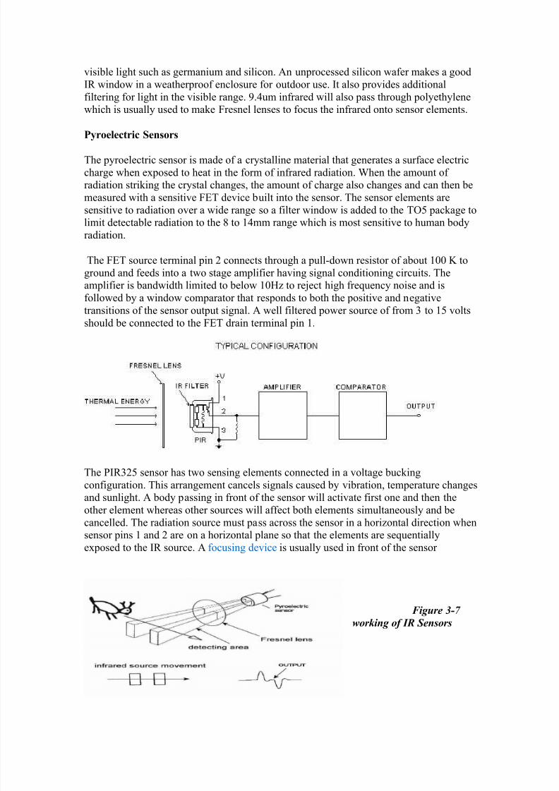
Pyroelectric Sensors
The pyroelectric sensor is made of a crystalline material that generates a surface electric
charge when exposed to heat in the form of infrared radiation. When the amount of radiation striking the crystal changes, the amount of charge also changes and can then be
measured with a sensitive FET device built into the sensor. The sensor elements are
sensitive to radiation over a wide range so a filter window is added to the TO5 package tolimit detectable radiation to the 8 to 14mm range which is most sensitive to human body
radiation.
The FET source terminal pin 2 connects through a pull-down resistor of about 100 K to
ground and feeds into a two stage amplifier having signal conditioning circuits. Theamplifier is bandwidth limited to below 10Hz to reject high frequency noise and is
followed by a window comparator that responds to both the positive and negative
transitions of the sensor output signal. A well filtered power source of from 3 to 15 volts
should be connected to the FET drain terminal pin 1.
The PIR325 sensor has two sensing elements connected in a voltage bucking
configuration. This arrangement cancels signals caused by vibration, temperature changesand sunlight. A body passing in front of the sensor will activate first one and then the
other element whereas other sources will affect both elements simultaneously and be
cancelled. The radiation source must pass across the sensor in a horizontal direction whensensor pins 1 and 2 are on a horizontal plane so that the elements are sequentially
exposed to the IR source. A focusing device is usually used in front of the sensor
Figure 3-7
working of IR Sensors

7/29/2019 Embedded Systems and Avionics
http://slidepdf.com/reader/full/embedded-systems-and-avionics 41/58
Fresnel Lens
A Fresnel lens (pronounced FrennelFresnel) is a Plano Convex lens that has been
collapsed on itself to form a flat lens that retains its optical characteristics but is muchsmaller in thickness and therefore has less absorption losses.
Our FL65 Fresnel lens is made of an infrared transmitting material that has an IR
transmission range of 8 to 14um which is most sensitive to human body radiation. It is
designed to have its grooves facing the IR sensing element so that a smooth surface is presented to the subject side of the lens which is usually the outside of an enclosure that
houses the sensor.
The lens element is round with a diameter of 1 inch and has a flange that is 1.5 inches
square. This flange is used for mounting the lens in a suitable frame or enclosure.
Mounting can best and most easily be done with strips of Scotch tape. Silicone rubber canalso be used if it overlaps the edges to form a captive mount. The FL65 has a focal length
of 0.65 inches from the lens to the sensing element. It has been determined by experimentto have a field of view of approximately 10 degrees when used with a PIR325
Pyroelectric sensor.
3.5.2 COMPARATOR
A comparator is a circuit which compares a signal voltage applied at one input of
an op-amp with a known reference voltage at the other input, and produces either a highor a low output voltage, depending on which input is higher. The input / outputcharacteristics of a comparator is as shown.

7/29/2019 Embedded Systems and Avionics
http://slidepdf.com/reader/full/embedded-systems-and-avionics 42/58
The sensor circuit is redrawn using the comparator, and this is shown below. The sensor
circuit is redrawn using the comparator, and this is shown below.
Figure 3-8 IR sensor circuit
The reference voltage is generated by the 20k POT and given to all the comparators to the
non-inverting input. When the respective sensor is on the line, the emitted light is
absorbed by the line and the transistor is the cut-off mode, thus a potential of 4.6V isgiven to the inverting input which is greater than Vref (which is chosen to be 2.5V), thus
the output of the comparator goes low. When the sensor is not on the line (reflective
white surface) the potential across the detector is usually 0.6V. Thus the output of thecomparator goes high (the non-inverting input has a greater potential). Thus the output of
the comparator goes low only when the sensor is over the line. The comparator is open
collector, and hence a pull-up resistor of 10 k Ω is required at the output
In a similar way we can use this microcontroller to control various other equipment’s like
the keypad control, many RF circuit based equipment’s etc. which can be studied in
reference[7-9]. 7-9
Programs related to LCD and dc motor control are given in Appendix 1
After going through the various equipments we studied during our internship, in the next
chapter we will manifest the knowledge that we acquired and use those to build our
desired project termed as the ‘Obstacle Detector Robot ‘
7/29/2019 Embedded Systems and Avionics
http://slidepdf.com/reader/full/embedded-systems-and-avionics 43/58
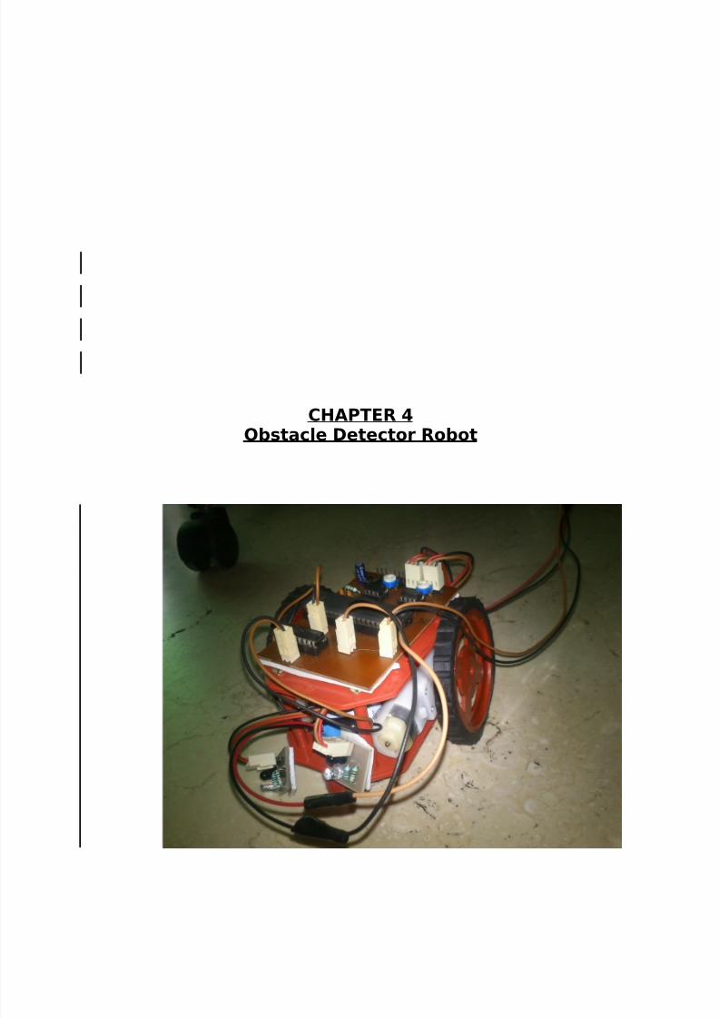
CHAPTER 4Obstacle Detector Robot

7/29/2019 Embedded Systems and Avionics
http://slidepdf.com/reader/full/embedded-systems-and-avionics 44/58
OBSTACLE DETECTOR
AIM: This robot with the help of its microcontroller fitted with IR sensors will automatically
detect the presence of obstacles and perform the desired effect to avoid it
The main components incorporated into the hardware are given below:
• The ATMEL microcontroller
• The voltage regulator and supporting components.
• Crystal oscillator (4MHz)
• The H-bridge motor control IC (L293D)
• Series Wound DC Motors
• 5V, 9V Lead-Acid battery.
• A pair of LM358 IR interrupt sensor, modified to be a reflective sensor.
• Connectors to join the different boards to form one functional device.
Each of the hardware is dissected and was designed/implemented separately for their
functional and later incorporated as one whole application. This helped in the debugging
processes. The block diagram for the same has been given down under:
4.1 DESIGN AND IMPLEMENTATION
Firstly the design to be implemented is tested computationally by simulating it using variouscircuit simulation platforms like the one we used termed as PROTEUS.
7/29/2019 Embedded Systems and Avionics
http://slidepdf.com/reader/full/embedded-systems-and-avionics 45/58
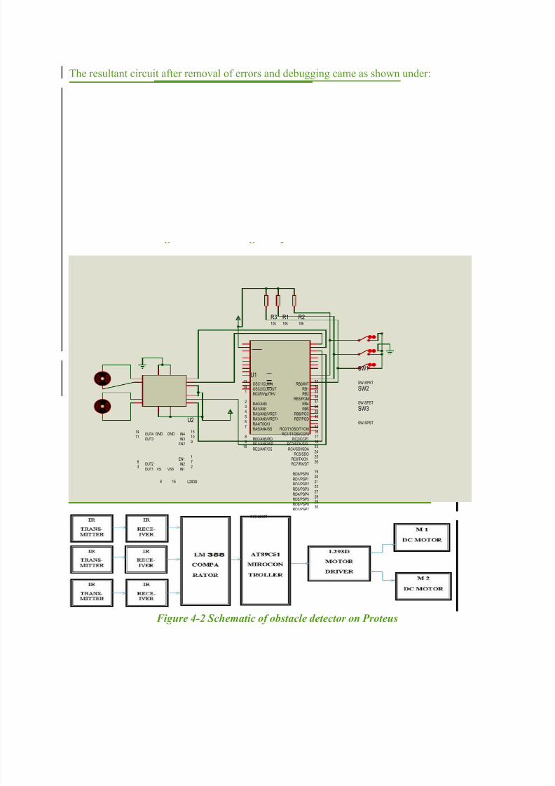
The resultant circuit after removal of errors and debugging came as shown under:
Figure 4-1 block Diagram of Obstacle Detector Robot
RA0/AN02
RA1/AN13
RA2/AN2/VREF-4
RA4/T0CKI6
RA5/AN4/SS7
RE0/AN5/RD8
RE1/AN6/WR9
RE2/AN7/CS10
OSC1/CLKIN13
OSC2/CLKOUT14
RC1/T1OSI/CCP216
RC2/CCP117
RC3/SCK/SCL18
RD0/PSP019
RD1/PSP120
RB7/PGD40RB6/PGC 39
RB538
RB437
RB3/PGM36
RB235
RB134
RB0/INT33
RD7/PSP730
RD6/PSP629
RD5/PSP528
RD4/PSP427
RD3/PSP322
RD2/PSP221
RC7/RX/DT26
RC6/TX/CK25
RC5/SDO24
RC4/SDI/SDA23
RA3/AN3/VREF+5
RC0/T1OSO/T1CKI15
MCLR/Vpp/THV1
U1
PIC16F877
IN12
OUT13
OUT26
OUT311
OUT414
IN27
IN310
IN415
EN11
EN29
VS
8
VSS
16
GNDGND
U2
L293D
SW1
SW-SPST
SW2
SW-SPST
SW3
SW-SPST
R110k
R210k
R310k
Figure 4-2 Schematic of obstacle detector on Proteus

7/29/2019 Embedded Systems and Avionics
http://slidepdf.com/reader/full/embedded-systems-and-avionics 46/58
4.2 SCHEMATIC
Figure 4-3: MICROCONTROLLER INTERFACE WITH L293D TO CONTROL DC MOTOR
The sensor used for obstacle detection is the most crucial part of our Robot whose Circuit
diagram as shown below. :
Figure 4-4 Sensor Array

7/29/2019 Embedded Systems and Avionics
http://slidepdf.com/reader/full/embedded-systems-and-avionics 47/58
4.2.1 THE MICROCONTROLLER
The ATMEL microcontroller was used as it’s a RISC processor which is better suited
for real-time operations. Thus the midrange devices were chosen.
4.2.2 CRYSTAL OSCILLATOR
The clock frequency is provided by one 4Mhz crystal which is connected across the OSC1 &OSC2 pins as shown above. This provides an instruction execution time of 1µs.
4.2.3 VOLTAGE REGULATOR
It has been shown that practically all electronic devices need DC supply. A direct voltage of
constant magnitude requires to be supplied, for the smooth and efficient functioning of these
devices.
A properly designed voltage regulator ensures that, irrespective of change in supply voltage,
load impedance or temperature, the DC supply is maintained at a constant level. This is
achieved by incorporating some type of feedback in the regulator circuit.
An IC voltage regulator unit contains all the circuitry required in a single IC. Thus there are
no discrete components and the circuitry needed for the reference source, the comparator and
control elements are fabricated on a single chip. Even the over load and short-circuit
protection mechanism is integrated into the IC. IC voltage regulators are designed to provide
either a fixed positive or negative voltage, or an adjustable voltage which can be set for any
value ranging between two voltage levels.
Figure 4-5 Voltage Regulators
The circuit requires two voltage sources; one for the digital IC’s (+5V) and a+12-17 V to the
motors. The motor is supplied 17V unregulated supply directly from the battery as regulation
would be difficult and unnecessary; whereas the digital IC’s and the microcontroller require a perfect ripple free +5V to function properly. The L7805C is a 5V voltage regulator IC. The
capacitors added to the input of the voltage regulator are to isolate the spikes generated by the
motor from the input and to reduce noise. The 10µF capacitor at the output is to maintain
stability and improve regulation. These are standard values. The 0.1µF capacitor is used at
the input because of the fact that high value capacitors have poor high frequency response.
Note: in our project we have instead provided 5v supply to the IC and sensors and 9 volt
supply to dc motor through separate supply points.
4.2.4 BATTERY

7/29/2019 Embedded Systems and Avionics
http://slidepdf.com/reader/full/embedded-systems-and-avionics 48/58
Motors on a robot consume most of the power. For most of them, each DC motor consumes
1.5W on the average. For differential steering, two DC motors consume up to 3W. By
comparison, the logic components draw a total of about 80mA. Even at a supply voltage of
12V, the logic component only consumes 1W.
If we assume the whole robot consume 5W, it requires 4500J of energy to last 15Minutes. If we use a 12V battery, it must have a capacity of 4500J/12V=375Asec or
104mAH. This may imply that getting a battery of 150mAH is sufficient. Unfortunately, the
discharge curve of a 150mAH will not sustain the required voltage for 15 minutes.
4.3 USE OF SERIES WOUND DC MOTOR IMPLEMENTING PWM SPEED
CONTROL TECHNIQUE:
The purpose of a motor speed controller is to take a signal representing the demanded speed,
and to drive a motor at that speed. The controller may or may not actually measure the speed
of the motor. If it does, it is called a Feedback Speed Controller or Closed Loop Speed
Controller, if not it is called an Open Loop Speed Controller. Feedback speed control is better, but more complicated, and may not be required for a simple robot design.
Motors come in a variety of forms, and the speed controller's motor drive output will be
different dependent on these forms. The speed controller presented here is designed to drive a
simple cheap starter motor from a car, which can be purchased from any scrap yard. These
motors are generally series wound, which means to reverse them, they must be altered
slightly, (see the section on motors).
4.3.1 L293D Dual H-Bridge Motor Driver
L293D is a dual H-Bridge motor driver, So with one IC we have interfaced two DC motors
which can be controlled in both clockwise and counter clockwise direction and if we
have motor with fix direction of motion that we can make use of all the four I/Os to
connect up to 4 DC motors. L293D has output current of 600mA and peak output current of
1.2A per channel. Moreover for protection of circuit from back EMF output diodes are
included within the IC. The output supply (VCC2) has a wide range from 4.5V to 36V,
which has made L293D a best choice for DC motor driver.
A simple schematic for interfacing a DC motor using L293D is shown on the following
page:

7/29/2019 Embedded Systems and Avionics
http://slidepdf.com/reader/full/embedded-systems-and-avionics 49/58
As we can see in the circuit, three pins are needed for interfacing a DC motor (A, B, Enable).
If we want the o/p to be enabled completely then you can connect Enable to VCC and only 2
pins needed from controller to make the motor work.
Before proceeding ahead recall the concept of H-Bridge and its circuitry to direction of flow
of current.
4.3.2 THE H-BRIDGE CIRCUIT
As we change the output values of the IN1, IN2 … we can control the two motors and thus
move the Robot in the desired direction by the directional steering method as explained
above.
IN1 IN2 IN3 IN4 ACTION
1 0 1 0 BOTH MOTORS FORWARD
(MOVE FORWARD)
0 1 0 1 BOTH MOTORS BACKWARD
(MOVE BACKWARD)1 0 0 1 RIGHT MOTOR BACKWARD
LEFT MOTOR FORWARD
(TURN RIGHT)
0 1 1 0 RIGHT MOTOR FORWARD
LEFT MOTOR BACKWARD
(TURN LEFT)

7/29/2019 Embedded Systems and Avionics
http://slidepdf.com/reader/full/embedded-systems-and-avionics 50/58
As per the truth mentioned in the image above its fairly simple to program
the microcontroller. It’s also clear from the truth table of BJT circuit and L293D that the
programming will be same for both of them, just keeping in mind the allowed combinations
of A and B. We will discuss about programming in C as well as assembly for
running motor with the help of ac microcontroller.
The total number of directional control signals required is 4; but as it can be observed in the
above table, IN1 & IN2 are complimentary (and so is IN3 & IN4) that is, both the inputs have
to take the opposite states for a safe operation. This is done by connecting D L to IN1 L and to
IN2. The same is done to IN3 & IN4. Now we have 1 directional control per motor. The
ENABLE of each motor section is given PWM inputs to further improve on the control.
Now, each motor has a direction control and a speed control. The clamping diodes are built
into the chip which prevent the back EMF generated by the motors to harm the H-bridge.
4.3.3 MOTOR CONTROL CIRCUIT USING H BRIDGE
A common use of the H bridge is an inverter. The arrangement is sometimes known as a
single- or three-phase bridge inverter.
The H bridge with a DC supply will generate a square wave voltage waveform across the
load. For a purely inductive load, the current waveform would be a triangle wave, with its
peak depending on the inductance, switching frequency, and input voltage.
Figure 5-6 The motor control .
The entire motor control circuitry is shown in the above figure along with the internal
circuitry of the L293D motor control IC.
4.3.4 PWM SPECIFICATIONS & CALCULATIONS

7/29/2019 Embedded Systems and Avionics
http://slidepdf.com/reader/full/embedded-systems-and-avionics 51/58
The L293D chip can operate on PWM signals up to 5kHz, which was decided to be used.
1/5kHz = [(PR2) + 1] x4×(1/4MHz)×1
200μ s = [(PR2) + 1]×1μ sPR2 = 200-1 = 199 ≈200
Three speeds are used for the Robot and their corresponding duty cycles are 0%, 50% &
96%. These calculations are shown below.
For 0% duty cycle the value to be loaded is obviously zero,
For 50 % duty cycle,
PWM duty cycle = 200μs
100×50 = 100 μ s .
100μs = [DCx] •0.25μ s • 1
DCx = 400 = 110010000b
Thus, clear the bits DCx(B1) & DCx(B0) and load 1100100b i.e. 100 into the CCPR xL
register.
For 96 % duty cycle,
PWM duty cycle = 200μs
100×96 = 192μ s .
192 μs = [DCx] •0.25μ s • 1
DCx = 768 = 1100000000b
Thus, clear the bits DCx (B1) & DCx (B0) and load 11000000b i.e. 192 into the CCPR xLregister.
4.4 LM358 IR SENSORS IC
RECIEVER TRANSMITTER
The LM358 consists of an infrared emitting diode (λ = 950nm) and an NPN silicon
phototransistor mounted to face each other on a converging optical axis in a black plastic
housing. The phototransistor responds to radiation from the emitting diode only when noobject is present within its field of view. This sensor is physically modified so that the emitter

7/29/2019 Embedded Systems and Avionics
http://slidepdf.com/reader/full/embedded-systems-and-avionics 52/58
and detector face the same direction and thus the modified sensor serves the purpose of an
optical-reflective sensor. The sensor has a focal length of 8mm, thus the surface must be at an
optimum distance of 1.6cm. The original and modified sensors are shown below.
Figure 4-7 Reflective Server
If a reflective (white) surface is present at the optimal distance (d = 1.6cm) then the reflected
waves will strike the detector which on radiation will start to conduct. The circuit diagram is
shown in the figure below.
The drop across the emitter when forward biased is around 1.4V. According to the data
sheets, to have sustained radiation, a max of 40mA must flow through to avoid damage. A
safe margin is allowed and a current of 16mA is considered for the design.for,
R=Vcc-Vd/ Id
Vcc = 5VVd = 1.4V
Id = 16mA
R is calculated to be approximately 220Ω .
For the emitter, the collector resistor was determined experimentally on a trial and error basis.
It was decided to use a value of 56 k Ω. For this value, the potential across the detector is
normally 4.6V, when an object reflects the rays towards the detector, then the potential drops
to 0.6V. The output is obviously analog in nature.
4.4.1 SENSOR ARRAY2 sensors are totally used (A, B).
Figure 4-8 LM358Sensor

7/29/2019 Embedded Systems and Avionics
http://slidepdf.com/reader/full/embedded-systems-and-avionics 53/58
The sensors are mounted on a separate board along with the biasing resistors and a
2 pin connector supplies the power to the sensor array. And the output of each sensor is
connected to the main board via a 3 pin connector to the comparators on the main board.
SENSOR A,B= CONNECTED TO SIDES OF CHESIS
Thus these sensors detect the presence of any obstacle in the optimum region of d=1.6 cm
and based on what side the sensors detects the correspondinng sides motor speed is increased
and the opposite sides is reduced and thus the object can be avoided. This is done every 2.1
msec using the Timer 1 interrupt.
4.6 FUTURE SCOPE &APPLICATION
Application :-

7/29/2019 Embedded Systems and Avionics
http://slidepdf.com/reader/full/embedded-systems-and-avionics 54/58
Obstacle sensing robot can be applied at the toys where small children will play.
It can used for the army application.
We can apply number pairs of IR pairs for the safe direction control of the robot.
In Mines.
The same methodoly has been adopted varios other EM wave sensors like RADAR
etc for many robots.
Future Aspects
We can extend this project with wireless technology by IR (or) RF.
This robot can be used for pick and place the required object by giving directions to
the robot but IR pair should be replaced depending upon the application. By doing extra things, it can be use d in Army application.
RESULT AND CONCLUSION
The Obstacle Detector Robot was finally completed. A lot of effort was put into the design,
implementation and days of toil in front of the computer, writing and debugging the code.
The robot was finally running with a few glitches here and there which we resorted in the
later revisions of the firmware. The line following robot still has a few shortcomings but
achieves most of the objectives.
We earned a lot of knowledge on micro-controllers, a deeper & clearer view of the
architecture, ports & all other functional blocks was achieved. Did a lot of research on
robotics and already have my next project planned. We had a peek look at all simple
functional parts of the project like the crystal oscillator, logic gates and the works. Well,
these were the to ATMEL that we have already dealt with, but We must be honest and admit
that there were various practical issues which one would learn only during a project. There’s
a lot of learning & yet not the end, learning is a continuous never ending process but is
definitely fun.
3.6.2 CONCEPT OF H BRIDGE HARDWARE CONTROL OF DC
MOTOR
What is H-Bridgse ?
An H bridge is an electronic circuit that enables a voltage to be applied across a load in
either direction. These circuits are often used in robotics and other applications to allow DC
motors to run forwards and backwards. The term H Bridge is derived from the typical
graphical representation of such a circuit as shown in fig 2-4.

7/29/2019 Embedded Systems and Avionics
http://slidepdf.com/reader/full/embedded-systems-and-avionics 55/58
Several characteristics are important when selecting DC motors and these can be split into
two specific categories. The first category is associated with the input ratings of the motor
and specifies its electrical requirements, like operating voltage and current.
The second category is related to the motor's output characteristics and specifies the
physical limitations of the motor in terms of speed, torque and power.
Example specifications of the motors used are given below:
Appendix I : C ode for the Obstacle Detector Robot
#include<reg51.h>
sbit m0=P2^0;
sbit m1 =P2^1 ;
sbit m2 =P2^2 ;
sbit m3 =P2^3 ;
sbit s1 =P1^0;
sbit s2 =P1^1;
void main()
{ while(1)
{ while(s1==1&&s2==1)
{ m0=1; m1=0;
m2=1; m3=0;
}
while(s1==1&&s2==0) //rite
{ m0=0; m1=0;
m2=1; m3=0;
}
while(s1==0&&s2==1) //left
{ m0=1; m1=0;
A B C D ACTION
1 0 0 1 CLOCKWISE
0 1 1 0 COUNTER CLOCKWISE
0 1 0 1 BRAKE
1 0 1 0 ANY OTHER STATE FORBIDDEN

7/29/2019 Embedded Systems and Avionics
http://slidepdf.com/reader/full/embedded-systems-and-avionics 56/58
m2=0; m3=0}
while(s1==0&&s2==0)
{ m0=0; m1=0;
m2=0; m3=0;
}
}
}
Appendix II Softwar es required for the coding
Topview Simulator
Topview Simulator gives an excellent simulation environment for the industry's most popular
8 bit Microcontroller family, MCS 51. It gives required facilities to enable the system
designers to start projects right from the scratch and finish them with ease and confidence.
It is the total simulation solution giving many state of art features meeting the needs of the
designers possessing different levels of expertise. If you are a beginner, then you can learn
about 8051 based embedded solutions without any hardware. If you are an experienced
designer, you may find most of the required facilities built in the simulator that enabling you
to complete your next project without waiting for the target hardware.
Its various features can studied in detail from the reference.[12]

7/29/2019 Embedded Systems and Avionics
http://slidepdf.com/reader/full/embedded-systems-and-avionics 57/58
ISIS Schematic Capture or Proteus
ISIS lies at the heart of the Proteus system, and is far more than just another schematics
package. It combines a powerful design environment with the ability to define most aspects
of the drawing appearance. Whether your requirement is the rapid entry of complex designsfor simulation and PCB layout, or the creation of attractive schematics for publication, ISIS is
the tool for the job.[13]
Basic knowledge of programming in C/C++ is a must for carrying out and understanding the
coding involved. We used the KEIL C microcontroller compiler for Embedded C For
acquitting more on that we can have look on the references. [14][15]
REFERENCES
1. www.keil.com/dd/docs/datashts/atmel/at89c51_ds.pdf
2. http://www.nptel.iitm.ac.in/courses/Webcourse-contents/IIT-
KANPUR/microcontrollers/micro/ui/Course_home2_7.html
3. http://www.mikroe.com/chapters/view/64/chapter-1-introduction-to-
microcontrollers/
4. http://www.engineersgarage.com/electronic-components/16x2-lcd-module-
datasheet5. http://www.nxp.com/documents/application_note/APPCHP3.pdf
6. http://www.trossenrobotics.com/c/robot-IR-sensors.aspx
7. http://www.8051projects.net/news-i161-gsm-controlled-robot-project-
report.html
8. http://www.engineersgarage.com/microcontroller/8051projects/stepper-
motor-interfacing-with-8051-microcontroller-circuit
9. http://www.engineersgarage.com/microcontroller/8051projects/alphabetic
-keypad-AT89C51-circuit
10. http://www-
robotics.jpl.nasa.gov/publications/Charles_Bergh/MATTHIES_03_isrr.pdf
11. http://ieeexplore.ieee.org/xpl/articleDetails.jsp?arnumber=614366
12. http://www.frontline-electronics.com/html/simulator8031.html
13. http://www.labcenter.com/products/pcb/schematic_intro.cfm
14. http://www.8051projects.net/keil-c-programming-tutorial/
15. Programming Embedded Systems using C Author(s) Mikael J. Pont Publisher:
Addison-Wesley Professional (May 4, 2002), eBook (2006)
16. www.youtube.com
17. www.google.co.in
18. http://en.wikipedia.org/wiki/Main_Page
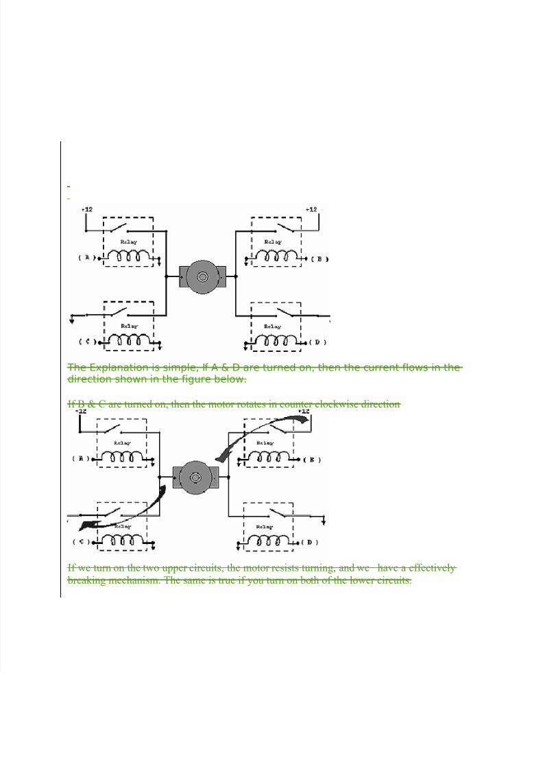
7/29/2019 Embedded Systems and Avionics
http://slidepdf.com/reader/full/embedded-systems-and-avionics 58/58
The Explanation is simple, If A & D are turned on, then the current flows in thedirection shown in the figure below.
If B & C are turned on, then the motor rotates in counter clockwise direction
If we turn on the two upper circuits, the motor resists turning, and we have a effectively
breaking mechanism. The same is true if you turn on both of the lower circuits.