embedded trace buffer - arm information...
TRANSCRIPT

Embedded Trace Buffer(Rev 0)
Technical Reference Manual
Copyright © 2001-2002 ARM Limited. All rights reserved.ARM DDI 0242B

Embedded Trace BufferTechnical Reference Manual
Copyright © 2001-2002 ARM Limited. All rights reserved.
Release Information
Proprietary Notice
Words and logos marked with ® or ™ are registered trademarks or trademarks owned by ARM Limited, except as otherwise stated below in this proprietary notice. Other brands and names mentioned herein may be the trademarks of their respective owners.
Neither the whole nor any part of the information contained in, or the product described in, this document may be adapted or reproduced in any material form except with the prior written permission of the copyright holder.
The product described in this document is subject to continuous developments and improvements. All particulars of the product and its use contained in this document are given by ARM in good faith. However, all warranties implied or expressed, including but not limited to implied warranties of merchantability, or fitness for purpose, are excluded.
This document is intended only to assist the reader in the use of the product. ARM Limited shall not be liable for any loss or damage arising from the use of any information in this document, or any error or omission in such information, or any incorrect use of the product.
Confidentiality Status
This document is Non-Confidential. The right to use, copy and disclose this document may be subject to license restrictions in accordance with the terms of the agreement entered into by ARM and the party that ARM delivered this document to.
Product Status
The information in this document is final, that is for a developed product.
Web Address
http://www.arm.com
Change history
Date Issue Change
18 December 2001 A First release.
5 February 2002 B Changes to signal names and add integration chapter.
ii Copyright © 2001-2002 ARM Limited. All rights reserved. ARM DDI 0242B

ContentsEmbedded Trace Buffer Technical Reference Manual
PrefaceAbout this document ...................................................................................... xFeedback ..................................................................................................... xiii
Chapter 1 Introduction1.1 About the Embedded Trace Buffer ............................................................. 1-21.2 ETM versions and variants .......................................................................... 1-4
Chapter 2 Functional Description2.1 Functional information ................................................................................. 2-22.2 Operation .................................................................................................... 2-42.3 Control logic ................................................................................................ 2-62.4 Data Formatter ............................................................................................ 2-82.5 Trigger delay counter ................................................................................ 2-172.6 Address generation ................................................................................... 2-182.7 BIST interface ........................................................................................... 2-192.8 TAP controller ........................................................................................... 2-202.9 Trace RAM interface ................................................................................. 2-222.10 Clocks, transfers, and resets ..................................................................... 2-24
ARM DDI 0242B Copyright © 2001-2002 ARM Limited. All rights reserved. iii

Contents
Chapter 3 Programmer’s Model3.1 About the programmer’s model .................................................................. 3-23.2 Register descriptions .................................................................................. 3-43.3 Software access to the ETB using the AHB interface .............................. 3-103.4 Potential limitations ................................................................................... 3-12
Chapter 4 Timing Requirements4.1 AHB interface ............................................................................................. 4-24.2 CLK domain ................................................................................................ 4-44.3 IEEE1149.1 Interface ................................................................................. 4-6
Appendix A Signal DescriptionsA.1 Signal properties and requirements ............................................................ A-2A.2 Signal descriptions ..................................................................................... A-3
Appendix B Integrating the ETBB.1 Connection guide ........................................................................................ B-2B.2 Integrating the ETB with an ETMv1 device ................................................ B-3B.3 Integrating the ETB with an ETMv2 device ................................................ B-5B.4 Integrating the ETB with a generic trace port interface device ................... B-7B.5 Connecting the ETB in a 64-bit AHB system .............................................. B-8
Glossary
iv Copyright © 2001-2002 ARM Limited. All rights reserved. ARM DDI 0242B

List of TablesEmbedded Trace Buffer Technical Reference Manual
Change history .............................................................................................................. iiTable 1-1 ETM versions and variants ........................................................................................ 1-4Table 2-1 ETMv1 TRACEOUTPUT pin connections ................................................................. 2-9Table 2-2 ETMv1 8-bit demultiplexed TRACEOUTPUT pin connections ................................ 2-10Table 2-3 ETMv2 TRACEOUTPUT pin connections ............................................................... 2-12Table 2-4 ETMv2 8-bit demultiplexed TRACEOUTPUT pin connections ................................ 2-12Table 2-5 Generic trace port interface TRACEOUTPUT pin connections ............................... 2-15Table 2-6 PORTSIZE[2:0] encoding ........................................................................................ 2-16Table 2-7 Supported public instructions .................................................................................. 2-21Table 2-8 Trace RAM interface signals ................................................................................... 2-22Table 3-1 Register map ............................................................................................................. 3-2Table 3-2 RAM depth register ................................................................................................... 3-4Table 3-3 RAM width register .................................................................................................... 3-5Table 3-4 Status register ........................................................................................................... 3-5Table 3-5 RAM data register ..................................................................................................... 3-6Table 3-6 RAM read pointer register ......................................................................................... 3-7Table 3-7 RAM write pointer register ......................................................................................... 3-7Table 3-8 Trigger count register ................................................................................................ 3-8Table 3-9 Control register .......................................................................................................... 3-9Table 3-10 Registers that require software access ................................................................... 3-10Table 4-1 AHB interface timing requirements ........................................................................... 4-2
ARM DDI 0242B Copyright © 2001-2002 ARM Limited. All rights reserved. v

List of Tables
Table 4-2 CLK domain timing requirements ............................................................................. 4-4Table 4-3 IEEE1149.1 interface timing requirements ............................................................... 4-6Table A-1 Signal descriptions .................................................................................................... A-3Table B-1 ETB connection guide ............................................................................................... B-2Table B-2 ETB to ETMv1 connections for normal mode ........................................................... B-3Table B-3 ETB to ETMv1 connections for demultiplexed mode ................................................ B-3Table B-4 ETB to ETMv2 connections for normal mode ........................................................... B-5Table B-5 ETB to ETMv2 connections for demultiplexed mode ................................................ B-5Table B-6 ETB to generic trace port interface connections ....................................................... B-7
vi Copyright © 2001-2002 ARM Limited. All rights reserved. ARM DDI 0242B

List of FiguresEmbedded Trace Buffer Technical Reference Manual
Key to timing diagram conventions .............................................................................. xiFigure 1-1 SoC debug implementation ....................................................................................... 1-2Figure 2-1 ETB module block diagram ....................................................................................... 2-3Figure 2-2 Trace capture operation ............................................................................................ 2-6Figure 2-3 Trace read operation ................................................................................................. 2-7Figure 2-4 Data formatter block diagram .................................................................................... 2-8Figure 2-5 RAM data word definition for ETMv1 ...................................................................... 2-11Figure 2-6 RAM data word definition for ETMv2 ...................................................................... 2-14Figure 2-7 RAM data word definition for a generic trace port interface .................................... 2-15Figure 2-8 BIST interface block diagram .................................................................................. 2-19Figure 2-9 Read access from Trace RAM timing diagram ........................................................ 2-22Figure 2-10 Write access to Trace RAM timing diagram ............................................................ 2-23Figure 2-11 Synchronization logic between HCLK and CLK domains ....................................... 2-26Figure 2-12 Software read cycle with asynchronous CLK and HCLK ........................................ 2-27Figure 2-13 Software read cycle with synchronous CLK and HCLK .......................................... 2-28Figure 2-14 Software write cycle with asynchronous CLK and HCLK ........................................ 2-30Figure 2-15 Software write cycle with synchronous CLK and HCLK .......................................... 2-31Figure 2-16 Example nRESET synchronizer .............................................................................. 2-32Figure 4-1 AHB interface signals ................................................................................................ 4-2Figure 4-2 CLK domain signals .................................................................................................. 4-4Figure 4-3 IEEE1149.1 interface signals .................................................................................... 4-6
ARM DDI 0242B Copyright © 2001-2002 ARM Limited. All rights reserved. vii

List of Figures
viii Copyright © 2001-2002 ARM Limited. All rights reserved. ARM DDI 0242B

Preface
This preface introduces the Embedded Trace Buffer (ETB) and its reference documentation. It contains the following sections:
• About this document on page x
• Feedback on page xiii.
ARM DDI 0242B Copyright © 2001-2002 ARM Limited. All rights reserved. ix

Preface
About this document
This document is the technical reference manual for the ETB.
Intended audience
This document has been written for experienced hardware and software engineers who want to design or obtain trace information from chips that use ARM cores with the ETM facility.
Using this manual
This document is organized into the following chapters:
Chapter 1 Introduction
Read this chapter for an overview of the ETB.
Chapter 2 Functional Description
Read this chapter for a description of the major functional blocks, configurability, read and write timing information, clocks, and resets.
Chapter 3 Programmer’s Model
Read this chapter for a description of the registers and programming information.
Chapter 4 Timing Requirements
Read this chapter for a description of the ETB AC timing requirements.
Appendix A Signal Descriptions
This appendix lists the ETB signals.
Appendix B Integrating the ETB
This appendix describes how to integrate the ETB if you are not using a Macrocell Integration Kit (MIK).
Typographical conventions
The following typographical conventions are used in this document:
bold Highlights ARM processor signal names, and interface elements such as menu names. Also used for terms in descriptive lists, where appropriate.
italic Highlights special terminology, cross-references, and citations.
x Copyright © 2001-2002 ARM Limited. All rights reserved. ARM DDI 0242B

Preface
monospace Denotes text that can be entered at the keyboard, such as commands, file names and program names, and source code.
monospace Denotes a permitted abbreviation for a command or option. The underlined text can be entered instead of the full command or option name.
monospace italic
Denotes arguments to commands or functions where the argument is to be replaced by a specific value.
monospace bold
Denotes language keywords when used outside example code.
Timing diagram conventions
This manual contains one or more timing diagrams. The key timing diagram shown below explains the components used in these diagrams. Any variations are clearly labeled when they occur. Therefore, no additional meaning must be attached unless specifically stated.
Key to timing diagram conventions
Shaded bus and signal areas are undefined, so the bus or signal can assume any value within the shaded area at that time. The actual level is unimportant and does not affect normal operation.
Clock
HIGH to LOW
Transient
HIGH/LOW to HIGH
Bus stable
Bus to high impedance
Bus change
High impedance to stable bus
ARM DDI 0242B Copyright © 2001-2002 ARM Limited. All rights reserved. xi

Preface
Further reading
This section lists publications by ARM Limited, and by third parties.
ARM periodically provides updates and corrections to its documentation. See http://www.arm.com for current errata sheets and addenda.
See also the ARM Frequently Asked Questions list at: http://www.arm.com/DevSupp/Sales+Support/faq.html
ARM publications
This document contains information that is specific to the ETB. Refer to the following documents for other relevant information:
• Embedded Trace Buffer (Rev 0) Implementation Guide (ARM DII 0035)
• ARM Architecture Reference Manual (ARM DDI 0100)
• ARM AMBA Specification (Rev 2.0) (ARM IHI 0001)
• Embedded Trace Macrocell Specification (ARM IHI 0014)
• ETM7 (Rev 1) Technical Reference Manual (ARM DDI 0158)
• ETM9 (Rev 1) Technical Reference Manual (ARM DDI 0157)
• Multi-ICE System Design Considerations (ARM DAI 0072)
• Multi-layer AHB Overview (ARM DVI 0045).
xii Copyright © 2001-2002 ARM Limited. All rights reserved. ARM DDI 0242B

Preface
Feedback
ARM Limited welcomes feedback both on the ETB, and on the documentation.
Feedback on the ETB
If you have any comments or suggestions about this product, please contact your supplier giving:
• the product name
• a concise explanation of your comments.
Feedback on this document
If you have any comments on about this document, please send email to [email protected] giving:
• the document title
• the document number
• the page number(s) to which your comments refer
• a concise explanation of your comments.
General suggestions for additions and improvements are also welcome.
ARM DDI 0242B Copyright © 2001-2002 ARM Limited. All rights reserved. xiii
Preface
xiv Copyright © 2001-2002 ARM Limited. All rights reserved. ARM DDI 0242B

Chapter 1 Introduction
This chapter introduces the ETB and its features. It contains the following sections:
• About the Embedded Trace Buffer on page 1-2
• ETM versions and variants on page 1-4.
ARM DDI 0242B Copyright © 2001-2002 ARM Limited. All rights reserved. 1-1

Introduction
1.1 About the Embedded Trace Buffer
As process speeds increase it is increasingly difficult to obtain trace information off a chip from an Embedded Trace Macrocell (ETM). This causes difficulties in maintaining acceptable signal quality or the signals need to be demultiplexed on to what can become a very large number of trace port pins.
The solution is to provide a buffer area on-chip where the trace information is stored, and read from the chip later, at a slower rate.
The ETB stores data produced by the ETM. The buffered data can then be accessed by the debugging tools using a JTAG (IEEE 1149.1) interface, as shown in Figure 1-1.
Figure 1-1 SoC debug implementation
Providing an on-chip buffer enables the trace data generated by the ETM (at the system clock rate) to be read by the debugger at a reduced clock rate. This removes the requirement for high-speed pads for the trace data.
System-on-Chip
PC-based
debugging
tool
JTAG
interface unit
Trace BufferARM processor
Peripherals
Embedded
ICE
Trace
RAM
Ethernet
ETM
On-chip
ROM
On-chip
RAM
AHB bus
JTAG
1-2 Copyright © 2001-2002 ARM Limited. All rights reserved. ARM DDI 0242B

Introduction
This buffered data can also be accessed through an AHB slave-based memory-mapped peripheral included as part of the ETB. This enables software running on the processor to read the trace data generated by the ETM.
The major blocks shown in Figure 1-1 on page 1-2 are:
ETM The ETM monitors the ARM core buses and passes compressed information in real-time to the ETB where it is stored for later retrieval. The data is then passed through the JTAG trace port to an interface unit. This is an external hardware device that passes the information from the trace port to a debugging tool, for example, a PC. The debug tool:
• retrieves data from the interface unit
• reconstructs an historical view of the processor's activity including data accesses
• configures the macrocell through the JTAG interface unit and port.
User-definable filters allow you to limit the amount of information captured in search of a bug, reducing upload time from the trace port analyzer.
EmbeddedICE
EmbeddedICE is a JTAG based debugging environment for ARM microprocessors. EmbeddedICE provides the interface between the ARM source level symbolic debugger, ARMxd, and an ARM microprocessor embedded within any ASIC. The ARMxd debugger is available for PC compatible and Sun workstation platforms.
EmbeddedICE provides
• real time address and data dependant breakpoints
• single stepping
• full access and control of the ARM CPU
• access to the ASIC system.
EmbeddedICE also allows the embedded microprocessor to access the host system peripherals, for instance screen display, keyboard input and disk drive storage.
JTAG interface
Boundary scan is a methodology allowing complete controllability and observability of the boundary pins of a JTAG compatible device by software control. This capability enables in-circuit testing without requiring specially designed in-circuit test equipment.
ARM DDI 0242B Copyright © 2001-2002 ARM Limited. All rights reserved. 1-3

Introduction
1.2 ETM versions and variants
The ETB is designed to work with all versions and variants of the ETM. The ETM is subject to a program of continuous improvement in conjunction with the development of the ARM processors. The history of the ETM is listed in Table 1-1.
The ETB has modes for compatibility with ETMv1 and ETMv2 architecture devices. The ETB is also suitable for the generic trace port interface so that it is compatible with future architecture versions.
Table 1-1 ETM versions and variants
NameMajorarchitectureversion
ETM7 Rev 0 ETMv1
ETM7 Rev 1 ETMv1
ETM7 Rev 1a ETMv1
ETM9 Rev 0 ETMv1
ETM9 Rev 0a ETMv1
ETM9 Rev 1 ETMv1
ETM9 Rev 2 ETMv1
ETM9 Rev 2a ETMv1
ETM10 Rev 0 ETMv2
1-4 Copyright © 2001-2002 ARM Limited. All rights reserved. ARM DDI 0242B

Chapter 2 Functional Description
This chapter describes how the ETB operates. It contains the following sections:
• Functional information on page 2-2
• Operation on page 2-4
• Control logic on page 2-6
• Data Formatter on page 2-8
• Trigger delay counter on page 2-17
• Address generation on page 2-18
• BIST interface on page 2-19
• TAP controller on page 2-20
• Trace RAM interface on page 2-22
• Clocks, transfers, and resets on page 2-24.
ARM DDI 0242B Copyright © 2001-2002 ARM Limited. All rights reserved. 2-1

Functional Description
2.1 Functional information
This section provides basic functional information:
• Interfaces
• Global configurability
• ETM version compatibility on page 2-3.
2.1.1 Interfaces
The on-chip ETB module has three primary interfaces:
• the trace port from the ETM
• a 5-pin IEEE 1149.1 (JTAG) interface
• an AHB slave-based memory-mapped peripheral to give software access to the ETB registers.
Additionally, the ETB accesses a trace RAM that must be implemented in the target technology. It is not possible to provide a single generic RAM interface block because of the large number of different RAMs that can be integrated. Therefore, the RAM interface is specified but the RAM block must be supplied by the system integrator. The RAM interface is described in Trace RAM interface on page 2-22.
A block diagram of the ETB module is shown in Figure 2-1 on page 2-3.
2.1.2 Global configurability
To enable the depth of the trace RAM to be configured in the RTL, three constants are used:
• RAM_ADDR_WIDTH is used to define:
— the width of the trace RAM address bus, read pointer register, and write pointer register.
— the width of the trigger counter register
— the value read from the RAM depth register.
The RAM address width can be a maximum of 32 bits. The define parameter RAM_ADDR_WIDTH and a derived parameter MSB_ADDR are in the file EtbDefs.v.
• RAM_BIT_WIDTH is used to enable the bit width (24 or 32 bits) of the trace RAM to be configured in the RTL.
Use 32-bit trace RAM if you intend to use:
— the ETB as system memory when not collecting trace
2-2 Copyright © 2001-2002 ARM Limited. All rights reserved. ARM DDI 0242B

Functional Description
— all 32 bits of TRACEOUTPUT.
Otherwise use 24-bit trace RAM.
• BYTE_WRITE indicates that the trace RAM supports byte writes. This must be true if the ETB is used as system memory.
Figure 2-1 ETB module block diagram
2.1.3 ETM version compatibility
The ETB is compatible with all ETM architecture versions. This includes all current and planned devices. The way that the trace data is formatted differs between ETM versions. These differences are described in Data Formatter on page 2-8.
Control
logic
Memory-
mapped
peripheral
Data
Formatter
TAP controller
Trace
RAM
DataValid
AcqComp/
control reg
Addr[(RAW-1):0]
ReadData[RBW-1:0]
Read
Ad
drU
p
Read
Ad
drI
nc
Tra
ceC
ap
tEn
Configuration
Status
Trace buffer
Din
WR
CS
A
Dout
TCK TMS TDI TDOnTRSTTCKEN
PORTSIZE[2:0]
TRACEOUTPUT[(RBW-1):0]
TRACEVALID
TRIGGER
AHB interface signals
Register
control
Triggered
HCLK/CLK
synchronization
Read/write
control signals
Control
register
PROTOCOL[1:0]
WriteData[(RBW-1):0]
RBW=RAM_BIT_WIDTH
RAW=RAM_ADDRESS_WIDTH
RAMAccess
nR/W
ACQCOMP
FULL
nRESET
CLK
ARM DDI 0242B Copyright © 2001-2002 ARM Limited. All rights reserved. 2-3

Functional Description
2.2 Operation
The on-chip ETB operates as follows:
1. The ETM architecture version in use is supplied to the Data Formatter using the PROTOCOL[1:0] signal:
• PROTOCOL[1:0]=b00 for ETMv1 architecture.
• PROTOCOL[1:0]=b01 for ETMv2 architecture.
• PROTOCOL[1:0]=b10 for generic architecture, the Data Formatter is bypassed and RAM_DATA_WIDTH bits are written at a time (DataValid=TRACEVALID)
• PROTOCOL[1:0]=b11 is reserved.
2. Configuration registers are set-up through the TAP controller or through the memory-mapped peripheral.
3. Trace capture is enabled using the control register. This asserts the TraceCaptEn signal, which enables the Data Formatter and the control logic to capture and store the trace data. The Data Formatter assembles trace packets into 24-bit datawords for ETMv1 and ETMv2, and 32-bit data words for the generic trace port interface (see Data Formatter on page 2-8). When the Data Formatter has a complete dataword the DataValid signal is asserted and the control logic writes the data into the trace RAM. The DataValid signal also causes the write address pointer to increment. If the write pointer overflows, the Full status signal is set.
4. Trace data is continuously written into the trace RAM if the ETB is enabled and the trigger counter value is nonzero. A trigger event code from the ETM enables the trigger counter, which subsequently decrements when DataValid is asserted. A trigger event is represented in the different ETM versions by the following conventions:
ETMv1 PIPESTAT[2:0]=6 OR TRIGGER=1
ETMv2 PIPESTAT[3:0]=6 OR TRIGGER=1
Generic trace port interface TRIGGER=1
When the trigger counter reaches zero the acquisition complete (AcqComp) flag is activated. The control logic then prevents further writes to the trace RAM. The value loaded into the trigger counter sets the number of data words stored in the trace RAM after a trigger event.
2-4 Copyright © 2001-2002 ARM Limited. All rights reserved. ARM DDI 0242B

Functional Description
5. The debugging tools through the TAP controller can read trace data stored in the trace RAM. To read data through the TAP controller you must:
a. Disable trace capture. If trace capture is enabled when the RAM data register is accessed, the RAM value read is incorrect.
b. Write the location that data is read from into the read pointer register.
c. Read the RAM data register to return the data at the address stored in the read pointer register. The read address pointer increments after each RAM data register read and the next data value is automatically read from the RAM and stored in the RAM data register.
Note You must precede the read access by a write to the read pointer register to
ensure that the first RAM read register access returns valid data.
6. The trace data can also be read by the AHB interface. The trace RAM will be aliased into the system memory space. This means that reading a value from the trace RAM requires an LDR type instruction from the trace RAM address space. The memory-mapped peripheral can also write to the ETB memory when trace capture is disabled.
7. There are three internal status signals:
• AcqComp• Triggered• Full.
These can be read at any time while trace capture is in progress. The status signals are cleared when TraceCaptEn is cleared.
ARM DDI 0242B Copyright © 2001-2002 ARM Limited. All rights reserved. 2-5

Functional Description
2.3 Control logic
Control logic monitors the TraceCaptEn signal, the status flags and the DataValid signal from the Data Formatter. The logic enables a RAM write access cycle when there is valid data and trace capture is active. Trace capture is active while the TraceCaptEn signal is asserted and TrgDelayCounter is nonzero.
TraceCaptEn directly selects RAM write or read mode and the RAM address source. When TraceCaptEn is asserted all RAM access cycles are writes using the write pointer as the address. When TraceCaptEn is deasserted, RAM accesses are controlled by the memory-mapped peripheral when SoftwareCntl (control register bit 4) is HIGH and SWEN is HIGH. Otherwise, all access cycles are reads using the read pointer register as the address. Timing diagrams showing the operation of the control logic are given in Figure 2-2 and Figure 2-3 on page 2-7.
Figure 2-2 Trace capture operation
D0 D1 D2 D3 D4 D5 D6 D7
CLK
TraceData
TraceCaptEn
W W+1 W+2 W+3 W+4RAMAddr
D0/1 D2/3 D4/50 D6/7 0WriteData
DataValid
RAMAccess
AcqComp
WriteRead ReadControlState
Trace complete
2-6 Copyright © 2001-2002 ARM Limited. All rights reserved. ARM DDI 0242B

Functional Description
Figure 2-3 Trace read operation
CLK
TraceCaptEn
R R+1 UR UR+1RAMAddr
ReadData
RAMAccess
RegAccess
Read WriteControlState
D D+1 UD UD+1
ReadAddInc
Read
ARM DDI 0242B Copyright © 2001-2002 ARM Limited. All rights reserved. 2-7

Functional Description
2.4 Data Formatter
The Data Formatter is used to pack the trace data from the ETM into datawords, that are then written into the trace RAM.
A block diagram of the Data Formatter is shown in Figure 2-4.
Figure 2-4 Data formatter block diagram
Operation of the Data Formatter is described in:
• ETM architecture versions on page 2-9
Data formatter
TRACEOUTPUT[RBW-1:0]
Sel[7:0] En[7:0]
WriteData[3:0]
Control logic
Data
selection
logic
DataValid
WriteData[7:4]
WriteData[11:8]
WriteData[15:12]
WriteData[19:16]
WriteData[23:20]
PORTSIZE
TRACEVALID
TRIGGER
CLK
WriteData[27:24]
WriteData[31:28]
RBW=RAM_BIT_WIDTH
2-8 Copyright © 2001-2002 ARM Limited. All rights reserved. ARM DDI 0242B

Functional Description
• Packet width on page 2-16.
2.4.1 ETM architecture versions
The data format differs between ETM architecture versions. These differences are described in:
• ETMv1 architecture data formats
• ETMv2 architecture data formats on page 2-11
• Generic trace port interface architecture data formats on page 2-15.
ETMv1 architecture data formats
The format of the trace data is dependent on the width of the TRACEPKT data, as shown in Figure 2-5 on page 2-11.
This TRACEOUTPUT bus is made up from the ETM signals:
• TRACESYNC• TRACEPKT• PIPESTAT.
Table 2-1 shows the way that an ETMv1 connects to the TRACEOUTPUT pins.
The ETB also supports a demultiplexed mode. This mode is intended for use with memories that cannot be run at the full speed of the processor clock. In this mode the ETB is clocked at half the rate of the processor clock. Two cycles of trace information are input to the ETB every clock cycle. This is only used in conjunction with an 8-bit trace port and requires the TRACEOUTPUT inputs to be connected up as shown in Table 2-2 on page 2-10.
Table 2-1 ETMv1 TRACEOUTPUT pin connections
Pin Connection
TRACEOUTPUT[RAM_BIT_WIDTH-1:20] Unconnected
TRACEOUTPUT[19] TRACESYNC
TRACEOUTPUT[18:3] TRACEPKT[15:0]
TRACEOUTPUT[2:0] PIPESTAT[2:0]
ARM DDI 0242B Copyright © 2001-2002 ARM Limited. All rights reserved. 2-9

Functional Description
The DataValid flag is asserted for a single clock cycle when a complete data word is available. The Data Formatter removes trace disable cycles from the data stream coming into the ETB by looking for the following conditions:
(PIPESTAT[2:0]=7 AND TRACEPKT[0]=0) OR TRACEVALID=0
For demultiplexed trace ports, the trace information on TRACEOUTPUT[RAM_BIT_WIDTH-1:0] is written to the trace RAM unless both packets are trace disable cycles. ETM trace data is registered immediately to ensure the PIPESTAT[2:0] and TRACEPKT[0] decode logic has a full clock cycle to propagate.
Multiple pipeline registers are used to build the output data value and ensure operation at high clock rates.
A state machine is used to track the construction of the output data value. The state machine controls propagation of data down the Data Formatter pipeline. If trace capture is disabled and the Data Formatter contains a partly built value, the Data Formatter inserts TD packets into the start of the formatter pipeline until the data value is complete. The DataValid flag is derived from the state machine, it is HIGH when the state machine is in one of the three states corresponding to completion of a dataword. The state machine stops when it reaches the idle state and trace capture is disabled.
Trace capture is disabled if either TraceCaptEn is LOW or AcqComp is HIGH.
Table 2-2 ETMv1 8-bit demultiplexed TRACEOUTPUT pin connections
Packet Pin Connection
Packet 1 TRACEOUTPUT[RAM_BIT_WIDTH-1:24] Unconnected
TRACEOUTPUT[23] TRACESYNCA
TRACEOUTPUT[22:15] TRACEPKTA[7:0]
TRACEOUTPUT[14:12] PIPESTATA[2:0]
Packet 2 TRACEOUTPUT[11] TRACESYNCB
TRACEOUTPUT[10:3] TRACEPKTB[7:0]
TRACEOUTPUT[2:0] PIPESTATB[2:0]
2-10 Copyright © 2001-2002 ARM Limited. All rights reserved. ARM DDI 0242B

Functional Description
Figure 2-5 RAM data word definition for ETMv1
ETMv2 architecture data formats
The format of the trace data is dependent on the width of the TRACEPKT data, as shown in Figure 2-6 on page 2-14.
This TRACEOUTPUT bus is made up from the ETM signals:
• TRACESYNC• TRACEPKT• PIPESTAT.
T
S
TRACEPKT
[3:0]
PIPESTAT
[2:0]
23 16 15 8 7 0
T
S
TRACEPKT
[3:0]
PIPESTAT
[2:0]
T
S
TRACEPKT
[3:0]
PIPESTAT
[2:0]
23 22 19 18 16 15 14 11 10 8 7 6 3 2 0
Trace word NTrace word N+1Trace word N+2
4-bit trace data
TRACEPKT
[15:0]
23 19 0
PIPESTAT
[2:0]Reserved
T
S
23 20 19 18 3 2 0
Trace word N
16-bit trace data
20
T
S
TRACEPKT
[7:0]
PIPESTAT
[2:0]
T
S
TRACEPKT
[7:0]
PIPESTAT
[2:0]
23 22 1215 14 11 10 3 2 0
Trace word NTrace word N+1
8-bit trace data
Demultiplexed 8-bit trace dataT
S
TRACEPKT
[7:0]
PIPESTAT
[2:0]
T
S
TRACEPKT
[7:0]
PIPESTAT
[2:0]
23 22 1215 14 11 10 3 2 0
Trace word NTrace word N+1
T
S= TRACESYNC
ARM DDI 0242B Copyright © 2001-2002 ARM Limited. All rights reserved. 2-11

Functional Description
Table 2-3 shows the way that an ETMv2 connects to the TRACEOUTPUT pins.
The ETB also supports a demultiplexed mode. This mode is intended for use with memories that cannot be run at the full speed of the processor clock. In this mode the ETB is clocked at half the rate of the processor clock. Two cycles of trace information are input to the ETB every clock cycle. This is only used in conjunction with an 8-bit trace port and requires the TRACEOUTPUT inputs to be connected up as shown in Table 2-4.
The DataValid flag is asserted for a single clock cycle when a complete data word is available. The Data Formatter removes trace disable cycles from the data stream coming into the ETB by looking for the following conditions:
(PIPESTAT[3:0]=7 AND TRACEPKT[0]=0) OR TRACEVALID=0
Table 2-3 ETMv2 TRACEOUTPUT pin connections
Pin Connection
TRACEOUTPUT[RAM_BIT_WIDTH-1:20] Unconnected
TRACEOUTPUT[19] PIPESTAT[3]
TRACEOUTPUT[18:3] TRACEPKT[15:0]
TRACEOUTPUT[2:0] PIPESTAT[2:0]
Table 2-4 ETMv2 8-bit demultiplexed TRACEOUTPUT pin connections
Packet Pin Connection
Packet 1 TRACEOUTPUT[RAM_BIT_WIDTH-1:24] Unconnected
TRACEOUTPUT[23] PIPESTATA[3]
TRACEOUTPUT[22:15] TRACEPKTA[7:0]
TRACEOUTPUT[14:12] PIPESTATA[2:0]
Packet 2 TRACEOUTPUT[11] PIPESTATB[3]
TRACEOUTPUT[10:3] TRACEPKTB[7:0]
TRACEOUTPUT[2:0] PIPESTATB[2:0]
2-12 Copyright © 2001-2002 ARM Limited. All rights reserved. ARM DDI 0242B

Functional Description
For demultiplexed trace ports, the trace information on TRACEOUTPUT[RAM_BIT_WIDTH-1:0] is written to the trace RAM unless both packets are trace disable cycles. ETM trace data is registered immediately to ensure the PIPESTAT[2:0] and TRACEPKT[0] decode logic has a full clock cycle to propagate.
Multiple pipeline registers are used to build the output data value and ensure operation at high clock rates.
A state machine is used to track the construction of the output data value. The state machine controls propagation of data down the Data Formatter pipeline. If trace capture is disabled and the Data Formatter contains a partly built value, the Data Formatter inserts TD packets into the start of the formatter pipeline until the data value is complete. The DataValid flag is derived from the state machine, it is HIGH when the state machine is in one of the three states corresponding to completion of a dataword. The state machine stops when it reaches the idle state and trace capture is disabled.
Trace capture is disabled if either TraceCaptEn is LOW or AcqComp is HIGH.
ARM DDI 0242B Copyright © 2001-2002 ARM Limited. All rights reserved. 2-13

Functional Description
Figure 2-6 RAM data word definition for ETMv2
P
S= PIPESTAT[3]
P
S
P
S
TRACEPKT
[3:0]
PIPESTAT
[2:0]
23 16 15 8 7 0
TRACEPKT
[3:0]
PIPESTAT
[2:0]
P
S
TRACEPKT
[3:0]
PIPESTAT
[2:0]
23 22 19 18 16 15 14 11 10 8 6 3 2 0
Trace word NTrace word N+1Trace word N+2
4-bit trace data
7
P
S
TRACEPKT
[7:0]
PIPESTAT
[2:0]
P
S
TRACEPKT
[7:0]
PIPESTAT
[2:0]
23 22 1215 14 11 10 3 2 0
Trace word NTrace word N+1
8-bit trace data
TRACEPKT
[15:0]
23 19 0
PIPESTAT
[2:0]Reserved
P
S
23 20 19 18 3 2 0
Trace word N
16-bit trace data
20
Demultiplexed 8-bit trace dataP
S
TRACEPKT
[7:0]
PIPESTAT
[2:0]
P
S
TRACEPKT
[7:0]
PIPESTAT
[2:0]
23 22 1215 14 11 10 3 2 0
Trace word NTrace word N+1
2-14 Copyright © 2001-2002 ARM Limited. All rights reserved. ARM DDI 0242B

Functional Description
Generic trace port interface architecture data formats
Most of the Data Formatter operations are bypassed when connected to a generic trace port interface device. The format of the data in the trace RAM is dependent on the width of the TRACEPKT data, as defined in Figure 2-7. The trace information is received on the TRACEOUTPUT[RAM_BIT_WIDTH-1:0] bus. Table 2-5 shows the way that a generic trace port interface device connects to the TRACEOUTPUT pins.
Demultiplexed mode is ignored when a generic trace port interface device is selected.
The DataValid flag is asserted for a single clock cycle when a complete data word is available. When tracing 16-bit trace data, DataValid can be asserted continuously because valid data can occur on consecutive clock cycles. The Data Formatter removes trace disable cycles from the data stream coming into the ETB by looking for the following conditions:
TRACEVALID=0
If TRACEVALID is HIGH, then all of the trace information on TRACEOUTPUT[RAM_BIT_WIDTH-1:0] is written to the Trace RAM.
Multiple pipeline registers are used to build the output data value and ensure operation at high clock rates.
A state machine is used to track the construction of the output data value. The state machine controls propagation of data down the Data Formatter pipeline.
Figure 2-7 RAM data word definition for a generic trace port interface
Table 2-5 Generic trace port interface TRACEOUTPUT pin connections
Pin Connection
TRACEOUTPUT[RAM_BIT_WIDTH-1:0] TRACEDATA[RAM_BIT_WIDTH-1:0]
TRACEDATA[RAM_BIT_WIDTH-1:0]
RAM_BIT_WIDTH-1 0
Trace data
ARM DDI 0242B Copyright © 2001-2002 ARM Limited. All rights reserved. 2-15

Functional Description
2.4.2 Packet width
The TRACEPKT width is configurable within the ETM, determined by the value of the PORTSIZE[2:0] signals. The PORTSIZE[2:0]signals define the width of the TRACEPKT data as shown in Table 2-6.
Note PORTSIZE is ignored when generic trace port interface is selected because the data width is always RAM_BIT_WIDTH bits. The PORTSIZE signals must not be changed while TraceCaptEn is enabled. If they are changed, this results in an unusable trace and unpredictable behavior of the Data Formatter.
Table 2-6 PORTSIZE[2:0] encoding
PORTSIZE[2:0] TRACEPKT width
000 4 bits
001 8 bits
010 16 bits
011-111 Reserved
2-16 Copyright © 2001-2002 ARM Limited. All rights reserved. ARM DDI 0242B

Functional Description
2.5 Trigger delay counter
The trigger delay counter (TrgDelayCounter) controls how many data words are written into the trace RAM after a trigger event. When a trigger event is detected, the triggered flag is asserted. This enables the trigger delay counter which decrements every time a data word is written into the trace RAM. When TrgDelayCounter reaches zero the acquisition complete flag (AcqComp) is asserted. This prevents further writes to the trace RAM. The AcqComp flag is cleared when trace capture is disabled (TraceCaptEn=0). The state of the triggered flag can be read from the status register. The triggered flag is cleared when trace capture is disabled.
Triggered and AcqComp are output as signals from the macrocell for possible use by ASIC logic.
ARM DDI 0242B Copyright © 2001-2002 ARM Limited. All rights reserved. 2-17

Functional Description
2.6 Address generation
There are two RAM address pointer registers:
• the write pointer register is selected during trace capture
• the read pointer register is used as the RAM address source:
— when trace capture is disabled.
— if software access to registers is disabled
TraceCaptEn selects which pointer is used.
2.6.1 Write address generation
The write pointer register (WritePointerReg) sets the trace RAM start address. It must be programmed before trace capture is enabled. The WritePointerReg increments when the DataValid flag is asserted by the Data Formatter. Reading the register returns the current WritePointerReg value. The WritePointerReg can be read back at any time. However if the TAP controller clock (TCK) is asynchronous to CLK, the value might be indeterminate if read while trace capture is enabled. In general the pointer must be accessed when TraceCaptEn is deasserted. WritePointerReg is not affected by AHB writes to the RAM.
2.6.2 Read address generation
When trace capture and software access to registers are disabled, the read address pointer register (ReadPointerReg) generates the RAM address. Updating the ReadPointerReg automatically triggers a RAM access to ensure the RAM data output is up-to-date. Either writing to the ReadPointerReg or reading the RAM Data Register updates ReadPointerReg. The ReadPointerReg increments each time the RAM data register is read. The ReadPointerReg can be accessed at any time. Reading the ReadPointerReg register returns its current value (the RAM read address). ReadPointerReg is not affected by AHB reads from the RAM.
The Read Pointer load decode and the increment signal ReadAddrInc are logically ORed and then registered. The resulting signal ReadAddrUp is asserted for a single clock cycle after the Read Address Pointer is updated. ReadAddrUp and WriteAddrInc (also known as DataValid) are logically ORed to create the RAM CS signal (SRAMenable).
2-18 Copyright © 2001-2002 ARM Limited. All rights reserved. ARM DDI 0242B

Functional Description
2.7 BIST interface
ATPG testing can only test out the interface between the ETB RAM and the ETB. It is unable to find faults in the actual RAM. A Built-In Self Test (BIST) interface is required that fully tests the RAM.
A block diagram of the BIST interface is shown in Figure 2-8.
Figure 2-8 BIST interface block diagram
The BISTEN signal gives an external BIST controller access to the inputs and outputs of the ETB RAM.It is not possible for the ETB to operate in functional mode when the BIST is testing the RAM. When BISTEN is HIGH do not:
• set the TraceCaptEn bit.
• write to the ETB RAM
• read from the ETB RAM.
ETB RAMA
BISTA
DIN
BISTDIN
CS
BISTCS
WE
BISTWE
BISTEN
CLK
A
DIN
CS
WE
CLK
DOUT BISTDO
ETB
ARM DDI 0242B Copyright © 2001-2002 ARM Limited. All rights reserved. 2-19

Functional Description
2.8 TAP controller
All registers in the ETB are programmed through the TAP controller or the AHB interface. Registers are accessed through scan chain 0. The TAP controller is connected in series with other TAP controllers on the chip.
The registers described in this section are:
• Test data registers
• Instruction register on page 2-21
2.8.1 Test data registers
There are two test data registers that can be connected between TDI and TDO. They are described in:
• Bypass register
• Scan chain 0 on page 2-21.
Bypass register
This is a single bit register that can be selected as the path between TDI and TDO to allow the device to be bypassed during boundary-scan testing. When the BYPASS instruction is the current instruction in the instruction register, the SHIFT-DR state transfers serial data from TDI to TDO with a delay of one TCK cycle. A logic 0 is loaded from the parallel input of the bypass register in the CAPTURE-DR state.
2-20 Copyright © 2001-2002 ARM Limited. All rights reserved. ARM DDI 0242B

Functional Description
Scan chain 0
Scan chain 0 accesses a 40-bit register with the same structure as the ETM TAP controller shift register:
• a 32-bit data field
• a 7-bit address field
• a read/write bit.
Registers are read or written under the control of bit 39 (the r/w bit) and the register access occurs when the TAP state machine passes through the Update-DR state. The registers are described in Chapter 3 Programmer’s Model.
2.8.2 Instruction register
The instruction register is four bits long.
There is no parity bit.
The fixed value loaded into the instruction register during the CAPTURE-IR controller state is b0001. The public instructions listed in Table 2-7 are supported.
Table 2-7 Supported public instructions
InstructionBinarycode
Description
SCAN_N b0010 SCAN_N connects the 5-bit scan chain selection register between TDI and TDO.
INTEST b1100 INTEST connects the scan register selected by the scan chain selection register, between TDI and TDO. Only scan chain 0 is implemented. Scan chain 0 is used to access all of the ETB registers.
IDCODE b1110 The IDCODE instruction connects the device identification register (ID register) between TDI and TDO. The ID register is a 32-bit register. The value of the register is set by a define TAP_ID_CODE, in the EtbDefs.v file. See Identification, register 0 on page 3-4 for the current ID value.
BYPASS b1111 The BYPASS instruction connects a 1-bit shift register (the BYPASS register) between TDI and TDO.
Note The first bit shifted out is a zero.
ARM DDI 0242B Copyright © 2001-2002 ARM Limited. All rights reserved. 2-21

Functional Description
2.9 Trace RAM interface
This section describes the Trace RAM interface:
• Signals
• Read access
• Write access on page 2-23.
2.9.1 Signals
The interface to the trace RAM uses the signals listed in Table 2-8.
The timing requirements for the ETB are described in Chapter 4 Timing Requirements.
2.9.2 Read access
A timing diagram showing a read access from the Trace RAM to the Trace RAM interface is shown in Figure 2-9.
Figure 2-9 Read access from Trace RAM timing diagram
Table 2-8 Trace RAM interface signals
Signal Description
CLK clock
A a configurable width address bus
CE an active high chip enable signal
WE an active high write enable signal
Din[RAM_BIT_WIDTH-1:0] RAM data input bus
Dout[RAM_BIT_WIDTH-1:0] RAM data output bus
CLK
CS
WE
A
Din
A1
D1
2-22 Copyright © 2001-2002 ARM Limited. All rights reserved. ARM DDI 0242B

Functional Description
2.9.3 Write access
A timing diagram showing a write access to the Trace RAM from the Trace RAM interface is shown in Figure 2-10.
Figure 2-10 Write access to Trace RAM timing diagram
CLK
CS
WE
A
Din D1
A1
Dout D1
ARM DDI 0242B Copyright © 2001-2002 ARM Limited. All rights reserved. 2-23

Functional Description
2.10 Clocks, transfers, and resets
This section describes:
• Clocks
• Read transfer on page 2-25
• Write transfer on page 2-28
• Resets on page 2-31.
2.10.1 Clocks
The ETB has three clock domains:
• TAP controller, clocked by TCK• memory-mapped peripheral, clocked by HCLK• remainder of the system including ETB registers, clocked by CLK.
CLK and TCK must be active when writing a ETB register or reading the contents of the RAM through the RAM data register.
The built-in synchronization logic between the TAP controller and the ETB register logic sets an upper limit on TCK of approximately six times CLK. With higher ratios of TCK to CLK the synchronizer can miss a TAP access request because the TAP controller can re-enter the UPDATE-DR state before the previous access is internally acknowledged. There are no restrictions on TCK slower than CLK.
Note The built-in synchronization logic between the TAP controller and the ETB register logic cannot be bypassed for synchronous systems.
When TCK and CLK are asynchronous, TAP controller reads of either the TrgDelayCounter or the WritePointerReg might return undefined values during trace capture.
The following signals cross between the clock domains:
• The status register signals Full, Triggered, and AcqComp are resynchronized to TCK before they are loaded by the TAP shift register.
• RegStrobe and StrobeAck form a handshake between the two clock domains. These signals are re-synchronized to the module clock before they are used.
• TAP controller write signals Write, RegWrAddr, and SC0DataOut are not resynchronized, but are sampled by derivatives of the re-synchronized RegStrobe and, therefore, are assured stable when used.
2-24 Copyright © 2001-2002 ARM Limited. All rights reserved. ARM DDI 0242B

Functional Description
• The read data from the RAM registers
— data register, read pointer and write pointer
— trigger counter register
— control register.
The RegStrobe and StrobeAck handshake ensures that any register read when trace capture is disabled is stable when sampled in the TCK domain.
For synchronization between the HCLK and CLK domain with HCLK and CLK asynchronous, synchronization logic is provided. Register read and write accesses, and RAM read and write accesses, using the memory-mapped peripheral are described in:
• Read transfer
• Write transfer on page 2-28.
2.10.2 Read transfer
Two types of read transfer are described:
• Asynchronous HCLK and CLK
• Synchronous HCLK and CLK on page 2-28.
Asynchronous HCLK and CLK
When HSEL goes HIGH, this indicates that an AHB transfer involving the ETB AHB interface has started. On the same cycle that HSEL is asserted, the type of transfer and the address of the transfer are specified on HWRITE and HADDR respectively. HReq goes HIGH the cycle after HSEL goes HIGH, indicating the start of the synchronization period between the HCLK and CLK domain if the SBYPASS signal is LOW. HReq is registered twice in the CLK domain to form CReq. When CReq goes HIGH, the address value on HADDRReg, the registered version of HADDR that remains valid until HReq goes LOW, is valid. The CS and CRegRead signals that control read access of the ETB RAM and the ETB registers go HIGH for 1 cycle after CReq goes HIGH.
On the next clock cycle, data is returned from the ETB RAM or the ETB registers and registered into CData. CAck goes HIGH to indicate that the read value has been retrieved.
CAck is registered twice in the HCLK domain to form HAck. After HAck goes HIGH, HRDATAMEM gets the value of MuxedData (a multiplexed version of the data returned from RAM, registers and CData) and HREADYMEM goes HIGH indicating to the AHB bus master that the data on HRDATAMEM is valid.
HReq then goes LOW, indicating that the AHB transfer has finished. This causes CAck to go LOW one cycle after CReq goes LOW.
ARM DDI 0242B Copyright © 2001-2002 ARM Limited. All rights reserved. 2-25

Functional Description
Finally, HAck goes LOW, finishing the read cycle.
How the CReq, CAck, and HAck signals are produced is shown in Figure 2-11.
Figure 2-11 Synchronization logic between HCLK and CLK domains
A software read cycle with HCLK and CLK asynchronous is shown in Figure 2-12 on page 2-27.
HSel
HCLK
CAck
HReq CReq1 CReq2
CLK
HAck2 (also HAck)HAck1
HCLK
CReq CAck
D Q
Q
D Q
Q
D Q
Q
D Q
Q
D Q
Q
D Q
Q
D Q
Q
2-26 Copyright © 2001-2002 ARM Limited. All rights reserved. ARM DDI 0242B

Functional Description
Figure 2-12 Software read cycle with asynchronous CLK and HCLK
HSEL
SEL
HCLK
A2A1 A3HADDR
A1 A2HADDRReg
HReq
HREADYMEM
HAck2/HAck
D1
CLK
CReq1
CReq2/CReq
CS/WE/CRegRead
D1
D1
D1D1
CAck
Data from memory/
registers
CData
Multiplexed data
Data value returned in CLK domainAddress sampled in CLK domain
Data value registered in CLK domainData value sampled in HCLK domain
Hack1
HRDATAMEM
ARM DDI 0242B Copyright © 2001-2002 ARM Limited. All rights reserved. 2-27

Functional Description
Synchronous HCLK and CLK
When HCLK and CLK are synchronous, with HCLK generated from CLK and an enable signal so that the HCLK rising edge always corresponds to a CLK rising edge, the read transfer is much simpler, without the requirement for any synchronization logic (the SBYPASS signal is HIGH). A software read cycle with CLK and HCLK synchronous is shown in Figure 2-12 on page 2-27.
Figure 2-13 Software read cycle with synchronous CLK and HCLK
2.10.3 Write transfer
Two types of write transfer are described:
• Asynchronous HCLK and CLK
• Synchronous HCLK and CLK on page 2-30.
Asynchronous HCLK and CLK
The relationship between HReq and CReq, and CAck and HAck is the same as it is for a read transfer. However, HReq cannot go HIGH the cycle after HSEL goes HIGH, because the data to be written only appears on HWDATA on the next cycle. Therefore, HReq goes HIGH one cycle later to allow for the write data to be registered before starting the synchronization between HCLK and CLK if the SBYPASS signal is LOW.
HSEL
SEL
HCLK
A2A1 A3HADDR
HReq
HREADYMEM
D2
CLK
CS/WE/CRegRead
D1 D2
HWRITE
HRDATAMEM D1
Data from memory
2-28 Copyright © 2001-2002 ARM Limited. All rights reserved. ARM DDI 0242B

Functional Description
When CReq goes HIGH, the data is already valid on HWriteData (the registered version of HWDATA), and the address is already valid on HADDRReg. The CS/WE/RegWrite signals that control write access of the ETB RAM and the ETB registers then go HIGH for one cycle after CReq goes HIGH to perform the write access. CAck then goes HIGH one cycle after CReq goes HIGH to indicate that the write data has been used in the CLK domain.
At the same time that HAck goes HIGH, HREADYMEM goes HIGH indicating to the AHB bus master that the data has been written to its destination.
HReq then goes LOW, indicating that the AHB transfer has finished. This, in turn, causes CAck to go LOW one cycle after CReq goes LOW.
Finally, HAck goes LOW, finishing the write cycle.
A software write cycle with CLK and HCLK asynchronous are shown in Figure 2-14 on page 2-30.
ARM DDI 0242B Copyright © 2001-2002 ARM Limited. All rights reserved. 2-29

Functional Description
Figure 2-14 Software write cycle with asynchronous CLK and HCLK
Synchronous HCLK and CLK
Software write cycles with CLK and HCLK synchronous (the SBYPASS signal is HIGH) is shown in Figure 2-15 on page 2-31.
HCLK
HSEL
SEL
HADDR A1 A2 A3
A1 A2HADDRReg
HWDATA D-1 D1 D2
HWriteData D1 D2
HReq
HAck1
HAck2/HAck
HREADYMEM
CLK
CReq1
CReq2/CReq
CAck
CS/WE/CReg/Write
Data to memory
registersD1 D2
Address sampled in CLK domain and
data value sampled in CLK domain
2-30 Copyright © 2001-2002 ARM Limited. All rights reserved. ARM DDI 0242B

Functional Description
Figure 2-15 Software write cycle with synchronous CLK and HCLK
2.10.4 Resets
nRESET resets all of the ETB registers in the CLK domain. nRESET must be driven by a synchronized version of nTRST that can assert nRESET asynchronously but must deassert nRESET synchronously with CLK. An example of this synchronization is shown in Figure 2-16 on page 2-32.
Note You must ensure that nRESET input timing setup and hold requirements are met.
nTRST is the TAP controller reset signal used to reset the ETB TAP controller and other TCK domain registers. The signal nTRST can be asserted asynchronously but must be deasserted synchronously on the falling edge of TCK.
HRESET is the AHB interface reset signal and is used to reset all of the registers in the AHB interface.
HCLK
HSEL
SEL
HADDR A1 A2 A3
A1 A2HADDRReg
HWDATA D-1 D1 D2
HReq
HREADYMEM
CLK
CS/WE/CReg/Write
Data to memory
registersD1 D2
ARM DDI 0242B Copyright © 2001-2002 ARM Limited. All rights reserved. 2-31

Functional Description
Figure 2-16 Example nRESET synchronizer
D Q
CLRQ
D Q
CLRQ
D Q
CLRQ
Vcc
Trace buffer
CLK CLK
nTRST
TCK
nTRST
TCK
nRESET
2-32 Copyright © 2001-2002 ARM Limited. All rights reserved. ARM DDI 0242B

Chapter 3 Programmer’s Model
This chapter describes the ETB registers and provides details required when programming the buffer. It contains the following sections:
• About the programmer’s model on page 3-2
• Register descriptions on page 3-4
• Software access to the ETB using the AHB interface on page 3-10
• Potential limitations on page 3-12.
ARM DDI 0242B Copyright © 2001-2002 ARM Limited. All rights reserved. 3-1

Programmer’s Model
3.1 About the programmer’s model
This section provides general information relevant to the ETB programmer’s model:
• Register fields
• Register map.
3.1.1 Register fields
All reserved or unused address locations must not be accessed as this might result in unpredictable behavior.
All reserved or unused bits of registers must be written as zero, and ignored on read unless otherwise stated within the relevant text.
All registers bits are reset to a logic 0 by a reset unless otherwise stated in the relevant text.
All registers support read and write accesses unless otherwise stated in the relevant text. A write updates the register's contents and a read returns the contents of the register.
3.1.2 Register map
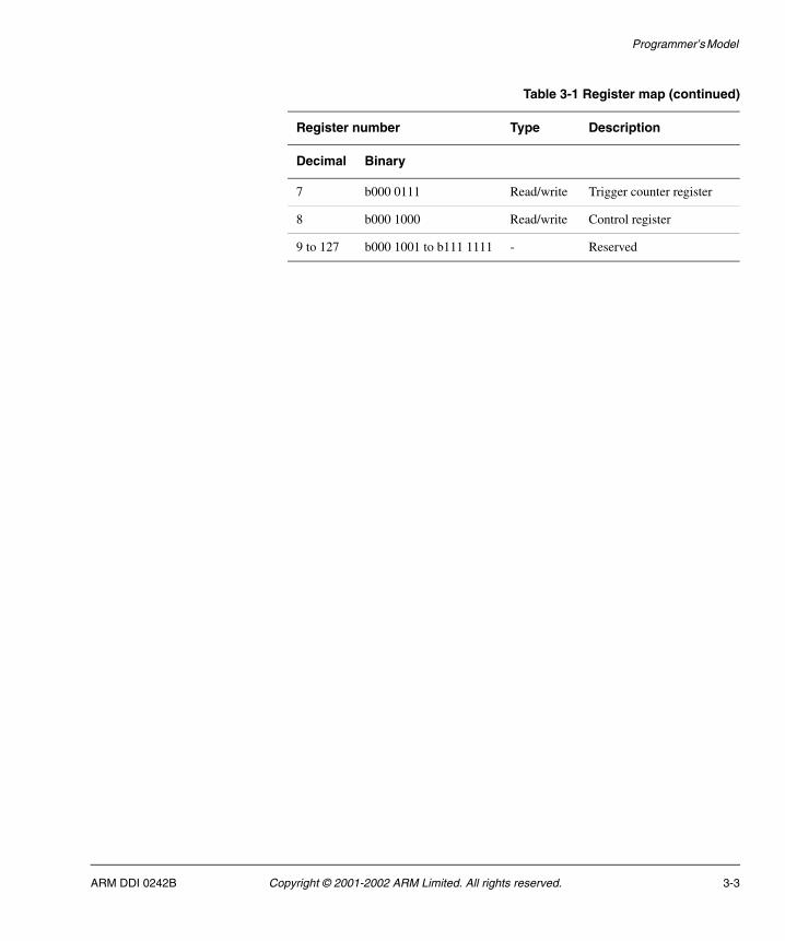
The ETB register map is shown in Table 3-1.
Table 3-1 Register map
Register number Type Description
Decimal Binary
0 b000 0000 Read only Identification register
1 b000 0001 Read only RAM depth register
2 b000 0010 Read only RAM width register
3 b000 0011 Read only Status register
4 b000 0100 Read only RAM data register
5 b000 0101 Read/write RAM read pointer register
6 b000 0110 Read/write RAM write pointer register
3-2 Copyright © 2001-2002 ARM Limited. All rights reserved. ARM DDI 0242B
Programmer’s Model
7 b000 0111 Read/write Trigger counter register
8 b000 1000 Read/write Control register
9 to 127 b000 1001 to b111 1111 - Reserved
Table 3-1 Register map (continued)
Register number Type Description
Decimal Binary
ARM DDI 0242B Copyright © 2001-2002 ARM Limited. All rights reserved. 3-3

Programmer’s Model
3.2 Register descriptions
This section describes the ETB registers:
• Identification, register 0
• RAM depth, register 1
• RAM width, register 2 on page 3-5
• Status, register 3 on page 3-5
• RAM data, register 4 on page 3-6
• RAM read pointer, register 5 on page 3-7
• RAM write pointer, register 6 on page 3-7
• Trigger counter, register 7 on page 3-8
• Control, register 8 on page 3-9.
3.2.1 Identification, register 0
The identification register enables the TAP controller to be identified by Multi-ICE, or any other run control device. It is a 32-bit register. The value of the ID register is set by a define TAP_ID_CODE, in the EtbDefs.v file. For the current implementation the ID value is 32’h1B900F0F.
3.2.2 RAM depth, register 1
The RAM depth register is a read-only register that indicates the number of addressable entries in the RAM to the trace tools. Register bit allocation is listed in Table 3-2.
Table 3-2 RAM depth register
Bitnumber
Name Type Function
31:0 RamDepth Read-only RAM data depth
This value is configurable in the RTL but must be fixed when the ETB is synthesized.
3-4 Copyright © 2001-2002 ARM Limited. All rights reserved. ARM DDI 0242B

Programmer’s Model
3.2.3 RAM width, register 2
This is a read-only register, that indicates the number of bits in each addressable entry in the RAM to the trace tools. Register bit allocation is listed in Table 3-3.
3.2.4 Status, register 3
The status register contains ETB status flags and can be read at any time. Register bit allocation is listed in Table 3-4.
Table 3-3 RAM width register
Bitnumber
Name Type Function
31:6 Reserved - -
5:0 RamWidth Read-only RAM data width
b100000=32-bit data
b011000=24-bit data
Table 3-4 Status register
Bitnumber
Name Type Function
31:4 Reserved - -
3 DFEmpty Read-only Data Formatter pipeline empty.
This bit is required because when tracing is disabled there might still be some trace data in the Data Formatter pipeline. This is drained within a few cycles after trace capture is disabled (see Control, register 8 on page 3-9). You can ensure that all trace data has been written to the buffer by waiting for this bit to be set.
2 AcqComp Read-only Acquisition complete
The acquisition complete flag indicates that the trigger counter is zero.
1 Triggered Read-only Triggered
The Triggered bit is set when a trigger packet (TR) has been observed, from the ETM.
0 Full Read-only RAM full
The flag indicates when the RAM write pointer has overflowed or wrapped around.
ARM DDI 0242B Copyright © 2001-2002 ARM Limited. All rights reserved. 3-5

Programmer’s Model
The status register is cleared on the cycle that trace capture is enabled, see Control, register 8 on page 3-9.
The recommended procedure for use of the tools is:
1. Program the ETB registers.
2. Enable tracing.
3. Wait until the AcqComp bit is set.
4. Disable tracing.
5. Wait until the DFEmpty bit is set.
6. Read the trace.
3.2.5 RAM data, register 4
While trace capture is disabled, reading the RAM data register returns the contents of the ETB SRAM location addressed by the RAM read pointer. Reading this register increments the RAM read pointer register and triggers a RAM access cycle. Register bit allocation is listed in Table 3-5.
Caution The RAM data register cannot be accessed while trace capture is enabled.
Table 3-5 RAM data register
Bitnumber
Name Type Function
31:24 Reserved - -
23:0 RamData Read-only RAM Data.
Returns the captured trace data.
3-6 Copyright © 2001-2002 ARM Limited. All rights reserved. ARM DDI 0242B
Programmer’s Model
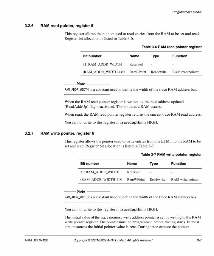
3.2.6 RAM read pointer, register 5
This register allows the pointer used to read entries from the RAM to be set and read. Register bit allocation is listed in Table 3-6.
Note RAM_ADDR_WIDTH is a constant used to define the width of the trace RAM address bus.
When the RAM read pointer register is written to, the read address updated (ReadAddrUp) flag is activated. This initiates a RAM access.
When read, the RAM read pointer register returns the current trace RAM read address.
You cannot write to this register if TraceCaptEn is HIGH.
3.2.7 RAM write pointer, register 6
This register allows the pointer used to write entries from the ETM into the RAM to be set and read. Register bit allocation is listed in Table 3-7.
Note RAM_ADDR_WIDTH is a constant used to define the width of the trace RAM address bus.
You cannot write to this register if TraceCaptEn is HIGH.
The initial value of the trace memory write address pointer is set by writing to the RAM write pointer register. The pointer must be programmed before tracing starts. In most circumstances the initial pointer value is zero. During trace capture the pointer
Table 3-6 RAM read pointer register
Bit number Name Type Function
31: RAM_ADDR_WIDTH Reserved - -
(RAM_ADDR_WIDTH-1):0 RamRPoint Read/write RAM read pointer
Table 3-7 RAM write pointer register
Bit number Name Type Function
31: RAM_ADDR_WIDTH Reserved - -
(RAM_ADDR_WIDTH-1):0 RamWPoint Read/write RAM write pointer
ARM DDI 0242B Copyright © 2001-2002 ARM Limited. All rights reserved. 3-7

Programmer’s Model
increments when the DataValid flag is asserted by the Data Formatter. When the RAM write pointer register value increments from its maximum value back to zero, the Full flag is set.
Reading the RAM write pointer register returns the current trace RAM write address. During trace capture, write pointer changes might be asynchronous. For example, if TCK is not related to the CPU clock, in this case the read back value is indeterminate. This register only returns the correct write pointer value when trace acquisition is stopped (when the AcqComp status bit is set or trace capture is disabled).
3.2.8 Trigger counter, register 7
This register disables writes to the trace RAM after a defined number of words have been stored, following the trigger event. The counter is used as follows:
Trace after The counter is set to a large value (slightly less than the number of entries in the RAM).
Trace before The counter is set to a small value.
Trace about The counter is set to half the size of the ETB.
Register bit allocation is listed in Table 3-8.
Note RAM_ADDR_WIDTH is a constant used to define the width of the trace RAM address bus.
When written, the value of the trigger counter is set. This register must be updated before trace capture is enabled, failure to do so can result in unexpected trace behavior.
Reading the trigger counter register samples the value of the trigger counter. During trace capture, the value of the counter can change at any time. Therefore if a read is performed asynchronously the returned value might be unreliable.
Table 3-8 Trigger count register
Bit number Name Type Function
31: RAM_ADDR_WIDTH Reserved - -
(RAM_ADDR_WIDTH-1):0 TrigCnt Read/write Trigger count.
The number of datawords written into the trace RAM following the trigger event is given by the equation:
Count = TrigCnt + 1
3-8 Copyright © 2001-2002 ARM Limited. All rights reserved. ARM DDI 0242B

Programmer’s Model
You cannot write to this register if TraceCaptEn is HIGH.
3.2.9 Control, register 8
The control register is used to enable/disable the trace capture using bit 0. Register bit allocation is listed in Table 3-9.
Control register bit 0 drives the TraceCaptEn signal.
When TraceCaptEn is set the ETB SRAM is in write mode. If a RAM data register read is attempted while TraceCaptEn is set then the contents of the SRAM are altered, resulting in the corruption of any stored trace data.
The ETB starts up from reset with the SoftwareCntl bit enabled. The value of this bit can only be changed through the TAP controller. It is cleared when the INTEST instruction is selected by the TAP controller and is set by writing a 1 as normal. While this bit is clear, all accesses to the register by the AHB interface are ignored.
Table 3-9 Control register
Bitnumber
Name Type Function
31:3 Reserved - -
2 SoftwareCntl Read/write (JTAG only) Controls software and hardware register access:
1 = Software register access
0 = JTAG register access
1 Demux Read/write Demultiplexed memory support:
1 = Demultiplexed support enabled
0 = Demultiplexed support disabled
0 TraceCaptEn Read/write Trace capture enable:
1 = Trace Capture is enabled
0 = Trace Capture is disabled
ARM DDI 0242B Copyright © 2001-2002 ARM Limited. All rights reserved. 3-9
Programmer’s Model
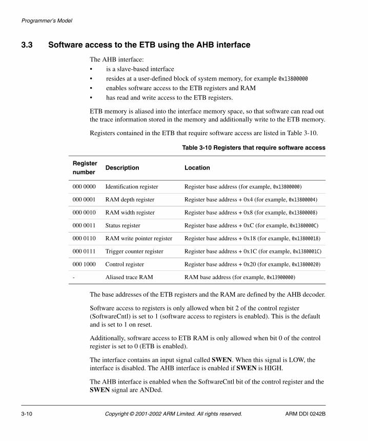
3.3 Software access to the ETB using the AHB interface
The AHB interface:
• is a slave-based interface
• resides at a user-defined block of system memory, for example 0x13800000
• enables software access to the ETB registers and RAM
• has read and write access to the ETB registers.
ETB memory is aliased into the interface memory space, so that software can read out the trace information stored in the memory and additionally write to the ETB memory.
Registers contained in the ETB that require software access are listed in Table 3-10.
The base addresses of the ETB registers and the RAM are defined by the AHB decoder.
Software access to registers is only allowed when bit 2 of the control register (SoftwareCntl) is set to 1 (software access to registers is enabled). This is the default and is set to 1 on reset.
Additionally, software access to ETB RAM is only allowed when bit 0 of the control register is set to 0 (ETB is enabled).
The interface contains an input signal called SWEN. When this signal is LOW, the interface is disabled. The AHB interface is enabled if SWEN is HIGH.
The AHB interface is enabled when the SoftwareCntl bit of the control register and the SWEN signal are ANDed.
Table 3-10 Registers that require software access
Registernumber
Description Location
000 0000 Identification register Register base address (for example, 0x13800000)
000 0001 RAM depth register Register base address + 0x4 (for example, 0x13800004)
000 0010 RAM width register Register base address + 0x8 (for example, 0x13800008)
000 0011 Status register Register base address + 0xC (for example, 0x1380000C)
000 0110 RAM write pointer register Register base address + 0x18 (for example, 0x13800018)
000 0111 Trigger counter register Register base address + 0x1C (for example, 0x1380001C)
000 1000 Control register Register base address + 0x20 (for example, 0x13800020)
- Aliased trace RAM RAM base address (for example, 0x13900000)
3-10 Copyright © 2001-2002 ARM Limited. All rights reserved. ARM DDI 0242B

Programmer’s Model
The ETB registers and RAM accesses are controlled by separate read/write ports and each has their own separate HSEL input. This enables the ETB RAM to share the address space with main memory. SWEN and bit 2 of the control register control the memory that is part of the memory map at a certain time.
3.3.1 Restrictions on use of the AHB interface
The AHB interface can be used for two purposes:
• to read trace data captured by the ETB from software
• as system memory when tracing is not required.
When using the AHB interface to read trace data, the following are not permitted:
• byte or halfword accesses
• unaligned accesses
• multi-word accesses (such as LDM or STM).
Only aligned, single word accesses are permitted.
Use of the AHB interface as system memory requires careful system design to ensure that the memory is not required for system use when tracing is required. If you wish to use the AHB interface for this purpose, you must ensure the following:
• the memory supports byte writes (see the Embedded Trace Buffer Implementation Guide)
• if connected to a 64 bit AHB bus, 64 bit operations are supported see Connecting the ETB in a 64-bit AHB system on page B-8).
This is to ensure that all ARM load/store instructions are supported.
ARM DDI 0242B Copyright © 2001-2002 ARM Limited. All rights reserved. 3-11

Programmer’s Model
3.4 Potential limitations
In ETMv1, a periodic address is broadcast by the ETM at intervals of between 1000 and 1500 cycles as defined by the ETM Specification. For an off-chip buffer of around 256K-cycles this is fine, but for depths of less than1K-cycles, when using 16-bit trace packets, it is possible that a large part of the buffer is wasted because of the lack of a synchronization point. In rare cases, there might be no synchronization points stored.
ARM Limited recommends a minimum depth of 1K-cycles, this is equal to:
• 3Kb if RAM_BIT_WIDTH=24
• 4Kb if RAM_BIT_WIDTH=32.
ETMv2 and generic trace port interface devices allow the synchronization broadcast interval to be configurable, so this is not a issue with these macrocells.
Periodic broadcast is not a problem when filtering the instruction trace because when tracing starts, a full address is broadcast. Filtering is usually required to improve memory usage when using a small buffer.
3-12 Copyright © 2001-2002 ARM Limited. All rights reserved. ARM DDI 0242B

Chapter 4 Timing Requirements
The timing requirements for the ETB interfaces are defined in this chapter. It contains the following sections:
• AHB interface on page 4-2
• CLK domain on page 4-4
• IEEE1149.1 Interface on page 4-6.
ARM DDI 0242B Copyright © 2001-2002 ARM Limited. All rights reserved. 4-1

Timing Requirements
4.1 AHB interface
The timing for the AHB interface signals are shown in Figure 4-1.
Figure 4-1 AHB interface signals
The timing requirements for the AHB interface are listed in Table 4-1. All figures are expressed as percentages of the HCLK period at maximum operating frequency.
Note A 0% figure in Table 4-1 indicates the hold time to clock edge plus the maximum clock skew for internal clock buffering.
Tihhresetn
Tishresetn
Tihhcon
Tishcon
Tihhdata
Tishdata
Tohhcon
Tovhcon
Tohhdata
Tovhdata
HADDR,
HWDATA
HRDATAMEM
HCLK
HRESP,
HREADYMEM
HWRITE,
HTRANS,
HSIZE,
HREADY,
HSELREG,
HSELMEM
HRESETn
Table 4-1 AHB interface timing requirements
Parameter Description Max Min
Tovhdata Rising HCLK to HRDATAMEM valid 40% -
Tohhdata HRDATAMEM hold time from HCLK rising - >0%
Tovhcon Rising HCLK to AHB control outputs valid 40% -
Tohhcon AHB control outputs hold time from HCLK rising - >0%
4-2 Copyright © 2001-2002 ARM Limited. All rights reserved. ARM DDI 0242B

Timing Requirements
Tishdata AHB data inputs setup to rising HCLK - 30%
Tihhdata AHB data inputs hold from rising HCLK - 0%
Tishcon AHB control inputs setup to rising HCLK - 30%
Tihhcon AHB control inputs hold from rising HCLK - 0%
Tishresetn HRESETn input setup to rising HCLK - 30%
Tihhresetn HRESETn input hold from rising HCLK - 0%
Table 4-1 AHB interface timing requirements (continued)
Parameter Description Max Min
ARM DDI 0242B Copyright © 2001-2002 ARM Limited. All rights reserved. 4-3

Timing Requirements
4.2 CLK domain
The timing for the CLK domain signals are shown in Figure 4-2.
Figure 4-2 CLK domain signals
The timing requirements for the CLK domain signals are listed in Table 4-2. All figures are expressed as percentages of the CLK period at maximum operating frequency.
Note A 0% figure in Table 4-2 indicates the hold time to clock edge plus the maximum clock skew for internal clock buffering.
Tihnreset
Tisnreset
Tihbtrans
Tisbtrans
Tihetmtrans
Tisetmtrans
Tohbdtrans
Tovbdtrans
Tovctrans
Tohctrans
TRACEOUTPUT
TRACEVALID,
TRIGGER
ACQCOMP,
FULL
CLK
BISTDO
BISTCS,
BISTDI,
BISTA,
BISTWEBUS,
BISTWE,
BISTEN
nRESET
Table 4-2 CLK domain timing requirements
Parameter Description Max Min
Tovctrans Rising CLK to CLK domain outputs valid 40% -
Tohctrans CLK domain outputs hold time from CLK rising >0%
Tovbdtrans Rising CLK to BISTDO output valid 60% -
Tohbdtrans BISTDO output hold time from CLK rising - >0%
4-4 Copyright © 2001-2002 ARM Limited. All rights reserved. ARM DDI 0242B

Timing Requirements
Tisbtrans BIST inputs setup to rising CLK - 40%
Tihbtrans BIST inputs hold from rising CLK - 0%
Tisetmtrans ETM interface inputs setup to rising CLK - 40%
Tihetmtrans ETM interface inputs hold from rising CLK - 0%
Tisnreset nRESET input setup to rising CLK - 40%
Tihnreset nRESET input hold from rising CLK - 0%
Tovctrans Rising CLK to CLK domain outputs valid 40% -
Tohctrans CLK domain outputs hold time from CLK rising - >0%
Table 4-2 CLK domain timing requirements (continued)
Parameter Description Max Min
ARM DDI 0242B Copyright © 2001-2002 ARM Limited. All rights reserved. 4-5

Timing Requirements
4.3 IEEE1149.1 Interface
The IEEE1149.1 interface signals are shown in Figure 4-3.
Figure 4-3 IEEE1149.1 interface signals
The timing requirements for the IEEE1149.1 interface trace data signals are listed in Table 4-3. All figures are expressed as percentages of the TCK period at maximum operating frequency.
Note A 0% figure in Table 4-3 indicates the hold time to clock edge plus the maximum clock skew for internal clock buffering.
Tisntrst
Tisttrans
Tihntrst
Tihttrans
Tohttrans
Tovttrans
TDI,
TMS,
TCKEN
TDO
TCK
nTRST
Table 4-3 IEEE1149.1 interface timing requirements
Parameter Description Max Min
Tovttrans Rising TCK to TDO output valid 40% -
Tohttrans TDO output hold time from TCK rising - >0%
Tisttrans JTAG inputs setup to rising CLK - 40%
Tihttrans JTAG inputs hold from rising HCLK - 0%
Tisntrst nTRST input setup to rising CLK - 40%
Tihntrst nTRST input hold from rising HCLK - 0%
4-6 Copyright © 2001-2002 ARM Limited. All rights reserved. ARM DDI 0242B

Appendix A Signal Descriptions
This appendix describes the ETB input and output signals. It contains the following sections:
• Signal properties and requirements on page A-2
• Signal descriptions on page A-3.
ARM DDI 0242B Copyright © 2001-2002 ARM Limited. All rights reserved. A-1
Signal Descriptions
A.1 Signal properties and requirements
To ensure ease of integration of the ETB into embedded applications, and to simplify synthesis flow, the following design techniques have been used:
• a single rising edge clock times all activity
• all signals and buses are unidirectional
• all inputs are required to be synchronous to the relevant clock (CLK, TCK, or HCLK).
These techniques simplify the definition of the top-level ETB signals because all outputs change from the rising edge and all inputs are sampled with the rising edge of the clock. In addition, all signals are either input or output only. Bidirectional signals are not used.
Note You must use external logic to synchronize asynchronous signals (for example, interrupt sources) before applying them to the ETB.
A-2 Copyright © 2001-2002 ARM Limited. All rights reserved. ARM DDI 0242B

Signal Descriptions
A.2 Signal descriptions
The ETB input and output signals are listed in Table A-1.
Table A-1 Signal descriptions
Signal NameClockdomain
Type Description
BISTA CLK Input Address Bus for external BIST controller (active when BISTEN is HIGH)
BISTCS CLK Input Active HIGH chip select for external BIST controller (active when BISTEN is HIGH)
BISTDI[(RAM_BIT_WIDTH-1:0] CLK Input Write data bus for external BIST controller (active when BISTEN is HIGH)
BISTEN CLK Input Enable signal for external BIST controller
BISTWE CLK Input Active HIGH write enable for external BIST controller (active when BISTEN is HIGH). This is only active for RAM that does not support byte writes
BISTWEBUS CLK Input Active HIGH write enable bus for external BIST controller (active when BISTEN is HIGH). This is only active for RAM that supports byte writes
CLK - Input This clock times all operations in the Trace Buffer
HADDR[31:0] HCLK Input The 32-bit AHB system address bus
HCLK - Input AHB system bus clock
HREADY HCLK Input When HIGH indicates that a transfer has finished on the AHB bus
HRESETn HCLK Input AHB system bus reset
HSELMEM HCLK Input
HSELREG HCLK Input Indicates that the ETB registers have been selected for an AHB transfer
HSIZE[2:0] HCLK Input Indicates the size of the AHB transfer
ARM DDI 0242B Copyright © 2001-2002 ARM Limited. All rights reserved. A-3

Signal Descriptions
HTRANS[1:0] HCLK Input Indicates the type of AHB transfer:
00 = IDLE
01 = NONSEQ
11 = SEQ
HWDATA[31:0] HCLK Input The 32-bit AHB write data bus
HWRITE HCLK Input When HIGH indicates an AHB write transfer.
When LOW indicates an AHB read transfer
nRESET CLK Input Active LOW ETB reset
nTRST TCK Input Active LOW test reset
PORTSIZE[2:0] CLK Input Indicates currently selected port size in use on the TRACEPKT[15:0] bus
PROTOCOL[1:0] CLK Input Indicates the currently selected ETM protocol
SBYPASS CLK Input Indicates that HCLK and CLK are synchronous, so the synchronizing logic can be bypassed
SWEN - Input When LOW disables the ETB
TCK - Input Test clock
TCKEN TCK Input Test clock enable
TDI TCK Input Test data input
TMS TCK Input Test mode select
TRACEOUTPUT [(RAM_BIT_WIDTH-1:0] CLK Input Trace information from the ETM
TRACEVALID CLK Input Indicates that the current trace information on TRACEOUTPUT is valid
TRIGGER CLK Input Indicates that an ETM trigger has occurred
ACQCOMPa CLK Output When HIGH indicates that trace acquisition is complete
BISTDO[(RAM_BIT_WIDTH-1:0] CLK Output Read data bus for external BIST controller (active when BISTEN is HIGH)
Table A-1 Signal descriptions (continued)
Signal NameClockdomain
Type Description
A-4 Copyright © 2001-2002 ARM Limited. All rights reserved. ARM DDI 0242B

Signal Descriptions
FULLa CLK Output When HIGH indicates that the ETB RAM has overflowed
HRDATAMEM [31:0] HCLK Output The 32-bit AHB read data bus
HREADYMEM HCLK Output When LOW indicates that the ETB is carrying out an AHB transfer
HRESPMEM[1:0] HCLK Output Memory-mapped peripheral AHB transfer response. Provides additional information on the transfer status:
00 = OKAY
01 = ERROR
10 = RETRY
11 = SPLIT
TDO TCK Output Test data output
a. Can be left unconnected during normal operation.
Table A-1 Signal descriptions (continued)
Signal NameClockdomain
Type Description
ARM DDI 0242B Copyright © 2001-2002 ARM Limited. All rights reserved. A-5

Signal Descriptions
A-6 Copyright © 2001-2002 ARM Limited. All rights reserved. ARM DDI 0242B

Appendix B Integrating the ETB
This section describes how to integrate the ETB if you are not using a MIK. It contains the following sections:
• Connection guide on page B-2
• Integrating the ETB with an ETMv1 device on page B-3
• Integrating the ETB with an ETMv2 device on page B-5
• Integrating the ETB with a generic trace port interface device on page B-7
• Connecting the ETB in a 64-bit AHB system on page B-8.
ARM DDI 0242B Copyright © 2001-2002 ARM Limited. All rights reserved. B-1

Integrating the ETB
B.1 Connection guide
Table B-1 lists the relevant ETB signals and how to use and connect them.
Table B-1 ETB connection guide
Signal Connection information
SWEN If the AHB interface is to be used to access the ETB registers and the ETB RAM, then this must be tied HIGH. Otherwise it must be tied LOW.
ACQCOMP This is a status signal from the ETB that can be used to control on-chip logic. For example, ACQCOMP can be used to generate an interrupt request to the ARM processor in the system to indicate that the ETB is finished collecting trace information.
FULL This is a status signal from the ETB that can be used to control on-chip logic. For example, FULL can be used to generate an interrupt request to the ARM processor in the system to indicate that the ETB RAM is full.
SBYPASS If HCLK and CLK are synchronous then this signal must be tied HIGH so that the synchronization logic between the HCLK and CLK domain is bypassed. Otherwise this must be tied LOW.
HCLK If HCLK and CLK are synchronous then HCLK can be generated from CLK and HCLKEN if it is not already available. The following verilog code demonstrates this:always @(CLK or HCLKEN) if (!CLK) HCLKENlat <= HCLKEN;
assign HCLK = CLK & HCLKENlat;
HSELMEM This is an AHB select signal to indicate that an access to the ETB registers is being initiated. This must be generated in the ASIC AHB decode and has a separate memory map to the ETB RAM.
HSELREG This is an AHB select signal to indicate that an access to the ETB RAM is being initiated. This must be generated in the ASIC AHB decoder and has a separate memory map to the ETB registers.
B-2 Copyright © 2001-2002 ARM Limited. All rights reserved. ARM DDI 0242B

Integrating the ETB
B.2 Integrating the ETB with an ETMv1 device
See ETMv1 architecture data formats on page 2-9 for information about the connection of the TRACEOUTPUT signal.
Connection of the ETB to an ETMv1 device is described in:
• Normal mode
• Demultiplexed mode.
B.2.1 Normal mode
Use the connection scheme listed in Table B-2 to connect the ETB to an ETMv1 device for use in normal mode.
B.2.2 Demultiplexed mode
Use the connection scheme listed in Table B-3 to connect the ETB to an ETMv1 device for use in demultiplexed mode.
Table B-2 ETB to ETMv1 connections for normal mode
ETB signal Connection
TRACEOUTPUT[RAM_BIT_WIDTH-1:20] GND
TRACEOUTPUT[19] TRACESYNC
TRACEOUTPUT[18:3] TRACEPKT[15:0]
TRACEOUTPUT[2:0] PIPESTAT[2:0]
Table B-3 ETB to ETMv1 connections for demultiplexed mode
ETB signal Connection
TRACEOUTPUT[RAM_BIT_WIDTH-1:24] GND
TRACEOUTPUT[23] TRACESYNCA
TRACEOUTPUT[22:15] TRACEPKTA[7:0]
TRACEOUTPUT[14:12] PIPESTATA[2:0]
TRACEOUTPUT[11] TRACESYNCB
TRACEOUTPUT[10:3] TRACEPKTB[7:0]
TRACEOUTPUT[2:0] PIPESTATB[2:0]
ARM DDI 0242B Copyright © 2001-2002 ARM Limited. All rights reserved. B-3
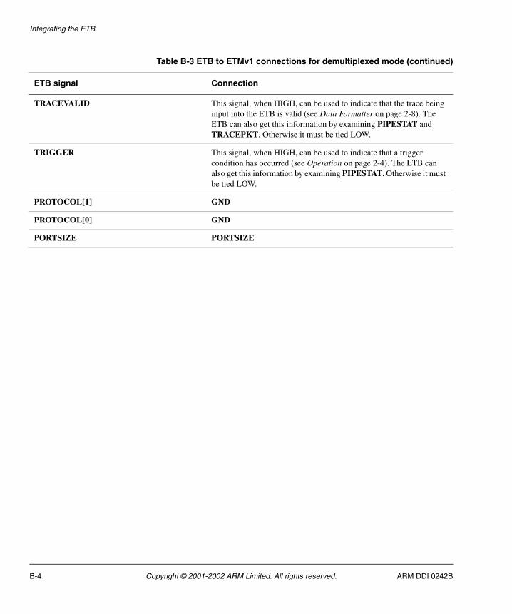
Integrating the ETB
TRACEVALID This signal, when HIGH, can be used to indicate that the trace being input into the ETB is valid (see Data Formatter on page 2-8). The ETB can also get this information by examining PIPESTAT and TRACEPKT. Otherwise it must be tied LOW.
TRIGGER This signal, when HIGH, can be used to indicate that a trigger condition has occurred (see Operation on page 2-4). The ETB can also get this information by examining PIPESTAT. Otherwise it must be tied LOW.
PROTOCOL[1] GND
PROTOCOL[0] GND
PORTSIZE PORTSIZE
Table B-3 ETB to ETMv1 connections for demultiplexed mode (continued)
ETB signal Connection
B-4 Copyright © 2001-2002 ARM Limited. All rights reserved. ARM DDI 0242B

Integrating the ETB
B.3 Integrating the ETB with an ETMv2 device
See ETMv1 architecture data formats on page 2-9 for information about the connection of the TRACEOUTPUT signal.
Connection of the ETB to an ETMv1 device is described in:
• Normal mode
• Demultiplexed mode.
B.3.1 Normal mode
Use the connection scheme listed in Table B-4 to connect the ETB to an ETMv2 device for use in normal mode.
B.3.2 Demultiplexed mode
Use the connection scheme listed in Table B-3 on page B-3 to connect the ETB to an ETMv1 device for use in demultiplexed mode.
Table B-4 ETB to ETMv2 connections for normal mode
ETB signal Connection
TRACEOUTPUT[RAM_BIT_WIDTH-1:20] GND
TRACEOUTPUT[19] TRACESYNC
TRACEOUTPUT[18:3] TRACEPKT[15:0]
TRACEOUTPUT[2:0] PIPESTAT[2:0]
Table B-5 ETB to ETMv2 connections for demultiplexed mode
ETB signal Connection
TRACEOUTPUT[RAM_BIT_WIDTH-1:24] GND
TRACEOUTPUT[23] PIPESTATA[3]
TRACEOUTPUT[22:15] TRACEPKTA[7:0]
TRACEOUTPUT[14:12] PIPESTATA[2:0]
TRACEOUTPUT[11] PIPESTATB[3]
TRACEOUTPUT[10:3] TRACEPKTB[7:0]
TRACEOUTPUT[2:0] PIPESTATB[2:0]
ARM DDI 0242B Copyright © 2001-2002 ARM Limited. All rights reserved. B-5

Integrating the ETB
TRACEVALID This signal, when HIGH, can be used to indicate that the trace being input into the ETB is valid (see Data Formatter on page 2-8). The ETB can also get this information by examining PIPESTAT and TRACEPKT. Otherwise it must be tied LOW.
TRIGGER This signal, when HIGH, can be used to indicate that a trigger condition has occurred (see Operation on page 2-4). The ETB can also get this information by examining PIPESTAT. Otherwise it must be tied LOW.
PROTOCOL[1] GND
PROTOCOL[0] VCC
PORTSIZE PORTSIZE
Table B-5 ETB to ETMv2 connections for demultiplexed mode (continued)
ETB signal Connection
B-6 Copyright © 2001-2002 ARM Limited. All rights reserved. ARM DDI 0242B

Integrating the ETB
B.4 Integrating the ETB with a generic trace port interface device
Use the connection scheme listed in Table B-6 to connect the ETB to a generic trace port interface device.
Table B-6 ETB to generic trace port interface connections
ETB signal Connection
TRACEOUTPUT[RAM_BIT_WIDTH-1:0] TRACEDATA[RAM_BIT_WIDTH-1:0]
TRACEOUTPUT[23] PIPESTATA[3]
TRACEOUTPUT[22:15] TRACEPKTA[7:0]
TRACEOUTPUT[14:12] PIPESTATA[2:0]
TRACEOUTPUT[11] PIPESTATB[3]
TRACEOUTPUT[10:3] TRACEPKTB[7:0]
TRACEOUTPUT[2:0] PIPESTATB[2:0]
TRACEVALID TRACEVALID
TRIGGER TRIGGER
PROTOCOL[1] VCC
PROTOCOL[0] GND
PORTSIZE GND
ARM DDI 0242B Copyright © 2001-2002 ARM Limited. All rights reserved. B-7
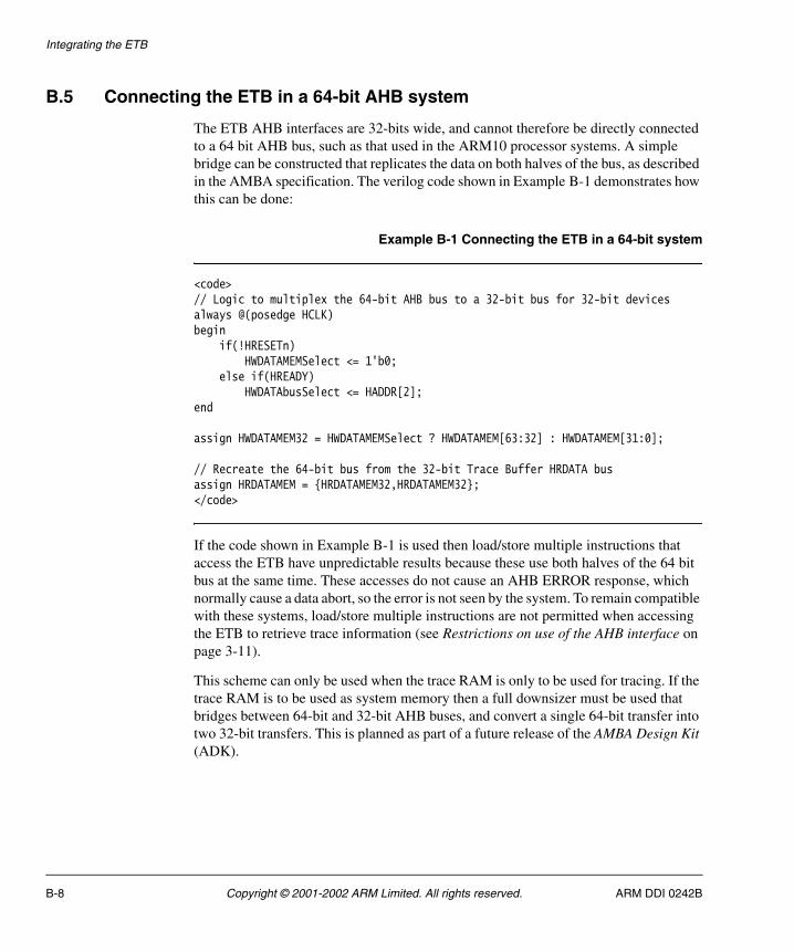
Integrating the ETB
B.5 Connecting the ETB in a 64-bit AHB system
The ETB AHB interfaces are 32-bits wide, and cannot therefore be directly connected to a 64 bit AHB bus, such as that used in the ARM10 processor systems. A simple bridge can be constructed that replicates the data on both halves of the bus, as described in the AMBA specification. The verilog code shown in Example B-1 demonstrates how this can be done:
Example B-1 Connecting the ETB in a 64-bit system
<code>// Logic to multiplex the 64-bit AHB bus to a 32-bit bus for 32-bit devicesalways @(posedge HCLK)begin if(!HRESETn) HWDATAMEMSelect <= 1'b0; else if(HREADY) HWDATAbusSelect <= HADDR[2];end
assign HWDATAMEM32 = HWDATAMEMSelect ? HWDATAMEM[63:32] : HWDATAMEM[31:0];
// Recreate the 64-bit bus from the 32-bit Trace Buffer HRDATA busassign HRDATAMEM = {HRDATAMEM32,HRDATAMEM32};</code>
If the code shown in Example B-1 is used then load/store multiple instructions that access the ETB have unpredictable results because these use both halves of the 64 bit bus at the same time. These accesses do not cause an AHB ERROR response, which normally cause a data abort, so the error is not seen by the system. To remain compatible with these systems, load/store multiple instructions are not permitted when accessing the ETB to retrieve trace information (see Restrictions on use of the AHB interface on page 3-11).
This scheme can only be used when the trace RAM is only to be used for tracing. If the trace RAM is to be used as system memory then a full downsizer must be used that bridges between 64-bit and 32-bit AHB buses, and convert a single 64-bit transfer into two 32-bit transfers. This is planned as part of a future release of the AMBA Design Kit (ADK).
B-8 Copyright © 2001-2002 ARM Limited. All rights reserved. ARM DDI 0242B

Glossary
This glossary describes some of the terms used in this manual. Where terms can have several meanings, the meaning presented here is intended.
Advanced microcontroller bus architectureThe ARM open standard for on-chip buses. AHB is specified in this standard.
AMBA See Advanced microcontroller bus architecture.
Byte An eight-bit data item.
Clock gating Gating a clock signal for a macrocell with a control signal, and using the modified clock that results to control the operating state of the macrocell.
Debugger A debugging system which includes a program, used to detect, locate, and correct software faults, together with custom hardware that supports software debugging.
Embedded trace macrocellA hardware macrocell which, when connected to a processor core, outputs instruction and data trace information on a trace port.
ETM See Embedded trace macrocell
Halfword A 16-bit data item.
JTAG See Joint test action group
ARM DDI 0242B Copyright © 2001-2002 ARM Limited. All rights reserved. Glossary-1

Glossary
Joint test action groupThe name of the organization that developed standard IEEE 1149.1. This standard defines a boundary-scan architecture used for in-circuit testing of integrated circuit devices. It is commonly known by the initials JTAG.
Macrocell A complex logic block with a defined interface and behavior. A typical VLSI system comprises several macrocells (such as an ETM9 and a memory block) plus application-specific logic.
Reserved A field in a control register or instruction format is reserved if the field is to be defined by the implementation, or produces UNPREDICTABLE results if the contents of the field are set as specified. These fields are reserved for use in future extensions of the architecture or are implementation-specific. All reserved bits not used by the implementation must be written as zero and will be read as zero.
TAP See Test access port
Test access port The collection of four mandatory and one optional terminals that form the input and output and control interface to a JTAG boundary-scan architecture. The mandatory terminals are TDI, TDO, TMS, and TCK. The optional terminal is nTRST.
TPA See Trace port analyzer.
Trace driver A target that controls a piece of trace hardware. That is, the trigger macrocell, trace macrocell and trace capture tool.
Trace hardware A term for a device that contains an ETM.
Trace port analyzer The trace port analyzer is an external hardware device that stores the information from the trace port, for example a logic analyzer or a low-cost collection unit. The debug tools retrieve data from the analyzer, reconstruct an historical view of the processor's activity including data accesses, as well as configuring the macrocell using the JTAG port. Powerful user-definable filters allow you to limit the amount of information captured in search of a bug, reducing upload time from the trace port analyzer.
UNPREDICTABLE For reads, the data returned when reading from this location is unpredictable. It can have any value. For writes, writing to this location causes unpredictable behavior, or an unpredictable change in device configuration. UNPREDICTABLE instructions must not halt or hang the processor, or any part of the system.
Word A 32-bit data item.
Glossary-2 Copyright © 2001-2002 ARM Limited. All rights reserved. ARM DDI 0242B

Index
AAC timing
AHB interface 4-2CLK domain 4-4IEEE1149 interface 4-6
Address generation 2-18AHB
connecting to 64-bit B-8restrictions on use 3-11software access 3-10
AHB interface timingsignals 4-2
BBoundary scan 1-3
CCLK domain
AC tming 4-4CLK domain signals 4-4Clock domains 2-24Clocks 2-24Configurability 2-2Control logic 2-6Control register 3-9
DData formatter 2-8Debug implementation 1-2
EEmbeddedICE 1-3ETB module 2-3ETM 1-3
version compatibility 2-3versions 2-9versions and variants 1-4
ETMv1architecture data formats 2-9integrating B-3
demultiplexed B-3normal B-3
RAM data word definition 2-11TRACEOUTPUT pin connections
2-98-bit trace port connections 2-10
ETMv2architecture data formats 2-11integrating
demultiplexed B-5normal B-5
RAM data word definition 2-14TRACEOUTPUT pin connections
2-128-bit trace port connections 2-12
GGeneric trace port interface
ARM DDI 0242B Copyright © 2001-2002 ARM Limited. All rights reserved. Index-1

Index
architecture data formats 2-15integrating B-7RAM data word definition 2-15TRACEOUTPUT pin connections
2-15
IIdentification register 3-4IEEE1149.1
signals 4-6Instruction register 2-21
public instructions 2-21Integrating
ETMv1 B-3demultiplexed B-3normal B-3
ETMv2demultiplexed B-5normal B-5
generic race port interface B-7signals B-2
Interfacesprimary 2-2
JJTAG 1-3
NnRESET synchronizer 2-32
OOperation 2-4
PPacket width 2-16Periodic address 3-12PORTSIZE encoding 2-16Primary interfaces 2-2
RRAM data register 3-6RAM depth register 3-4RAM read pointer register 3-7RAM width register 3-5RAM write pointer register 3-7Read address generation 2-18Read transfer
asynchronous 2-25synchronous 2-28
Register fields 3-2Register map 3-2Registers 3-4
control 3-9identification 3-4RAM data 3-6RAM depth 3-4RAM read pointer 3-7RAM width 3-5RAM write pointer 3-7software access 3-10status 3-5trigger counter 3-8
Resets 2-31
SSignal descriptions A-2, A-3Signal properties and requirements A-2Software
access to ETB 3-10Software read cycle
asynchronous 2-27synchronous 2-28
Software write cycleasynchronous 2-30synchronous 2-31
Status register 3-5Supported public instructions 2-21
TTAP controller 2-20Test data registers
bypass 2-20scan chain 0 2-21
Trace capture operation 2-6Trace RAM interface 2-22
read access 2-22signals 2-22write access 2-23
Trace read operation 2-7TrgDelayCounter 2-17Trigger counter register 3-8Trigger delay counter 2-17
WWrite address generation 2-18Write transfer
asynchronous 2-28synchronous 2-30
Index-2 Copyright © 2001-2002 ARM Limited. All rights reserved. ARM DDI 0242B