embedding reliable numerical analysis … reliable numerical analysis capabilities into an...
TRANSCRIPT
Embedding Reliable Numerical AnalysisCapabilities into an Enterprise Wide
Information System
Ottmar Klaas∗ and Mark S. ShephardScientific Computation Research Center
Rensselaer Polytechnic InstituteTroy, New York 12180-3590
USA
July 18, 2000
Abstract
A simulation environment to support engineering design embeddedin an enterprise wide information system is presented. The environ-ment consists of a set of structures and managers housing the problemdefinition, and tools controlling the construction of the simulation do-main, the simulation itself, and the interaction with the product datamanagement system. The interaction with the product data man-agement system is facilitated by providing a relational database rep-resentation of the simulation attributes (loads, boundary conditionsetc.).
Keywords. Geometry-based simulation; Engineering Design; ProductData Management; Computational Mechanics;
∗Correspondence and offprint requests to: O. Klaas, Scientific Computation ResearchCenter, CII 7311, Rensselaer Polytechnic Institute, Troy, NY 12180-3590, USA. email:[email protected]
1
1 Introduction
Companies have long realized that the integration of their information sys-tems is key to gaining and maintaining a competitive advantage. The datastored in electronic form in information systems is a valuable asset to a com-pany, and proper management of that data is needed to make use of it ina cost effective and profitable manner. This becomes paramount in todayswork environment, where design, engineering, manufacturing, and corporatefunctions are spread out around the globe, and fast and reliable access todata is needed to further streamline the product development in the searchfor improved product quality, accelerated time to market, and lower newproduct introduction costs.
Historically, advanced numerical simulation processes have not been wellintegrated into the information systems of a company. Efforts to bring sim-ulation into the engineering design/manufacturing process have focused onindividual capabilities which operate only on data descriptions natural tothe specific operation to be performed rather than tying processes togetherthrough product data management and workflow systems. The effective useof numerical simulation in product design requires a shift from individualpoint solutions to the effective handling of data, i.e. its representation, shar-ing and processing, through the application of automated simulation tools.To meet this goal the automated simulation environment must interact seam-lessly with product data management and workflow systems to execute thesimulations in a reliable fashion. Appropriate information control structures,and model tracking and modification processes are needed to execute the fullrange of idealization processes associated with a numerical analysis processand to communicate the results back to the design process.
In the first part of this paper we will present the information technolo-gies needed for the integration of a simulation environment into the de-sign/manufacturing process. In the second part we will look into the storageof problem definition data in a product data management system as one ofthe key features enabling the integration of numerical simulation and de-sign/manufacturing.
2
2 Geometry-Based Simulation and its Infor-
mation Technologies Needs
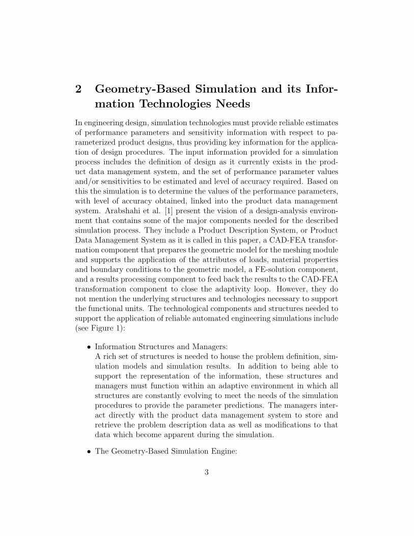
In engineering design, simulation technologies must provide reliable estimatesof performance parameters and sensitivity information with respect to pa-rameterized product designs, thus providing key information for the applica-tion of design procedures. The input information provided for a simulationprocess includes the definition of design as it currently exists in the prod-uct data management system, and the set of performance parameter valuesand/or sensitivities to be estimated and level of accuracy required. Based onthis the simulation is to determine the values of the performance parameters,with level of accuracy obtained, linked into the product data managementsystem. Arabshahi et al. [1] present the vision of a design-analysis environ-ment that contains some of the major components needed for the describedsimulation process. They include a Product Description System, or ProductData Management System as it is called in this paper, a CAD-FEA transfor-mation component that prepares the geometric model for the meshing moduleand supports the application of the attributes of loads, material propertiesand boundary conditions to the geometric model, a FE-solution component,and a results processing component to feed back the results to the CAD-FEAtransformation component to close the adaptivity loop. However, they donot mention the underlying structures and technologies necessary to supportthe functional units. The technological components and structures needed tosupport the application of reliable automated engineering simulations include(see Figure 1):
• Information Structures and Managers:A rich set of structures is needed to house the problem definition, sim-ulation models and simulation results. In addition to being able tosupport the representation of the information, these structures andmanagers must function within an adaptive environment in which allstructures are constantly evolving to meet the needs of the simulationprocedures to provide the parameter predictions. The managers inter-act directly with the product data management system to store andretrieve the problem description data as well as modifications to thatdata which become apparent during the simulation.
• The Geometry-Based Simulation Engine:
3
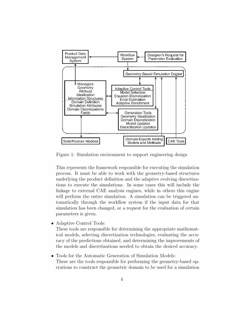
Figure 1: Simulation environment to support engineering design
This represents the framework responsible for executing the simulationprocess. It must be able to work with the geometry-based structuresunderlying the product definition and the adaptive evolving discretiza-tions to execute the simulations. In some cases this will include thelinkage to external CAE analysis engines, while in others this enginewill perform the entire simulation. A simulation can be triggered au-tomatically through the workflow system if the input data for thatsimulation has been changed, or a request for the evaluation of certainparameters is given.
• Adaptive Control Tools:These tools are responsible for determining the appropriate mathemat-ical models, selecting discretization technologies, evaluating the accu-racy of the predictions obtained, and determining the improvements ofthe models and discretizations needed to obtain the desired accuracy.
• Tools for the Automatic Generation of Simulation Models:These are the tools responsible for performing the geometry-based op-erations to construct the geometric domain to be used for a simulation
4
from the product definition, performing domain discretization, and up-dating the simulation models and discretizations as dictated by thesimulation process.
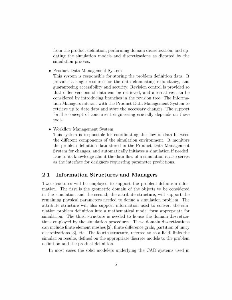
• Product Data Management SystemThis system is responsible for storing the problem definition data. Itprovides a single resource for the data eliminating redundancy, andguaranteeing accessibility and security. Revision control is provided sothat older versions of data can be retrieved, and alternatives can beconsidered by introducing branches in the revision tree. The Informa-tion Managers interact with the Product Data Management System toretrieve up to date data and store the necessary changes. The supportfor the concept of concurrent engineering crucially depends on thesetools.
• Workflow Management SystemThis system is responsible for coordinating the flow of data betweenthe different components of the simulation environment. It monitorsthe problem definition data stored in the Product Data ManagementSystem for changes, and automatically initiates a simulation if needed.Due to its knowledge about the data flow of a simulation it also servesas the interface for designers requesting parameter predictions.
2.1 Information Structures and Managers
Two structures will be employed to support the problem definition infor-mation. The first is the geometric domain of the objects to be consideredin the simulation and the second, the attribute structure, will support theremaining physical parameters needed to define a simulation problem. Theattribute structure will also support information used to convert the sim-ulation problem definition into a mathematical model form appropriate forsimulation. The third structure is needed to house the domain discretiza-tions employed by the simulation procedures. These domain discretizationscan include finite element meshes [2], finite difference grids, partition of unitydiscretizations [3], etc. The fourth structure, referred to as a field, links thesimulation results, defined on the appropriate discrete models to the problemdefinition and the product definition.
In most cases the solid modelers underlying the CAD systems used in
5
industry can fully support the definition of a current instance of a prod-uct domain. Although there have been advances in the ability to transfergeometric model information between systems [4],[5], the demands of thegeometry-based operations needed in engineering simulations can not be fullysupported through these data exchange methods. For example, it has beenshown how the geometric modeling system tolerance information, which isnot represented in the exchange specification, is needed to support automaticmesh generation functions [6]. On the other hand, it has also been shownthat robust automatic mesh generators can be developed [6],[7] that directlyrely on the geometry engine of the solid modeling system through the ab-straction of topology [8]. This approach to supporting simulations usinga non-manifold boundary representation is capable of representing the fullrange of domains needed by engineering simulations.
In addition to geometry, the definition of a simulation problem requiresother information that describes material properties, loads and boundaryconditions [9], [10]. This information, to be referred to as attributes, is ten-sor valued, has general variations and dependencies, and must be associatedwith the definition of the domain. Although current CAD and CAE systemssupport some specification of attributes, they do not provide the full set ofcapabilities needed to effectively support simulation during the design pro-cess. Starting from requirements [9], [10] an initial attribute specificationcapability has been developed [11], which will be described in more detailin section 3. To support fully automatic analysis capabilities the attributesneed to be accessible via the product data management system. Section 4will present the integration of the attribute system into a relational databasemanagement program, which forms the backbone of a product data manage-ment system.
Structures are needed to effectively represent the various forms of domaindiscretizations and maintain their association with the domain definition asneeded to associate attribute data to the discrete models and to relate thesimulation results back to the domain definition. Such a structure has beendeveloped for finite element meshes using an effective boundary hierarchy ofregions, faces, edges and vertices [2].
To support the proper association of the simulation results with the do-main definition more than just result values at a set of discrete points isneeded. The field structure [12] stores all the information needed to calcu-late the represented tensor over the geometric domain.
6
The managers are responsible for controlling these structures. Within anadaptive simulation environment these managers must do more than simplyprovide operators to transfer data into and out of the structure. They areresponsible for performing the operations needed to ensure the informationis as needed by the simulation process, and for interacting with the productdata management system to retrieve and store the current product data inorder to keep the repository up to date.
The geometry manager is responsible for coordinating the operations tocreate the simulation domain needed. The process of defining the simulationmodel domain often requires modification of the domain definition to accountfor the analysis idealizations. Therefore, the manager must interact withthe solid modeler to reflect these modifications. Since in the conceptualdesign process the design may have idealizations that are improved basedon knowledge gained in the simulation, and when simulation driven designoptimization may alter the design, it must also be possible to communicatethese modifications and model within the product definition housed in theproduct data management system.
The idealization manager is responsible for coordinating the activitiesof all simulation idealization processes. It must maintain knowledge of theidealizations performed, what dictated them, and how they affected the in-formation in the domain and attribute structures.
2.2 Adaptive Control Tools
The execution of a simulation in the proposed system is substantially differ-ent than that of current commercial simulation tools since the simulation isbased on a mathematical problem definition and request to estimate a setof parameters to a requested level of accuracy. Figure 2 shows the differentidealizations taken to transform the actual physical problem into one specificnumerical problem. Starting from a real world problem posed in terms ofphysical objects and the environment they are situated in, a mathematicalmodel has to be created that approximates the real world problem. It isbeing defined in terms of a domain definition (geometric model), the prop-erties of the entities and external influences on them (attributes), as wellas the mathematical equations describing the unknown solution. Furtheridealizations create one or more numerical problems from the mathematicalproblem given. Current commercial codes typically start at the level of the
7
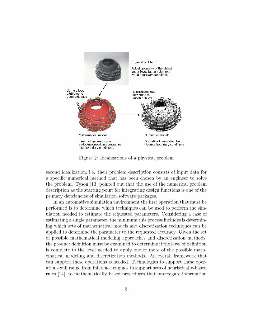
Figure 2: Idealizations of a physical problem
second idealization, i.e. their problem description consists of input data fora specific numerical method that has been chosen by an engineer to solvethe problem. Tyson [13] pointed out that the use of the numerical problemdescription as the starting point for integrating design functions is one of theprimary deficiencies of simulation software packages.
In an automative simulation environment the first operation that must beperformed is to determine which techniques can be used to perform the sim-ulation needed to estimate the requested parameters. Considering a case ofestimating a single parameter, the minimum this process includes is determin-ing which sets of mathematical models and discretization techniques can beapplied to determine the parameter to the requested accuracy. Given the setof possible mathematical modeling approaches and discretization methods,the product definition must be examined to determine if the level of definitionis complete to the level needed to apply one or more of the possible math-ematical modeling and discretization methods. An overall framework thatcan support these operations is needed. Technologies to support these oper-ations will range from inference engines to support sets of heuristically-basedrules [14], to mathematically based procedures that interrogate information
8

in the product definition to measure parameters needed for the decision onthe appropriate models. In the majority of simulation to be performed thereare no a-priori means to determine the level of accuracy to be obtained fromthe simulation. Over the past two decades researchers have been developingtechniques to take the results for a given simulation and, using knowledge ofthe approximations made in the process, estimating the errors for the simu-lation. The form of this information is such that it provides useful guidanceas the best means of improving the approximations made to gain the desiredlevel of accuracy. The application of knowledge in an adaptive feedback loop[15], [16] is the ideal means to obtain the accuracy desired. Adaptive feedbackprocedures for predicting simulation errors are only known for discretizationprocesses for some mathematical models, it is necessary to consider and sup-port all means that are, and may become, available to control all simulationerrors. These will range from heuristic rules, to specific levels of validationagainst experiments, to new mathematical modeling techniques.
2.3 Automatic Generation of Simulation Models
Given this set of decisions, the system must automatically generate the ini-tial discretization, associate the appropriate attributes with the discretiza-tion and perform the simulation. In the case when the discretization is of theexisting domain definition, the key capability needed is the appropriate au-tomatic domain discretization procedure. Although implementations of suchprocedures are available [17], most do not support the ability to create thediscretization directly from a non-manifold solid model. In addition, suchprocedures are available for only limited discretizations techniques. In thecases where the domain to be discretized for the analysis is different fromthat in the product definition, procedures are needed to account for these do-main differences. In many cases these procedures must perform dimensionalreductions of portions of the domain [18] and geometric simplification to re-move unneeded geometric details. In other cases, the information available inthe product definition must be used to drive geometric modeling operationsto define the forms of geometric representations needed by the automaticdiscretization procedures.
9
2.4 Geometry-Based Simulation Engine
The simulation engine needs to be implemented as an extendable frameworkfor the following reasons:
• The technologies needed for the full range of simulations that must beperformed is not known at this time. The flexibility of a well designedframework will allow it to incorporate future simulation needs rathereasily.
• There are a number of current CAE tools that can be applied as a majorcomponent of a simulation. Those tools can be incorporated into theframework and take over part of the simulation with the frameworkproviding the needed interface functionality.
• The range of applications to which simulation is applied will be con-stantly growing. Therefore, an effective simulation engine must providethe ability for domain experts to easily introduce new models withoutthe need to understand the details of the entire system.
Recently, Sahu et al. [19] presented such an extendable object-orientedframework for computational mechanics. It is designed to close the loopbetween CAD and analysis packages, facilitating the automatic solution ofcomplex evolutionary problems where both the mathematical and numer-ical models may evolve. Beall et al. [12] also present an object-orientedframework for computational mechanics. Their primary focus lies on devel-oping a simulation package that enables reliable numerical simulations in ageometry-based environment.
Conceptually the simulation framework is to be built on the view of ananalysis as a transformation between three levels of description [12], as itwas introduced in Figure 2. The goal of the analysis is to obtain reliableestimates of the response of the physical system. The mathematical problemdescription introduces some level of idealization, which needs to be controlledto yield the desired accuracy. The next step in the idealization introducesthe numerical problem, which is another set of idealizations that also need tobe controlled. Based on this view current CAE tools are simply the solutionengine to solve one single problem when it has reached the second idealizationstage in an overall adaptive process controlled by the framework.
10
The framework currently under development [12] makes use of modernsoftware development techniques [20],[21],[22] to make sure that it is extend-able. So far it has been used for Finite Element Analysis, as well as Partitionof Unity methods [3].
2.5 Product Data Management Tools
Product Data Management tools, which are also known as Engineering DataManagement systems (EDM) [23] were developed to manage all the datarelated to a product and the processes used to design, manufacture andsupport the product over the entire product lifecycle. Ideas, concept designs,engineering designs, test results and reports are examples of the data thatcan be put under control of a PDM system. A commercial grade database,like Informix [24], IBM’s DB2 [25], Oracle [26], or Sybase [27] forms thefundamental unit responsible for storing the raw data. The PDM systemsupports the presentation of the same data from different views according tothe needs and customs of the people working on that data. The improvedmanagement of the data helps to reduce the time and cost to introducenew products, and improves the quality of products. PDM systems aimto improve the overall product development cycle rather than improving anindividual task in one functional area, like a CAD system. A PDM systemcan be seen as the framework into which other systems, CAD, CAE etc. arebeing integrated.
2.6 Workflow Management System
With the data being controlled by a PDM system workflow management sys-tems (WfMS) [28], [29] can be used to coordinate and automate the executionof simulation processes. The flow of data between the different simulationtools is controlled through the use of software, according to a set of rulesthat have been designed using tools provided by the WfMS. Overall, pro-cessing time is being reduced, and the workflow can be monitored to identifybottlenecks. Workflow management systems are in high demand in largecorporations. However, many technologies (Database Management System,Workflow server, data bridging technologies) have to be integrated to suc-cessfully use such a system, which makes it rather challenging to reach theoverall goal.
11
For the purpose of automizing the design/simulation interaction the work-flow system needs to be responsible for the following tasks:
• Keying the need for a simulation initiated by
– a direct request of the designer to obtain estimates of requestedphysical parameters
– the need to update parameter estimates based on a design modi-fication
• Coordinating simulation processes in a distributed environment withmultiple organizations
Given the need to perform a simulation, the appropriate information mustbe abstracted from the product definition housed in the product data man-agement system. This includes the domain and the physical attributes neededfor the simulation. In cases where the domain to be spatially discretized isthe same as the product definition solid model, the workflow system needsto initiate the automatic mesh generation module and provide the neededinput. However, for more complicated cases the workflow system needs toinitiate the geometry and the idealization managers so that changes to themodel can be made before the automatic meshing procedures are activated,and idealizations are being linked back into the product definition.
3 Attribute System
Given our current automated simulation technologies, the key step to their in-tegration with an enterprise level system is to be able to maintain all problemdefinition information within the product data management system. Sinceour automated mesh generation tools already operate from the same solidmodel representations, the domain definition piece of the problem definitionis already taken care of. Although it may be possible to employ the attributespecification capabilities of those solid modelers to specify the analysis at-tributes, their inability to support the forms and functions needed by analysisattributes makes them unattractive. Therefore, it is desirable to build on thetype of analysis attribute specification capability described in this section.The problem with the available implementation is they used an independentset of data structures. To address this problem, the capabilities of those
12
structures have been implemented in a commercial database system com-monly used by product data management systems. This implementation isdescribed in section 4.
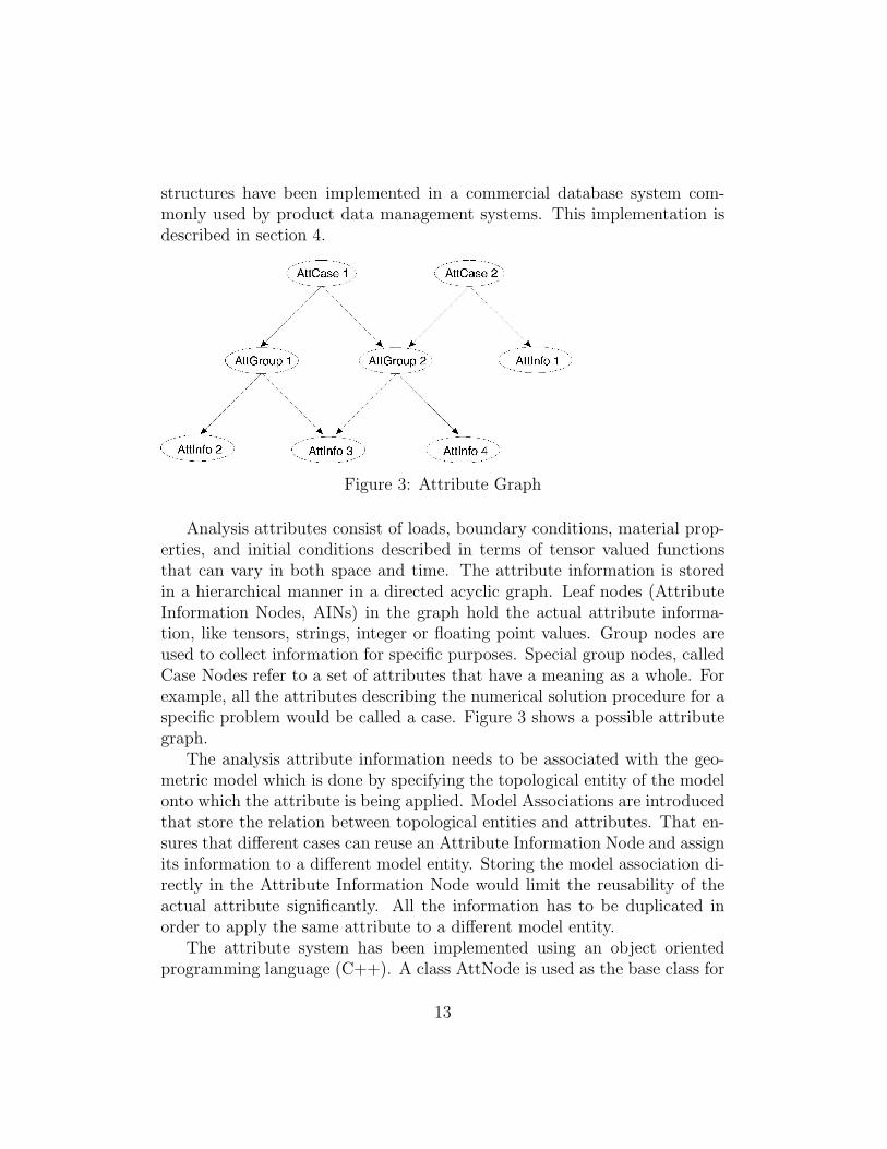
Figure 3: Attribute Graph
Analysis attributes consist of loads, boundary conditions, material prop-erties, and initial conditions described in terms of tensor valued functionsthat can vary in both space and time. The attribute information is storedin a hierarchical manner in a directed acyclic graph. Leaf nodes (AttributeInformation Nodes, AINs) in the graph hold the actual attribute informa-tion, like tensors, strings, integer or floating point values. Group nodes areused to collect information for specific purposes. Special group nodes, calledCase Nodes refer to a set of attributes that have a meaning as a whole. Forexample, all the attributes describing the numerical solution procedure for aspecific problem would be called a case. Figure 3 shows a possible attributegraph.
The analysis attribute information needs to be associated with the geo-metric model which is done by specifying the topological entity of the modelonto which the attribute is being applied. Model Associations are introducedthat store the relation between topological entities and attributes. That en-sures that different cases can reuse an Attribute Information Node and assignits information to a different model entity. Storing the model association di-rectly in the Attribute Information Node would limit the reusability of theactual attribute significantly. All the information has to be duplicated inorder to apply the same attribute to a different model entity.
The attribute system has been implemented using an object orientedprogramming language (C++). A class AttNode is used as the base class for
13
the Attribute Information Nodes storing the data common to all AttributeInformation Nodes. Specific classes for specialized information nodes, likeintegers, tensors etc. are derived from the base class and hold the informationspecific to those data types. The directed acyclic graph holding the attributeinformation is represented by appropriate pointers in the AttNode base class.A class ModelAssociation holds linked lists of topological entities from thegeometric model together with a linked list of AttNodes associated to them,and relates the lists to a case node.
4 Database Implementation
If any analysis attribute changes, previously computed results dependingon those attributes become invalid. The workflow system needs to monitorthose changes to be able to launch the appropriate simulations. Further,the designer might explicitly ask for certain results based on standard sim-ulation procedures stored in the workflow system. It becomes clear, thatthe attributes need to be stored in the product data management system tofacilitate the described processes.
As mentioned in the introduction PDM systems use a Relational DatabaseManagement System (RDBMS) [30], [31] as their back end to store productrelated data. A RDBMS is based on the relational data model that was firstintroduced in 1970 by Codd [32]. Based on that model all data is storedin tables or relations, including associations between the data. Accordingto [31], a relation is a named, two-dimensional table of data consisting ofa set of columns and an arbitrary number of rows. Relations have certainproperties that distinguish them from nonrelational tables:
• Entries in columns are atomic.
• Entries in columns are from the same domain.
• Each row is unique.
• The sequence of columns and rows is insignificant.
These properties allow application of set theory operations performedon the data stored in a RDBMS. The well understood set theory gives therelational data model a solid foundation which was one major reason for thesuccess of RDBMSs.
14
The accepted standard interface to a relational database is the StructuredQuery Language (SQL) [33],[34]. SQL is a data sublanguage, with the onlypurpose to provide an interface to a relational database. Therefore, all SQLstatements are instructions to the database. SQL provides statements for avariety of tasks, including: Querying data, inserting, updating and deletingrows in a table, creating, replacing, altering, and dropping objects as well ascontrolling access to the database and its objects.
The database chosen for the implementation was Oracle 8i [35], [36].However, there are no Oracle specific details in the implementation. Anystandard SQL database that provides a C or C++ API is sufficient. Forthe actual interface to the database the Oracle and Odbc Template Library(OTL) (Version 3.1) [37] was used. OTL is a C++ template library providingthin wrappers around the database APIs based on SQL. OTL covers the func-tionality of a whole database API based on the C++ stream concept. Dueto the template concept the OTL code gets expanded into direct databaseAPI function calls, which provides good performance, reliability and threadsafety in multi-processor environments as well as traditional batch programs.
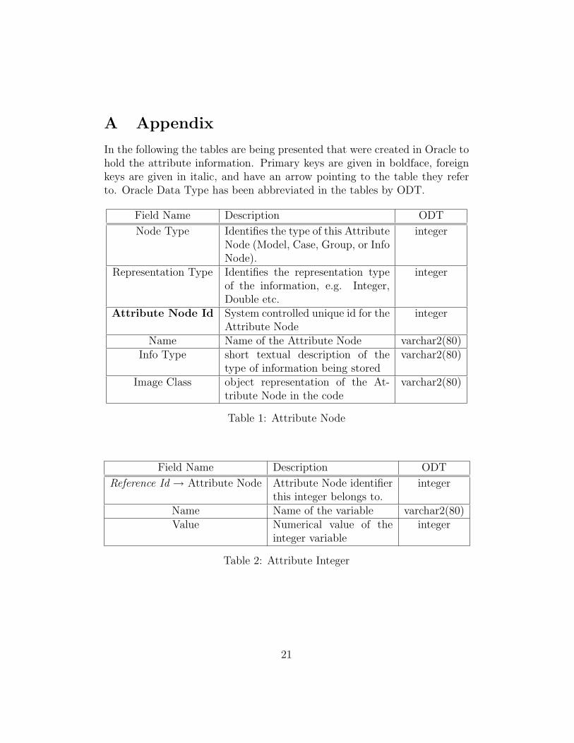
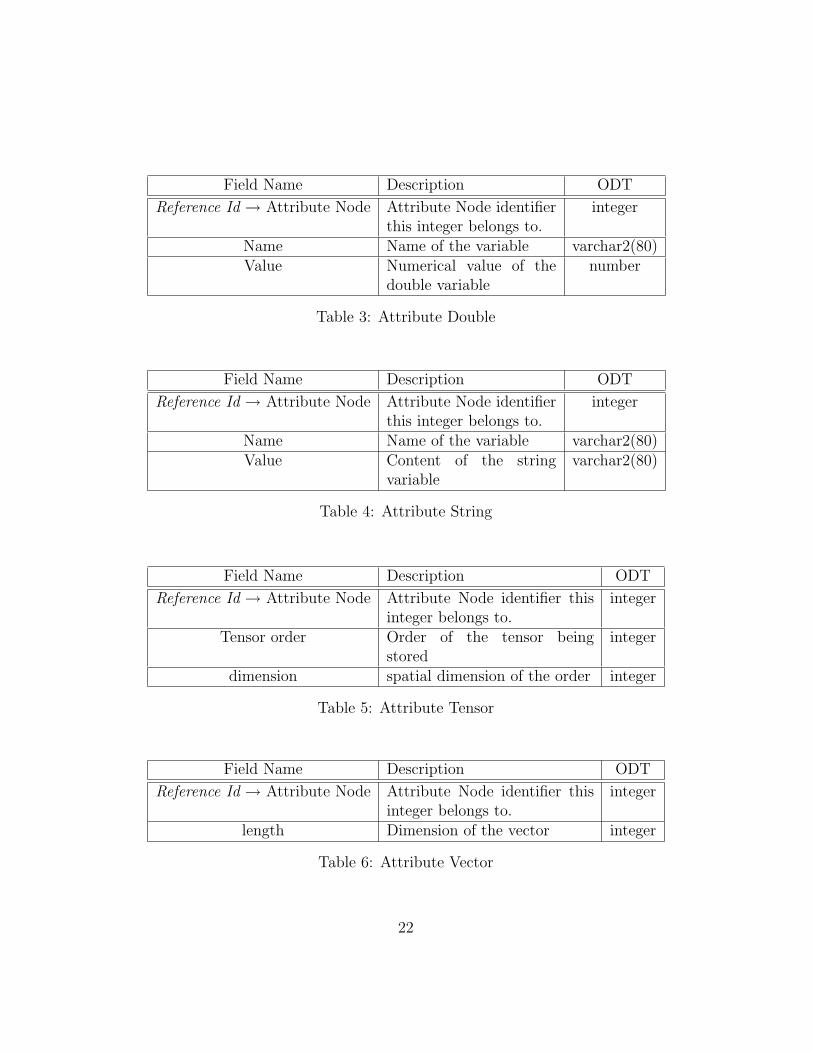
To store the attribute data in a RDBMS the object structure of the im-plementation, as well as the data structure of the acyclic directed graphholding the attribute information had to be mapped into tables. The deriva-tion of the C++ class structures has been implemented by constructing atable for the base class containing a primary key, as well as tables for thederived classes which contain a foreign key pointing to the base class table.Specifically, the table for the base class is given in Table 1. It contains theinformation that is stored in the C++ base class AttNode. The id of thatnode has been chosen as the primary key. The tables for the derived classes(Tables 2 to 6) contain a foreign key referencing the corresponding attributenode entry in the Attribute Node Table 1. Since the attribute system canhold vectors of any order the Attribute Vector is being stored in two tables,where one table stores the dimension of the vector (Table 6) and the secondtable (Table 7) holds the information about the entries in the vector. Again,the unique Attribute Node Id is being used to relate the table entries to eachother.
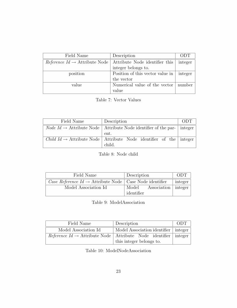
The directed acyclic graph represents a parent – child relationship in anextended way. Extended since a child can have an unlimited number ofparents. The relationship has been mapped into a table by simply storingthe Ids of the two related Attribute Nodes in a table (see Table 8).
15

The model associations are stored using several tables. The first table,called ModelAssociation (Table 9), stores the relation of the model associa-tion to the case nodes. Table ModelNodeAssociation (Table 10) relates themodel associations with the Attribute Node Ids. The missing link to thetopological entities of the geometric model is stored in table ModelEntityAs-sociation (Table 11). When the geometric model is known those three tablesallow retrieval of the association of attributes to the entities of a geomet-ric model for a given case. As given for the C++ structure the storage ofattribute and topological entity is separated in the table structure to allowthe reuse of attributes without duplicating the information. The geometricmodel is stored as an entry in the Attribute Node table, and is associatedwith a case through a reference in the ModelCaseAssociation table (Table12).
5 Closing remarks
This paper has described a simulation environment to support engineering de-sign embedded in an enterprise wide information system. The different com-ponents of that environment are under development at the Scientific Com-putation Research Center (SCOREC). The level of functionality achieved asof today varies greatly with each component. There exist already a commer-cialized version of one of the generation tools developed at SCOREC (MEGA[38]), and significant contributions have been made to the geometry-basedsimulation engine, the information structures and managers ([12], [39], [11]),and the adaptive control tools. The interaction with the product data man-agement tool was described in this paper, and an initial version of a workflowmanager has been implemented. However, further research is required to im-prove their applicability to industrial sized problems, and to allow for a fullyautomized simulation environment in an industrial setting.
6 Acknowledgements
We would like to thank Christophe Dupre for many discussions and helpfulcomments regarding the database implementation of the attribute system.
16
References
[1] Arabshahi, S.; Barton, D.C.; Shaw, N.K. (1993) Steps towards CAD-FEA Integration, Engineering with Computers, 9, 17 – 26.
[2] Beall, M.W.; Shephard, M.S. (1997) A general topology-based mesh datastructure, International Journal for Numerical Methods in Engineering,40(9), 1573 – 1596.
[3] Klaas, O.; Shephard, M.S. (2000) Automatic Generation of Octree basedThree Dimensional Discretizations for Partition of Unity Methods, Com-putational Mechanics, 25(2/3), 296 – 304.
[4] ISO STEP, “Industrial Automation Systems - Product Data Represen-tations and Exchange - Part 1: Overview and Fundamental Principals”,ISO Report CD/10303-1.
[5] ISO STEP, “Industrial Automation Systems - Product Data Represen-tations and Exchange - Part 42: Integrated Resources: Geometric andTopological Representations”, ISO Report CD/10303-42.
[6] Shephard, M.S.; Georges, M.K. (1992) Reliability of Automatic 3-DMesh Generation, Computational Methods in Applied Mechanics andEngineering, 101, 443 – 462
[7] Shephard, M.S.; Georges, M.K. (1991) Automatic Three-dimensionalMesh Generation by the Finite Octree Technique, International Journalfor Numerical Methods in Engineering, 32(4), 709 – 749.
[8] Weiler, K. (1988) The Radial Edge Structure: A Topological Represen-tation for Non-Manifold Geometric Modeling, Geometric Modeling forCAD Applications (IFIP WG5.2 Working Conference Rensselaerville,N.Y., May 12-14), Eds.: Wozny, M.J,; McLaughlin, H.; Encarnacao, J.,3 – 36.
[9] Shephard, M.S. (1988) The specification of physical attribute informa-tion for engineering analysis, Engineering with Computers, 4, 145 – 155.
[10] Shephard M.S.; Finnigan, P.M. (1989) Toward Automatic Model Gen-eration, State-of-the-Art Surveys on Computational Mechanics. A.K.Noor and J.T. Oden, eds., ASME, 335 - 366.
17
[11] O’Bara R.M.; Beall, M.W.; Shephard, M.S. (1997) Specifying AnalysisInformation within a Geometry-Based Framework, Procedures of theFourth US National Congress on Computational Mechanics, USACM,137.
[12] Beall, M.W.; Shephard, M.S. (1999) An Object-Oriented Framework forReliable Numerical Simulations, Engineering with Computers, 15(1), 61– 72.
[13] Tyson, T.R. (1991) Effective Automation for Structural Design, Journalof Computing in Civil Engineering, 5(2), 132 – 140.
[14] Holzhauer, D.; Grosse, I. (1999) Finite element analysis using com-ponent decomposition and knowledge-based control, Engineering withComputers, 15(4), 315 – 325.
[15] Oden, J.T.; Demkowicz, L. (1992) Computer Methods in Applied Me-chanics and Engineering, Special Issue on the reliability of finite elementcomputations, North Holland, 101.
[16] Shephard, M.S.; Baehmann, P.L.; Georges, M.K.; Korngold, E.V. (1990)Framework for the Reliable Generation and Control of Analysis Ideal-izations, Computer Methods in Applied Mechanics and Engineering, 82,257 – 280.
[17] Shephard M.S. (1996) Update to: approaches to the automatic genera-tion and control of finite element meshes, Applied Mechanics Reviews,49(10/2), 5 – 14.
[18] Rezayat, M. (1996) Midsurface abstraction from 3D solid models: gen-eral theory and applications, Computer-Aided Design, 28(11), 905 –915.
[19] Sahu, R.; Panthaki, M.J.; Gerstle, W.H. (1999) An Object-Oriented Framework for Multidisciplinary, Multi-Physics, Computa-tional Mechancs, Engineering with Computers, 15(1), 105 – 125.
[20] Stroustrup, B. (1997) The C++ Programming Language, 3rd edition,Addison-Wesley.
18

[21] Matthew, H.A. (1998) Generic Programming and the STL, Addison-Wesley.
[22] Gamma, E.; Helm, R.; Johnson, R.; Vlissides, J. (1994) Design Patterns:Elements of Reusable Object-Oriented Software, Addison-Wesley.
[23] McIntosh, K. G. (1995) Engineering Data Management: a guide to suc-cessful implementation. McGraw-Hill.
[24] Informix Software Inc., 4100 Bohannon Drive, Menlo Park, CA 94025,USA. Web address: http:/www.informix.com
[25] IBM North America, 1133 Westchester Avenue, White Plains NY 10604,USA. Web address: http:/www.ibm.com
[26] Oracle Corporation, 500 Oracle Parkway, Redwood Shores, Ca 94065,USA. Web address: http://www.oracle.com
[27] Sybase Inc., 6475 Christie Ave., Emeryville, CA 94608, USA. Web ad-dress: http://www.sybase.com
[28] Workflow Management Coalition (1995). The Workflow Ref-erence Model. Document Number TC00-1003. Accessible via:http://www.aiim.org/wfmc
[29] Mohan, C.; Alonso, G.; Gunthor, R.; Kamath, M. (1995) Exotica: AResearch Perspective on Workflow Management Systems. Data Engi-neering, 18(1), 19 – 26.
[30] Date, J.C (1999) An Introduction to Database System, Addison-Wesley.
[31] McFadden, F.R.; Hoffer, J.A. (1999) Modern Database Management,5th edition, Addison-Wesley.
[32] Codd, E.F. (1970) A Relational Model of Data for Large RelationalDatabases, Communications of the ACM 13, 6.
[33] American National Standards Institute: ANSI X3.135-1992, ”DatabaseLanguage SQL”
[34] International Standards Organization: ISO/IEC 9075:1992, ”DatabaseLanguage SQL”
19
[35] Loney, K.; Theriault, M. (1999) Oracle 8i DBA Handbook. Osborne McGraw-Hill.
[36] Oracle8i, SQL Reference (1999). Release 8.1.5. Part No. A67779-01.
[37] Kuchin, S. (2000) Oracle and Odbc Template Library Programmer’sGuide. Accessible via: http://home.sprynet.com/ skuchin/
[38] Shephard, M.S. (2000) Meshing environment for geometry-based analy-sis, International Journal for Numerical Methods in Engineering, 47(1–3), 169 – 190.
[39] O’Bara, R.M.; Beall, M.W.; Shephard, M.S. (in preparation) AttributeManagement System for Engineering Analysis.
20
A Appendix
In the following the tables are being presented that were created in Oracle tohold the attribute information. Primary keys are given in boldface, foreignkeys are given in italic, and have an arrow pointing to the table they referto. Oracle Data Type has been abbreviated in the tables by ODT.
Field Name Description ODT
Node Type Identifies the type of this AttributeNode (Model, Case, Group, or InfoNode).
integer
Representation Type Identifies the representation typeof the information, e.g. Integer,Double etc.
integer
Attribute Node Id System controlled unique id for theAttribute Node
integer
Name Name of the Attribute Node varchar2(80)Info Type short textual description of the
type of information being storedvarchar2(80)
Image Class object representation of the At-tribute Node in the code
varchar2(80)
Table 1: Attribute Node
Field Name Description ODT
Reference Id → Attribute Node Attribute Node identifierthis integer belongs to.
integer
Name Name of the variable varchar2(80)Value Numerical value of the
integer variableinteger
Table 2: Attribute Integer
21
Field Name Description ODT
Reference Id → Attribute Node Attribute Node identifierthis integer belongs to.
integer
Name Name of the variable varchar2(80)Value Numerical value of the
double variablenumber
Table 3: Attribute Double
Field Name Description ODT
Reference Id → Attribute Node Attribute Node identifierthis integer belongs to.
integer
Name Name of the variable varchar2(80)Value Content of the string
variablevarchar2(80)
Table 4: Attribute String
Field Name Description ODT
Reference Id → Attribute Node Attribute Node identifier thisinteger belongs to.
integer
Tensor order Order of the tensor beingstored
integer
dimension spatial dimension of the order integer
Table 5: Attribute Tensor
Field Name Description ODT
Reference Id → Attribute Node Attribute Node identifier thisinteger belongs to.
integer
length Dimension of the vector integer
Table 6: Attribute Vector
22
Field Name Description ODT
Reference Id → Attribute Node Attribute Node identifier thisinteger belongs to.
integer
position Position of this vector value inthe vector
integer
value Numerical value of the vectorvalue
number
Table 7: Vector Values
Field Name Description ODT
Node Id → Attribute Node Attribute Node identifier of the par-ent.
integer
Child Id → Attribute Node Attribute Node identifier of thechild.
integer
Table 8: Node child
Field Name Description ODT
Case Reference Id → Attribute Node Case Node identifier integerModel Association Id Model Association
identifierinteger
Table 9: ModelAssociation
Field Name Description ODT
Model Association Id Model Association identifier integerReference Id → Attribute Node Attribute Node identifier
this integer belongs to.integer
Table 10: ModelNodeAssociation
23
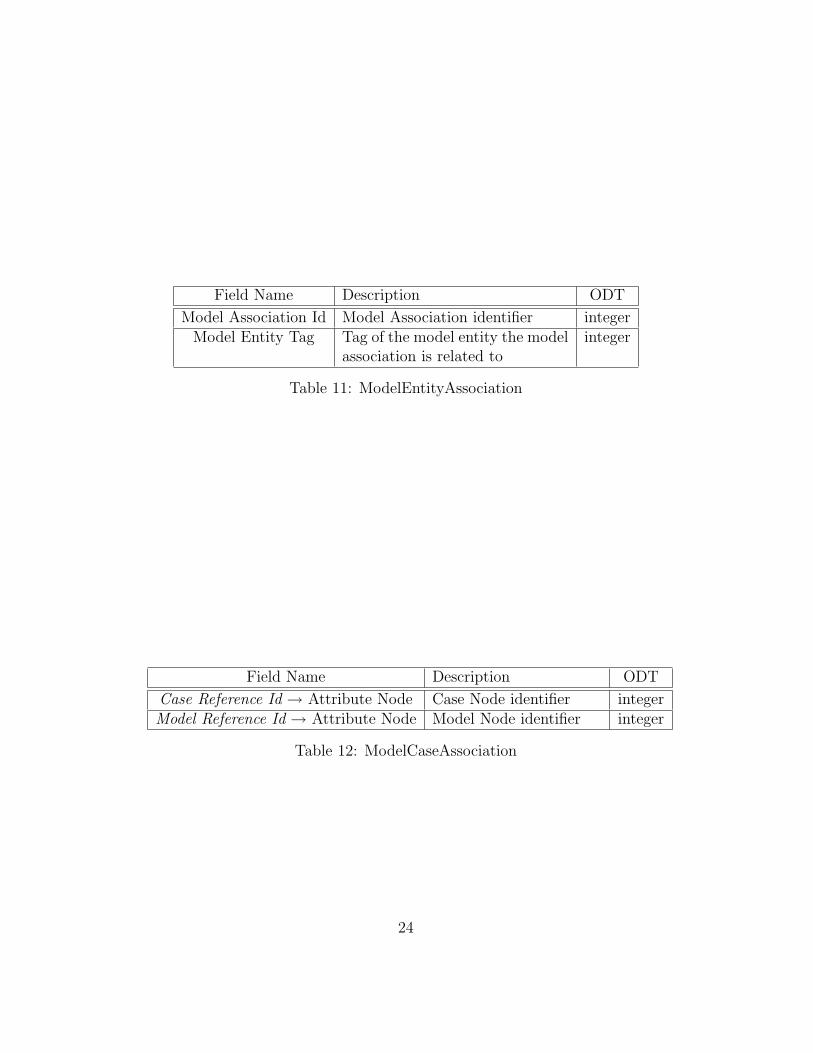
Field Name Description ODT
Model Association Id Model Association identifier integerModel Entity Tag Tag of the model entity the model
association is related tointeger
Table 11: ModelEntityAssociation
Field Name Description ODT
Case Reference Id → Attribute Node Case Node identifier integerModel Reference Id → Attribute Node Model Node identifier integer
Table 12: ModelCaseAssociation
24