embodied computation: exploring roboforming for the mass-customization of architectural components
DESCRIPTION
This my thesis book as of Fall 2013. More to come by May 2014.TRANSCRIPT

Embodied Computation:Advisors: Jeremy Ficca, Josh Bard, David Kosbie Alex J Fischer.com/thesis
Exploring Roboforming for the Mass-Customization of Architectural Components

2

3
Introduction

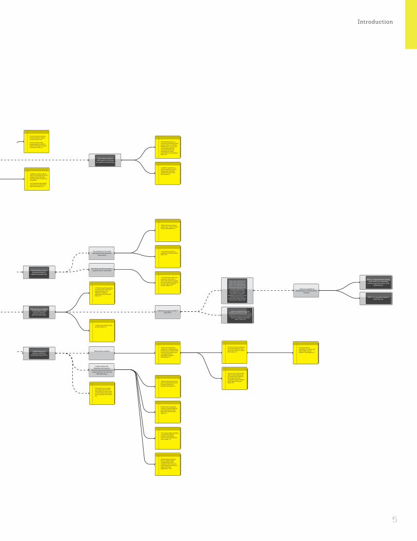
Argument Map - Part 1/2 - Roboforming
I should research how roboforming can be utilized in
mass customization of architectural components.
Roboforming is the embodiment of more for less and can be
utilzied to realize the goal of
mass-customization in architecture.
Roboforming along with 3D-plasma cutting
offers new possibilities in mass-customization.
My research should focus on the design possibilities of
roboforming and creating a fluid process chain for future
use of this method in architecture.
Research into new methods of making can help architects regain control in the AEC
industry.
Architecture should adopt ideas of mass customization.
There is a need for efficient manufacturing techniques for
complex surfaces.
Mass customization of architectural components is
inherently different than in other industries.
I am a designer, maker and programmer.
Roboforming process has not yet been applied to a large,
complex project.
There does not exist a CAM system to calculate
tool paths for roboforming.
Roboforming is still not accurate enough for
reliable mantufacturing.
Roboforming is a dieless incremental forming process using two
synchronized robots.
Roboforming is an efficient method for
producing unique forms.
Duplex Incremental Forming with Locally supporting tool (DPIF-l): “the supporting tool
moves at the other side of the sheet directly opposite to the
forming tool, generating a forming gap between both
tools. Especially for complex geometries, through the
exchange of both tools’ forming and supporting functions,
convex and concave structures can be formed.” (Meier, 38)
Duplex Incremental Forming with Peripheral supporting tool (DPIF-P): “a
supporting tool is synchronized with the forming tool moving on the boundary of
the part to substitute the backing plates.” (Meier, 38)
AISF is a new process for forming sheet metal by incrementally
forming a geometry with a small spherical tool.
AISF is not accurate enough for legitimate use.
3D-plasma cutting of the sheet metal before and after forming
has not yet been tested.
Mass-customization is a recently emerged method in
the 21st Century
Mass-customization can be econmically viable
Software Can enable mass-customization
Cars and airplanes are built from modules assembled
off-site
Ships are built using grand blocks
Modulation and parallelism are core concepts of computer
science
Modulation allows for complex problems to be broken down into a series of smaller, less
complex problems
Modulation decreases time to assemble
Modulation decreases labor costs
Mass-customization increases quality
Mass-customization is desired
The is a shortage of skilled labor
The role of architects has been diminished
Brunelleschi
Vitruvius
Architecture costs more and delivers less
Sister industries have found ways to reduce costs and
increase quality
Architects used to be master builders
Architects deal primarily with appearance
Modulation assemblies that limited choice are not desired
Architecture should be made modular
I am not principaly a researcher and should not attempt to do
the job of an engineer or material scientist.
The thickness of the sheet decreases in the process of
roboforming.
Roboforming refers to DPIF-P and DPIF-L
...which is a variation of Asymetrical Incremental Sheet
Forming.
Simulating roboforming takes a long time and is not precise.
Computers, automobiles, and current architecture are
personalized. A person decides from a set of predetermined
options.
Architectural components are customied based on location
and parameters including program, forces, and
environment.
Scripts Increase Effiency
Incorporating material computation into architectureal designs increases quality and
decreases cost
Modulation failed to catch on in architecture.
Mass-customization is desired and can increase
quality.
CAD/CAM is not being exploited to its fullest
potential.
Methods of mass-customization are expensive.
It is now possible to mass produce custom forms.
Architects are creating more and more complex
forms
This is much like the current state of architecture. Parts provided my manufacturers are premade and can be chosen by the architect, but the architect does not get to
design these parts. So this personalization rather than
customization.
Cars and computers have families of parts and provide them
as options.
Manufacturing methods have caught up
Modulation of architecture has been tried before
Consumers desire choice
Mass production is less for less
Automobiles
Tesla
Computer science
Planes
Ships
It is possible to create complex forms never before possible
Dell computers allow customers to choose the speed they need by selecting from a few part options.
Research to increase roboforming’s accuracy is
already underway.
Research is needed to increase the accuracy of
roboforming.
There are gaps in the existing research that I
can fill.
I shoudn’t focus on improving the accuracy
of this process.
“In the realm of architecture Trautz and Herkrath (2009) examined AISF for manufacturing different elements of a double-layered. facet-like folding structure.” (Bruninghaus, 1)
“the whole CAx process has not been applied to a large complex geometry yet”
I will be creating a large complex geometry with this method, which can fill the gap in this paper. (Meier, 41)
“In Roboforming the supporting tool driven by the slave robot supports the part on its backside according to individual surface structures.” (Meier, 37)
Roborming is scalable
Experts agree that Roboforming is ideal for
manufacturing small batches of unique parts for low cost and
high effieciency
Roboforming is a new rapid prototyping method to form sheet metals by means of two universal forming tools driven by two industrial robots” (Meier, 37)
“a dieless incremental forming process” (Meier, 37)
Personalization = Mass-Customization(Woudhuysen, 50)
Callicott proposed that “complexity and variety in architecture can be explored beyond the prior bounds of standardisation, yet within an economic framework increasingly favourable to the unique.”(Callicott, 66)
“Since Roboforming is an innovative incremental forming process, there is no existing CAM-solution to quickly and accurately generate two synchronized tool paths according to the above mentioned forming strategies.” (Meier, 38)
“for DPIF-P and DPIF-L no direct analogous process in milling exists. thus CAM systems cannot be used.” (Bruninghaus, 3)
“The FEM model needs to be improved in future work, in which reducing the calculation time and raising the simulation accuracy are the research focuses.” (Meier, 41)
“reduced sheet thickness caused by the fixed boundary” (Meier, 39)
“Material thinning in formed areas” occurs “since the sheet is fixed.” (Bruninghaus, 2)
Incremental sheet forming (ISF) is a highly flexible manufacturing process suitable for low volume and rapid prototype production of sheet metal parts. (Katajarinne, 1175)
This process makes it possible to produce the different elements of the folding structure with minimized tool costs. (Trautz, 11)
“The algorithm is much easier to handle than the set of drawings – especially when it comes to changes”(Scheurer, ”Materialising Complexity.”, 91)An argument for algorithms that can take in inputs, such as the component, and parametrically figure out the tooling and manufacturing process for that particular component. This requires abstraction of the problem to one which a computer program can solve.
“The danger is that computer power triumphs over design and takes away the need to simplify, rationalise and understand the material.”(Thornton, 103)This is why I will begin with empirical physical tests on sheet metal to understand the material and how it deforms.
“the best designers know how things work, how they are made, how materials behave and their qualities.”(Thornton, 101)
Timberlake argues, ”‘If today’s new materials enable integration, lighter assemblies and new technologies, then the world of design and construction will be enhanced by embracing them, rather than ignoring their possibilities.”(Woudhuysen, 51)Sheet metal is not a new material, certainly, but new technologies for production are integral to lighter assemblies.
“Materiality and materialisation can become the starting points of an exploratory, open-ended design process, and thus serve, quite literally, as the raw materials for design research and architectural inquiry.”(Menges, ”Material Computation”, 16)
“Cars ships, and planes must even move through space, while buildings, relatively static artifacts, are rooted in place. Ships are larger than most buildings and generally dynamic.”(Kieran and Timberlake, 11)
“Cars ships, and planes must even move through space, while buildings, relatively static artifacts, are rooted in place. Ships are larger than most buildings and generally dynamic.”(Kieran and Timberlake, 11)
Roboforming “is especially suitable for rapid prototyping and manufacture of small batch sizes with low costs.” (Meier, 37)
Therefore free-formed unique parts or small batches can be produced cheaply and speedily. (Bruninghaus, 1)
Modular ‘smart elements’ that may have a shorter service life can be swapped out easily.(Kieran and Timberlake, 77)
“complex problem is made into a series of smaller, less complex ones”(Kieran and Timberlake, 97)
“when responsibility for the car is fragmented into modules, there are more entities assuming primary responsibility for this quality”(Kieran and Timberlake, 89)
“The architect has allowed the means and methods of building to move outside the sphere of architecture. The splintering of architecture into segregated specialties has been disastrous.”(Kieran and Timberlake, 31)
“Ironically, by narrowing its realm of significant interest to appearance only, architecture sacrificed control of its one remaining stronghold: appearance.”(Kieran and Timberlake, 29)
“The more one attempts to undertake at the point of final assembly, the more difficult it is to control quality. Fewer joints in the final installation give rise to more precise tolerances”(Kieran and Timberlake, 87)argument for preassembly
Aggregating “many parts into fewer modules before the point of final assembly” achieves “higher quality, better features, less time to fabricate, and lower cost: more art and craft, not less.”(Kieran and Timberlake, 79-81)
“the use of an industrial robot system enables large-sized structures to be formed with lower equipment costs compared to a CNC-machine with a large working area.” (Meier, 37)
The maximum sheet thickness for forming “depends on the forces the machine can apply.” (Bruninghaus, 2)
“Mass customization is a hybrid” between mass production and customization. ”It proposes new processes to build using automated production, but with the ability to differentiate each artifact from those that re fabricated before and after.”(Kieran and Timberlake, xii-xiii)
Mass Customisation: the production of individual components at almost the price of mass production through the use of digitally controlled (CNC) fabrication tools.(Scheurer, ”Materialising Complexity.”, 91)
Forming forces are “dependent on material, wall angle, infeed, and tool diameter.” (Bruninghaus, 2)
“Since the forming forces needed are not dependent on the dimension of the part AISF can be used to produce even very large parts with inexpensive machines.” (Bruninghaus, 1)
Feedback loops between computational design, advanced simulation and robotic fabrication will enable a complex performative structure from a simple system.(Menges, ”Material Computation”, 17)
“Architecture, as a material practice, attains social, cultural and ecological relevance through the articulation of material arrangements and structures. Thus, the way we conceptualise these material interventions- and particularly the technology that enables their construction – presents a fundamental aspect in how we (re)think architecture.”(Menges, “Integral Formation and Materialisation”, 198)
“Architectural production over the past decade has been marked by a strong affection for the image. The seductive aesthetics of digital architectural modelling and visualisation have often dominated over attention towards materiality and building construction. There appears to be something remarkable in the interaction of the material and the formal qualities that produces a distinguished quality of design. It is perhaps the elevation of materiality to a level of prominence in design and design research that can explain this intellectual resonance and its implications for architecture as a material practice.”(Weinand, 107)More arguments for incorporating research of material behavior into the architectural design process.
“Additional conditions like the relief of the clamped sheet, the cutting and even the warm forming process could also be considered.”
I can experiment with plasma cutting the sheet before and after forming. (Meier, 41)
“Katajarinne mentioned the production of metal facade elements as a use case for AISF” (Bruninghaus, 1)
“it can be difficult to carry out physical research, as opposed to a desk study, because it takes time and money, even though the cost might be a small part of the project cost and should anyway be set against the reduction in risk and savings that arise from the research. Inevitably, without the reassurance of research, the design must be more cautious.”(Thornton, 101)
Practical and material orientated academic research has become increasingly important for architectural practice, due to several factors.(Weinand, 104)
It contributes to contemporary concepts in architecture and improves their implementation. It is the limitations in time and capacities that more often than not confound the realisation of such ambitions. Academic research can fill this gap and provide architectural practices with the necessary resources. Research has a duty to address how to achieve sustainable building.
Personalization is when a person decides from a set of predetermined
options.
Architectural components are customized based on location and parameters.
Modulation is the key to increase quality and
scope while decreasing cost and time in sister
industries
Architecture should look towards sister industries
for answers
Modulation increases quality
Mass Customisation: the production of individual components at almost the price of mass production through the use of digitally controlled (CNC) fabrication tools.(Scheurer, ”Materialising Complexity.”, 91)
“There was also a project on responsive skin where AISF was used to manufacture a mold, which is then used for injection molding UPM Profi – a recycled paper composite – at UCLA Architecture & Urban Design.” (Bruninghaus, 1)
The seminar will focus on developing a design process which uses analytical data, such as solar gain analysis, to drive the scripted panelisation of a building form. The designs of the paneling systems are done within the constrains of a digital fabrication process called incremental sheet forming forming, in which an industrial robot presses a sheet of metal against a computer guided piston ‘field’ in order to create a mould, which can be used for injection moulding UPM Profi - a recycled paper composite. (Cadiz)
“Throughout the development of the physical and digital tools for this process, feedback has constantly been taken and given between design and fabrication. These parameters are being used in the design to influence the metal skin’s global curvatures, local subdivision, and surface articulations to increase forming accuracy. The metal formed panels have been analuzed using 3D scalling technologies to understand where the structural ribs are needed for stabilization. The formed ribs are used as dynamic currugations across the aggregation which makes a structured skin that identifies panel location.” (Newsumme)
Past architectural designs utilizing single-point
incremental sheet forming to produce facade systems
Research is needed in this area as
mass-customization is the future of architecture
Mass customization is more for less
“Why are we constantly forced to make design decisions on the basis of costs that result in less choice, less customization, more standardization, and less quality?”(Kieran and Timberlake, 135)
Corbu’s “mass-produced housing modeled on American automotive production, numerous factory-produced houses of the WWII era and the industrialized building program of Operation Breakthrough in the Nixon era” (Kieran and Timberlake, 105)
Embodied Computation
4
Introduction
I should research how roboforming can be utilized in
mass customization of architectural components.
Roboforming is the embodiment of more for less and can be
utilzied to realize the goal of
mass-customization in architecture.
Roboforming along with 3D-plasma cutting
offers new possibilities in mass-customization.
My research should focus on the design possibilities of
roboforming and creating a fluid process chain for future
use of this method in architecture.
Research into new methods of making can help architects regain control in the AEC
industry.
Architecture should adopt ideas of mass customization.
There is a need for efficient manufacturing techniques for
complex surfaces.
Mass customization of architectural components is
inherently different than in other industries.
I am a designer, maker and programmer.
Roboforming process has not yet been applied to a large,
complex project.
There does not exist a CAM system to calculate
tool paths for roboforming.
Roboforming is still not accurate enough for
reliable mantufacturing.
Roboforming is a dieless incremental forming process using two
synchronized robots.
Roboforming is an efficient method for
producing unique forms.
Duplex Incremental Forming with Locally supporting tool (DPIF-l): “the supporting tool
moves at the other side of the sheet directly opposite to the
forming tool, generating a forming gap between both
tools. Especially for complex geometries, through the
exchange of both tools’ forming and supporting functions,
convex and concave structures can be formed.” (Meier, 38)
Duplex Incremental Forming with Peripheral supporting tool (DPIF-P): “a
supporting tool is synchronized with the forming tool moving on the boundary of
the part to substitute the backing plates.” (Meier, 38)
AISF is a new process for forming sheet metal by incrementally
forming a geometry with a small spherical tool.
AISF is not accurate enough for legitimate use.
3D-plasma cutting of the sheet metal before and after forming
has not yet been tested.
Mass-customization is a recently emerged method in
the 21st Century
Mass-customization can be econmically viable
Software Can enable mass-customization
Cars and airplanes are built from modules assembled
off-site
Ships are built using grand blocks
Modulation and parallelism are core concepts of computer
science
Modulation allows for complex problems to be broken down into a series of smaller, less
complex problems
Modulation decreases time to assemble
Modulation decreases labor costs
Mass-customization increases quality
Mass-customization is desired
The is a shortage of skilled labor
The role of architects has been diminished
Brunelleschi
Vitruvius
Architecture costs more and delivers less
Sister industries have found ways to reduce costs and
increase quality
Architects used to be master builders
Architects deal primarily with appearance
Modulation assemblies that limited choice are not desired
Architecture should be made modular
I am not principaly a researcher and should not attempt to do
the job of an engineer or material scientist.
The thickness of the sheet decreases in the process of
roboforming.
Roboforming refers to DPIF-P and DPIF-L
...which is a variation of Asymetrical Incremental Sheet
Forming.
Simulating roboforming takes a long time and is not precise.
Computers, automobiles, and current architecture are
personalized. A person decides from a set of predetermined
options.
Architectural components are customied based on location
and parameters including program, forces, and
environment.
Scripts Increase Effiency
Incorporating material computation into architectureal designs increases quality and
decreases cost
Modulation failed to catch on in architecture.
Mass-customization is desired and can increase
quality.
CAD/CAM is not being exploited to its fullest
potential.
Methods of mass-customization are expensive.
It is now possible to mass produce custom forms.
Architects are creating more and more complex
forms
This is much like the current state of architecture. Parts provided my manufacturers are premade and can be chosen by the architect, but the architect does not get to
design these parts. So this personalization rather than
customization.
Cars and computers have families of parts and provide them
as options.
Manufacturing methods have caught up
Modulation of architecture has been tried before
Consumers desire choice
Mass production is less for less
Automobiles
Tesla
Computer science
Planes
Ships
It is possible to create complex forms never before possible
Dell computers allow customers to choose the speed they need by selecting from a few part options.
Research to increase roboforming’s accuracy is
already underway.
Research is needed to increase the accuracy of
roboforming.
There are gaps in the existing research that I
can fill.
I shoudn’t focus on improving the accuracy
of this process.
“In the realm of architecture Trautz and Herkrath (2009) examined AISF for manufacturing different elements of a double-layered. facet-like folding structure.” (Bruninghaus, 1)
“the whole CAx process has not been applied to a large complex geometry yet”
I will be creating a large complex geometry with this method, which can fill the gap in this paper. (Meier, 41)
“In Roboforming the supporting tool driven by the slave robot supports the part on its backside according to individual surface structures.” (Meier, 37)
Roborming is scalable
Experts agree that Roboforming is ideal for
manufacturing small batches of unique parts for low cost and
high effieciency
Roboforming is a new rapid prototyping method to form sheet metals by means of two universal forming tools driven by two industrial robots” (Meier, 37)
“a dieless incremental forming process” (Meier, 37)
Personalization = Mass-Customization(Woudhuysen, 50)
Callicott proposed that “complexity and variety in architecture can be explored beyond the prior bounds of standardisation, yet within an economic framework increasingly favourable to the unique.”(Callicott, 66)
“Since Roboforming is an innovative incremental forming process, there is no existing CAM-solution to quickly and accurately generate two synchronized tool paths according to the above mentioned forming strategies.” (Meier, 38)
“for DPIF-P and DPIF-L no direct analogous process in milling exists. thus CAM systems cannot be used.” (Bruninghaus, 3)
“The FEM model needs to be improved in future work, in which reducing the calculation time and raising the simulation accuracy are the research focuses.” (Meier, 41)
“reduced sheet thickness caused by the fixed boundary” (Meier, 39)
“Material thinning in formed areas” occurs “since the sheet is fixed.” (Bruninghaus, 2)
Incremental sheet forming (ISF) is a highly flexible manufacturing process suitable for low volume and rapid prototype production of sheet metal parts. (Katajarinne, 1175)
This process makes it possible to produce the different elements of the folding structure with minimized tool costs. (Trautz, 11)
“The algorithm is much easier to handle than the set of drawings – especially when it comes to changes”(Scheurer, ”Materialising Complexity.”, 91)An argument for algorithms that can take in inputs, such as the component, and parametrically figure out the tooling and manufacturing process for that particular component. This requires abstraction of the problem to one which a computer program can solve.
“The danger is that computer power triumphs over design and takes away the need to simplify, rationalise and understand the material.”(Thornton, 103)This is why I will begin with empirical physical tests on sheet metal to understand the material and how it deforms.
“the best designers know how things work, how they are made, how materials behave and their qualities.”(Thornton, 101)
Timberlake argues, ”‘If today’s new materials enable integration, lighter assemblies and new technologies, then the world of design and construction will be enhanced by embracing them, rather than ignoring their possibilities.”(Woudhuysen, 51)Sheet metal is not a new material, certainly, but new technologies for production are integral to lighter assemblies.
“Materiality and materialisation can become the starting points of an exploratory, open-ended design process, and thus serve, quite literally, as the raw materials for design research and architectural inquiry.”(Menges, ”Material Computation”, 16)
“Cars ships, and planes must even move through space, while buildings, relatively static artifacts, are rooted in place. Ships are larger than most buildings and generally dynamic.”(Kieran and Timberlake, 11)
“Cars ships, and planes must even move through space, while buildings, relatively static artifacts, are rooted in place. Ships are larger than most buildings and generally dynamic.”(Kieran and Timberlake, 11)
Roboforming “is especially suitable for rapid prototyping and manufacture of small batch sizes with low costs.” (Meier, 37)
Therefore free-formed unique parts or small batches can be produced cheaply and speedily. (Bruninghaus, 1)
Modular ‘smart elements’ that may have a shorter service life can be swapped out easily.(Kieran and Timberlake, 77)
“complex problem is made into a series of smaller, less complex ones”(Kieran and Timberlake, 97)
“when responsibility for the car is fragmented into modules, there are more entities assuming primary responsibility for this quality”(Kieran and Timberlake, 89)
“The architect has allowed the means and methods of building to move outside the sphere of architecture. The splintering of architecture into segregated specialties has been disastrous.”(Kieran and Timberlake, 31)
“Ironically, by narrowing its realm of significant interest to appearance only, architecture sacrificed control of its one remaining stronghold: appearance.”(Kieran and Timberlake, 29)
“The more one attempts to undertake at the point of final assembly, the more difficult it is to control quality. Fewer joints in the final installation give rise to more precise tolerances”(Kieran and Timberlake, 87)argument for preassembly
Aggregating “many parts into fewer modules before the point of final assembly” achieves “higher quality, better features, less time to fabricate, and lower cost: more art and craft, not less.”(Kieran and Timberlake, 79-81)
“the use of an industrial robot system enables large-sized structures to be formed with lower equipment costs compared to a CNC-machine with a large working area.” (Meier, 37)
The maximum sheet thickness for forming “depends on the forces the machine can apply.” (Bruninghaus, 2)
“Mass customization is a hybrid” between mass production and customization. ”It proposes new processes to build using automated production, but with the ability to differentiate each artifact from those that re fabricated before and after.”(Kieran and Timberlake, xii-xiii)
Mass Customisation: the production of individual components at almost the price of mass production through the use of digitally controlled (CNC) fabrication tools.(Scheurer, ”Materialising Complexity.”, 91)
Forming forces are “dependent on material, wall angle, infeed, and tool diameter.” (Bruninghaus, 2)
“Since the forming forces needed are not dependent on the dimension of the part AISF can be used to produce even very large parts with inexpensive machines.” (Bruninghaus, 1)
Feedback loops between computational design, advanced simulation and robotic fabrication will enable a complex performative structure from a simple system.(Menges, ”Material Computation”, 17)
“Architecture, as a material practice, attains social, cultural and ecological relevance through the articulation of material arrangements and structures. Thus, the way we conceptualise these material interventions- and particularly the technology that enables their construction – presents a fundamental aspect in how we (re)think architecture.”(Menges, “Integral Formation and Materialisation”, 198)
“Architectural production over the past decade has been marked by a strong affection for the image. The seductive aesthetics of digital architectural modelling and visualisation have often dominated over attention towards materiality and building construction. There appears to be something remarkable in the interaction of the material and the formal qualities that produces a distinguished quality of design. It is perhaps the elevation of materiality to a level of prominence in design and design research that can explain this intellectual resonance and its implications for architecture as a material practice.”(Weinand, 107)More arguments for incorporating research of material behavior into the architectural design process.
“Additional conditions like the relief of the clamped sheet, the cutting and even the warm forming process could also be considered.”
I can experiment with plasma cutting the sheet before and after forming. (Meier, 41)
“Katajarinne mentioned the production of metal facade elements as a use case for AISF” (Bruninghaus, 1)
“it can be difficult to carry out physical research, as opposed to a desk study, because it takes time and money, even though the cost might be a small part of the project cost and should anyway be set against the reduction in risk and savings that arise from the research. Inevitably, without the reassurance of research, the design must be more cautious.”(Thornton, 101)
Practical and material orientated academic research has become increasingly important for architectural practice, due to several factors.(Weinand, 104)
It contributes to contemporary concepts in architecture and improves their implementation. It is the limitations in time and capacities that more often than not confound the realisation of such ambitions. Academic research can fill this gap and provide architectural practices with the necessary resources. Research has a duty to address how to achieve sustainable building.
Practical and material orientated academic research has become increasingly important for architectural practice, due to several factors.(Weinand, 104)
It contributes to contemporary concepts in architecture and improves their implementation. It is the limitations in time and capacities that more often than not confound the realisation of such ambitions. Academic research can fill this gap and provide architectural practices with the necessary resources. Research has a duty to address how to achieve sustainable building.
Personalization is when a person decides from a set of predetermined
options.
Architectural components are customized based on location and parameters.
Modulation is the key to increase quality and
scope while decreasing cost and time in sister
industries
Architecture should look towards sister industries
for answers
Modulation increases quality
Mass Customisation: the production of individual components at almost the price of mass production through the use of digitally controlled (CNC) fabrication tools.(Scheurer, ”Materialising Complexity.”, 91)
“There was also a project on responsive skin where AISF was used to manufacture a mold, which is then used for injection molding UPM Profi – a recycled paper composite – at UCLA Architecture & Urban Design.” (Bruninghaus, 1)
The seminar will focus on developing a design process which uses analytical data, such as solar gain analysis, to drive the scripted panelisation of a building form. The designs of the paneling systems are done within the constrains of a digital fabrication process called incremental sheet forming forming, in which an industrial robot presses a sheet of metal against a computer guided piston ‘field’ in order to create a mould, which can be used for injection moulding UPM Profi - a recycled paper composite. (Cadiz)
“Throughout the development of the physical and digital tools for this process, feedback has constantly been taken and given between design and fabrication. These parameters are being used in the design to influence the metal skin’s global curvatures, local subdivision, and surface articulations to increase forming accuracy. The metal formed panels have been analuzed using 3D scalling technologies to understand where the structural ribs are needed for stabilization. The formed ribs are used as dynamic currugations across the aggregation which makes a structured skin that identifies panel location.” (Newsumme)
Past architectural designs utilizing single-point
incremental sheet forming to produce facade systems
Research is needed in this area as
mass-customization is the future of architecture
Mass customization is more for less
“Why are we constantly forced to make design decisions on the basis of costs that result in less choice, less customization, more standardization, and less quality?”(Kieran and Timberlake, 135)
Corbu’s “mass-produced housing modeled on American automotive production, numerous factory-produced houses of the WWII era and the industrialized building program of Operation Breakthrough in the Nixon era” (Kieran and Timberlake, 105)
5

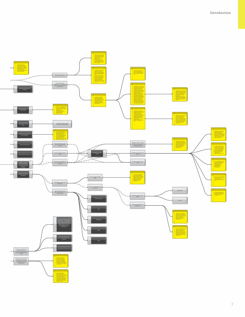
Argument Map - Part 2/2 - Modulation and Mass-Customization
I should research how roboforming can be utilized in
mass customization of architectural components.
Roboforming is the embodiment of more for less and can be
utilzied to realize the goal of
mass-customization in architecture.
Roboforming along with 3D-plasma cutting
offers new possibilities in mass-customization.
My research should focus on the design possibilities of
roboforming and creating a fluid process chain for future
use of this method in architecture.
Research into new methods of making can help architects regain control in the AEC
industry.
Architecture should adopt ideas of mass customization.
There is a need for efficient manufacturing techniques for
complex surfaces.
Mass customization of architectural components is
inherently different than in other industries.
I am a designer, maker and programmer.
Roboforming process has not yet been applied to a large,
complex project.
There does not exist a CAM system to calculate
tool paths for roboforming.
Roboforming is still not accurate enough for
reliable mantufacturing.
Roboforming is a dieless incremental forming process using two
synchronized robots.
Roboforming is an efficient method for
producing unique forms.
Duplex Incremental Forming with Locally supporting tool (DPIF-l): “the supporting tool
moves at the other side of the sheet directly opposite to the
forming tool, generating a forming gap between both
tools. Especially for complex geometries, through the
exchange of both tools’ forming and supporting functions,
convex and concave structures can be formed.” (Meier, 38)
Duplex Incremental Forming with Peripheral supporting tool (DPIF-P): “a
supporting tool is synchronized with the forming tool moving on the boundary of
the part to substitute the backing plates.” (Meier, 38)
AISF is a new process for forming sheet metal by incrementally
forming a geometry with a small spherical tool.
AISF is not accurate enough for legitimate use.
3D-plasma cutting of the sheet metal before and after forming
has not yet been tested.
Mass-customization is a recently emerged method in
the 21st Century
Mass-customization can be econmically viable
Software Can enable mass-customization
Cars and airplanes are built from modules assembled
off-site
Ships are built using grand blocks
Modulation and parallelism are core concepts of computer
science
Modulation allows for complex problems to be broken down into a series of smaller, less
complex problems
Modulation decreases time to assemble
Modulation decreases labor costs
Mass-customization increases quality
Mass-customization is desired
The is a shortage of skilled labor
The role of architects has been diminished
Brunelleschi
Vitruvius
Architecture costs more and delivers less
Sister industries have found ways to reduce costs and
increase quality
Architects used to be master builders
Architects deal primarily with appearance
Modulation assemblies that limited choice are not desired
Architecture should be made modular
I am not principaly a researcher and should not attempt to do
the job of an engineer or material scientist.
The thickness of the sheet decreases in the process of
roboforming.
Roboforming refers to DPIF-P and DPIF-L
...which is a variation of Asymetrical Incremental Sheet
Forming.
Simulating roboforming takes a long time and is not precise.
Computers, automobiles, and current architecture are
personalized. A person decides from a set of predetermined
options.
Architectural components are customied based on location
and parameters including program, forces, and
environment.
Scripts Increase Effiency
Incorporating material computation into architectureal designs increases quality and
decreases cost
Modulation failed to catch on in architecture.
Mass-customization is desired and can increase
quality.
CAD/CAM is not being exploited to its fullest
potential.
Methods of mass-customization are expensive.
It is now possible to mass produce custom forms.
Architects are creating more and more complex
forms
This is much like the current state of architecture. Parts provided my manufacturers are premade and can be chosen by the architect, but the architect does not get to
design these parts. So this personalization rather than
customization.
Cars and computers have families of parts and provide them
as options.
Manufacturing methods have caught up
Modulation of architecture has been tried before
Consumers desire choice
Mass production is less for less
Automobiles
Tesla
Computer science
Planes
Ships
It is possible to create complex forms never before possible
Dell computers allow customers to choose the speed they need by selecting from a few part options.
Research to increase roboforming’s accuracy is
already underway.
Research is needed to increase the accuracy of
roboforming.
There are gaps in the existing research that I
can fill.
I shoudn’t focus on improving the accuracy
of this process.
“In the realm of architecture Trautz and Herkrath (2009) examined AISF for manufacturing different elements of a double-layered. facet-like folding structure.” (Bruninghaus, 1)
“the whole CAx process has not been applied to a large complex geometry yet”
I will be creating a large complex geometry with this method, which can fill the gap in this paper. (Meier, 41)
“In Roboforming the supporting tool driven by the slave robot supports the part on its backside according to individual surface structures.” (Meier, 37)
Roborming is scalable
Experts agree that Roboforming is ideal for
manufacturing small batches of unique parts for low cost and
high effieciency
Roboforming is a new rapid prototyping method to form sheet metals by means of two universal forming tools driven by two industrial robots” (Meier, 37)
“a dieless incremental forming process” (Meier, 37)
Personalization = Mass-Customization(Woudhuysen, 50)
Callicott proposed that “complexity and variety in architecture can be explored beyond the prior bounds of standardisation, yet within an economic framework increasingly favourable to the unique.”(Callicott, 66)
“Since Roboforming is an innovative incremental forming process, there is no existing CAM-solution to quickly and accurately generate two synchronized tool paths according to the above mentioned forming strategies.” (Meier, 38)
“for DPIF-P and DPIF-L no direct analogous process in milling exists. thus CAM systems cannot be used.” (Bruninghaus, 3)
“The FEM model needs to be improved in future work, in which reducing the calculation time and raising the simulation accuracy are the research focuses.” (Meier, 41)
“reduced sheet thickness caused by the fixed boundary” (Meier, 39)
“Material thinning in formed areas” occurs “since the sheet is fixed.” (Bruninghaus, 2)
Incremental sheet forming (ISF) is a highly flexible manufacturing process suitable for low volume and rapid prototype production of sheet metal parts. (Katajarinne, 1175)
This process makes it possible to produce the different elements of the folding structure with minimized tool costs. (Trautz, 11)
“The algorithm is much easier to handle than the set of drawings – especially when it comes to changes”(Scheurer, ”Materialising Complexity.”, 91)An argument for algorithms that can take in inputs, such as the component, and parametrically figure out the tooling and manufacturing process for that particular component. This requires abstraction of the problem to one which a computer program can solve.
“The danger is that computer power triumphs over design and takes away the need to simplify, rationalise and understand the material.”(Thornton, 103)This is why I will begin with empirical physical tests on sheet metal to understand the material and how it deforms.
“the best designers know how things work, how they are made, how materials behave and their qualities.”(Thornton, 101)
Timberlake argues, ”‘If today’s new materials enable integration, lighter assemblies and new technologies, then the world of design and construction will be enhanced by embracing them, rather than ignoring their possibilities.”(Woudhuysen, 51)Sheet metal is not a new material, certainly, but new technologies for production are integral to lighter assemblies.
“Materiality and materialisation can become the starting points of an exploratory, open-ended design process, and thus serve, quite literally, as the raw materials for design research and architectural inquiry.”(Menges, ”Material Computation”, 16)
“Cars ships, and planes must even move through space, while buildings, relatively static artifacts, are rooted in place. Ships are larger than most buildings and generally dynamic.”(Kieran and Timberlake, 11)
“Cars ships, and planes must even move through space, while buildings, relatively static artifacts, are rooted in place. Ships are larger than most buildings and generally dynamic.”(Kieran and Timberlake, 11)
Roboforming “is especially suitable for rapid prototyping and manufacture of small batch sizes with low costs.” (Meier, 37)
Therefore free-formed unique parts or small batches can be produced cheaply and speedily. (Bruninghaus, 1)
Modular ‘smart elements’ that may have a shorter service life can be swapped out easily.(Kieran and Timberlake, 77)
“complex problem is made into a series of smaller, less complex ones”(Kieran and Timberlake, 97)
“when responsibility for the car is fragmented into modules, there are more entities assuming primary responsibility for this quality”(Kieran and Timberlake, 89)
“The architect has allowed the means and methods of building to move outside the sphere of architecture. The splintering of architecture into segregated specialties has been disastrous.”(Kieran and Timberlake, 31)
“Ironically, by narrowing its realm of significant interest to appearance only, architecture sacrificed control of its one remaining stronghold: appearance.”(Kieran and Timberlake, 29)
“The more one attempts to undertake at the point of final assembly, the more difficult it is to control quality. Fewer joints in the final installation give rise to more precise tolerances”(Kieran and Timberlake, 87)argument for preassembly
Aggregating “many parts into fewer modules before the point of final assembly” achieves “higher quality, better features, less time to fabricate, and lower cost: more art and craft, not less.”(Kieran and Timberlake, 79-81)
“the use of an industrial robot system enables large-sized structures to be formed with lower equipment costs compared to a CNC-machine with a large working area.” (Meier, 37)
The maximum sheet thickness for forming “depends on the forces the machine can apply.” (Bruninghaus, 2)
“Mass customization is a hybrid” between mass production and customization. ”It proposes new processes to build using automated production, but with the ability to differentiate each artifact from those that re fabricated before and after.”(Kieran and Timberlake, xii-xiii)
Mass Customisation: the production of individual components at almost the price of mass production through the use of digitally controlled (CNC) fabrication tools.(Scheurer, ”Materialising Complexity.”, 91)
Forming forces are “dependent on material, wall angle, infeed, and tool diameter.” (Bruninghaus, 2)
“Since the forming forces needed are not dependent on the dimension of the part AISF can be used to produce even very large parts with inexpensive machines.” (Bruninghaus, 1)
Feedback loops between computational design, advanced simulation and robotic fabrication will enable a complex performative structure from a simple system.(Menges, ”Material Computation”, 17)
“Architecture, as a material practice, attains social, cultural and ecological relevance through the articulation of material arrangements and structures. Thus, the way we conceptualise these material interventions- and particularly the technology that enables their construction – presents a fundamental aspect in how we (re)think architecture.”(Menges, “Integral Formation and Materialisation”, 198)
“Architectural production over the past decade has been marked by a strong affection for the image. The seductive aesthetics of digital architectural modelling and visualisation have often dominated over attention towards materiality and building construction. There appears to be something remarkable in the interaction of the material and the formal qualities that produces a distinguished quality of design. It is perhaps the elevation of materiality to a level of prominence in design and design research that can explain this intellectual resonance and its implications for architecture as a material practice.”(Weinand, 107)More arguments for incorporating research of material behavior into the architectural design process.
“Additional conditions like the relief of the clamped sheet, the cutting and even the warm forming process could also be considered.”
I can experiment with plasma cutting the sheet before and after forming. (Meier, 41)
“Katajarinne mentioned the production of metal facade elements as a use case for AISF” (Bruninghaus, 1)
“it can be difficult to carry out physical research, as opposed to a desk study, because it takes time and money, even though the cost might be a small part of the project cost and should anyway be set against the reduction in risk and savings that arise from the research. Inevitably, without the reassurance of research, the design must be more cautious.”(Thornton, 101)
Practical and material orientated academic research has become increasingly important for architectural practice, due to several factors.(Weinand, 104)
It contributes to contemporary concepts in architecture and improves their implementation. It is the limitations in time and capacities that more often than not confound the realisation of such ambitions. Academic research can fill this gap and provide architectural practices with the necessary resources. Research has a duty to address how to achieve sustainable building.
Practical and material orientated academic research has become increasingly important for architectural practice, due to several factors.(Weinand, 104)
It contributes to contemporary concepts in architecture and improves their implementation. It is the limitations in time and capacities that more often than not confound the realisation of such ambitions. Academic research can fill this gap and provide architectural practices with the necessary resources. Research has a duty to address how to achieve sustainable building.
Personalization is when a person decides from a set of predetermined
options.
Architectural components are customized based on location and parameters.
Modulation is the key to increase quality and
scope while decreasing cost and time in sister
industries
Architecture should look towards sister industries
for answers
Modulation increases quality
Mass Customisation: the production of individual components at almost the price of mass production through the use of digitally controlled (CNC) fabrication tools.(Scheurer, ”Materialising Complexity.”, 91)
“There was also a project on responsive skin where AISF was used to manufacture a mold, which is then used for injection molding UPM Profi – a recycled paper composite – at UCLA Architecture & Urban Design.” (Bruninghaus, 1)
The seminar will focus on developing a design process which uses analytical data, such as solar gain analysis, to drive the scripted panelisation of a building form. The designs of the paneling systems are done within the constrains of a digital fabrication process called incremental sheet forming forming, in which an industrial robot presses a sheet of metal against a computer guided piston ‘field’ in order to create a mould, which can be used for injection moulding UPM Profi - a recycled paper composite. (Cadiz)
“Throughout the development of the physical and digital tools for this process, feedback has constantly been taken and given between design and fabrication. These parameters are being used in the design to influence the metal skin’s global curvatures, local subdivision, and surface articulations to increase forming accuracy. The metal formed panels have been analuzed using 3D scalling technologies to understand where the structural ribs are needed for stabilization. The formed ribs are used as dynamic currugations across the aggregation which makes a structured skin that identifies panel location.” (Newsumme)
Past architectural designs utilizing single-point
incremental sheet forming to produce facade systems
Research is needed in this area as
mass-customization is the future of architecture
Mass customization is more for less
“Why are we constantly forced to make design decisions on the basis of costs that result in less choice, less customization, more standardization, and less quality?”(Kieran and Timberlake, 135)
Corbu’s “mass-produced housing modeled on American automotive production, numerous factory-produced houses of the WWII era and the industrialized building program of Operation Breakthrough in the Nixon era” (Kieran and Timberlake, 105)
Embodied Computation
6
IntroductionI should research how roboforming can be utilized in
mass customization of architectural components.
Roboforming is the embodiment of more for less and can be
utilzied to realize the goal of
mass-customization in architecture.
Roboforming along with 3D-plasma cutting
offers new possibilities in mass-customization.
My research should focus on the design possibilities of
roboforming and creating a fluid process chain for future
use of this method in architecture.
Research into new methods of making can help architects regain control in the AEC
industry.
Architecture should adopt ideas of mass customization.
There is a need for efficient manufacturing techniques for
complex surfaces.
Mass customization of architectural components is
inherently different than in other industries.
I am a designer, maker and programmer.
Roboforming process has not yet been applied to a large,
complex project.
There does not exist a CAM system to calculate
tool paths for roboforming.
Roboforming is still not accurate enough for
reliable mantufacturing.
Roboforming is a dieless incremental forming process using two
synchronized robots.
Roboforming is an efficient method for
producing unique forms.
Duplex Incremental Forming with Locally supporting tool (DPIF-l): “the supporting tool
moves at the other side of the sheet directly opposite to the
forming tool, generating a forming gap between both
tools. Especially for complex geometries, through the
exchange of both tools’ forming and supporting functions,
convex and concave structures can be formed.” (Meier, 38)
Duplex Incremental Forming with Peripheral supporting tool (DPIF-P): “a
supporting tool is synchronized with the forming tool moving on the boundary of
the part to substitute the backing plates.” (Meier, 38)
AISF is a new process for forming sheet metal by incrementally
forming a geometry with a small spherical tool.
AISF is not accurate enough for legitimate use.
3D-plasma cutting of the sheet metal before and after forming
has not yet been tested.
Mass-customization is a recently emerged method in
the 21st Century
Mass-customization can be econmically viable
Software Can enable mass-customization
Cars and airplanes are built from modules assembled
off-site
Ships are built using grand blocks
Modulation and parallelism are core concepts of computer
science
Modulation allows for complex problems to be broken down into a series of smaller, less
complex problems
Modulation decreases time to assemble
Modulation decreases labor costs
Mass-customization increases quality
Mass-customization is desired
The is a shortage of skilled labor
The role of architects has been diminished
Brunelleschi
Vitruvius
Architecture costs more and delivers less
Sister industries have found ways to reduce costs and
increase quality
Architects used to be master builders
Architects deal primarily with appearance
Modulation assemblies that limited choice are not desired
Architecture should be made modular
I am not principaly a researcher and should not attempt to do
the job of an engineer or material scientist.
The thickness of the sheet decreases in the process of
roboforming.
Roboforming refers to DPIF-P and DPIF-L
...which is a variation of Asymetrical Incremental Sheet
Forming.
Simulating roboforming takes a long time and is not precise.
Computers, automobiles, and current architecture are
personalized. A person decides from a set of predetermined
options.
Architectural components are customied based on location
and parameters including program, forces, and
environment.
Scripts Increase Effiency
Incorporating material computation into architectureal designs increases quality and
decreases cost
Modulation failed to catch on in architecture.
Mass-customization is desired and can increase
quality.
CAD/CAM is not being exploited to its fullest
potential.
Methods of mass-customization are expensive.
It is now possible to mass produce custom forms.
Architects are creating more and more complex
forms
This is much like the current state of architecture. Parts provided my manufacturers are premade and can be chosen by the architect, but the architect does not get to
design these parts. So this personalization rather than
customization.
Cars and computers have families of parts and provide them
as options.
Manufacturing methods have caught up
Modulation of architecture has been tried before
Consumers desire choice
Mass production is less for less
Automobiles
Tesla
Computer science
Planes
Ships
It is possible to create complex forms never before possible
Dell computers allow customers to choose the speed they need by selecting from a few part options.
Research to increase roboforming’s accuracy is
already underway.
Research is needed to increase the accuracy of
roboforming.
There are gaps in the existing research that I
can fill.
I shoudn’t focus on improving the accuracy
of this process.
“In the realm of architecture Trautz and Herkrath (2009) examined AISF for manufacturing different elements of a double-layered. facet-like folding structure.” (Bruninghaus, 1)
“the whole CAx process has not been applied to a large complex geometry yet”
I will be creating a large complex geometry with this method, which can fill the gap in this paper. (Meier, 41)
“In Roboforming the supporting tool driven by the slave robot supports the part on its backside according to individual surface structures.” (Meier, 37)
Roborming is scalable
Experts agree that Roboforming is ideal for
manufacturing small batches of unique parts for low cost and
high effieciency
Roboforming is a new rapid prototyping method to form sheet metals by means of two universal forming tools driven by two industrial robots” (Meier, 37)
“a dieless incremental forming process” (Meier, 37)
Personalization = Mass-Customization(Woudhuysen, 50)
Callicott proposed that “complexity and variety in architecture can be explored beyond the prior bounds of standardisation, yet within an economic framework increasingly favourable to the unique.”(Callicott, 66)
“Since Roboforming is an innovative incremental forming process, there is no existing CAM-solution to quickly and accurately generate two synchronized tool paths according to the above mentioned forming strategies.” (Meier, 38)
“for DPIF-P and DPIF-L no direct analogous process in milling exists. thus CAM systems cannot be used.” (Bruninghaus, 3)
“The FEM model needs to be improved in future work, in which reducing the calculation time and raising the simulation accuracy are the research focuses.” (Meier, 41)
“reduced sheet thickness caused by the fixed boundary” (Meier, 39)
“Material thinning in formed areas” occurs “since the sheet is fixed.” (Bruninghaus, 2)
Incremental sheet forming (ISF) is a highly flexible manufacturing process suitable for low volume and rapid prototype production of sheet metal parts. (Katajarinne, 1175)
This process makes it possible to produce the different elements of the folding structure with minimized tool costs. (Trautz, 11)
“The algorithm is much easier to handle than the set of drawings – especially when it comes to changes”(Scheurer, ”Materialising Complexity.”, 91)An argument for algorithms that can take in inputs, such as the component, and parametrically figure out the tooling and manufacturing process for that particular component. This requires abstraction of the problem to one which a computer program can solve.
“The danger is that computer power triumphs over design and takes away the need to simplify, rationalise and understand the material.”(Thornton, 103)This is why I will begin with empirical physical tests on sheet metal to understand the material and how it deforms.
“the best designers know how things work, how they are made, how materials behave and their qualities.”(Thornton, 101)
Timberlake argues, ”‘If today’s new materials enable integration, lighter assemblies and new technologies, then the world of design and construction will be enhanced by embracing them, rather than ignoring their possibilities.”(Woudhuysen, 51)Sheet metal is not a new material, certainly, but new technologies for production are integral to lighter assemblies.
“Materiality and materialisation can become the starting points of an exploratory, open-ended design process, and thus serve, quite literally, as the raw materials for design research and architectural inquiry.”(Menges, ”Material Computation”, 16)
“Cars ships, and planes must even move through space, while buildings, relatively static artifacts, are rooted in place. Ships are larger than most buildings and generally dynamic.”(Kieran and Timberlake, 11)
“Cars ships, and planes must even move through space, while buildings, relatively static artifacts, are rooted in place. Ships are larger than most buildings and generally dynamic.”(Kieran and Timberlake, 11)
Roboforming “is especially suitable for rapid prototyping and manufacture of small batch sizes with low costs.” (Meier, 37)
Therefore free-formed unique parts or small batches can be produced cheaply and speedily. (Bruninghaus, 1)
Modular ‘smart elements’ that may have a shorter service life can be swapped out easily.(Kieran and Timberlake, 77)
“complex problem is made into a series of smaller, less complex ones”(Kieran and Timberlake, 97)
“when responsibility for the car is fragmented into modules, there are more entities assuming primary responsibility for this quality”(Kieran and Timberlake, 89)
“The architect has allowed the means and methods of building to move outside the sphere of architecture. The splintering of architecture into segregated specialties has been disastrous.”(Kieran and Timberlake, 31)
“Ironically, by narrowing its realm of significant interest to appearance only, architecture sacrificed control of its one remaining stronghold: appearance.”(Kieran and Timberlake, 29)
“The more one attempts to undertake at the point of final assembly, the more difficult it is to control quality. Fewer joints in the final installation give rise to more precise tolerances”(Kieran and Timberlake, 87)argument for preassembly
Aggregating “many parts into fewer modules before the point of final assembly” achieves “higher quality, better features, less time to fabricate, and lower cost: more art and craft, not less.”(Kieran and Timberlake, 79-81)
“the use of an industrial robot system enables large-sized structures to be formed with lower equipment costs compared to a CNC-machine with a large working area.” (Meier, 37)
The maximum sheet thickness for forming “depends on the forces the machine can apply.” (Bruninghaus, 2)
“Mass customization is a hybrid” between mass production and customization. ”It proposes new processes to build using automated production, but with the ability to differentiate each artifact from those that re fabricated before and after.”(Kieran and Timberlake, xii-xiii)
Mass Customisation: the production of individual components at almost the price of mass production through the use of digitally controlled (CNC) fabrication tools.(Scheurer, ”Materialising Complexity.”, 91)
Forming forces are “dependent on material, wall angle, infeed, and tool diameter.” (Bruninghaus, 2)
“Since the forming forces needed are not dependent on the dimension of the part AISF can be used to produce even very large parts with inexpensive machines.” (Bruninghaus, 1)
Feedback loops between computational design, advanced simulation and robotic fabrication will enable a complex performative structure from a simple system.(Menges, ”Material Computation”, 17)
“Architecture, as a material practice, attains social, cultural and ecological relevance through the articulation of material arrangements and structures. Thus, the way we conceptualise these material interventions- and particularly the technology that enables their construction – presents a fundamental aspect in how we (re)think architecture.”(Menges, “Integral Formation and Materialisation”, 198)
“Architectural production over the past decade has been marked by a strong affection for the image. The seductive aesthetics of digital architectural modelling and visualisation have often dominated over attention towards materiality and building construction. There appears to be something remarkable in the interaction of the material and the formal qualities that produces a distinguished quality of design. It is perhaps the elevation of materiality to a level of prominence in design and design research that can explain this intellectual resonance and its implications for architecture as a material practice.”(Weinand, 107)More arguments for incorporating research of material behavior into the architectural design process.
“Additional conditions like the relief of the clamped sheet, the cutting and even the warm forming process could also be considered.”
I can experiment with plasma cutting the sheet before and after forming. (Meier, 41)
“Katajarinne mentioned the production of metal facade elements as a use case for AISF” (Bruninghaus, 1)
“it can be difficult to carry out physical research, as opposed to a desk study, because it takes time and money, even though the cost might be a small part of the project cost and should anyway be set against the reduction in risk and savings that arise from the research. Inevitably, without the reassurance of research, the design must be more cautious.”(Thornton, 101)
Practical and material orientated academic research has become increasingly important for architectural practice, due to several factors.(Weinand, 104)
It contributes to contemporary concepts in architecture and improves their implementation. It is the limitations in time and capacities that more often than not confound the realisation of such ambitions. Academic research can fill this gap and provide architectural practices with the necessary resources. Research has a duty to address how to achieve sustainable building.
Practical and material orientated academic research has become increasingly important for architectural practice, due to several factors.(Weinand, 104)
It contributes to contemporary concepts in architecture and improves their implementation. It is the limitations in time and capacities that more often than not confound the realisation of such ambitions. Academic research can fill this gap and provide architectural practices with the necessary resources. Research has a duty to address how to achieve sustainable building.
Personalization is when a person decides from a set of predetermined
options.
Architectural components are customized based on location and parameters.
Modulation is the key to increase quality and
scope while decreasing cost and time in sister
industries
Architecture should look towards sister industries
for answers
Modulation increases quality
Mass Customisation: the production of individual components at almost the price of mass production through the use of digitally controlled (CNC) fabrication tools.(Scheurer, ”Materialising Complexity.”, 91)
“There was also a project on responsive skin where AISF was used to manufacture a mold, which is then used for injection molding UPM Profi – a recycled paper composite – at UCLA Architecture & Urban Design.” (Bruninghaus, 1)
The seminar will focus on developing a design process which uses analytical data, such as solar gain analysis, to drive the scripted panelisation of a building form. The designs of the paneling systems are done within the constrains of a digital fabrication process called incremental sheet forming forming, in which an industrial robot presses a sheet of metal against a computer guided piston ‘field’ in order to create a mould, which can be used for injection moulding UPM Profi - a recycled paper composite. (Cadiz)
“Throughout the development of the physical and digital tools for this process, feedback has constantly been taken and given between design and fabrication. These parameters are being used in the design to influence the metal skin’s global curvatures, local subdivision, and surface articulations to increase forming accuracy. The metal formed panels have been analuzed using 3D scalling technologies to understand where the structural ribs are needed for stabilization. The formed ribs are used as dynamic currugations across the aggregation which makes a structured skin that identifies panel location.” (Newsumme)
Past architectural designs utilizing single-point
incremental sheet forming to produce facade systems
Research is needed in this area as
mass-customization is the future of architecture
Mass customization is more for less
“Why are we constantly forced to make design decisions on the basis of costs that result in less choice, less customization, more standardization, and less quality?”(Kieran and Timberlake, 135)
Corbu’s “mass-produced housing modeled on American automotive production, numerous factory-produced houses of the WWII era and the industrialized building program of Operation Breakthrough in the Nixon era” (Kieran and Timberlake, 105)
7

What I learned from my research:•Designs stemming from material understanding
and hands-on making will be more informed.•There is a demand for mass-customized.
architectural elements•Roboformingisanefficientmethodforfabricating
small batch sizes of unique parts.•There does not exist a software for Roboforming.
Embodied Computation
8

Introduction
What I learned from my research:•Designs stemming from material understanding
and hands-on making will be more informed.•There is a demand for mass-customized.
architectural elements•Roboformingisanefficientmethodforfabricating
small batch sizes of unique parts.•There does not exist a software for Roboforming.
9

•Design and Implement a Process Chain for Robo-forming at Carnegie Mellon’s Dfab Lab.
•Utilize this Process Chain to experiment and learn more about Roboforming.
•Output an best-use example of an application of Roboforming in an architectural context.
ConclusionEmbodied Computation
10

Introduction
•Design and Implement a Process Chain for Robo-forming at Carnegie Mellon’s Dfab Lab.
•Utilize this Process Chain to experiment and learn more about Roboforming.
•Output an best-use example of an application of Roboforming in an architectural context.
Conclusion
11
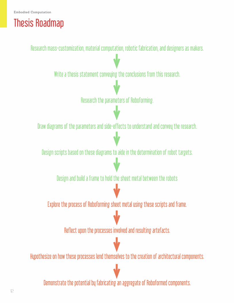
Research mass-customization, material computation, robotic fabrication, and designers as makers.
Write a thesis statement conveying the conclusions from this research.
Research the parameters of Roboforming.
Draw diagrams of the parameters and side-effects to understand and convey the research.
Design scripts based on these diagrams to aide in the determination of robot targets.
Design and build a frame to hold the sheet metal between the robots
Explore the process of Roboforming sheet metal using these scripts and frame.
Reflectupontheprocessesinvolvedandresultingartefacts.
Hypothesize on how these processes lend themselves to the creation of architectural components.
Demonstrate the potential by fabricating an aggregate of Roboformed components.
Thesis RoadmapEmbodied Computation
12
Embodied Computation is an investigation of Roboforming as it applies to design, fabrication, and architecture. Roboforming is a new rapid prototyping technique for forming sheet metal efficiently that allows the fabrication of complex unique surface geometries without the need for expensive dies by utilizing two industrial robots. (Bruninghaus, 1) There is sigificant potential in this forming process in the context of architecture which at its most base level can be applied to ideas of mass-customization and at its most abstract, a rethinking of how architecture is designed and concieved of. Mass-customization offers production of individual components at almost the price of mass production. (Scheurer, ”Materialising Complexity.”, 91) Roboforming, which follows this paradigm, is still largely unused in other manufacturing industries since it is not appropriate for mass-production in large quantities. (Meier, 37) However, I argue this trait makes Roboforming perfect for the production of architectural components, which are custom to their site.This thesis’ role in the advancement of Roboforming is to fill gaps in the research of engineers and material scientists, who admit there is no existing software to easily output tool-paths for Roboforming and thus, Roboforming “has not been applied to a large complex geometry yet.” (Meier, 4) In addition, 3D plasma-cutting of Roboformed parts has not been explored, and could offer new possibilities. (Meier, 4)This project will be realized through a feedback loop, as Menges describes or a Persistent Model as Ayres of sixteen*(makers) describes, of computational and physical tool-making, robotic fabrication, and analysis. This reseach differentiates itself from the work of engineers and material scientists, who mainly study methods to increase the accuracy of Roboforming, by focusing on issues of customized design and haptic responses that a formed part can generate in the context of architecture and at an architectural scale. Rather than seek to decrease deviations in the formed part, this project embraces the inaccuracies and side-effects and incorporates them in the design. The uniqueness of a formed part due to the inherent inaccuracy of Roboforming can actually add value to it. The materiality and method of manufacture play a tacit role in the response by the user. (Ayres, 221) Achim Menges argues that architecture attains its relevance “through the articulation of material arrangements and structures,” thus, “the way we conceptualize these material interventions- and particularly the technology that enables their construction - presents a fundamental aspect in how we (re)think architecture.” (Menges, “Integral Formation and Materialisation”, 198)
The interest in Roboforming stems from a broader scope of research that addresses ways to improve architecture’s specificity and offer architects more choice and thereby more control. Roboforming should not be dismissed from serious investigation out of nonconformity to the current ideals of dimensional accuracy and fully predetermined outcomes before a thorough evaluation of its potentials and implications. (Ayres, 222)
My background in robotic fabrication, architecture, and computational design will enable me to design a process chain for Roboforming which includes: constructing the blank holder, writing scripts to output tool-paths based on geometrical input, synchronizing two 6-axis industrial robots, and outputting an example of what Roboforming in capable in relation to customized architectural components.
A more detailed examination of Roboforming and its parameters and side-effects will provide useful insight into how the process works and lead to a richer, more informed design.
Thesis StatementIntroduction
13

1414

15
Roboforming Parameters

Types of Incremental Forming
A flat sheet of metal or plastic, known as a blank, is secured in a blank holder. A universal forming tool with a spherical head, follows the contours of the geometry to be formed, causing the sheet to be deformed along the tool-path. This is an efficient method, but causes inaccuracies and deviations from the desired geometry due in large part to the springback of the sheet.
A variation of AISF in which a backplate with the outlines of the desired geometry are fixed to the sheet on the opposite side of the tool-head. The backplate provides leverage at the initial crease of the form, reducing some of the deviations caused by springback. However, this method increases accuracy mostly at the periphery of the shape.
1/8 in”1/4 in”3/8 in”3/8 in”
Universal Forming ToolsSeconday Tools
Dapper PunchSupport ToolHeat Gun Straight Tapered Tipped
y
x
d
2x
2d
x
x
y
Blank Holder Universal Forming Tool B lank
1/8 in”1/4 in”3/8 in”3/8 in”
Universal Forming ToolsSeconday Tools
Dapper PunchSupport ToolHeat Gun Straight Tapered Tipped
y
x
d
2x
2d
x
x
y
Blank Holder Universal Forming Tool B lank
Backplate
Single Point Incremental Forming (SPIF):
Asymmetric Incremental Sheet Forming (AISF):
Embodied Computation
16
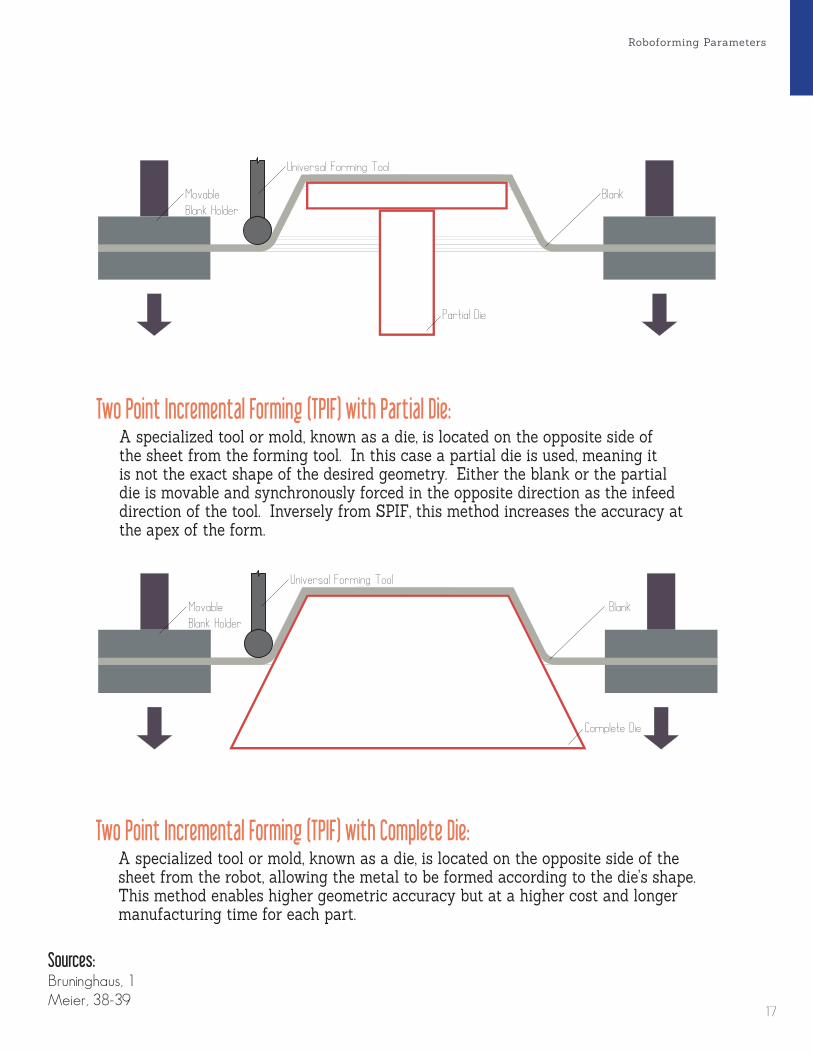
Roboforming Parameters
1/8 in”1/4 in”3/8 in”3/8 in”
Universal Forming ToolsSeconday Tools
Dapper PunchSupport ToolHeat Gun Straight Tapered Tipped
y
x
d
2x
2d
x
x
y
Movable
Blank Holder
Universal Forming Tool
Partia l Die
Blank
A specialized tool or mold, known as a die, is located on the opposite side of the sheet from the forming tool. In this case a partial die is used, meaning it is not the exact shape of the desired geometry. Either the blank or the partial die is movable and synchronously forced in the opposite direction as the infeed direction of the tool. Inversely from SPIF, this method increases the accuracy at the apex of the form.
A specialized tool or mold, known as a die, is located on the opposite side of the sheet from the robot, allowing the metal to be formed according to the die’s shape. This method enables higher geometric accuracy but at a higher cost and longer manufacturing time for each part.
1/8 in”1/4 in”3/8 in”3/8 in”
Universal Forming ToolsSeconday Tools
Dapper PunchSupport ToolHeat Gun Straight Tapered Tipped
y
x
d
2x
2d
x
x
y
Movable
Blank Holder
Universal Forming Tool
Complete Die
Blank
Sources:Bruninghaus, 1Meier, 38-39
Two Point Incremental Forming (TPIF) with Partial Die:
Two Point Incremental Forming (TPIF) with Complete Die:
17
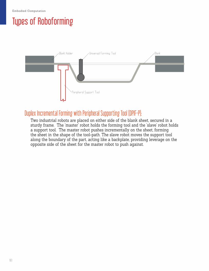
Types of Roboforming
Two industrial robots are placed on either side of the blank sheet, secured in a sturdy frame. The ‘master’ robot holds the forming tool and the ‘slave’ robot holds a support tool. The master robot pushes incrementally on the sheet, forming the sheet in the shape of the tool-path. The slave robot moves the support tool along the boundary of the part, acting like a backplate, providing leverage on the opposite side of the sheet for the master robot to push against.
1/8 in”1/4 in”3/8 in”3/8 in”
Universal Forming ToolsSeconday Tools
Dapper PunchSupport ToolHeat Gun Straight Tapered Tipped
y
x
d
2x
2d
x
x
y
Blank Holder Universal Forming Tool
Peripheral Support Tool
B lank
Duplex Incremental Forming with Peripheral Supporting Tool (DPIF-P):
Embodied Computation
18
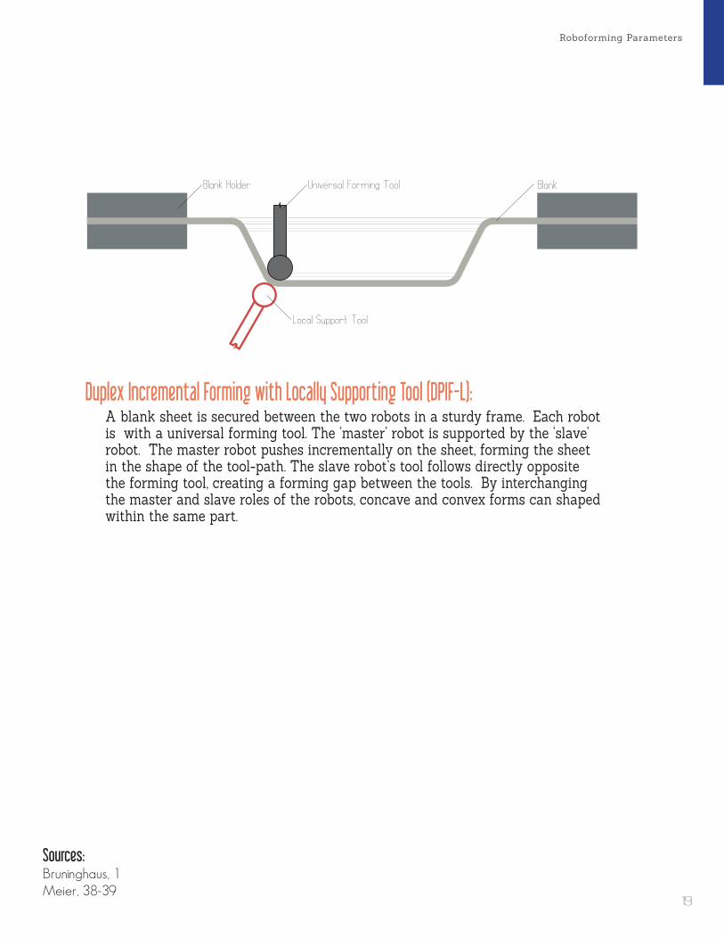
Roboforming Parameters
A blank sheet is secured between the two robots in a sturdy frame. Each robot is with a universal forming tool. The ‘master’ robot is supported by the ‘slave’ robot. The master robot pushes incrementally on the sheet, forming the sheet in the shape of the tool-path. The slave robot’s tool follows directly opposite the forming tool, creating a forming gap between the tools. By interchanging the master and slave roles of the robots, concave and convex forms can shaped within the same part.
1/8 in”1/4 in”3/8 in”3/8 in”
Universal Forming ToolsSeconday Tools
Dapper PunchSupport ToolHeat Gun Straight Tapered Tipped
y
x
d
2x
2d
x
x
y
Blank Holder
Local Support Tool
Universal Forming Tool B lank
Sources:Bruninghaus, 1Meier, 38-39
Duplex Incremental Forming with Locally Supporting Tool (DPIF-L):
19
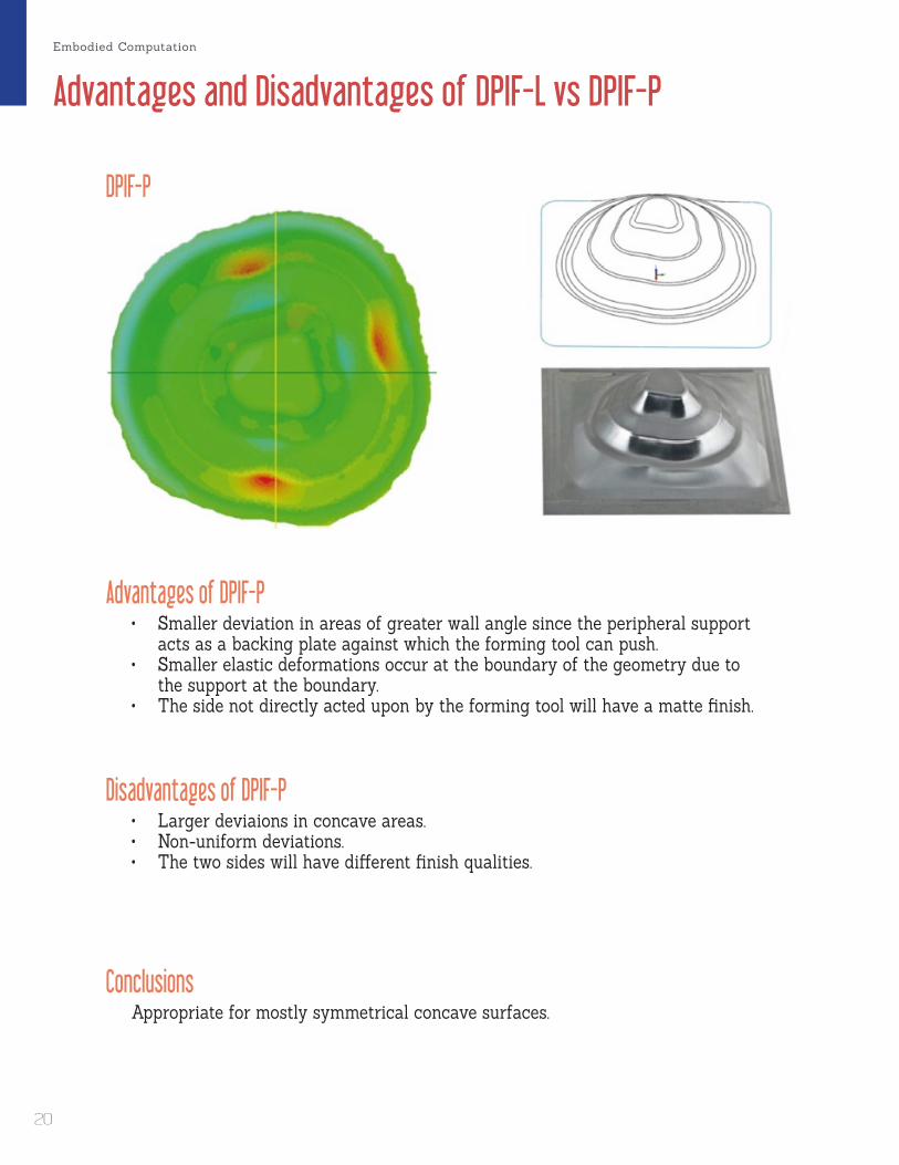
Advantages and Disadvantages of DPIF-L vs DPIF-P
• Smaller deviation in areas of greater wall angle since the peripheral support acts as a backing plate against which the forming tool can push.
• Smaller elastic deformations occur at the boundary of the geometry due to the support at the boundary.
• The side not directly acted upon by the forming tool will have a matte finish.
• Larger deviaions in concave areas.• Non-uniform deviations.• The two sides will have different finish qualities.
Appropriate for mostly symmetrical concave surfaces.
Advantages of DPIF-P
Disadvantages of DPIF-P
Conclusions
DPIF-P
Embodied Computation
20
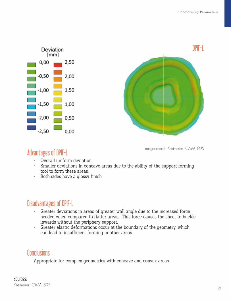
Roboforming Parameters
• Overall uniform deviation.• Smaller deviations in concave areas due to the ability of the support forming
tool to form these areas..• Both sides have a glossy finish.
• Greater deviations in areas of greater wall angle due to the increased force needed when compared to flatter areas. This force causes the sheet to buckle inwards without the periphery support.
• Greater elastic deformations occur at the boundary of the geometry, which can lead to insufficient forming in other areas.
Appropriate for complex geometries with concave and convex areas.
Advantages of DPIF-L
Disadvantages of DPIF-L
Conclusions
Sources:Kreimeier, CAM, 895
DPIF-L
Image credit: Kreimeier, CAM, 895
21

Causes of Deviations
1/8 in”1/4 in”3/8 in”3/8 in”
Universal Forming ToolsSeconday Tools
Dapper PunchSupport ToolHeat Gun Straight Tapered Tipped
y
x
d
2x
2d
x
x
y
1/8 in”1/4 in”3/8 in”3/8 in”
Universal Forming ToolsSeconday Tools
Dapper PunchSupport ToolHeat Gun Straight Tapered Tipped
y
x
d
2x
2d
x
x
yMaterial, forming geometry, infeed, velocity, stepdown, stepover, and tool-path type (contoured, stepped, or helical) affect the accuracy of the part.
Due to the regression of the elastic forming ratio, the formed sheet will rest in a state somewhere between the desired geometry and the original flat sheet. This springback force, F
S, is inherient in the thickness of the material.
Forming Parameters
Springback
FS
Embodied Computation
22

Roboforming Parameters
1/8 in”1/4 in”3/8 in”3/8 in”
Universal Forming ToolsSeconday Tools
Dapper PunchSupport ToolHeat Gun Straight Tapered Tipped
y
x
d
2x
2d
x
x
y
1/8 in”1/4 in”3/8 in”3/8 in”
Universal Forming ToolsSeconday Tools
Dapper PunchSupport ToolHeat Gun Straight Tapered Tipped
y
x
d
2x
2d
x
x
yForming forces, F
F, acting on the tool cause the robot to deflect from its
predetermined path. If a robots detects enough force against its tool-head, it will pull-back to reduce the forces.
Due to the 6 joints of the robot the tool-tip does not always end up exactly where it was planned. The domain of the positioning accuracy, R
Ac , can be as much
as several tenths of a millimeter. This is determined by the resolution of the kinematic solvers and the accuracy of the robot’s many joints.
Robot Compliance
Positioning Accuracy
Sources:Meier, 161
RAc
FF
23

Methods for Increasing Part Accuracy
(Meier, Accuracy, 7)
Deviations in normal direction of a truncated cone
Multiple FormingTo increase the accuracy of the final formed geometry, run the forming process twice. This is effective because on the first round, the forming forces can get very high, depending on the depth of the part. These high forming forces and robot compliance cause the robot to pull back and ultimately the tool tip ends up not as far as described in the program code. Once the sheet has been formed, the second forming process will have significantly lower stresses since the sheet is already deformed close to the desired result. This allows the robot to follow it’s input path more accuractly. The metal is also hardened in the first forming process due to strain hardening, so the metal is less able to bow and avoid the forming tool.
Step 1
Step 1
Step 2
Step 2
Ac t u a l Measured G e ome t ryDes i r e d G e ome t ry
F i n a l G e ome t ry
Embodied Computation
24

Roboforming Parameters
Adjustment VectorThis methods requires a feedback loop between sensors on the robot and tool-generation software. This could be done with finite element simulations of the forming process to predict deviations, but this is a time-consuming process, to the point where it is not viable with current software and hardware capabilities. Instead, a process of forming, scanning, adjusting the tool-path based on deviations, and forming again must be used. Rather than regerated the CAD geometry, it makes more sense to apply a spicific adjustment vector to each tool-path point. Ultimately, this means forming the part further out than the CAD geometry to accont for springback.
Sources:Meier, Accuracy, 1-7
TCPL
ADJ
LDEV
A c t u a l Measured G e ome t ry
Des i r e d G e ome t ry
Form i n g G e ome t ryP
E
PC
25

Maximizing Surface Quality
x
dyx
dy
Forming Parameters
Seconary Forming Tool
The appearance and roughness of both sides of the surface is dependent on the tool the forming tool’s diameter, d , stepdown, y , and stepover, x . There is a direct relationship between the the tool diameter and the smoothness of the surface. In addition, there is an inverse relationship between the infeed parameters, x and y , to the surface smoothness.
In AISF, the side of the surface which is acted upon directly by the forming tool has a glossy appearance. This side also has grooves and stratches due to the movement of the tool. The other side, which is not in direct contact with the forming tool, has a bumpy matte finish with an ‘orange peel’ effect caused by the stretching of the sheet. So in DPIF-L, where there is a forming tool on each side, the result is both sides have a glossy finish.
Secondary F o rm i n g Too l
Embodied Computation
26

Roboforming Parameters
x
dyx
dy
Lubricant
Dummy Sheet
Friction caused by the interaction between the forming tool and sheet is a main component of the surface quality. By applying lubricant such as tapping fluid, the friction forces are reduced and scratches are minimized.
Grooves caused by the tool can be prevented by layering an additional sheet on top of the sheet you wish to keep. This top sheet is known as a ‘dummy sheet’ and picks up all the tool marks while the lower sheet is formed indirectly by the deformation of the dummy sheet. As a result, the dummy is glossy on both sides and the lower sheet has a matte finish on both sides.
Sources:Bruninghaus, 2Meier, DPIF-L, 327
L ubr i c a n t
D ummy Shee t
27
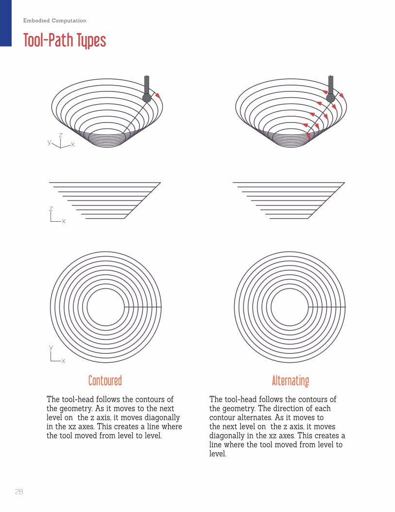
Tool-Path Types
The tool-head follows the contours of the geometry. As it moves to the next level on the z axis, it moves diagonally in the xz axes. This creates a line where the tool moved from level to level.
The tool-head follows the contours of the geometry. The direction of each contour alternates. As it moves to the next level on the z axis, it moves diagonally in the xz axes. This creates a line where the tool moved from level to level.
xz
y
x
z
x
y
xz
y
x
z
x
y
Contoured Alternating
Embodied Computation
28

Roboforming Parameters
The tool-head follows the contours of the geometry, but when it steps to the next level, it moves in the xy, then z axes, removing the line created by the tool as it moves from level to level.
The tool-head follows a continuous path outlining the shape of the geometry. The tool is always moving in the x, y, and z axes, creating a helix pattern in the formed part.
xz
y
x
z
x
y
xz
y
x
z
x
y
Stepped Helical
29
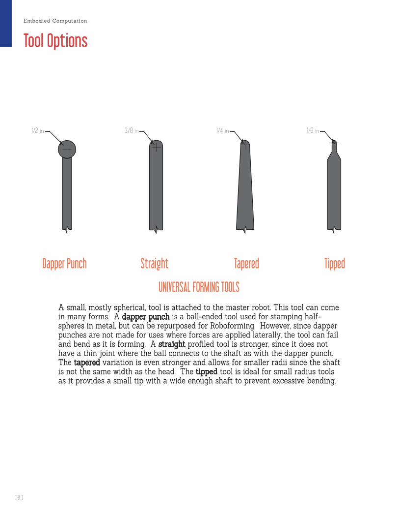
Tool Options
UNIVERSAL FORMING TOOLSA small, mostly spherical, tool is attached to the master robot. This tool can come in many forms. A dapper punch is a ball-ended tool used for stamping half-spheres in metal, but can be repurposed for Roboforming. However, since dapper punches are not made for uses where forces are applied laterally, the tool can fail and bend as it is forming. A straight profiled tool is stronger, since it does not have a thin joint where the ball connects to the shaft as with the dapper punch. The tapered variation is even stronger and allows for smaller radii since the shaft is not the same width as the head. The tipped tool is ideal for small radius tools as it provides a small tip with a wide enough shaft to prevent excessive bending.
Dapper Punch Straight Tapered Tipped
1/8 in1/4 in3/8 in1/2 in
Embodied Computation
30
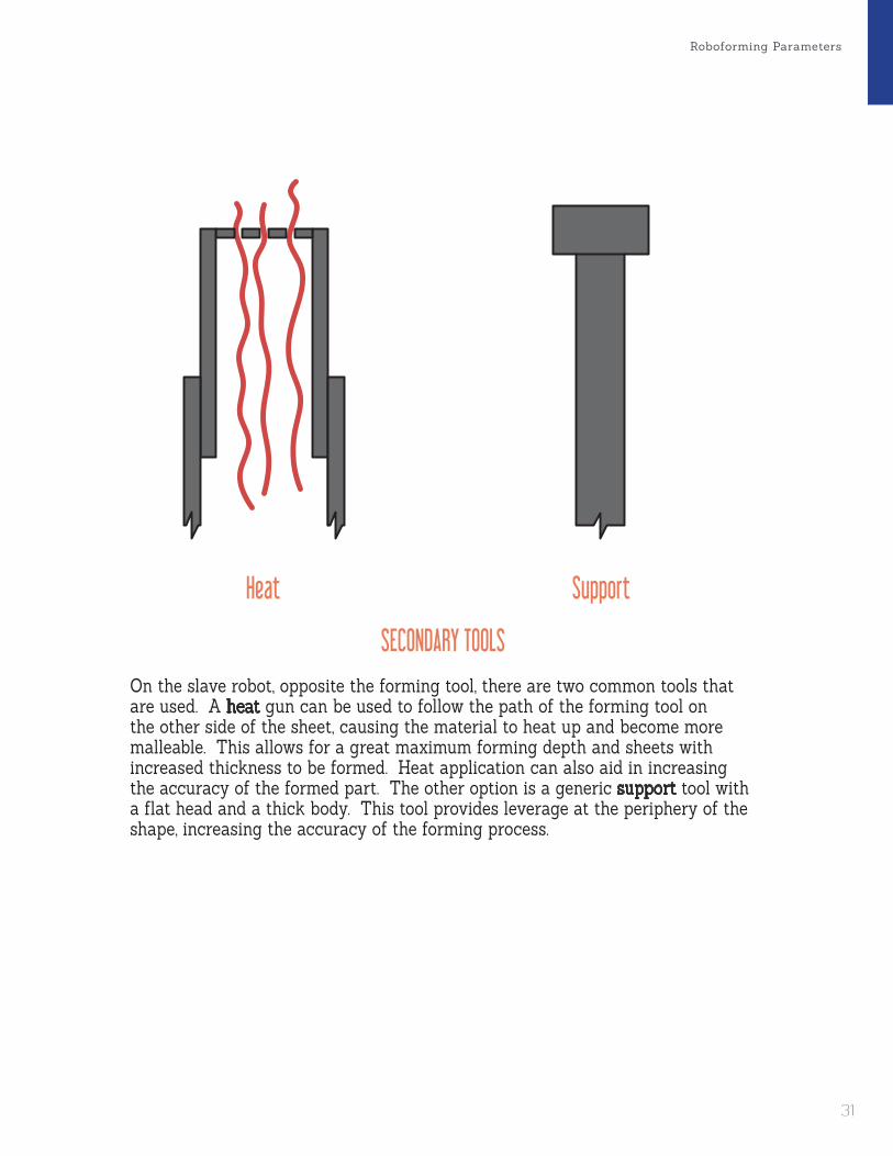
Roboforming Parameters
SECONDARY TOOLSOn the slave robot, opposite the forming tool, there are two common tools that are used. A heat gun can be used to follow the path of the forming tool on the other side of the sheet, causing the material to heat up and become more malleable. This allows for a great maximum forming depth and sheets with increased thickness to be formed. Heat application can also aid in increasing the accuracy of the formed part. The other option is a generic support tool with a flat head and a thick body. This tool provides leverage at the periphery of the shape, increasing the accuracy of the forming process.
Heat Support
31

Maximum Wall Angle
DPIF-LOne way to increase the maximum wall angle is to use a secondary support tool local to the forming tool. This provides additional force applied to the formed point, and greater leverage to form the sheet. Consequently, α
max increases by
about 12.5o for a new αmax
of about 77.5o.
Cosine’s LawSince the sheet is stretched by the forming process material thinning occurs. So there is a maximum wall angle, α
max that can be formed in a single step. Beyond
αmax
the sheet will tear. As the draw angle, α , of the forming tool increases, the sheet thickness at the formed point, t , decreases. For most materials, angles up to 65o can be formed. The thickness can be approximated by cosine’s law, defined as:t = t 0 × c o sαt = thickness at formed pointt 0 = initial sheet thicknessα = draw angle
t 0
t 0
t
t
α
α
t 0
t 0
Embodied Computation
32

Roboforming Parameters
Multiple Forming
Step 1
Step 2
If angles greater than amax need to be formed, a process known as multiple forming can be utilzied. In this process formed areas are formed twice by non-identical paths. The first pass forms the material up to the amax of the material. The second pass forms the desired final angle. This process even allows for angles greater than 90o to be formed, creating what would be considered undercuts in a milling process. Sources:
Bruninghaus, 2Meier, DPIF-L, 327-328
α> 90
33
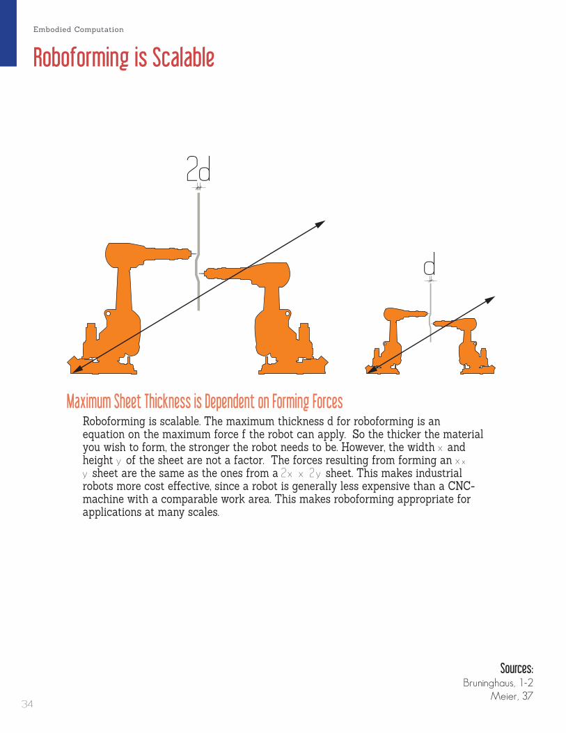
Roboforming is Scalable
Roboforming is scalable. The maximum thickness d for roboforming is an equation on the maximum force f the robot can apply. So the thicker the material you wish to form, the stronger the robot needs to be. However, the width x and height y of the sheet are not a factor. The forces resulting from forming an x × y sheet are the same as the ones from a 2 x x 2 y sheet. This makes industrial robots more cost effective, since a robot is generally less expensive than a CNC-machine with a comparable work area. This makes roboforming appropriate for applications at many scales.
d
2d
d
2d
Sources:Bruninghaus, 1-2
Meier, 37
Maximum Sheet Thickness is Dependent on Forming Forces
Embodied Computation
34

Roboforming Parameters
35
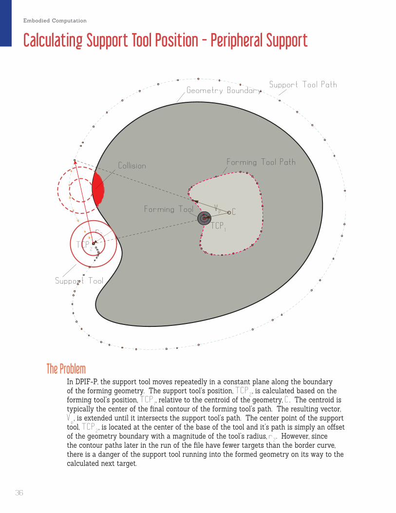
The ProblemIn DPIF-P, the support tool moves repeatedly in a constant plane along the boundary of the forming geometry. The support tool’s position, TCP
2, is calculated based on the
forming tool’s position, TCP1, relative to the centroid of the geometry, C . The centroid is
typically the center of the final contour of the forming tool’s path. The resulting vector, V
p, is extended until it intersects the support tool’s path. The center point of the support
tool, TCP2, is located at the center of the base of the tool and it’s path is simply an offset
of the geometry boundary with a magnitude of the tool’s radius, r2. However, since
the contour paths later in the run of the file have fewer targets than the border curve, there is a danger of the support tool running into the formed geometry on its way to the calculated next target.
VP C
F o rm i n g Too l P a t h
S u p por t Too l P a t h
C o l l i s i o n
S u p por t Too l
G e ome t ry B o u n dary
Form i n g Too l
T C P1
T C P2
r2
Calculating Support Tool Position - Peripheral SupportEmbodied Computation
36

Roboforming Parameters
The SolutionTo solve this problem a series of interpolation targets along the border curve from the current tool target to the next tool target. will need to be inserted into the Support Tool Path. What this ends up meaning is that the Support Tool Path will have more targets than the Forming Tool Path. This complicates the calculation of the synchronized times. However, a function can be written to calculate the new times based on this interpolation method.
VP
Sources:Kreimeier, CAD, 6-7
C
Form i n g Too l P a t h
S u p por t Too l P a t h
S u p por t Too l
I n t e r p o l a t i o n P o i n t s
G e ome t ry B o u n dary
Form i n g Too l
T C P1
T C P2
r2
37

Calculating Support Tool Position - Local Support
Zone for Local Support The center point of the supporting forming tool, TCP
2, needs to be along the
vector, VL, from the center point of the master forming tool, TCP
1, to the point of
contact, Pc. TCP2 is translated from TCP
1 along V
L with a magnitude, M
v, of:
Mv = r 1 + t + r 2
r 1 = radius of master forming toolt = thickness of formed sheetr2 = radius of supporting forming toolThis allows the supporting forming tool to be in a variety of positions and orientations. The shifting angle, γ
max, is bound between 0 o , when the tools are
directly opposite eachother, and Nα, the angle normal to the wall angle, α .
VL
r1
t
t
t0
t0
γmax
r2
TCP1
T C P2
γ
0 o
Nα
α
90 o
Embodied Computation
38

Roboforming Parameters
DividebyCurvaturetoIncreaseComputationalEfficiencyThe robots do not follow paths or curves but rather are instructed to go to a series of targets. The tool-head can only move is a straight line between two targets. Therefore, the resulting toolpath is a faceted polyline. To increase the accuracy and surface quality of the forming, a smaller step size is desired. The more targets, the higher the accuracy. However, it is a waste of the computer’s resources to place targets at every small interval as inevitably targets would be placed where they really were not needed. Ideally, there should be more targets in areas of high curvature, and fewer where the curvature is less.
Image credit: Meier, Accuracy, 5
Image credit: Kreimeier, CAM, 892
Sources:Meier, Accuracy, 5Kreimeier, CAM, 892
39

40

Scripts
41
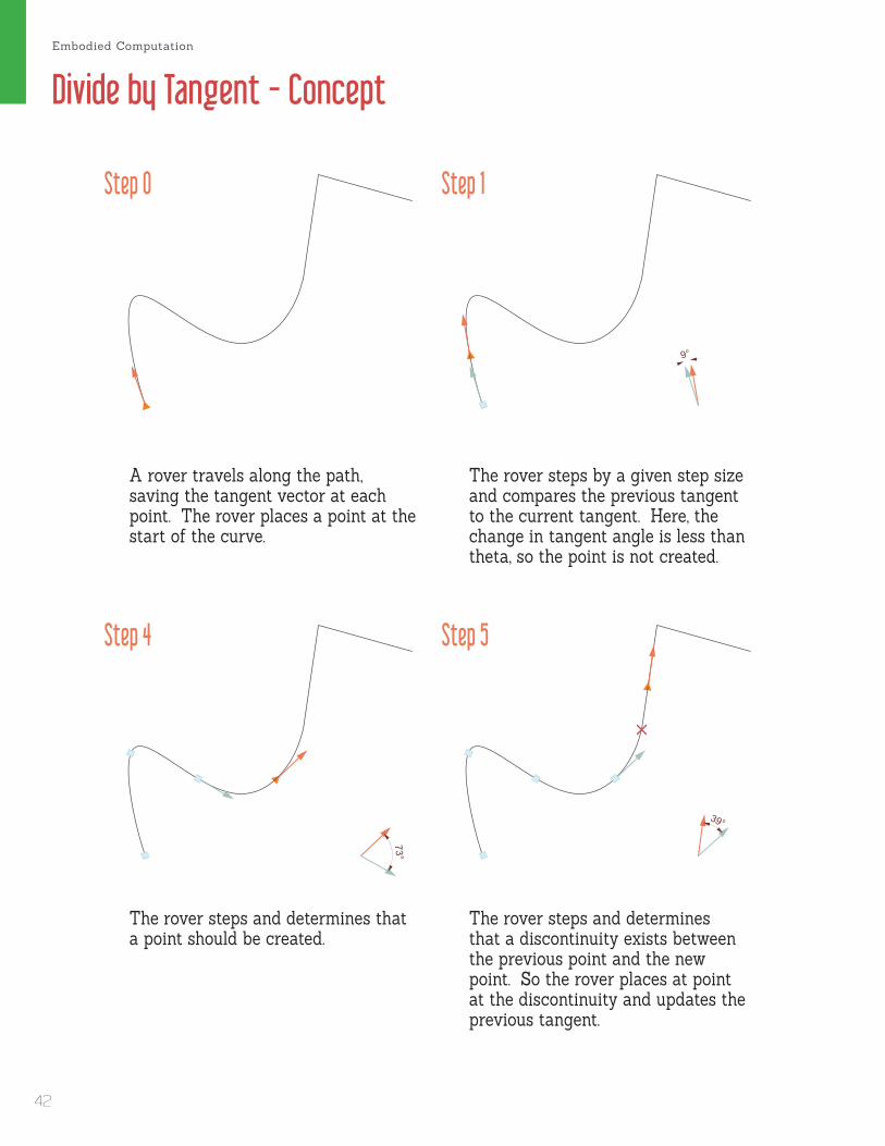
97°73°
99°
39°
40°9°
Divide by Tangent - Concept
Step 0
Step 4
Step 1
Step 5
A rover travels along the path, saving the tangent vector at each point. The rover places a point at the start of the curve.
The rover steps by a given step size and compares the previous tangent to the current tangent. Here, the change in tangent angle is less than theta, so the point is not created.
The rover steps and determines that a point should be created.
The rover steps and determines that a discontinuity exists between the previous point and the new point. So the rover places at point at the discontinuity and updates the previous tangent.
Embodied Computation
42

Scripts
97°73°
99°
39°
40°9°
Step 2
Step 6
Step 3
Step 7
toolpath calculated pointprevious tangent discontinuitycurrent tangent rover
The rover takes another step and compares this new tangent to the original tangent at the start of the curve. Since the angles changes by more than theta, a point is placed.
The rover steps and determines that a point should be created.
The rover steps and determines that a discontinuity exists between the previous point and the new point. So the rover places at point at the discontinuity and updates the previous tangent.
The rover places a point at the end.
43
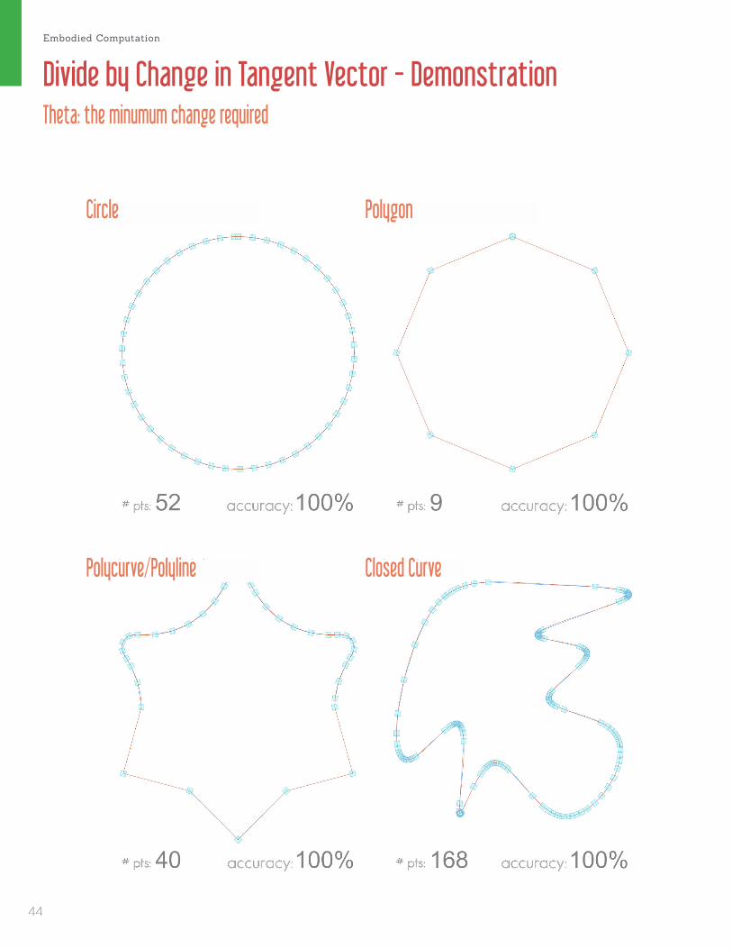
Divide by Change in Tangent Vector - DemonstrationTheta: the minumum change required
Circle
Polycurve/Polyline
Polygon
Closed Curve
Embodied Computation
44
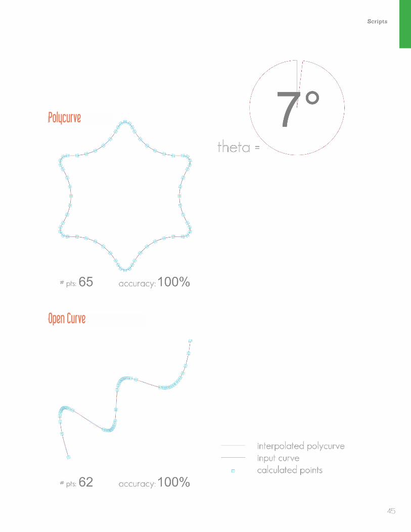
Scripts
Polycurve
Open Curve
45

Divide by Change in Tangent Vector - DemonstrationTheta: the minumum change required
Circle
Polycurve/Polyline
Polygon
Closed Curve
Embodied Computation
46

Scripts
Polycurve
Open Curve
47
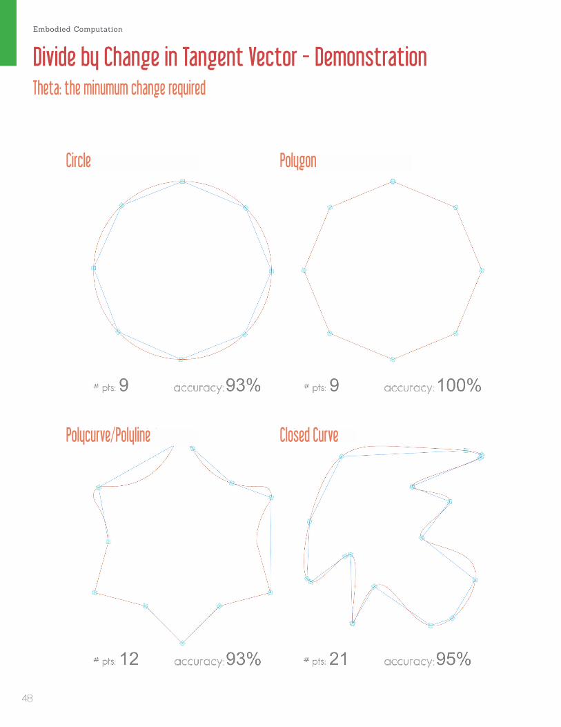
Divide by Change in Tangent Vector - DemonstrationTheta: the minumum change required
Circle
Polycurve/Polyline
Polygon
Closed Curve
Embodied Computation
48

Scripts
Polycurve
Open Curve
49

Divide by Change in Tangent Vector - DemonstrationTheta: the minumum change required
Circle
Polycurve/Polyline
Polygon
Closed Curve
Embodied Computation
50

Scripts
Polycurve
Open Curve
51
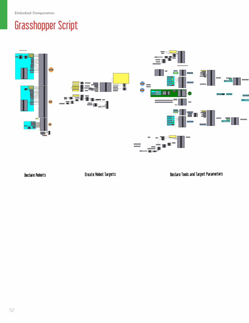
Grasshopper ScriptEmbodied Computation
52
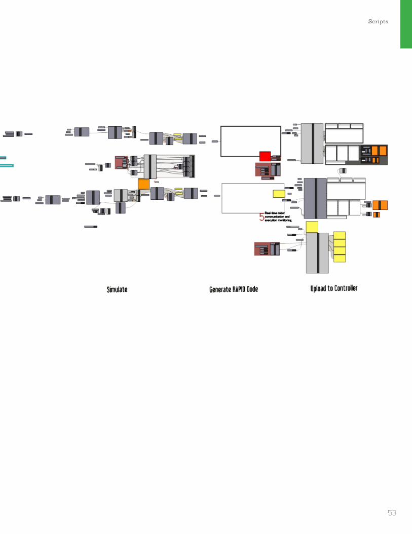
Scripts
53

Orientation Planes Component
The Orientation Planes component calculates the tool-path targets for the two robots. The goal of this compoenent is for it to be a safe, error-handling script that anyone with a basic knowledge of grasshopper can use without worrying about whether they are going to break the robots. An additional goal is to open source it and make it available to other students and fabricators to add additional functions. In order to realize this goal it is important that the code be clean and easy for even a novice programmer to understand and modify.
sheetThickness : doubleInitial thickness of the sheet metal
to be formed.
formingToolDiam : doubleDiameter of the forming tool’s tip.
supportToolDiam : doubleDiameter of the support tool’s tip.
stepdown : doubleInterval used to contour the
geometry.debug : stringErrors and Print statements.formingGeometry : Brep
Brep to be formed.formingTargets : PlaneThe targets the robot will follow in order.
startPt : Point3dApproximate starting point for the rool-path. Also determines
the seam between contours.
velocity : doubleMaximum velocity the robot will
move by.
formingTimes : doubleTimes for each forming target.
supportTimes : doubleTimes for each support target.
theta : doubleMinimum change in tangent
vector for target creation
supportTargets : PlaneThe minimum change in tangent vector for target creation
type : intThe support type.
0 = No Support1 = Local Support
2 = Peripheral Suppot
J6EndPt : Point3dJ6EndPt of the support robot
Embodied Computation
54

Scripts
55
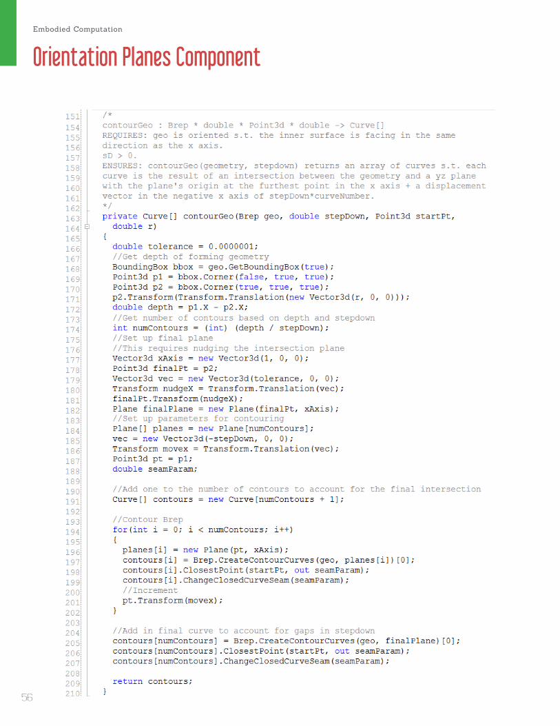
Orientation Planes ComponentEmbodied Computation
56

Scripts
57

Orientation Planes ComponentEmbodied Computation
58

Scripts
59

Orientation Planes ComponentEmbodied Computation
60
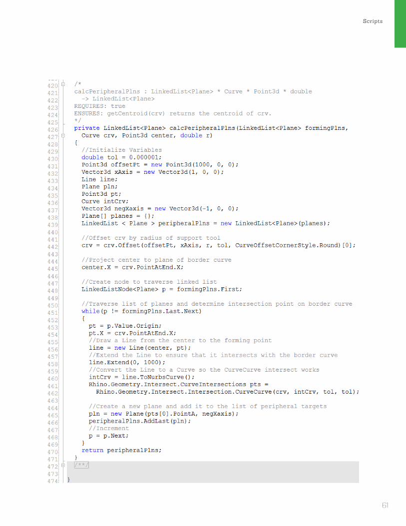
Scripts
61

Robot Simulation - Local SupportEmbodied Computation
62

Scripts
63
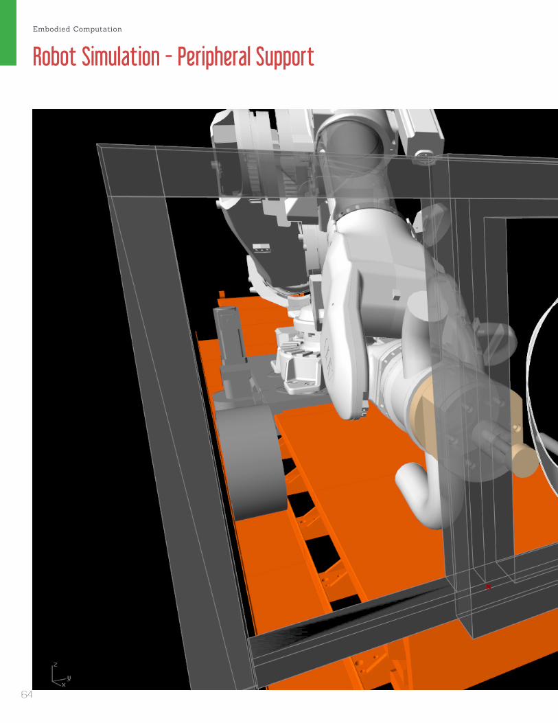
Robot Simulation - Peripheral SupportEmbodied Computation
64

Scripts
65

66

Tools
67

Forming ToolsDesign
Support ToolAlex Fischer11/20/2013 Scale: 1/2” = 1”
5 -1
/2"
0
- 1/2
"
1"
R 1"
6"
R 0 - 3/8"
2"
0 - 3/4"0 - 3/4"
8 -1
/2"
R 0
- 3/1
6"
R 0
- 3/8
"
8 -1
/2"
Support ToolAlex Fischer11/20/2013 Scale: 1/2” = 1”
5 -1
/2"
0
- 1/2
"
1"
R 1"
6"
R 0 - 3/8"
2"
0 - 3/4"0 - 3/4"
8 -1
/2"
R 0
- 3/1
6"
R 0
- 3/8
"
8 -1
/2"
Support ToolAlex Fischer11/20/2013 Scale: 1/2” = 1”
5 -1
/2"
0
- 1/2
"
1"
R 1"
6"
R 0 - 3/8"
2"
0 - 3/4"0 - 3/4"
8 -1
/2"
R 0
- 3/1
6"
R 0
- 3/8
"
8 -1
/2"
Support ToolForming Tools
Two forming tools were made from A2 Tool Steel. A diameter of 3/4” was chosen as a healthy medium between the thickness needed to prevent the tool from bending while still within a reasonable cost range. The support tool is also made from the 3/4” rod in order to standardize the connection to the robot. Ideally the tools would be as long as possible to reduce the chance of the robot joint colliding with the forming geometry. However the longer the tool, the more likely it is to break. The tools were made on a metal lathe and heat-treated to increase their strength.
Embodied Computation
68

Tools
A2 Tool Steel 3/4” Rods
Lathe Turning
Result
Machining Process
69

Tool Holder
38.1
0
109.
19
149.86
149.86
185.
42
R9.53R28.58
R92.71R5.00
R8.50
R8.50
R5.00
10.00 109.19185.42
17.00
Forming Tool HolderAlex Fischer11/20/2013 Scale: .5mm = 1mm
38.1
0
109.
19
149.86
149.86
185.
42
R9.53R28.58
R92.71R5.00
R8.50
R8.50
R5.00
10.00 109.19185.42
17.00
Forming Tool HolderAlex Fischer11/20/2013 Scale: .5mm = 1mm
38.1
0
109.
19
149.86
149.86
185.
42
R9.53R28.58
R92.71R5.00
R8.50
R8.50
R5.00
10.00 109.19185.42
17.00
Forming Tool HolderAlex Fischer11/20/2013 Scale: .5mm = 1mm
38.1
0
109.
19
149.86
149.86
185.
42
R9.53R28.58
R92.71R5.00
R8.50
R8.50
R5.00
10.00 109.19185.42
17.00
Forming Tool HolderAlex Fischer11/20/2013 Scale: .5mm = 1mm
units: millimetersTool Holder - Drawings
Tool Holder
Top
Front
Axo
Right
Design
The mechanism for holding the forming and support tools is straighforward. A 3” shaft with a set-screw secures the tool to the holder. The holder is bolted to the ATI AC-110 Tool Changer attached to joint 6 of both robots via 6 holes in the base of the tool holder. The manufacturing process involved turing a 7-1/2”x6” block of Multipirpose 6061 Aluminum on a lathe, then milling the holes for the bolts.
Embodied Computation
70

Tools
Machining Process
Lathe
Mill
71

72

73
The Frame
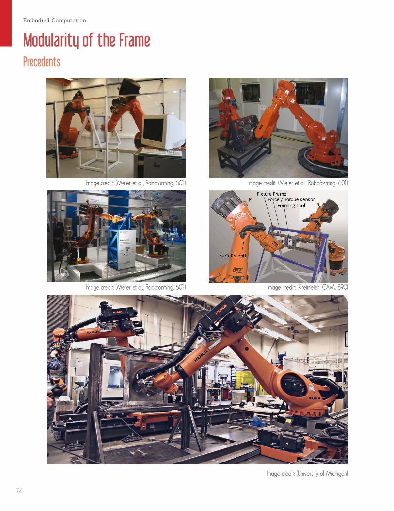
Modularity of the FramePrecedents
Image credit: (University of Michigan)
Image credit: (Meier et al., Roboforming, 601)
Image credit: (Kreimeier, CAM, 890)
Image credit: (Meier et al., Roboforming, 601)
Image credit: (Meier et al., Roboforming, 601)
Embodied Computation
74
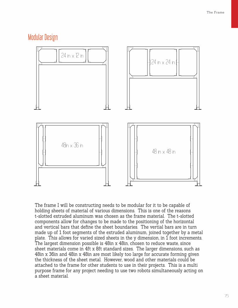
The Frame
Modular Design
The frame I will be constructing needs to be modular for it to be capable of holding sheets of material of various dimensions. This is one of the reasons t-slotted extruded aluminum was chosen as the frame material. The t-slotted components allow for changes to be made to the positioning of the horizontal and vertical bars that define the sheet boundaries. The vertial bars are in turn made up of 1 foot segments of the extruded aluminum, joined together by a metal plate. This allows for varied sized sheets in the y dimension, in 1 foot increments. The largest dimension possible is 48in x 48in, chosen to reduce waste, since sheet materials come in 4ft x 8ft standard sizes. The larger dimensions, such as 48in x 36in and 48in x 48in are most likely too large for accurate forming given the thickness of the sheet metal. However, wood and other materials could be attached to the frame for other students to use in their projects. This is a multi purpose frame for any project needing to use two robots simultaneously acting on a sheet material.
24 in x 12 in24 in x 24 in
48in x 36 in48 in x 48 in
24 in x 12 in24 in x 24 in
48in x 36 in48 in x 48 in
24 in x 12 in24 in x 24 in
48in x 36 in48 in x 48 in
24 in x 12 in24 in x 24 in
48in x 36 in48 in x 48 in
75

Sheet Attachment Detail
Secured Sheet
Having worked with sheet forming before, and being aware of the challenges with attachment, I have come up with what I believe to be an ideal solution. I reduced the number of holes that need to be drilled into the metal sheet down to 4 due to the energy and time needed to drill into metal. 4 alignment holes are mostly used to ensure the sheet is secured in the same place each time. Toggle clamps which have a clamping force of 500 lbs. do the real holding work These are ideal as they are inexpensive and have a low profile, so the robot does not collide with the clamps. These clamps are screwed into a 1/5 inch wood frame that matches the dimensions of the blank. Wood was chosen as the frame material as it is easy and relatively inexpensive to mill custom dimensioned parts as needed. The wooden backplate also provides additional leverage since the extruded aluminum stand has rounded edges. The toggle clamps act upon a thin wooden shim that serves merely to disperse the force across the length of the sheet. Screw-in t-nuts are slide into place and recieve 1/4 inch screws which hold the wood frame to the extruded aluminum stand.
Embodied Computation
76
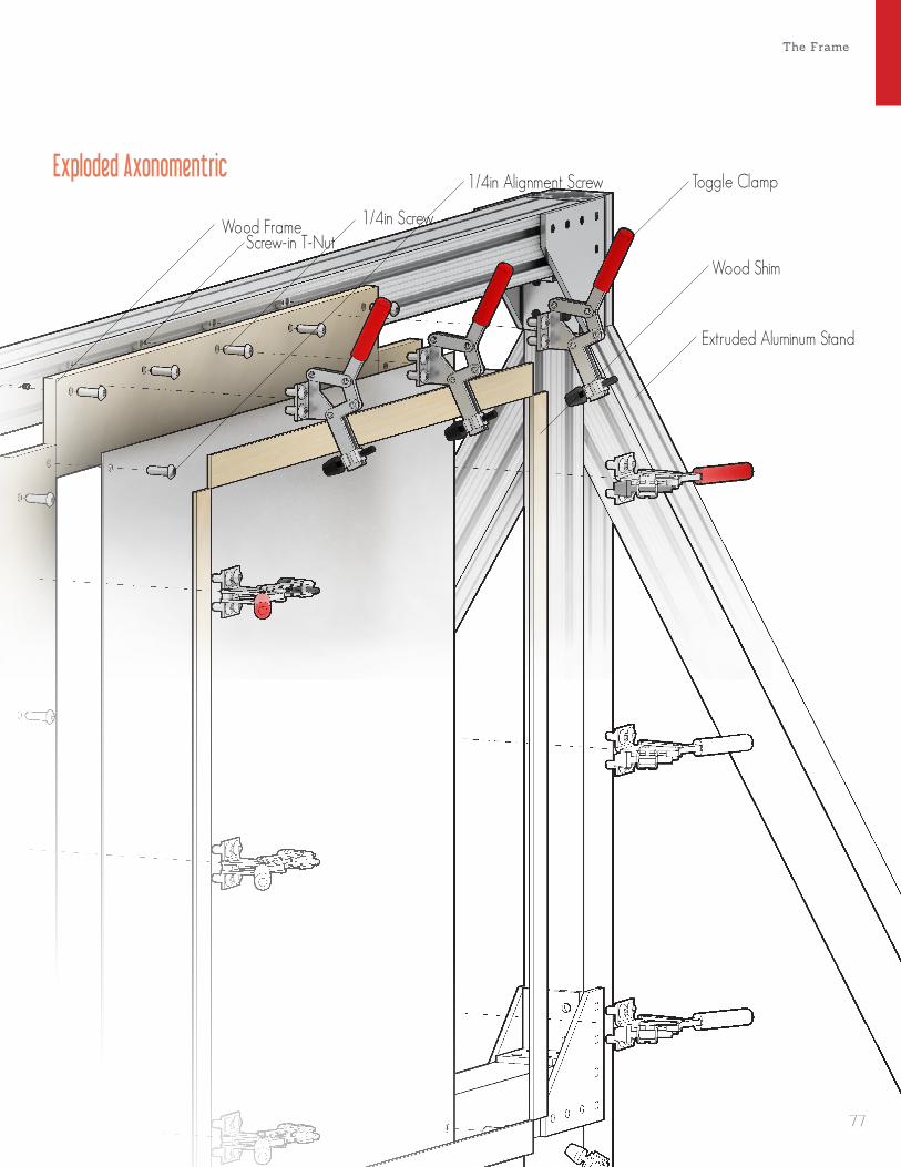
The Frame
Exploded Axonomentric
Extruded Aluminum Stand
Wood Shim
Toggle Clamp1/4in Alignment Screw
1/4in ScrewScrew-in T-Nut
Wood Frame
77
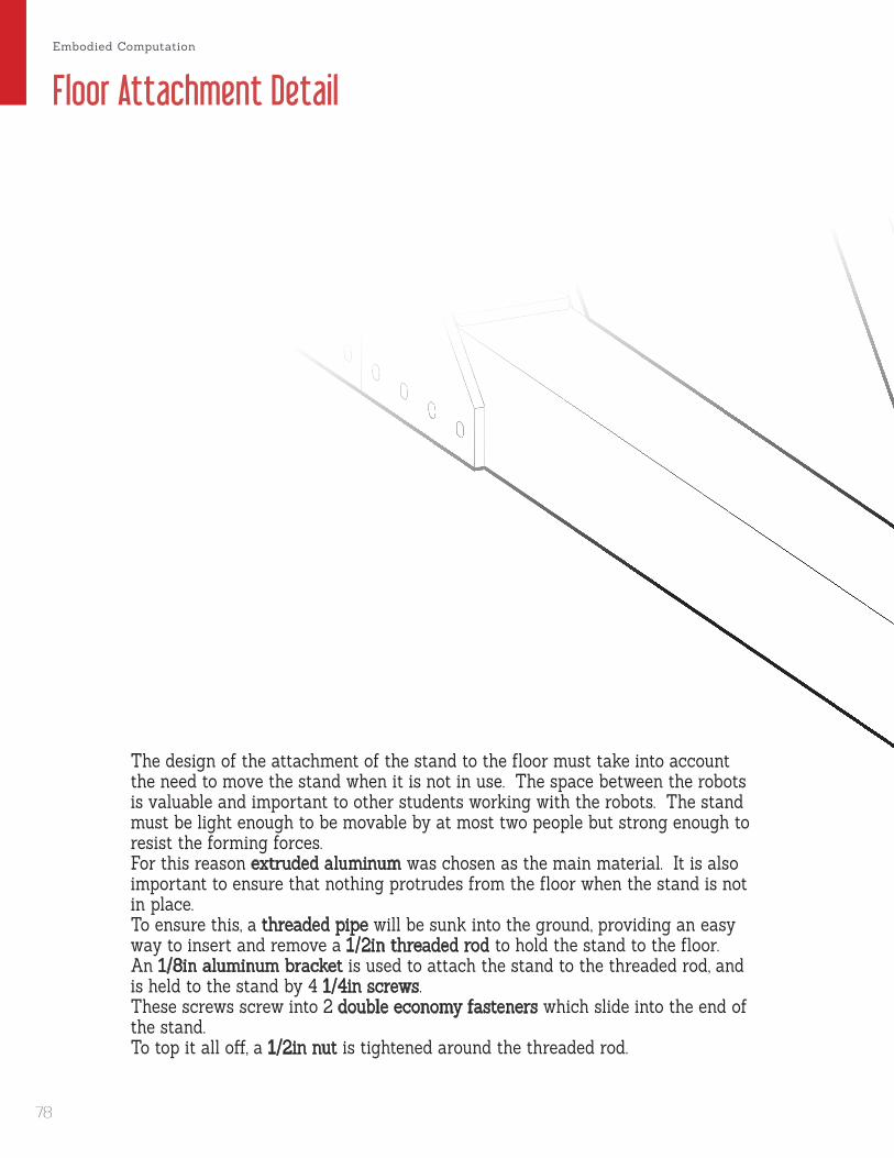
Floor Attachment Detail
The design of the attachment of the stand to the floor must take into account the need to move the stand when it is not in use. The space between the robots is valuable and important to other students working with the robots. The stand must be light enough to be movable by at most two people but strong enough to resist the forming forces. For this reason extruded aluminum was chosen as the main material. It is also important to ensure that nothing protrudes from the floor when the stand is not in place. To ensure this, a threaded pipe will be sunk into the ground, providing an easy way to insert and remove a 1/2in threaded rod to hold the stand to the floor. An 1/8in aluminum bracket is used to attach the stand to the threaded rod, and is held to the stand by 4 1/4in screws. These screws screw into 2 double economy fasteners which slide into the end of the stand. To top it all off, a 1/2in nut is tightened around the threaded rod.
Embodied Computation
78

The Frame
Exploded Axonomentric
1/4in Screw
1/8in Aluminum
Bracket
1/2in Threaded Rod
1/2in Nut
Extruded Aluminum Stand
Double Economy Fastener
1/2in Threaded Pipe
79
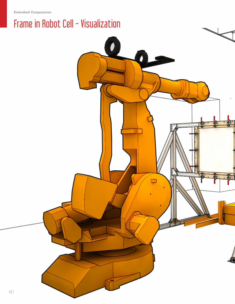
Frame in Robot Cell - VisualizationEmbodied Computation
80
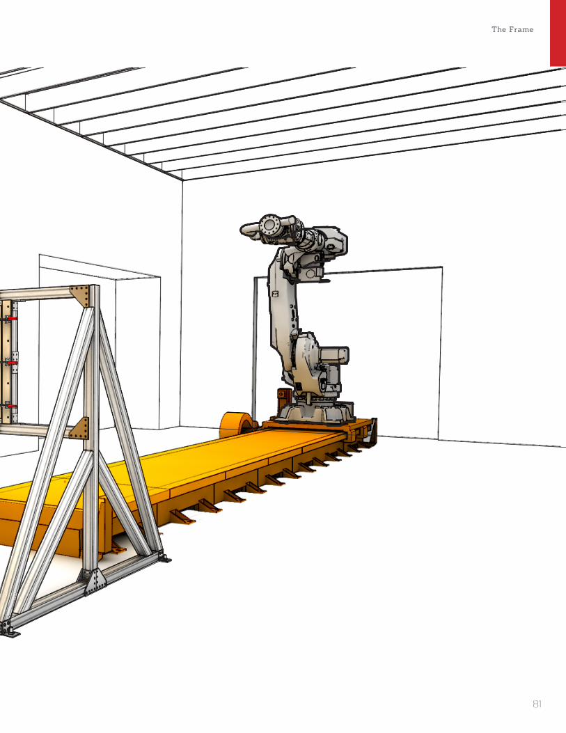
The Frame
81

82

Precedents
83

per-Forming - Incremental Sheet Formed Claddingby Jake Newsume at the University of Michigan, 2013
Submission for Tex-Fab’s Skin Competition Image credit: (Newsumme)
Embodied Computation
84

Tools
Ribbing Typologies“Throughout the development of the physical and digital tools for this process, feedback has constantly been taken and given between design and fabrication. These parameters are being used in the design to influence the metal skin’s global curvatures, local subdivision, and surface articulations to increase forming accuracy. The metal formed panels have been analyzed using 3D scanning technologies to understand where the structural ribs are needed for stabilization. The formed ribs are used as dynamic corrugations across the aggregation which makes a structured skin that identifies panel location.” (Newsumme)
No Ribbing
Edge to Center Ribbing
Diagonal Ribbing
Global Linear Ribbing
Image credit: (Newsumme)
85

Robot Assisted Sheet Metal Shaping - Hammer-Formed Claddingby Lik Hang Gu at the Harvard GSD, 2013
Submission for Tex-Fab’s Skin CompetitionImage credit: (Gu)
Scotch York Mechanism for the HammerRobot working senario
Patterns
Embodied Computation
86

Tools
Patterning Typologies Image credit: (Gu)
Pattern 1
Pattern 3
Pattern 2
Pattern 4
The hammering of sheet metal is much the the process of pointilism in drawing. One by one a robotic hammer punches the sheet at inputed points. There are many variations of this method which lead to decidedly different tacticle qualities. The result looks like a stiched cusion and the tool-path creates an ornamental aspect to each piece. “The sand base is designed to be able to adjust the hollow space under the sheet metal in order to allow further punching after sands are fully packed. Pattern followed by the curves generated in modeling software and translated into RAPID code for ABB robotic arm.” (Gu)
87

Responsive Skin - Incremental Sheet Formed Moldsby Brian Cadiz, Gabriel Huerta, and Joseph Mathias at UCLA and Aalto University
Shingles
Visualization
Fabrication
Shingle Typologies
Image credit: (Cadiz et al)
Embodied Computation
88
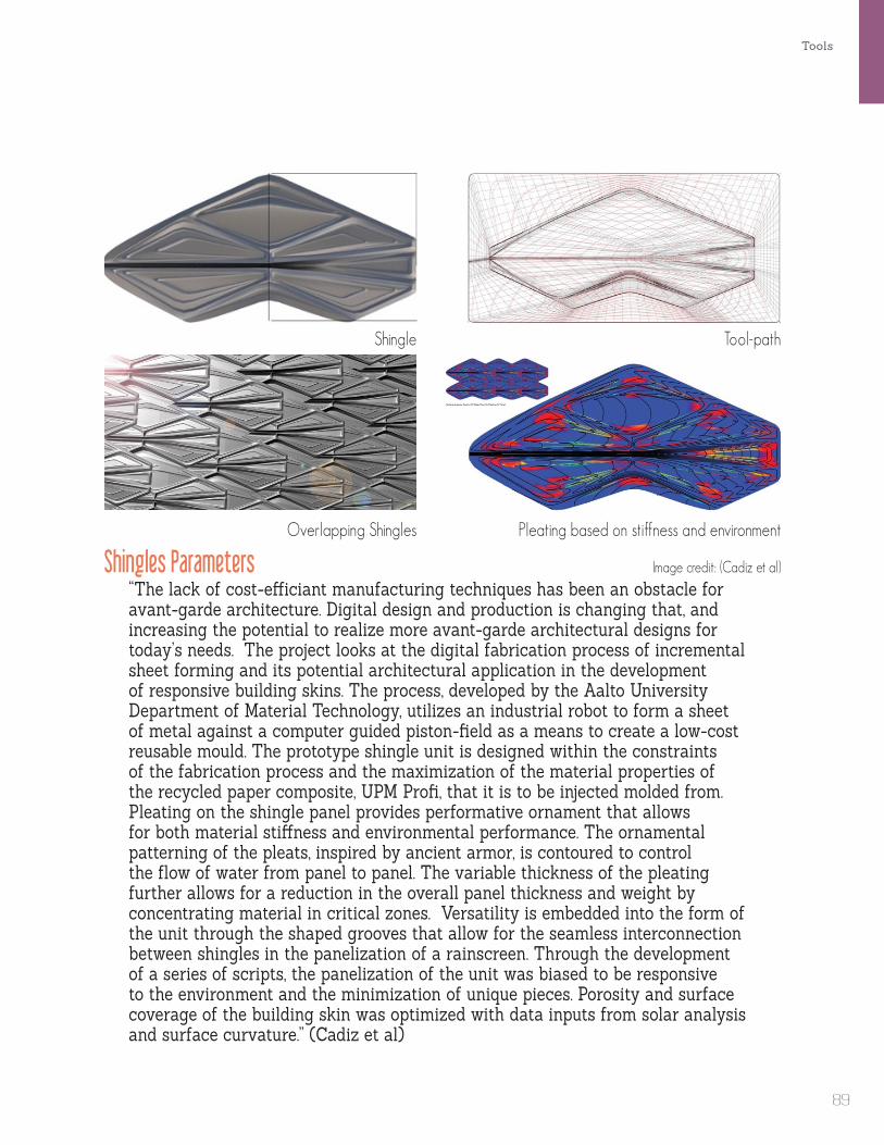
Tools
Shingles Parameters“The lack of cost-efficiant manufacturing techniques has been an obstacle for avant-garde architecture. Digital design and production is changing that, and increasing the potential to realize more avant-garde architectural designs for today’s needs. The project looks at the digital fabrication process of incremental sheet forming and its potential architectural application in the development of responsive building skins. The process, developed by the Aalto University Department of Material Technology, utilizes an industrial robot to form a sheet of metal against a computer guided piston-field as a means to create a low-cost reusable mould. The prototype shingle unit is designed within the constraints of the fabrication process and the maximization of the material properties of the recycled paper composite, UPM Profi, that it is to be injected molded from. Pleating on the shingle panel provides performative ornament that allows for both material stiffness and environmental performance. The ornamental patterning of the pleats, inspired by ancient armor, is contoured to control the flow of water from panel to panel. The variable thickness of the pleating further allows for a reduction in the overall panel thickness and weight by concentrating material in critical zones. Versatility is embedded into the form of the unit through the shaped grooves that allow for the seamless interconnection between shingles in the panelization of a rainscreen. Through the development of a series of scripts, the panelization of the unit was biased to be responsive to the environment and the minimization of unique pieces. Porosity and surface coverage of the building skin was optimized with data inputs from solar analysis and surface curvature.” (Cadiz et al)
Image credit: (Cadiz et al)
Tool-path
Overlapping Shingles
Shingle
Pleating based on stiffness and environment
89

The pre-elementing happens according to the chosen folding structure (longitudinal or facet-like). Metal pyramids with a hexagonal base area on the outer and a triangular base area on the inner site evolve from a double-layered facet-like folding. The softwaretool processes the individual metal pyramids for the CNC controlled sheet metal forming with the help of software that translates the geometry of the free-form into the data to control the CAM production (computer aided manufacturing). All different parts are labeled to assure a correct typological erection.” (Trautz and Herkath, 10)
Folded Plate Structures - Two Point Incremental Formed Panelsby Univ.-Prof. Dr.-Ing Martin Trautz, Dipl.-Ing. Ralf Herkrath at RWTH Aachen University, 2009
Image crecit: (Trautz and Herkath, 10)
Image crecit: (Trautz and Herkath, 10)
Double-Layered Facet-Like Folding Structure
Embodied Computation
90

Tools
Assembly Process
“The principle of folding structures is an established principle of construction in nature whose potential has rarely been used in architecture. Based on folding structures, high-stressed and wide-spanning light weight structures can be realised. More than the complex requirements for their constructive detailing, the limited possibilities to describe them geometrically with mathematical geometrical functions have constraint their realisation. Numerical digital methods annul this limitation by making the tessellation and triangulation of arbitrary shapes possible. Due to this method, almost any folding structure can be constructed (Trautz [7]).After the development of the software tool and after the first successful shaping, the research has now the aim to approach the application of folding structures in context of the sustainable use of material and to gain new impulses for this principle of structural shaping. Additionally, new ideas of the building process for free-forms should be generated which could also serve as helpful suggestions for other engineering disciplines.” (Trautz and Herkath, 12)
“The different metal pyramids are assembled to buildings elements which are to be erected on site. The assembling of the elements is guaranteed by overlapping of the different metal sheets.” (Trautz and Herkath, 11)
Image crecit: (Trautz and Herkath, 12)
91
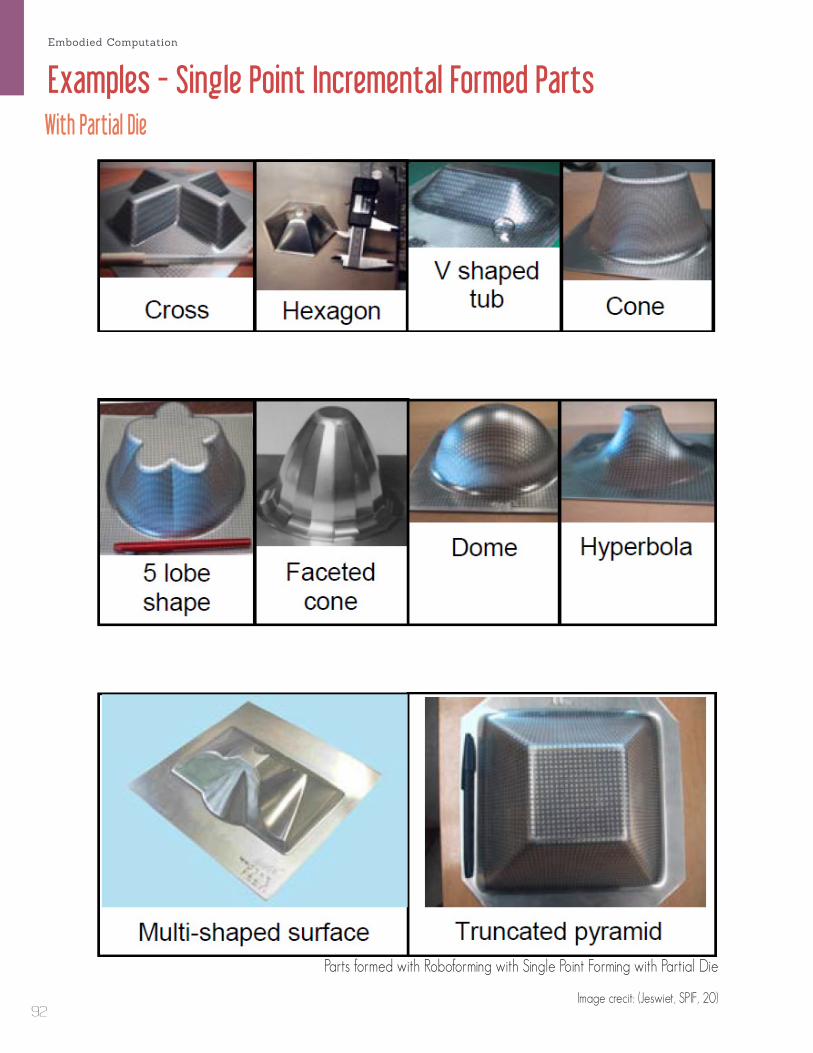
Examples - Single Point Incremental Formed PartsWith Partial Die
Parts formed with Roboforming with Single Point Forming with Partial Die
Image crecit: (Jeswiet, SPIF, 20)
Embodied Computation
92

Tools
Comparison of SPIF vs Roboforming with Local Support
Part formed with Single Point Incremental Forming
Part formed with Roboforming with Local Support
Image crecit: (Buff et al., Accuracy, 153)93

Examples - Roboformed Parts - Local SupportConcave and Convex
Parallel Forming
Sequential FormingImage crecit: (Malhotra , Accumulative-DSIF, 253)
Embodied Computation
94
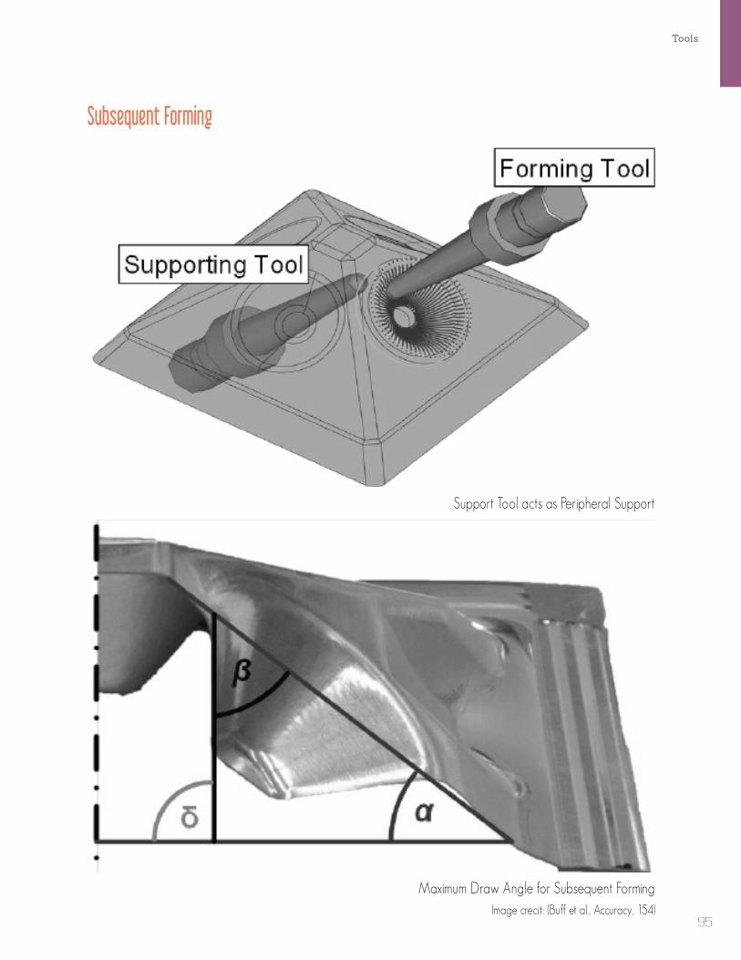
Tools
Subsequent Forming
Support Tool acts as Peripheral Support
Maximum Draw Angle for Subsequent FormingImage crecit: (Buff et al., Accuracy, 154)
95

Examples - Roboformed Parts - Peripheral SupportPeripheral Support Pieces
Wierd Bean Thing
Twisted Hexigon
Image crecit: (Meier et al., Tool Path, 149)
Embodied Computation
96

Tools
Comparison of Formability - Peripheral Support vs Local Support
Point of Failure with Peripheral Support
Point of Failure with Local Support
Image crecit: (Meier et al., DPIF, 330)97
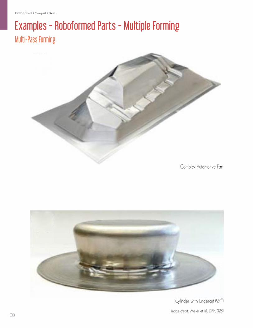
Examples - Roboformed Parts - Multiple FormingMulti-Pass Forming
Complex Automotive Part
Cylinder with Undercut (97
o)
Image crecit: (Meier et al., DPIF, 328)
Embodied Computation
98

Tools
Multiple Forming with Stabilization Surface
Hemisphere
3 Step Forming Process
Stabilization Surface
Image crecit: (Kreimeier, Accuracy, 859)99

Incremental Sheet Formed Prototype - ProcessBy Alex Fischer and Matt Adler at Carnegie Mellon University, 2013
Incremental Sheet Forming
2nd Incremental Sheet Forming
Incremental Sheet Forming - Result
2nd Incremental Sheet Forming - Result
Step 1
Step 5
Step 2
Step 6
Embodied Computation
100
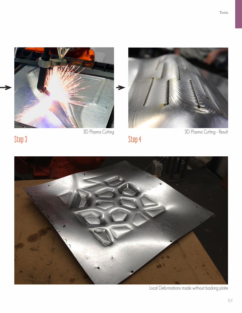
Tools
Local Deformations made without backing plate
3D Plasma Cutting 3D Plasma Cutting - Result
Step 3 Step 4
101

102

Experiments
103

Tool-path Variation
xz
y
x
z
x
y
xz
y
x
z
x
y
Contoured
????????
Alternating
Custom Toolpath Types
Toolpath resulting from divByDeltaTan
divByDeltaTan causes irregular spaced targets which influences the appearance of the formed part.
????????
xz
y
x
z
x
y
xz
y
x
z
x
y
Stepped Helical
FabricationImage credit: (Cadiz et al)
Ornamental Tracer Ribs
Figure Ground Mill File
Path Responsive Surface Milling - Leaves Style
? ?
Embodied Computation
104

Experiments
Ornamental Tracer Ribs
Figure Ground Mill File
Path Responsive Surface Milling - Leaves Style
Path Responsive Surface Milling - Cloth Style
Edge to Center Ribbing
Global Linear RibbingImage credit: (Newsumme)
Image credit: (Newsumme)
Image credit: (subdv.com)
Image credit: (Skylar Tibbits)
Image credit: (Skylar Tibbits)
105

3D Plasma Cutting of Formed PartsPrototype by Alex Fischer and Matt Adler, Carnegie Mellon University, 2013
3D Plasma Cutting - Calibration
Plasma Cuts Closeup - Interaction with Toolpath
3D Plasma Cutting - Arc Firing
Incrementally Form -> 3D Plasma Cut -> Incrementally Form
Embodied Computation
106
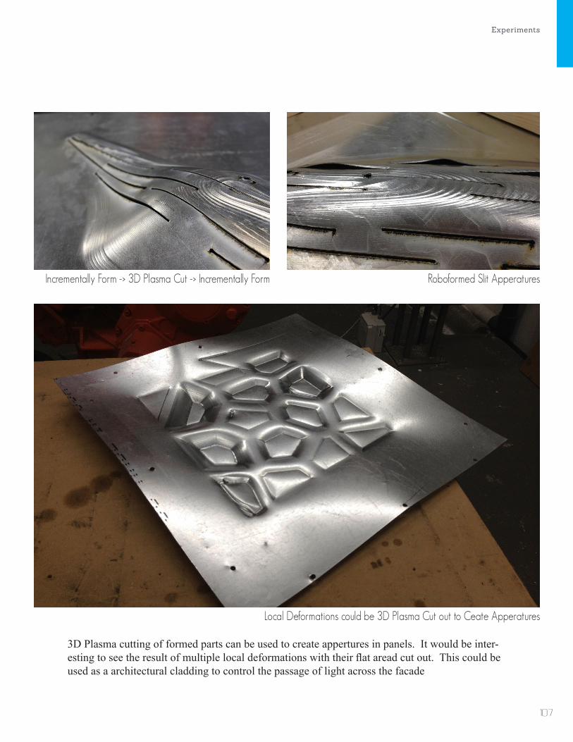
Experiments
Incrementally Form -> 3D Plasma Cut -> Incrementally Form Roboformed Slit Apperatures
Local Deformations could be 3D Plasma Cut out to Ceate Apperatures
3D Plasma cutting of formed parts can be used to create appertures in panels. It would be inter-esting to see the result of multiple local deformations with their flat aread cut out. This could be used as a architectural cladding to control the passage of light across the facade
107
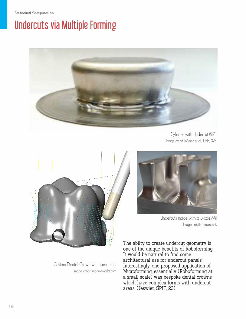
Cylinder with Undercut (97
o)
Custom Dental Crown with Undercuts
Undercuts made with a 5-axis Mill
Image crecit: (Meier et al., DPIF, 328)
Image crecit: onecnc.net/
Image crecit: moduleworks.com
Undercuts via Multiple Forming
The abilty to create undercut geometry is one of the unique benefits of Roboforming. It would be natural to find some architectural use for undercut panels. Interestingly, one proposed application of Microforming, essentially (Roboforming at a small scale) was bespoke dental crowns which have complex forms with undercut areas. (Jeswiet, SPIF, 23)
Embodied Computation
108

Experiments
Concave and Convex Forms via Sequential and Parallel Forming
An essential advantage of Roboforming is the ability to form on both sides of the sheet. By setting the robots to trade the roles of former and supporter in the middle of a forming process, it is possible to create concave and convex forms in a single run. Another method is to form a geometry and then form the result in select areas. In this case the support tool is physically a forming tool but behaves like a peripheral support tool, except in locations local to the forming tool.
Sequential Forming
Sequential Forming
Image crecit: (Malhotra , Accumulative-DSIF, 253)
Image crecit: (Buff et al., Accuracy, 154)
Parallel Forming
109

110

Speculation
111

Design Based on Competition BreifTEX-FAB’s SKIN Competition
skin digital fabrication Competition Regulations
1 / 3
skin
BRIEF The building envelope represents the most complex and fundamentally linguistic element of architecture today. Its
formal development and performative capacity – what may be called the activated envelope – is foundational to its
purpose and presents a dialogue the building has with itself and that of its context. We can understand this relationship
in many ways, but ultimately it is one that mimics our own skin. Fundamental to this is an explicit or implicit adaptability
found in its performance – how it functions and meets the needs of the building. In the preceding 100 years since the
beginning of the 21st century the transformation from a static, heavy and obfuscating series of load bearing walls, to its
current role of a communicative envelope, dynamical and exploratory, sets the stage for this competition and in what
we believe is the most important area of research in architecture. It is within this framework that the international
digital fabrication competition SKIN asks designers and researchers to speculate, or if they so choose – to present
existing research -‐ on the role of the building envelope by exploring new methods to enable the performative and
aesthetic qualities of a façade.
Design submissions may develop any context they choose, real or virtual, at any scale and on any building type so as to
present a complete thesis. Integrating structure, dynamical cladding or other system whether static or active may be
submitted. We encourage the boldest visions and challenging technologies in the development of your proposal. The competition will select four of the most robust and intriguing projects, that best rethink the building envelope,
supporting those selections through prototypes developed to illustrate the potential of the competition submission.
CONTEXT
SKIN is a two-‐stage international design competition established to foster the deeper developments within the field of
computational fabrication. We are soliciting design proposals that further existing research, by enabling prototyping at a
larger scale or full scale, and proposals to jumpstart new research and design concepts into a first prototype. Choice of
project location, contextual constraints, programmatic and functional requirements are open and should be freely
interpreted to further the proposal’s thesis.
MATERIALS AND FABRICATION
SKIN seeks proposals that specifically leverage the advancement of metal fabrication systems; however, we are open to
hybridized material assemblies. As such it is not expected that metal is the only material system utilized in the design
research, though we are seeking to collect and promote a concentrated body of work that can focus not only on metal
application but also the methodology. Note, you must propose a specific fabrication method based on your research,
thus the competition entry needs to specify techniques and materials.
SKIN Competion - Ended October 25, 2013
Embodied Computation
112

Entries
3xLP by Christopher Romano and Nicholas Bruscia
per-Forming by Jake Newsum
Hammer Forming by Lik Hang Gu
Speculation
113

Design Based on Case Study of Existing FacadeMuseo Soumaya by Free Architects
Museo Soumaya - Facade Design to Fabrication by Gehry Technologies, 69
Embodied Computation
114

Museo Soumaya - Facade Design to Fabrication by Gehry Technologies, 43
Museo Soumaya - Facade Design to Fabrication by Gehry Technologies, 103
Speculation
115

Image courtesy: arabianindustry.com
Image courtesy: failedarchitecture.com
Design Based on Case Study of Existing FacadeDongdaemun Design Plaza and Park by Zaha Hadid Architects
Embodied Computation
116

(Eigensatz, Paneling Freeform Surfaces, 1)
Speculation
117

Design Based on Performative QualityEnvironmental and Programattical Factors
The double-layer panel consists of a wind harvesting EFTE layer and a new nano-solar energy layer on top. In areas with high winds the aperture on the solar layer gets wider or smaller to allow more or less wind flow based on the season. Conversely, the areas that recieve the most sunlight have panels with no apera-ture to maximize solar gain.
The panelization is based on enironmen-tal factors such as sun exposure, wind direction and temperature. These eniron-mental parameters are then overridden in certain areas by programatic factors such as program type and occupancy.
Eco-Skin Environmental Center by Alex Fischer, 2011
Double-Layer Solar and Wind Energy Harvesting Panel
Embodied Computation
118

Acoustic Panel
Project by and Images courtesy: LMNTS.lmnarchitects.com
Speculation
119