emc fibre channel with emulex host bus adapters in … · emc fibre channel with emulex host bus...
TRANSCRIPT
EMC® Fibre Channel withEmulex Host Bus Adapters in the
Solaris Environment
P/N 300-001-156REV A15
EMC CorporationCorporate Headquarters:
Hopkinton, MA 01748-9103
1-508-435-1000www.EMC.com

2
Copyright © 2001–2010 EMC Corporation. All rights reserved.
Published October, 2010
EMC believes the information in this publication is accurate as of its publication date. The information is subject to change without notice.
THE INFORMATION IN THIS PUBLICATION IS PROVIDED "AS IS." EMC CORPORATION MAKES NO REPRESENTATIONS OR WARRANTIES OF ANY KIND WITH RESPECT TO THE INFORMATION IN THIS PUBLICATION, AND SPECIFICALLY DISCLAIMS IMPLIED WARRANTIES OF MERCHANTABILITY OR FITNESS FOR A PARTICULAR PURPOSE.
Use, copying, and distribution of any EMC software described in this publication requires an applicable software license.
For the most up-to-date listing of EMC product names, see EMC Corporation Trademarks on EMC.com.
All other trademarks used herein are the property of their respective owners.
EMC Fibre Channel with Emulex Host Bus Adapters in the Solaris Environment

Contents
Preface.............................................................................................................................. 5
Chapter 1 IntroductionEmulex/Solaris environment.......................................................... 10Planning zoning in a fabric environment...................................... 11
Chapter 2 Installing and Configuring the HBA and DriverInstalling the hardware .................................................................... 14
Installing the HBA ......................................................................14Installing the HBA I/O driver ........................................................ 15
Removing CLARiiON failover software .................................15Installing a new driver ...............................................................15Upgrading a 4.x SBus driver to 5.x or higher .........................19Upgrading a 4.x PCI or 5.x driver to 5.x or higher ................23
Incorporating EMC Fibre Channel ................................................. 27Fabric environment specifics ....................................................27Editing lpfc.conf..........................................................................29Adding Target IDs and LUNS ..................................................39Editing /etc/system...................................................................41Target and LUN blocking..........................................................42
Partitioning and labeling new devices........................................... 43Updating the HBA firmware........................................................... 44Updating the HBA FCode ............................................................... 45Creating a single-HBA zone in a CLARiiON environment........ 47
Creating a DS-xB or ED-12000B switch zone for each HBA .....................................................................................47
Replacing HBAs connected to shared CLARiiON systems........ 49Optimizing the HBA driver in a CLARiiON environment ........ 50
EMC Fibre Channel with Emulex Host Bus Adapters in the Solaris Environment 3

FC4500, FC5300, and FC5700 storage systems: FC-AL ......... 50FC4500, FC4700, and CX-Series storage systems: FC-SW .......................................................................................... 51C3400/3500 storage systems..................................................... 52
Symmetrix/Fabric case study......................................................... 53
Chapter 3 Configuring a Boot Device on the Storage ArrayConfiguring a Symmetrix boot device........................................... 56
Requirements .............................................................................. 56Procedure..................................................................................... 56Verifying Symmetrix information............................................ 57Configuring partitions ............................................................... 57Creating file systems.................................................................. 58Installing a bootblk..................................................................... 58Copying required files ............................................................... 59Modifying OpenBoot ................................................................. 61Troubleshooting.......................................................................... 63Useful monitor commands........................................................ 64
Configuring a CLARiiON boot device .......................................... 65Prerequisites ................................................................................ 65Boot disk configuration ............................................................. 65Boot setup .................................................................................... 67Troubleshooting suggestions.................................................... 70Helpful ok prompt commands ................................................. 70Booting from CLARiiON over PowerPath ............................. 71
Index................................................................................................................................ 79
EMC Fibre Channel with Emulex Host Bus Adapters in the Solaris Environment4
Preface
As part of an effort to improve and enhance the performance and capabilities of its product line, EMC from time to time releases revisions of its hardware and software. Therefore, some functions described in this document may not be supported by all revisions of the software or hardware currently in use. For the most up-to-date information on product features, refer to your product release notes.
If a product does not function properly or does not function as described in this document, please contact your EMC representative.
This document describes the procedures for installing one or more EMC-qualified Emulex LightPulse host bus adapters (HBAs) into a Sun or Fujitsu Siemens Solaris host and configuring the host for connection to an EMC storage array over Fibre Channel.
EMC Support Matrixand E-Lab
InteroperabilityNavigator
For the most up-to-date information, always consult the EMC Support Matrix (ESM), available through E-Lab Interoperability Navigator (ELN) at: http://elabnavigator.EMC.com, under the PDFs and Guides tab.
The EMC Support Matrix links within this guide will take you to Powerlink where you are asked to log in to the E-Lab Interoperability Navigator. Instructions on how to best use the ELN (tutorial, queries, wizards) are provided below this Log in window. If you are unfamiliar with finding information on this site, please read these instructions before proceeding any further.
Under the PDFs and Guides tab resides a collection of printable resources for reference or download. All of the matrices, including the ESM (which does not include most software), are subsets of the
EMC Fibre Channel with Emulex Host Bus Adapters in the Solaris Environment 5
6
Preface
E-Lab Interoperability Navigator database. Included under this tab are:
◆ The EMC Support Matrix, a complete guide to interoperable, and supportable, configurations .
◆ Subset matrices for specific storage families, server families, operating systems or software product.
◆ Host connectivity guides for complete, authoritative information on how to configure hosts effectively for various storage environments.
Under the PDFs and Guides tab, consult the Internet Protocol pdf under the "Miscellaneous" heading for EMC's policies and requirements for the EMC Support Matrix.
Conventions used inthis guide
EMC uses the following conventions for notes, cautions, and warnings.
Note: A note presents information that is important, but not hazard-related.
IMPORTANT!An important notice contains information essential to operation of the software.
CAUTION!A caution contains information essential to avoid data loss or damage to the system or equipment. The caution may apply to hardware or software.
Typographical conventionsEMC uses the following type style conventions in this guide:
bold • User actions (what the user clicks, presses, or selects)• Interface elements (button names, dialog box names)• Names of keys, commands, programs, scripts, applications,
utilities, processes, notifications, system calls, services, applications, and utilities in text
italic • Book titles• New terms in text• Emphasis in text
EMC Fibre Channel with Emulex Host Bus Adapters in the Solaris Environment
Preface
Where to get help EMC support, product, and licensing information can be obtained as follows.
Product information — For documentation, release notes, software updates, or for information about EMC products, licensing, and service, go to the EMC Powerlink website (registration required) at:
http://Powerlink.EMC.com
Technical support — For technical support, go to EMC Customer Service on Powerlink. To open a service request through Powerlink, you must have a valid support agreement. Please contact your EMC sales representative for details about obtaining a valid support agreement or to answer any questions about your account.
Your comments Your suggestions will help us continue to improve the accuracy, organization, and overall quality of the user publications. Please send your opinion of this document to:
Courier • Prompts • System output • Filenames • Pathnames• URLs • Syntax when shown in command line or other examples
Courier, bold • User entry• Options in command-line syntax
Courier italic • Arguments in examples of command-line syntax• Variables in examples of screen or file output• Variables in pathnames
<> Angle brackets for parameter values (variables) supplied by user.
[] Square brackets for optional values.
| Vertical bar symbol for alternate selections. The bar means or.
... Ellipsis for nonessential information omitted from the example.
EMC Fibre Channel with Emulex Host Bus Adapters in the Solaris Environment 7

8
Preface
EMC Fibre Channel with Emulex Host Bus Adapters in the Solaris Environment
1Invisible Body Tag
This chapter provides introductory information on the Emulex/Solaris environment.
Note: Review the EMC Support Matrix for the latest information on approved HBAs and drivers.
◆ Emulex/Solaris environment........................................................... 10◆ Planning zoning in a fabric environment ....................................... 11
Introduction
Introduction 9
10
Introduction
Emulex/Solaris environmentUsing the Emulex adapter with the Solaris operating system requires HBA I/O driver software. The driver functions as the host adapter driver in the host’s Common SCSI Architecture (CSA), which is a layer below the Solaris SCSI Target Driver (sd), to present the EMC® Fibre Channel devices to the operating system as if they were standard SCSI devices.
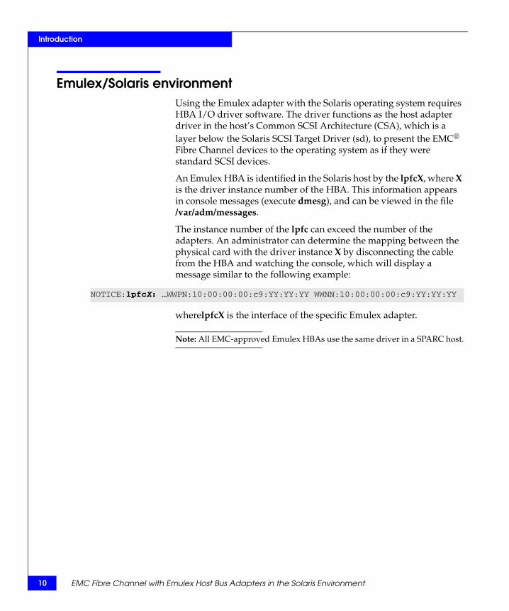
An Emulex HBA is identified in the Solaris host by the lpfcX, where X is the driver instance number of the HBA. This information appears in console messages (execute dmesg), and can be viewed in the file /var/adm/messages.
The instance number of the lpfc can exceed the number of the adapters. An administrator can determine the mapping between the physical card with the driver instance X by disconnecting the cable from the HBA and watching the console, which will display a message similar to the following example:
wherelpfcX is the interface of the specific Emulex adapter.
Note: All EMC-approved Emulex HBAs use the same driver in a SPARC host.
NOTICE:lpfcX: …WWPN:10:00:00:00:c9:YY:YY:YY WWNN:10:00:00:00:c9:YY:YY:YY
EMC Fibre Channel with Emulex Host Bus Adapters in the Solaris Environment

Introduction
Planning zoning in a fabric environmentBefore setting up the hardware in a fabric switch configuration with Symmetrix®, you should plan an effective zone map. Check the switch manufacturer’s user documentation for help on defining zones.
Planning zoning in a fabric environment 11

12
Introduction
EMC Fibre Channel with Emulex Host Bus Adapters in the Solaris Environment
2Invisible Body Tag
This chapter describes the procedures for installing and configuring the Emulex HBA and driver.
◆ Installing the hardware ..................................................................... 14◆ Installing the HBA I/O driver ......................................................... 15◆ Incorporating EMC Fibre Channel .................................................. 27◆ Partitioning and labeling new devices............................................ 43◆ Updating the HBA firmware............................................................ 44◆ Updating the HBA FCode ................................................................ 45◆ Creating a single-HBA zone in a CLARiiON environment ......... 47◆ Replacing HBAs connected to shared CLARiiON systems ......... 49◆ Optimizing the HBA driver in a CLARiiON environment.......... 50◆ Symmetrix/Fabric case study .......................................................... 53
Installing andConfiguring the HBA
and Driver
Installing and Configuring the HBA and Driver 13
14
Installing and Configuring the HBA and Driver
Installing the hardwareThis section describes the procedure for configuring and installing the HBA. Also included are procedures for installing a GBIC and connecting the cables in a CLARiiON® environment.
Installing the HBA
Note: For CLARiiON environments, review your server documentation for slot recommendations that meet or exceed the HBA capabilities: 64-bit, 33 MHz.
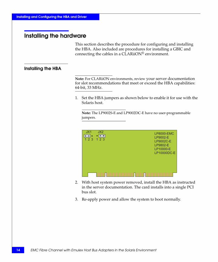
1. Set the HBA jumpers as shown below to enable it for use with the Solaris host.
Note: The LP9002S-E and LP9002DC-E have no user-programmable jumpers.
2. With host system power removed, install the HBA as instructed in the server documentation. The card installs into a single PCI bus slot.
3. Re-apply power and allow the system to boot normally.
321321
JX1 JX2LP8000-EMC
LP9002-E
LP9002C-E
LP9802-E
LP10000-E
LP10000DC-E
EMC Fibre Channel with Emulex Host Bus Adapters in the Solaris Environment
Installing and Configuring the HBA and Driver
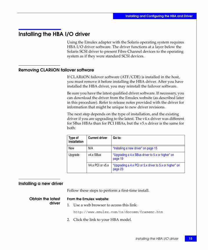
Installing the HBA I/O driverUsing the Emulex adapter with the Solaris operating system requires HBA I/O driver software. The driver functions at a layer below the Solaris SCSI driver to present Fibre Channel devices to the operating system as if they were standard SCSI devices.
Removing CLARiiON failover software
If CLARiiON failover software (ATF/CDE) is installed in the host, you must remove it before installing the HBA driver. After you have installed the HBA driver, you may reinstall the failover software.
Be sure you have the latest qualified driver software. If necessary, you can download the driver from the Emulex website (as described later in this procedure). Refer to release notes provided with the driver for information that might be unique to new driver revisions.
The next step depends on the type of installation, and the existing driver if you are upgrading to the latest. The v4.x driver was different for SBus HBAs than for PCI HBAs, but the v5.x driver is the same for both:
Installing a new driver
Follow these steps to perform a first-time install.
Obtain the latestdriver
From the Emulex website:
1. Use a web browser to access this link:
http://www.emulex.com/ts/docoem/framemc.htm
2. Click the link to your HBA model.
Type of installation
Current driver Go to:
New N/A “Installing a new driver” on page 15
Upgrade v4.x SBus “Upgrading a 4.x SBus driver to 5.x or higher” on page 19
V4.x PCI or v5.x “Upgrading a 4.x PCI or 5.x driver to 5.x or higher” on page 23
Installing the HBA I/O driver 15

16
Installing and Configuring the HBA and Driver
3. Under Drivers for Solaris, find the correct driver version (as shown in the EMC Support Matrix) for your HBA, and click Installation and Configuration in the Online Manuals column.
4. Proceed to “Install the driver” on page 16.
From the Emulex CD-ROM:
1. Insert the Emulex CD-ROM.
2. Make an /emulex directory:
mkdir /emulex
3. Change to the driver directory:
cd /cdrom/emulex/solaris_sparc/driver
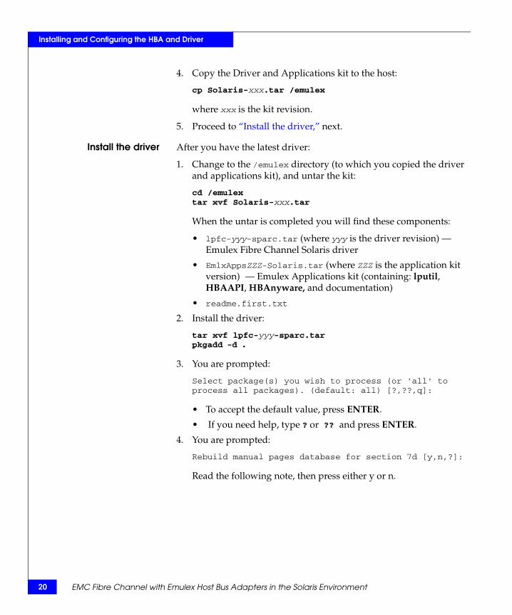
4. Copy the Driver and Applications kit to the host:
cp Solaris-xxx.tar /emulex
where xxx is the kit revision.
5. Proceed to “Install the driver”.
Install the driver After you have the latest driver:
1. Change to the /emulex directory (to which you copied the Driver and Applications kit) and untar the kit:
cd /emulextar xvf Solaris-xxx.tar
When the untar is completed you will find these components:
• lpfc-yyy-sparc.tar (where yyy is the driver revision) — Emulex Fibre Channel Solaris driver
• EmlxAppsZZZ-Solaris.tar (where ZZZ is the application kit version) — Emulex Applications Kit (containing: lputil, HBAAPI, HBAnyware, and documentation)
• readme.first.txt _
2. Install the driver:
tar xvf lpfc-yyy-sparc.tarpkgadd -d .
EMC Fibre Channel with Emulex Host Bus Adapters in the Solaris Environment
Installing and Configuring the HBA and Driver
3. You are prompted:
Select package(s) you wish to process (or 'all' to process all packages). (default: all) [?,??,q]:
• To accept the default value, press ENTER
• If you need help, type ? or ?? and press ENTER.
4. You are prompted:
Rebuild manual pages database for section 7d [y,n,?]Read the following note, then press either Y or N.
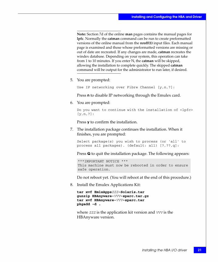
Note: Section 7d of the online man pages contains the manual pages for lpfc. Normally the catman command can be run to create preformatted versions of the online manual from the nroff(1) input files. Each manual page is examined and those whose preformatted versions are missing or out of date are recreated. If any changes are made, catman recreates the windex database. Depending on your system, this operation can take from 1 to 10 minutes. If you enter N, the catman will be skipped, allowing the installation to complete quickly. The skipped catman command will be output for the administrator to run later, if desired.
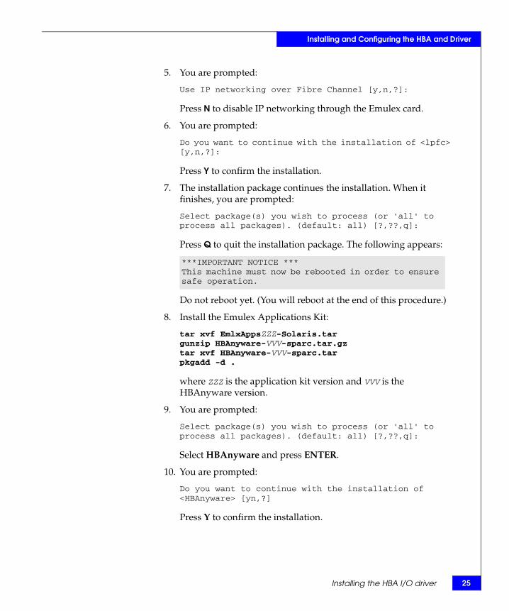
5. You are prompted:
Use IP networking over Fibre Channel [y,n,?]:
Press N to disable IP networking through the Emulex card.
6. You are prompted:
Do you want to continue with the installation of <lpfc> [y,n,?]:
Press Y to confirm the installation.
7. The installation package continues the installation. When it finishes, you are prompted:
Select package(s) you wish to process (or 'all' to process all packages). (default: all) [?,??,q]:
Press Q to quit the installation package. The following appears:
Do not reboot yet. (You will reboot at the end of this procedure.)
***IMPORTANT NOTICE ***This machine must now be rebooted in order to ensure safe operation.
Installing the HBA I/O driver 17
18
Installing and Configuring the HBA and Driver
8. Install the Emulex Applications Kit:
tar xvf EmlxAppsZZZ-Solaris.tarunpack_appsgunzip HBAnyware-VVV-sparc.tar.gztar xvf HBAnyware-VVV-sparc.tarpkgadd -d .
where ZZZ is the application kit version and VVV is the HBAnyware version.
Note: Run unpack_apps script to obtain correct package version if you are installing the Emulex application kit version 300a76 (EmlxApps300a76-Solaris.tar) or higher.
HBAnyware must be updated to the version that is packaged in the driver bundle to avoid incompatibility between the new driver and the old lputil utility.
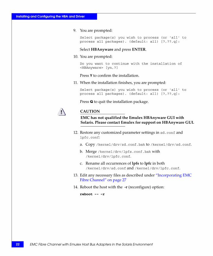
9. You are prompted:
Select package(s) you wish to process (or 'all' to process all packages). (default: all) [?,??,q]:
Select HBAnyware and press ENTER.
10. You are prompted:
Do you want to continue with the installation of <HBAnyware> [yn,?]
Press y to confirm the installation.
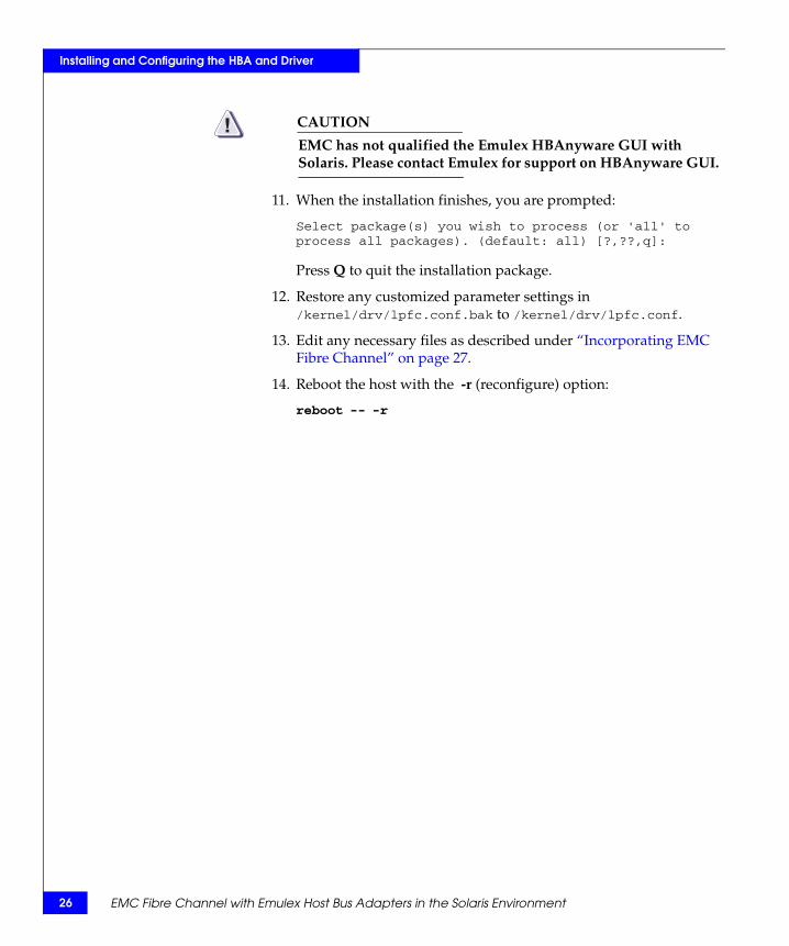
11. When the installation finishes, you are prompted:
Select package(s) you wish to process (or 'all' to process all packages). (default: all) [?,??,q]:
Press Q to quit the installation package.
CAUTION!EMC has not qualified the Emulex HBAnyware GUI with Solaris. Please contact Emulex for support on HBAnyware GUI.
12. Edit any necessary files as described under “Incorporating EMC Fibre Channel” on page 27.
13. Reboot the host with the -r (reconfigure) option:
reboot -- -r
EMC Fibre Channel with Emulex Host Bus Adapters in the Solaris Environment
Installing and Configuring the HBA and Driver
Upgrading a 4.x SBus driver to 5.x or higherIf you are upgrading from a v4.x SBus driver to any v5.x or higher driver, follow these steps.
Back up files andremove the old driver
1. Back up the configuration file:
cp /kernel/drv/lpfs.conf /kernel/drv/lpfs.conf.bak
2. Back up the sd.conf file:
cp /kernel/drv/sd.conf /kernel/drv/sd.conf.bak
3. Back up the path_to_inst file:
cp /etc/path_to_inst /etc/path_to_inst.bak
4. Remove the 4.x driver:
pkgrm lpfs
5. Restore the path_to_inst file:
cp /etc/path_to_inst.bak /etc/path_to_inst
6. Proceed to “Obtain the latest driver,” next.
Obtain the latestdriver
From the Emulex website:
1. Use a web browser to access this link:
http://www.emulex.com/ts/docoem/framemc.htm
2. Click the link to your HBA model.
3. Under Drivers for Solaris, find the correct driver version (as shown in the EMC Support Matrix) for your HBA, and click Installation and Configuration in the Online Manuals column.
4. Proceed to “Install the driver” on page 20.
From the Emulex CD-ROM:
1. Insert the Emulex CD-ROM.
2. Make an /emulex directory:
mkdir /emulex
3. Change to the driver directory:
cd /cdrom/emulex/solaris_sparc/driver
Installing the HBA I/O driver 19
20
Installing and Configuring the HBA and Driver
4. Copy the Driver and Applications kit to the host:
cp Solaris-xxx.tar /emulex
where xxx is the kit revision.
5. Proceed to “Install the driver,” next.
Install the driver After you have the latest driver:
1. Change to the /emulex directory (to which you copied the driver and applications kit), and untar the kit:
cd /emulextar xvf Solaris-xxx.tar
When the untar is completed you will find these components:
• lpfc-yyy-sparc.tar (where yyy is the driver revision) — Emulex Fibre Channel Solaris driver
• EmlxAppsZZZ-Solaris.tar (where ZZZ is the application kit version) — Emulex Applications kit (containing: lputil, HBAAPI, HBAnyware, and documentation)
• readme.first.txt _
2. Install the driver:
tar xvf lpfc-yyy-sparc.tarpkgadd -d .
3. You are prompted:
Select package(s) you wish to process (or 'all' to process all packages). (default: all) [?,??,q]:
• To accept the default value, press ENTER.
• If you need help, type ? or ?? and press ENTER.
4. You are prompted:
Rebuild manual pages database for section 7d [y,n,?]:
Read the following note, then press either y or n.
EMC Fibre Channel with Emulex Host Bus Adapters in the Solaris Environment
Installing and Configuring the HBA and Driver
Note: Section 7d of the online man pages contains the manual pages for lpfc. Normally the catman command can be run to create preformatted versions of the online manual from the nroff(1) input files. Each manual page is examined and those whose preformatted versions are missing or out of date are recreated. If any changes are made, catman recreates the windex database. Depending on your system, this operation can take from 1 to 10 minutes. If you enter N, the catman will be skipped, allowing the installation to complete quickly. The skipped catman command will be output for the administrator to run later, if desired.
5. You are prompted:
Use IP networking over Fibre Channel [y,n,?]:
Press n to disable IP networking through the Emulex card.
6. You are prompted:
Do you want to continue with the installation of <lpfc> [y,n,?]:
Press y to confirm the installation.
7. The installation package continues the installation. When it finishes, you are prompted:
Select package(s) you wish to process (or 'all' to process all packages). (default: all) [?,??,q]:
Press Q to quit the installation package. The following appears:
Do not reboot yet. (You will reboot at the end of this procedure.)
8. Install the Emulex Applications Kit:
tar xvf EmlxAppsZZZ-Solaris.targunzip HBAnyware-VVV-sparc.tar.gztar xvf HBAnyware-VVV-sparc.tarpkgadd -d .
where ZZZ is the application kit version and VVV is the HBAnyware version.
***IMPORTANT NOTICE ***This machine must now be rebooted in order to ensure safe operation.
Installing the HBA I/O driver 21
22
Installing and Configuring the HBA and Driver
9. You are prompted:
Select package(s) you wish to process (or 'all' to process all packages). (default: all) [?,??,q]:
Select HBAnyware and press ENTER.
10. You are prompted:
Do you want to continue with the installation of <HBAnyware> [yn,?]
Press Y to confirm the installation.
11. When the installation finishes, you are prompted:
Select package(s) you wish to process (or 'all' to process all packages). (default: all) [?,??,q]:
Press Q to quit the installation package.
CAUTION!EMC has not qualified the Emulex HBAnyware GUI with Solaris. Please contact Emulex for support on HBAnyware GUI.
12. Restore any customized parameter settings in sd.conf and lpfc.conf:
a. Copy /kernel/drv/sd.conf.bak to /kernel/drv/sd.conf.
b. Merge /kernel/drv/lpfs.conf.bak with /kernel/drv/lpfc.conf.
c. Rename all occurrences of lpfs to lpfc in both /kernel/drv/sd.conf and /kernel/drv/lpfc.conf.
13. Edit any necessary files as described under “Incorporating EMC Fibre Channel” on page 27
14. Reboot the host with the -r (reconfigure) option:
reboot -- -r
EMC Fibre Channel with Emulex Host Bus Adapters in the Solaris Environment
Installing and Configuring the HBA and Driver
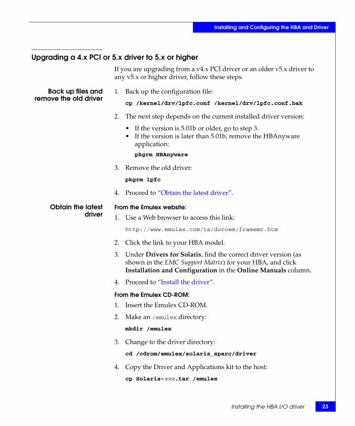
Upgrading a 4.x PCI or 5.x driver to 5.x or higherIf you are upgrading from a v4.x PCI driver or an older v5.x driver to any v5.x or higher driver, follow these steps.
Back up files andremove the old driver
1. Back up the configuration file:
cp /kernel/drv/lpfc.conf /kernel/drv/lpfc.conf.bak
2. The next step depends on the current installed driver version:
• If the version is 5.01b or older, go to step 3.• If the version is later than 5.01b, remove the HBAnyware
application:
pkgrm HBAnyware
3. Remove the old driver:
pkgrm lpfc
4. Proceed to “Obtain the latest driver”.
Obtain the latestdriver
From the Emulex website:
1. Use a Web browser to access this link:
http://www.emulex.com/ts/docoem/framemc.htm
2. Click the link to your HBA model.
3. Under Drivers for Solaris, find the correct driver version (as shown in the EMC Support Matrix) for your HBA, and click Installation and Configuration in the Online Manuals column.
4. Proceed to “Install the driver”.
From the Emulex CD-ROM:
1. Insert the Emulex CD-ROM.
2. Make an /emulex directory:
mkdir /emulex
3. Change to the driver directory:
cd /cdrom/emulex/solaris_sparc/driver
4. Copy the Driver and Applications kit to the host:
cp Solaris-xxx.tar /emulex
Installing the HBA I/O driver 23

24
Installing and Configuring the HBA and Driver
where xxx is the kit revision.
5. Proceed to “Install the driver” on page 24.
Install the driver After you have the latest driver:
1. Change to the /emulex directory (to which you copied the Driver and Applications kit) and untar the kit:
cd /emulextar xvf Solaris-xxx.tar
When the untar is completed you will find these components:
• lpfc-yyy-sparc.tar (where yyy is the driver revision) — Emulex Fibre Channel Solaris driver
• EmlxAppsZZZ-Solaris.tar (where ZZZ is the application kit version) — Emulex Applications kit (containing: lputil, HBAAPI, HBAnyware, and documentation)
• readme.first.txt _
2. Install the driver:
tar xvf lpfc-yyy-sparc.tarpkgadd -d .
3. You are prompted:
Select package(s) you wish to process (or 'all' to process all packages). (default: all) [?,??,q]:
• To accept the default value, press ENTER
• If you need help, type ? or ?? and press ENTER.
4. You are prompted:
Rebuild manual pages database for section 7d [y,n,?]:
Read the following note, then press either Y or N.
Note: Section 7d of the online man pages contains the manual pages for lpfc. Normally the catman command can be run to create preformatted versions of the online manual from the nroff(1) input files. Each manual page is examined and those whose preformatted versions are missing or out of date are recreated. If any changes are made, catman recreates the windex database. Depending on your system, this operation can take from 1 to 10 minutes. If you enter N, the catman will be skipped, allowing the installation to complete quickly. The skipped catman command will be output for the administrator to run later, if desired.
EMC Fibre Channel with Emulex Host Bus Adapters in the Solaris Environment
Installing and Configuring the HBA and Driver
5. You are prompted:
Use IP networking over Fibre Channel [y,n,?]:
Press N to disable IP networking through the Emulex card.
6. You are prompted:
Do you want to continue with the installation of <lpfc> [y,n,?]:
Press Y to confirm the installation.
7. The installation package continues the installation. When it finishes, you are prompted:
Select package(s) you wish to process (or 'all' to process all packages). (default: all) [?,??,q]:
Press Q to quit the installation package. The following appears:
Do not reboot yet. (You will reboot at the end of this procedure.)
8. Install the Emulex Applications Kit:
tar xvf EmlxAppsZZZ-Solaris.targunzip HBAnyware-VVV-sparc.tar.gztar xvf HBAnyware-VVV-sparc.tarpkgadd -d .
where ZZZ is the application kit version and VVV is the HBAnyware version.
9. You are prompted:
Select package(s) you wish to process (or 'all' to process all packages). (default: all) [?,??,q]:
Select HBAnyware and press ENTER.
10. You are prompted:
Do you want to continue with the installation of <HBAnyware> [yn,?]
Press Y to confirm the installation.
***IMPORTANT NOTICE ***This machine must now be rebooted in order to ensure safe operation.
Installing the HBA I/O driver 25
26
Installing and Configuring the HBA and Driver
CAUTION!EMC has not qualified the Emulex HBAnyware GUI with Solaris. Please contact Emulex for support on HBAnyware GUI.
11. When the installation finishes, you are prompted:
Select package(s) you wish to process (or 'all' to process all packages). (default: all) [?,??,q]:
Press Q to quit the installation package.
12. Restore any customized parameter settings in /kernel/drv/lpfc.conf.bak to /kernel/drv/lpfc.conf.
13. Edit any necessary files as described under “Incorporating EMC Fibre Channel” on page 27.
14. Reboot the host with the -r (reconfigure) option:
reboot -- -r
EMC Fibre Channel with Emulex Host Bus Adapters in the Solaris Environment
Installing and Configuring the HBA and Driver
Incorporating EMC Fibre ChannelOnce the EMC storage array has devices assigned with device addresses, the host can see all the target EMC devices assigned to that interface. Devices are presented to the host in the same manner as devices accessed through a standard SCSI interface.
To ensure smooth integration and maximum performance from the host and the EMC storage array, you must edit these files (as described in detail later):
◆ Emulex driver configuration file lpfc.conf — Refer to “Editing lpfc.conf” on page 29.
◆ Host sd driver configuration file sd.conf — Refer to “Adding Target IDs and LUNS” on page 39.
◆ System specification file etc/system — Refer to “Editing /etc/system” on page 41.
After editing the files, type reboot -- -r and press ENTER. This reboots the host with the -r (reconfigure) option, which rebuilds the kernel and implements the changes.
Fabric environment specifics
The Emulex HBA and the EMC storage array act as separate nodes that participate in the same switched fabric environment. Therefore, prior to the setup of the Emulex HBA driver file (lpfc.conf), the administrator must enable the storage array to participate in the fabric. The administrator must also configure the switch to enable the EMC storage array and the hosts to "see" each other. (Refer to the user manual for the switch.)
Persistent bindingimplementation
Emulex persistent binding is implemented through both /kernel/drv/lpfc.conf and /kernel/drv/sd.conf. The matching between the EMC storage array port, host adapter instance, and target ID occurs inside lpfc.conf. On the other hand, the matching between the target ID, host adapter instance, and LUN occurs inside sd.conf. All of these configurations assume that the settings for the persistent binding in lpfc.conf is enabled and the EMC storage array is being configured in the physical addressing mode (on Symmetrix, V-bit is disabled).
Incorporating EMC Fibre Channel 27
28
Installing and Configuring the HBA and Driver
CAUTION!The modification of the default entries (target 0 to target 15) inside /kernel/drv/sd.conf might cause the host machine fail to boot properly because the Solaris operating system uses targets 0 to 15 as the reference or the bind to the internal boot drive.
Inside lpfc.conf, the EMC storage array port (target) is mapped against a target number that is defined as one of the entries inside sd.conf. The mapping is done by defining the lpfcXtY properties, where the X corresponds to the driver instance number, and the Y is the target ID. Note that this target ID does not correspond to the loop ID defined by the Fibre Channel AL_PA (as in an arbitrated loop configuration); however, it is a logical definition of the relationship between the EMC storage array port ID and the device address.
Although the current Emulex HBA driver enables three different binding methods (World Wide Node Name, World Wide Port Name, and DID), the recommended setup uses the World Wide Port Name (WWPN).
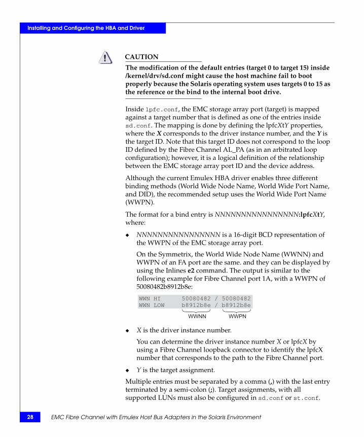
The format for a bind entry is NNNNNNNNNNNNNNNN:lpfcXtY, where:
◆ NNNNNNNNNNNNNNNN is a 16-digit BCD representation of the WWPN of the EMC storage array port.
On the Symmetrix, the World Wide Node Name (WWNN) and WWPN of an FA port are the same. and they can be displayed by using the Inlines e2 command. The output is similar to the following example for Fibre Channel port 1A, with a WWPN of 50080482b8912b8e:
◆ X is the driver instance number.
You can determine the driver instance number X or lpfcX by using a Fibre Channel loopback connector to identify the lpfcX number that corresponds to the path to the Fibre Channel port.
◆ Y is the target assignment.
Multiple entries must be separated by a comma (,) with the last entry terminated by a semi-colon (;). Target assignments, with all supported LUNs must also be configured in sd.conf or st.conf.
WWN HI 50080482 / 50080482WWN LOW b8912b8e / b8912b8e
WWNN WWPN
EMC Fibre Channel with Emulex Host Bus Adapters in the Solaris Environment
Installing and Configuring the HBA and Driver
Sample entry:
Using lputil to set up persistent binding
The Emulex driver comes with a utility called lputil to set up persistent binding (among other functions). To set up binding, follow these steps, repeating them for each adapter:
1. Type the following and press ENTER:
/usr/sbin/lpfc/lputil
This displays a menu.
2. Select 5. - Persistent Bindings.
3. Select 5. - Bind Automapped Targets.
4. Select an adapter, 0–n, where n is the number of adapters installed in your system.
5. For Bind all auto-mapped targets? (Y/N) = >, select Y (yes).
6. Select 2. - Bind by port name.
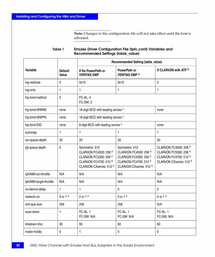
Editing lpfc.confConfiguration file lpfc.conf is created automatically by pkgadd. The file contains important information about how the driver should behave. If necessary, edit the file using the recommended setting (table_value) for each variable, as shown in Table 1 on page 30. Descriptions of the variables follow the table.
fcp-bind-WWPN="50080482b8912b8e:lpfc0t0",
"50080482b8912b9e:lpfc0t1";
Incorporating EMC Fibre Channel 29
30
Installing and Configuring the HBA and Driver
Note: Changes to the configuration file will not take effect until the host is rebooted.
Table 1 Emulex Driver Configuration File (lpfc.conf) Variables and Recommended Settings (table_value)
Variable Default Value
Recommended Setting (table_value)
If No PowerPath or VERITAS DMP
PowerPath or VERITAS DMP a
If CLARiiON with ATF b
log-verbose 0 0x10 0x10 0
log-only 1 1 1 1
fcp-bind-method 2 FC-AL: 4FC-SW: 2
fcp-bind-WWNN none 16-digit BCD with leading zeroes c none
fcp-bind-WWPN none 16-digit BCD with leading zeroes c
fcp-bind-DID none 6-digit BCD with leading zeroes c none
automap 1 1 1 1
lun-queue-depth 30 20 20 20
tgt-queue-depth 0 Symmetrix: 512CLARIiON FC4500: 256 d
CLARiiON FC5300: 256 d
CLARiiON FC4700: 512 d
CLARiiON CXseries: 512 d
Symmetrix: 512CLARIiON FC4500: 256 d
CLARiiON FC5300: 256 d
CLARiiON FC4700: 512 d
CLARiiON CXseries: 512 d
CLARIiON FC4500: 256 d
CLARiiON FC5300: 256 d
CLARiiON FC4700: 512 d
CLARiiON CXseries: 512 d
lpfcNtM-lun-throttle N/A N/A N/A N/A
lpfcNtM-target-throttle N/A N/A N/A N/A
no-device-delay 1 1 0 0
network-on 0 or 1 e 0 or 1 e 0 or 1 e 0 or 1 e
xmt-que-size 256 256 256 N/A
scan-down 1 FC-AL: 1FC-SW: N/A
FC-AL: 1FC-SW: N/A
FC-AL: 1FC-SW: N/A
linkdown-tmo 30 60 60 60
nodev-holdio 0 1 0 0
EMC Fibre Channel with Emulex Host Bus Adapters in the Solaris Environment
Installing and Configuring the HBA and Driver
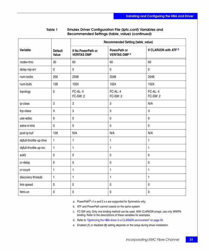
a. PowerPath® v1.x and 2.x.x are supported for Symmetrix only.
b. ATF and PowerPath cannot coexist on the same system.
c. FC-SW only. Only one binding method can be used. With CLARiiON arrays, use only WWPN binding. Refer to the descriptions of these variables for examples.
d. Refer to “Optimizing the HBA driver in a CLARiiON environment” on page 50.
e. Enabled (1) or disabled (0) setting depends on the setup during driver installation.
nodev-tmo 30 60 60 60
delay-rsp-err 0 0 0 0
num-iocbs 256 2048 2048 2048
num-bufs 128 1024 1024 1024
topology 0 FC-AL: 4FC-SW: 2
FC-AL: 4FC-SW: 2
FC-AL: 4FC-SW: 2
ip-class 3 3 3 N/A
fcp-class 3 3 3 3
use-adisc 0 0 0 0
extra-io-tmo 0 0 0 0
post-ip-buf 128 N/A N/A N/A
dqfull-throttle-up-time 1 1 1 1
dqfull-throttle-up-inc 1 1 1 1
ack0 0 0 0 0
cr-delay 0 0 0 0
cr-count 1 1 1 1
discovery-threads 1 1 1 1
link-speed 0 0 0 0
fdmi-on 0 0 0 0
Table 1 Emulex Driver Configuration File (lpfc.conf) Variables and Recommended Settings (table_value) (continued)
Variable Default Value
Recommended Setting (table_value)
If No PowerPath or VERITAS DMP
PowerPath or VERITAS DMP a
If CLARiiON with ATF b
Incorporating EMC Fibre Channel 31
32
Installing and Configuring the HBA and Driver
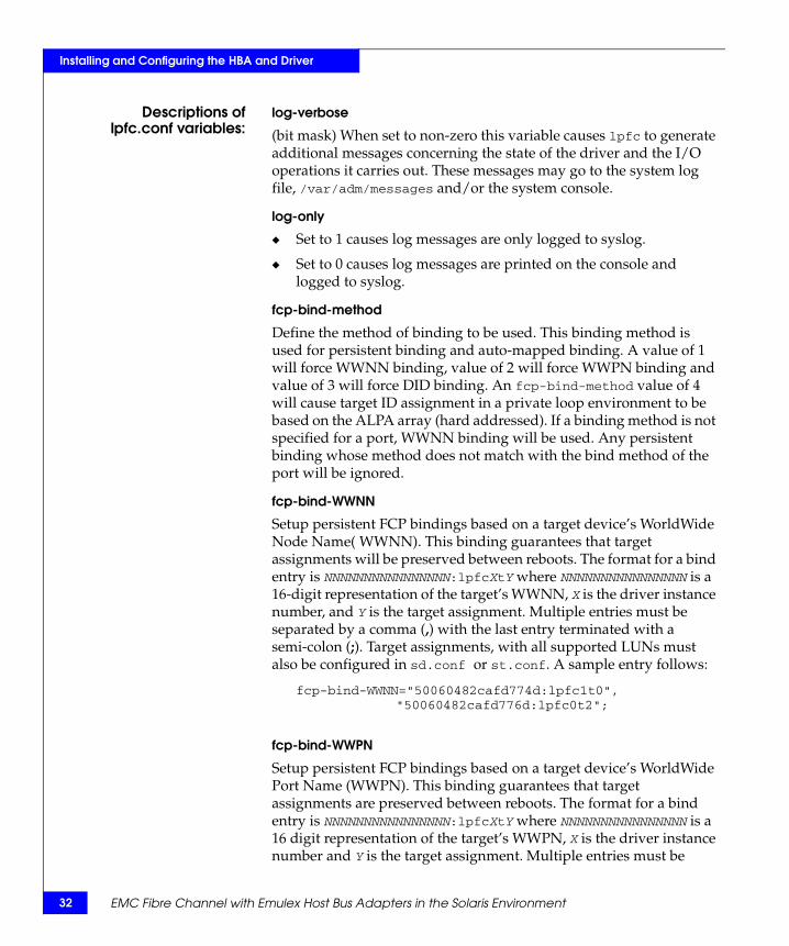
Descriptions oflpfc.conf variables:
log-verbose
(bit mask) When set to non-zero this variable causes lpfc to generate additional messages concerning the state of the driver and the I/O operations it carries out. These messages may go to the system log file, /var/adm/messages and/or the system console.
log-only
◆ Set to 1 causes log messages are only logged to syslog.
◆ Set to 0 causes log messages are printed on the console and logged to syslog.
fcp-bind-method
Define the method of binding to be used. This binding method is used for persistent binding and auto-mapped binding. A value of 1 will force WWNN binding, value of 2 will force WWPN binding and value of 3 will force DID binding. An fcp-bind-method value of 4 will cause target ID assignment in a private loop environment to be based on the ALPA array (hard addressed). If a binding method is not specified for a port, WWNN binding will be used. Any persistent binding whose method does not match with the bind method of the port will be ignored.
fcp-bind-WWNN
Setup persistent FCP bindings based on a target device’s WorldWide Node Name( WWNN). This binding guarantees that target assignments will be preserved between reboots. The format for a bind entry is NNNNNNNNNNNNNNNN:lpfcXtY where NNNNNNNNNNNNNNNN is a 16-digit representation of the target’s WWNN, X is the driver instance number, and Y is the target assignment. Multiple entries must be separated by a comma (,) with the last entry terminated with a semi-colon (;). Target assignments, with all supported LUNs must also be configured in sd.conf or st.conf. A sample entry follows:
fcp-bind-WWNN="50060482cafd774d:lpfc1t0", "50060482cafd776d:lpfc0t2";
fcp-bind-WWPN
Setup persistent FCP bindings based on a target device’s WorldWide Port Name (WWPN). This binding guarantees that target assignments are preserved between reboots. The format for a bind entry is NNNNNNNNNNNNNNNN:lpfcXtY where NNNNNNNNNNNNNNNN is a 16 digit representation of the target’s WWPN, X is the driver instance number and Y is the target assignment. Multiple entries must be
EMC Fibre Channel with Emulex Host Bus Adapters in the Solaris Environment
Installing and Configuring the HBA and Driver
separated by a comma (,) with the last entry terminated with a semi-colon (;). Target assignments, with all supported LUNs must also be configured in sd.conf or st.conf. A sample entry follows:
fcp-bind-WWPN="50060482cccd7744:lpfc1t0";
fcp-bind-DID
Setup persistent FCP bindings based on a target device’s Port ID. This binding guarantees that target assignments are preserved between reboots. The format for a bind entry is NNNNNN:lpfcXtY where NNNNNN is a 6 digit representation of the targets Port ID, X is the driver instance number and Y is the target assignment. Multiple entries must be separated by a comma (,) with the last entry terminated with a semi-colon (;). Target assignments, with all supported LUNs must also be configured in sd.conf or st.conf. A sample entry follows:
fcp-bind-DID="0000ef:lpfc0t0";
automap
If automap is 1, SCSI IDs for all FCP nodes without persistent bindings are automatically generated based on the bind method of the corresponding HBA port. If FCP devices are added to or removed from the Fibre Channel network when the system is down, there is no guarantee that these SCSI IDs will remain the same when the system is booted again. If automap is 0, only devices with persistent bindings are recognized by the system.
lun-queue-depth
The driver uses this value as the default limit for the number of simultaneous commands to issue to a single logical unit on a single target on the loop. A single logical unit is never sent more commands than allowed by lun-queue-depth; however, less may be sent when sd-max-throttle or tgt-queue-depth is reached for the entire target.
tgt-queue-depth
The driver uses this value as the default limit for the number of simultaneous commands to issue to a single target on the loop. A value of 0 causes no target throttling to occur. A single target will never be sent more commands than allowed by tgt-queue-depth; however, less may be sent when sd-max-throttle is reached for the entire target.
Incorporating EMC Fibre Channel 33
34
Installing and Configuring the HBA and Driver
lpfcNtM-lun-throttle
Define the maximum number of outstanding commands to permit for any logical unit on a specific target. This value overrides lun-queue-depth.
lpfcNtM-tgt-throttle
Define the maximum number of outstanding commands to permit for any target, including all LUNs on that target. This value overrides tgt-queue-depth.
no-device-delay
This variable (0 to 30 seconds) determines the length of the interval between deciding to fail an I/O because there is no way to communicate with its particular device (for example, due to device failure or device removal) and actually failing the command. A value of zero implies no delay whatsoever. This delay is specified in seconds. A minimum value of 1 (1 second) is recommended when communicating with any Tachyon-based device.
network-on
This variable controls whether lpfc provides IP networking functionality over Fibre Channel. This variable is a Boolean: when zero (0), IP networking is disabled; when one (1), IP networking is enabled.
xmt-que-size
This variable specifies the number of network packets that can be queued or outstanding at any time in the driver. Increase this setting for better IP performance under heavy loading.
scan-down
The two scanning algorithms used to discover a node in a private loop are:
◆ If scan-down is 1, devices on the private loop are scanned starting from ALPA 0x01 through ALPA 0xEF.
◆ If scan-down is 0, devices on the private loop are scanned starting from ALPA 0xEF through ALPA 0x01.
Scan-down values 0 and 1 do not apply if a loop map is obtained.
EMC Fibre Channel with Emulex Host Bus Adapters in the Solaris Environment
Installing and Configuring the HBA and Driver
linkdown-tmo
Determine how long the driver will wait [0 - 255] to begin linkdown processing when the hba link has become inaccessible. Linkdown processing includes failing back commands that have been waiting for the link to come back up. Units are in seconds. linkdown-tmo works in conjuction with nodev-tmo. I/O will fail when either of the two expires.
nodev-holdio
This variable controls if I/O errors are held by the driver if a device on the loop disappears. If set, I/O errors will be held until the device returns back to the loop (potentially indefinitely). The upper sd layer may retry the command once the error is returned.
nodev-tmo
This variable controls how long I/O errors are held by the driver if a device on the loop disappears. If set, I/O errors will be held for the specified number of seconds. The upper sd layer may retry the command once the error is returned.
delay-rsp-err
The driver will delay FCP RSP errors being returned to the upper SCSI layer based on the no-device-delay configuration parameter.
num-iocbs
This variable indicates the number of Input/Output control block (IOCB) buffers to allocate. IOCBs are internal data structures used to send and receive I/O requests to and from the LightPulse hardware. Too few IOCBs can temporarily prevent the driver from communicating with the adapter, thus lowering performance. (This condition is not fatal.) If you run heavy IP traffic, you should increase num-iocbs for better performance.
num-bufs
This variable specifies the number of command buffers to allocate. These buffers are used for Fibre Channel Extended Link Services (ELS), and one for each FCP command issued in SLI-2 mode. If you want to queue lots of FCP commands to the adapter, then you should increase num-bufs for better performance. These buffers consume physical memory and are also used by the device driver to process loop initialization and re-discovery activities. Important: The driver must always be configured with at least several dozen ELS command buffers; we recommend at least 128.
Incorporating EMC Fibre Channel 35
36
Installing and Configuring the HBA and Driver
topology
This variable controls the Fibre Channel topology expected by lpfc at boot time. Fibre Channel offers point-to-point, fabric, and arbitrated loop topologies. This variable epath namencodes these topologies as follows:
0 Attempt loop mode, if it fails attempt point-to-point mode ◆ 2 Attempt point-to-point mode only
◆ 4 Attempt loop mode only
◆ 6 Attempt point-to-point mode, if it fails attempt loop mode
To make the adapter operate as an N_Port, select point-to-point mode (used for N_Port to F_Port, and N_Port to N_Port connections). To make the adapter operate in a Fibre Channel loop as an NL_Port, select loop mode (used for private loop and public loop topologies). The driver will reject an attempt to set the topology to a value not in the above list. The auto-topology settings 0 and 6 will not work unless the adapter is using firmware version 3.20 or higher.
ip-class
Fibre Channel is capable of transmitting IP data in Class 2 or Class 3. The lpfc driver defaults to using Class 3 transmission.
fcp-class
The lpfc driver is capable of transmitting FCP data in Class 2 or Class 3. The lpfc driver defaults to using Class 3 transmission.
use-adisc
This variable controls the ELS command used for FCP address authentication during discovery. If set, ADISC is used, otherwise, PLOGI is used.
extra-io-tmo
Extra timeout value, in seconds, to be applied to each FCP command sent. When connecting through a large fabric, certain devices may require a longer timeout value.
post-ip-buf
This variable specifies the number of 4K STREAMS buffers to allocate and post to the fibre channel IP ring. Increase this setting for better IP performance under heavy loading.
EMC Fibre Channel with Emulex Host Bus Adapters in the Solaris Environment
Installing and Configuring the HBA and Driver
dqfull-throttle-up-time and dqful-throttle-up-inc
These parameters cause the lpfc driver to decrement a LUN’s queue depth, if a queue full condition is received from the target. The queue depth will be decremented down to a minimum of 1. The variables dqfull-throttle-up-inc and dqfull-throttle-up-time are used to restore the queue depth back to the original. The dqfull-throttle-up-time parameter defines a time, in seconds, that is used to tell when to increase the current queue depth. If the current queue depth is not equal to the lun-queue-depth, and the driver stop_send_io flag is equal to 0 for that device, increment the current queue depth by dqfull-throttle-up-inc (don't exceed the lun-queue-depth). So, if both parameters are set to 1, then driver increments the current queue depth once per second until it hits the lun-queue-depth. The only other way to restore the queue depth (besides rebooting), back to the original LUN throttle, is by running the command /usr/sbin/lpfc/resetqdepth X. This will restore the LUN throttle of all LUNs for adapter X back to the original value.
ack0
If ack0 is 1, the adapter will try to use ACK0 when running Class 2 traffic to a device. If the device doesn’t support ACK0, then the adapter will use ACK1. If ack0 is 0, only ACK1 will be used when running Class 2 traffic.
cr-delay
This value specifies a count of milliseconds after which an interrupt response generated if cr-count has not been satisfied. This value is set to 0 to disable the Coalesce Response feature as default.
cr-count
This value specifies a count of I/O completions after which an interrupt response is generated. This feature is disabled if cr-delay is set to 0.
discovery-threads
This value specifies the number of threads permissible during device discovery. A value of 1 serializes the discovery process.
link-speed
This causes lpfc to set the adapter link speed to auto-detect (0), 1 gigabit/sec (1) or 2 gigabit/sec (2). This setting only applies to the LightPulse 9002, 9002S, 9802 and 10000 adapters.
Incorporating EMC Fibre Channel 37
38
Installing and Configuring the HBA and Driver
fdmi-on
This parameter controls the fdmi capability of the lpfc driver. If set to 0 (default), fdmi is disabled. A value of 1 enables fdmi without registration of "host name" port attribute, while a value of 2 enables fdmi with registration of "host name" port attribute.
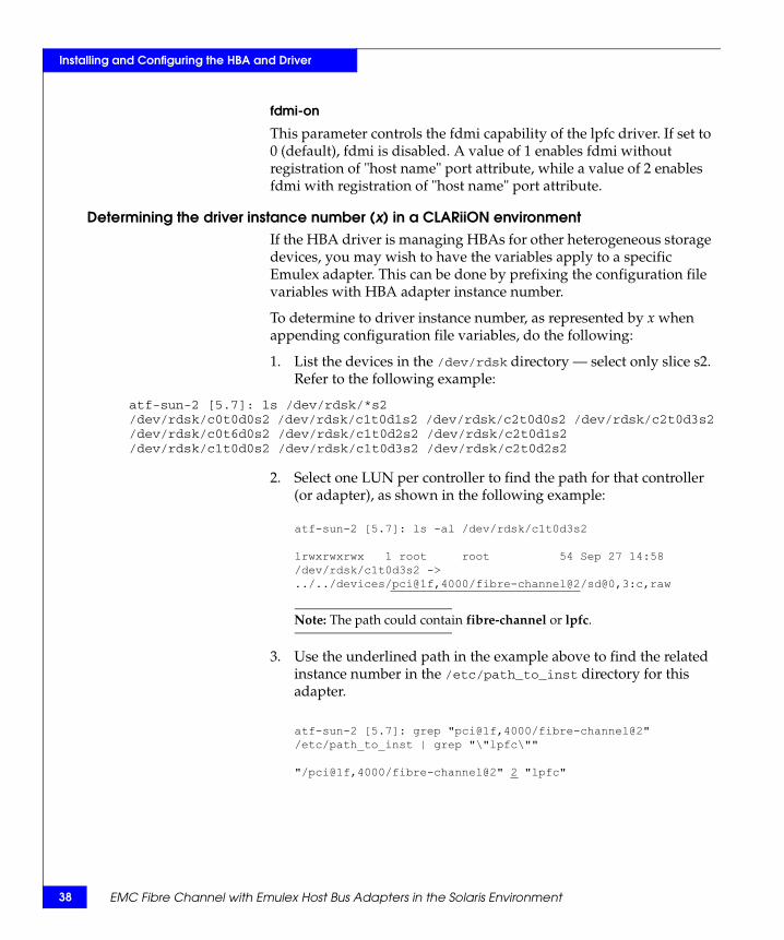
Determining the driver instance number (x) in a CLARiiON environmentIf the HBA driver is managing HBAs for other heterogeneous storage devices, you may wish to have the variables apply to a specific Emulex adapter. This can be done by prefixing the configuration file variables with HBA adapter instance number.
To determine to driver instance number, as represented by x when appending configuration file variables, do the following:
1. List the devices in the /dev/rdsk directory — select only slice s2. Refer to the following example:
atf-sun-2 [5.7]: ls /dev/rdsk/*s2/dev/rdsk/c0t0d0s2 /dev/rdsk/c1t0d1s2 /dev/rdsk/c2t0d0s2 /dev/rdsk/c2t0d3s2/dev/rdsk/c0t6d0s2 /dev/rdsk/c1t0d2s2 /dev/rdsk/c2t0d1s2/dev/rdsk/c1t0d0s2 /dev/rdsk/c1t0d3s2 /dev/rdsk/c2t0d2s2
2. Select one LUN per controller to find the path for that controller (or adapter), as shown in the following example:
Note: The path could contain fibre-channel or lpfc.
3. Use the underlined path in the example above to find the related instance number in the /etc/path_to_inst directory for this adapter.
atf-sun-2 [5.7]: ls -al /dev/rdsk/c1t0d3s2
lrwxrwxrwx 1 root root 54 Sep 27 14:58/dev/rdsk/c1t0d3s2 ->../../devices/pci@1f,4000/fibre-channel@2/sd@0,3:c,raw
atf-sun-2 [5.7]: grep "pci@1f,4000/fibre-channel@2"/etc/path_to_inst | grep "\"lpfc\""
"/pci@1f,4000/fibre-channel@2" 2 "lpfc"
EMC Fibre Channel with Emulex Host Bus Adapters in the Solaris Environment
Installing and Configuring the HBA and Driver
This finds the instance number (underlined in the example above) used in /kernel/drv/lpfc.conf and used to set the variable attributes for that adapter, for example:
lpfc2-topology=2;
Note: On occasion multiple entries exist for a particular path in the path_to_inst file, making it difficult to find the actual instance number being used. However, executing the command prtconf > /tmp/output will show all the adapters configured by the system. Looking through the output for the driver name fibre-channel (or lpfc) will show if the instance number found in step 3 is actually configured on the system.
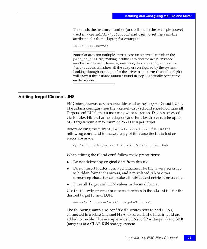
Adding Target IDs and LUNSEMC storage array devices are addressed using Target IDs and LUNs. The Solaris configuration file /kernel/drv/sd.conf should contain all Targets and LUNs that a user may want to access. Devices accessed via Emulex Fibre Channel adapters and Emulex driver can be up to 512 Targets with a maximum of 256 LUNs per target.
Before editing the current /kernel/drv/sd.conf file, use the following command to make a copy of it in case the file is lost or errors are made:
cp /kernel/drv/sd.conf /kernel/drv/sd.conf.bak
When editing the file sd.conf, follow these precautions:
◆ Do not delete any original data from this file.
◆ Do not insert hidden format characters. The file is very sensitive to hidden format characters, and a misplaced tab or other formatting character can make all subsequent entries unreadable.
◆ Enter all Target and LUN values in decimal format.
Use the following format to construct entries in the sd.conf file for the desired target ID and LUN:
name="sd" class="scsi" target=X lun=Y;
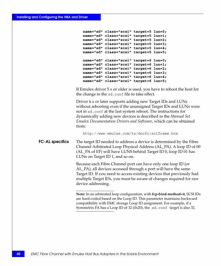
The following sample sd.conf file illustrates how to add LUNs, connected to a Fibre Channel HBA, to sd.conf. The lines in bold are added to the file. This example adds LUNs to SP A (target 5) and SP B (target 6) of a CLARiiON storage system.
Incorporating EMC Fibre Channel 39
40
Installing and Configuring the HBA and Driver
name="sd" class="scsi" target=5 lun=0;name="sd" class="scsi" target=5 lun=1;name="sd" class="scsi" target=5 lun=2;name="sd" class="scsi" target=5 lun=3;name="sd" class="scsi" target=5 lun=4;name="sd" class="scsi" target=5 lun=5;
name="sd" class="scsi" target=6 lun=0;name="sd" class="scsi" target=6 lun=1;name="sd" class="scsi" target=6 lun=2;name="sd" class="scsi" target=6 lun=3;name="sd" class="scsi" target=6 lun=4;name="sd" class="scsi" target=6 lun=5;
If Emulex driver 5.x or older is used, you have to reboot the host for the change in the sd.conf file to take effect.
Driver 6.x or later supports adding new Target IDs and LUNs without rebooting even if the unassigned Target IDs and LUNs were not in sd.conf at the last system reboot. The instructions for dynamically adding new devices is described in the Manual Set Emulex Documentation Drivers and Software, which can be obtained from:
http://www.emulex.com/ts/docfc/solframe.htm
FC-AL specifics The target ID needed to address a device is determined by the Fibre Channel Arbitrated Loop Physical Address (AL_PA). A loop ID of 00 (AL_PA of EF) will have LUNS behind Target ID 0, loop ID 01 has LUNs on Target ID 1, and so on.
Because each Fibre Channel port can have only one loop ID (or AL_PA), all devices accessed through a port will have the same Target ID. If you need to access existing devices that previously had multiple Target IDs, you must be aware of changes required for raw device addressing.
Note: In an arbitrated loop configuration, with fcp-bind-method=4, SCSI IDs are hard-coded based on the Loop ID. This parameter maintains backward compatibility with EMC storage Loop ID assignment. For example, if a Symmetrix FA has a Loop ID of 32 (0x20), the sd.conf target is also 32.
EMC Fibre Channel with Emulex Host Bus Adapters in the Solaris Environment
Installing and Configuring the HBA and Driver
Editing /etc/systemOperation in a Solaris environment requires that some parameters in the file /etc/system must be modified, as described below.
Note: Changes to /etc/system will not take effect until the host is rebooted.
Note: The parameter sd_max_throttle must be modified specifically for Fibre Channel. Other settings apply to both standard SCSI and Fibre Channel.
1. Add this line: set sd:sd_max_throttle=20
A maximum throttle setting of 20 means that each host device instance will have no more than 20 commands outstanding (incomplete IO’s from the standpoint of the operating system) at any given time. The value of 20 was arrived at by testing the incremental gains of increasing queue depth, and it was found that a queue depth of 20 represents a point where negligible incremental performance gains will usually be reached. It does not make sense to additionally offload IO onto the stack, and thereby unnecessarily use up resources throughout the stack, for no performance gain. A balance should be found.
In the case of metadevices (which have more physical devices on the back end and can thus physically process more IO’s in parallel), it may be beneficial to increase the queue depth to 32. It is important to note that in Solaris the sd_max_throttle settings are global, so all devices including non-meta’s will also be affected.
The max throttle setting of 20 is suitable for many environments. However, in some situations this value can be further fine tuned for configuration-specific optimizations. Your local EMC performance expert can assist with fine tuning recommendations, if any.
2. Add a line to set the I/O timeout. This setting prevents the host from issuing warning messages when non-disruptive operations are performed on the EMC storage array:
set sd:sd_io_time = 0x3C
Incorporating EMC Fibre Channel 41
42
Installing and Configuring the HBA and Driver
Target and LUN blockingThe Target and LUN blocking feature is a method where the user can limit the sd driver from probing targets and LUNs on an adapter by adapter basis. Thus, this feature can be used to reduce system bootup time.
Use the following format to construct entries in the sd.conf file to probe a specific adapter (lpfcZ) for the desired Target ID and LUN.
name="sd" parent="lpfc" target=X lun=Y hba="lpfcZ";
This entry will not cancel the effect of any other class="scsi" entries for target=X and lun=Y. If the user wants the sd driver to proble only for target=X and lun=Y on adapter lpfcZ, the class="scsi" entries for target-X and lun=Y must be deleted.
CAUTION!Do not delete the SCSI boot disk Target and LUN entry in the sd.conf file. If you remove it, the system will not boot.
EMC Fibre Channel with Emulex Host Bus Adapters in the Solaris Environment
Installing and Configuring the HBA and Driver
Partitioning and labeling new devicesUse the format command to partition and label new Fibre Channel devices. The devices will appear under /dev/dsk.
To partition and label new devices:
1. At the root prompt, type format and press ENTER.
The host searches for all disks and displays a list, placing all unlabeled disks at the beginning of the list.
2. At the Specify Disk prompt, enter the number of the first EMC drive.
3. The FORMAT MENU appears. At the format prompt, type label and press ENTER.
4. At the Disk not labeled. Label it now? prompt, type Y and press ENTER.
5. Type disk and press ENTER at the prompt to display a list of the disks.
6. Repeat steps 2 through 5 for each EMC disk.
Partitioning and labeling new devices 43
44
Installing and Configuring the HBA and Driver
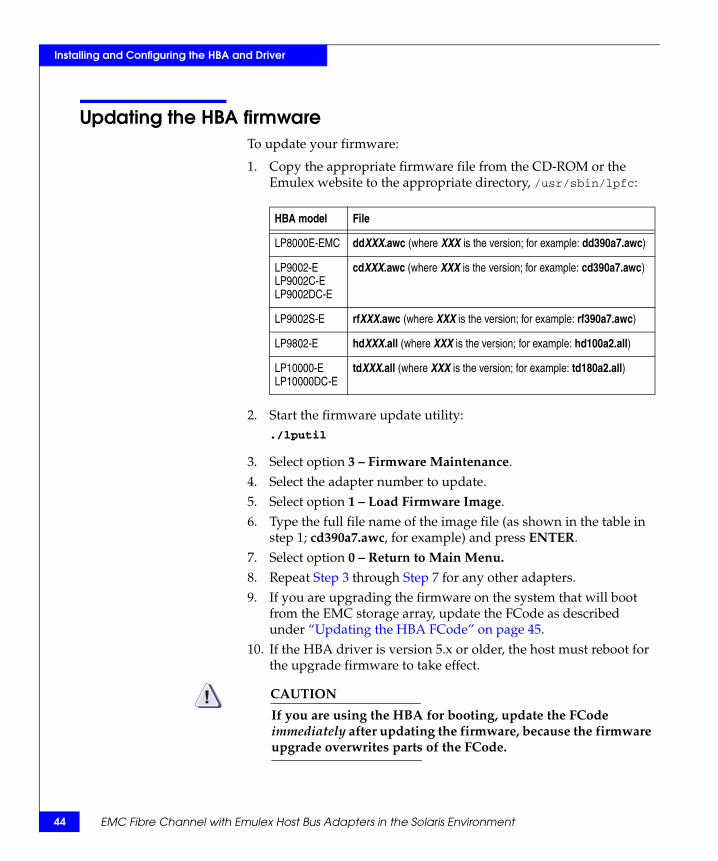
Updating the HBA firmwareTo update your firmware:
1. Copy the appropriate firmware file from the CD-ROM or the Emulex website to the appropriate directory, /usr/sbin/lpfc:
2. Start the firmware update utility:./lputil
3. Select option 3 – Firmware Maintenance.4. Select the adapter number to update.5. Select option 1 – Load Firmware Image.6. Type the full file name of the image file (as shown in the table in
step 1; cd390a7.awc, for example) and press ENTER.7. Select option 0 – Return to Main Menu.
8. Repeat Step 3 through Step 7 for any other adapters.9. If you are upgrading the firmware on the system that will boot
from the EMC storage array, update the FCode as described under “Updating the HBA FCode” on page 45.
10. If the HBA driver is version 5.x or older, the host must reboot for the upgrade firmware to take effect.
CAUTION!If you are using the HBA for booting, update the FCode immediately after updating the firmware, because the firmware upgrade overwrites parts of the FCode.
HBA model File
LP8000E-EMC ddXXX.awc (where XXX is the version; for example: dd390a7.awc)
LP9002-ELP9002C-ELP9002DC-E
cdXXX.awc (where XXX is the version; for example: cd390a7.awc)
LP9002S-E rfXXX.awc (where XXX is the version; for example: rf390a7.awc)
LP9802-E hdXXX.all (where XXX is the version; for example: hd100a2.all)
LP10000-ELP10000DC-E
tdXXX.all (where XXX is the version; for example: td180a2.all)
EMC Fibre Channel with Emulex Host Bus Adapters in the Solaris Environment
Installing and Configuring the HBA and Driver
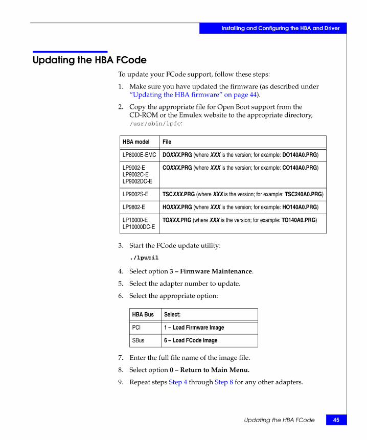
Updating the HBA FCodeTo update your FCode support, follow these steps:
1. Make sure you have updated the firmware (as described under “Updating the HBA firmware” on page 44).
2. Copy the appropriate file for Open Boot support from the CD-ROM or the Emulex website to the appropriate directory, /usr/sbin/lpfc:
3. Start the FCode update utility:
./lputil
4. Select option 3 – Firmware Maintenance.
5. Select the adapter number to update.
6. Select the appropriate option:
7. Enter the full file name of the image file.
8. Select option 0 – Return to Main Menu.
9. Repeat steps Step 4 through Step 8 for any other adapters.
HBA model File
LP8000E-EMC DOXXX.PRG (where XXX is the version; for example: DO140A0.PRG)
LP9002-ELP9002C-ELP9002DC-E
COXXX.PRG (where XXX is the version; for example: CO140A0.PRG)
LP9002S-E TSCXXX.PRG (where XXX is the version; for example: TSC240A0.PRG)
LP9802-E HOXXX.PRG (where XXX is the version; for example: HO140A0.PRG)
LP10000-ELP10000DC-E
TOXXX.PRG (where XXX is the version; for example: TO140A0.PRG)
HBA Bus Select:
PCI 1 – Load Firmware Image
SBus 6 – Load FCode Image
Updating the HBA FCode 45
46
Installing and Configuring the HBA and Driver
10. Type reboot -- -r and press ENTER to reboot the host with the -r (reconfigure) option.
CAUTION!Make sure your storage array device path is /pci/lpfc. If you see that the path is /pci/fibre_channel, you must download the Fcode again and reboot the system with the command reboot -- -rv.
EMC Fibre Channel with Emulex Host Bus Adapters in the Solaris Environment
Installing and Configuring the HBA and Driver
Creating a single-HBA zone in a CLARiiON environment
Note: This section applies only to fabric configurations with CLARiiON storage arrays.
EMC requires single-initiator zoning. This means that each HBA has a separate zone that contains it and the SP with which it communicates. The following zoning configuration rules apply:
◆ Fan-out of 32 initiators registered to each SP port on an FC4700 storage system and 15 hosts to one non-FC4700 storage system.
◆ Fan-in of four storage systems to one host.
How you set up a zone on a switch depends on the type of switches you are using.
◆ DS-8B, DS-16B, DS-16B2, DS-32B2, ED-12000B — Proceed to “Creating a DS-xB or ED-12000B switch zone for each HBA,” next.
◆ DS-16M, DS-16M2, DS-24M2, DS-32M, DS-32M2, ED-64, ED-140M, or ED-1032 — Refer to the documentation for the switch.
Creating a DS-xB or ED-12000B switch zone for each HBA
You use the Web Tools to zone a DS-8B, DS-16B, DS-16B2, DS-32B2, or ED-12000B. If you are unfamiliar with Web Tools or with how zoning operates on these switches, refer to the Web Tools user guides, zoning reference manuals, and Quickloop reference manuals, available at http://Powerlink.EMC.com, under Connectrix® in the Document Library.
To create a switch zone for each HBA, follow these steps:
1. Start Web Tools and click Zone Admin.
The Zone Administrator window opens.
Note: You may have to enter your username and password to access the Zone Administrator window.
2. In Web Tools, click Zone Settings.
The Zone Settings tab opens.
Creating a single-HBA zone in a CLARiiON environment 47

48
Installing and Configuring the HBA and Driver
3. Click Create Zone to open the Create Zone dialog box.
4. Enter the name of the new zone.
5. For each member you want to add to the zone, select the member (HBA and SPs) by World Wide Port Name and click Add Member.
6. After adding all members to the zone, click Apply.
7. Click Config Settings.
8. Either create a new configuration as follows or select an existing configuration:
Note: Only one zone configuration can be active at a time.
a. Click Create Cfg to open the Create Cfg dialog box.
b. Enter the name of the new configuration.
9. For each zone you created, select the zone, then click Add Member.
10. Click Enable Config, and then click Apply.
11. Repeat steps Step 1 through Step 10 to set up the zone settings and zone configuration settings for the second HBA.
12. Reboot the host with the -r (reconfigure) option:
reboot -- -r
Note: Important: You must reboot now so the HBA can see the targets (SPs) that you configured through zoning.
EMC Fibre Channel with Emulex Host Bus Adapters in the Solaris Environment
Installing and Configuring the HBA and Driver
Replacing HBAs connected to shared CLARiiON systems
Note: A shared CLARiiON storage system is a storage system with Access Logix software.
Follow these steps to replace an HBA connected to a shared storage system:
1. Stop all I/O to the storage systems connected to the HBA you are replacing.
2. Remove the connection path to the old HBA from each storage system’s persistent memory, using these CLI commands:
a. navicli port -list -
b. navicli -removeHBA -
Refer to the CLI reference manual for information on this command.
3. Shut down Solaris on the server whose HBA you are replacing.
4. Power down the server.
5. Remove the HBA you want to replace and install the new HBA.
6. Power up the server.
7. After the HBA is registered with the Host Agent running on the server, reconnect any Storage Groups that you disconnected.
The HBA is registered with the Host Agent if the Connectivity Status dialog box in Manager shows Yes in the Registered column for the HBA.
8. In any switch zones that include the HBA, change the World Wide Port Name (WWPN) of the old HBA to the WWPN of the new HBA.
9. Reboot the host with the -r (reconfigure) option:
reboot -- -r
Replacing HBAs connected to shared CLARiiON systems 49
50
Installing and Configuring the HBA and Driver
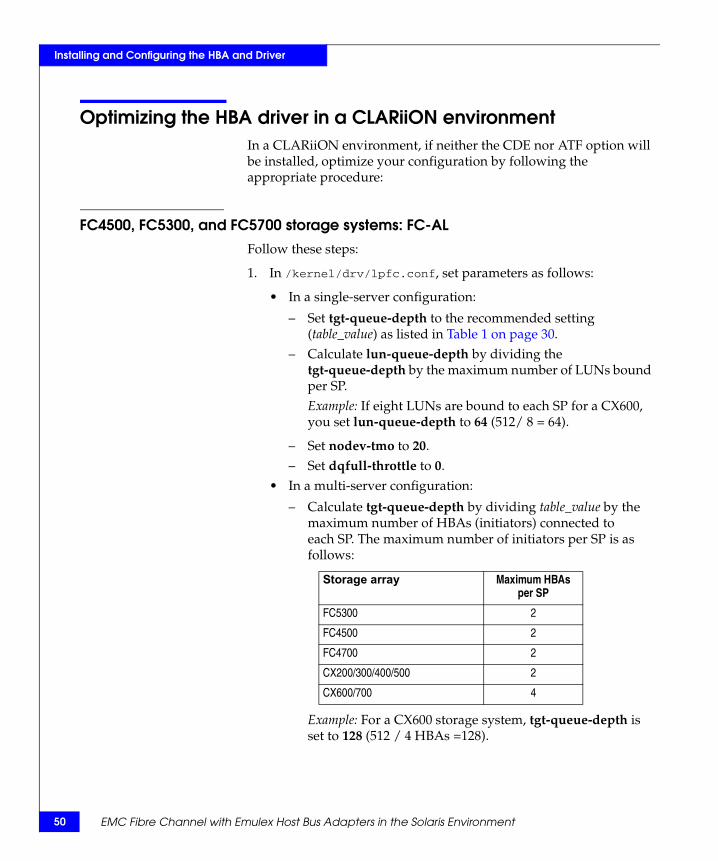
Optimizing the HBA driver in a CLARiiON environmentIn a CLARiiON environment, if neither the CDE nor ATF option will be installed, optimize your configuration by following the appropriate procedure:
FC4500, FC5300, and FC5700 storage systems: FC-AL
Follow these steps:
1. In /kernel/drv/lpfc.conf, set parameters as follows:
• In a single-server configuration:
– Set tgt-queue-depth to the recommended setting (table_value) as listed in Table 1 on page 30.
– Calculate lun-queue-depth by dividing the tgt-queue-depth by the maximum number of LUNs bound per SP.Example: If eight LUNs are bound to each SP for a CX600, you set lun-queue-depth to 64 (512/ 8 = 64).
– Set nodev-tmo to 20.– Set dqfull-throttle to 0.
• In a multi-server configuration:
– Calculate tgt-queue-depth by dividing table_value by the maximum number of HBAs (initiators) connected to each SP. The maximum number of initiators per SP is as follows:
Example: For a CX600 storage system, tgt-queue-depth is set to 128 (512 / 4 HBAs =128).
Storage array Maximum HBAs per SP
FC5300 2
FC4500 2
FC4700 2
CX200/300/400/500 2
CX600/700 4
EMC Fibre Channel with Emulex Host Bus Adapters in the Solaris Environment

Installing and Configuring the HBA and Driver
– Calculate lun-queue-depth by dividing the tgt-queue-depth by the maximum number of LUNs bound per SP.Example: If 10 LUNs are bound to each SP in CX600 storage system, you would set this variable to 13 (128/ 10).
– Set nodev-tmo to 20.– Set dqfull-throttle to 0.
2. Reboot the server (with a standard reboot) to make your changes take effect:
Reboot
FC4500, FC4700, and CX-Series storage systems: FC-SWFollow these steps:
1. In /kernel/drv/lpfc.conf, set parameters as follows:
• Calculate tgt-queue-depth by dividing 2000 (or 256 for the FC4500) by the maximum number of HBAs (initiators) that could have access to Storage Groups on each storage system.
Example (FC4700/CX600): If the fabric consists of four servers (each with two HBAs), each connected to one SP in each storage system through switches, you set the value to 250 (2000/8).
Example (FC4500): If the fabric consists of four servers (each with two HBAs), each connected to one SP in each storage system through switches, you set the value to 32 (256/8).
• Calculate lun-queue-depth by dividing the tgt-queue-depth by the number of LUNs contained in the largest Storage Group to be accessed from the host being configured.
Example: If this host has access to two CX600 storage systems on the fabric with a Storage Group on each storage system, you divide tgt-queue-depth by the number of LUNs in the largest Storage Group. If the largest Storage Group has eight LUNs, you would set this variable to 32 (250/8).
Note: CDE or ATF sets other parameter values after you add persistent bindings. Refer to the EMC Navisphere Server Software for Solaris Administrator’s Guide (P/N 069001068) for more information on these parameters and their values.
Optimizing the HBA driver in a CLARiiON environment 51

52
Installing and Configuring the HBA and Driver
2. Reboot the server (with a standard reboot) to make your changes take effect:
Reboot
C3400/3500 storage systems1. In /kernel/drv/lpfc.conf, set parameters as follows:
• In a single-server configuration:
– Set tgt-queue-depth to 128. – Calculate lun-queue-depth by dividing the
tgt-queue-depth (in this case 128) by the maximum number of LUNs bound per SP.Example: If four LUNs are bound to each SP, you would set this variable to 32 (128 / 4 = 32).
– Set nodev-tmo to 20.– Set dqfull-throttle to 0.
• In a dual-server configuration:
– Set tgt-queue-depth to 64, allowing each initiator 64 outstanding I/Os per SP.
– Calculate lun-queue-depth by dividing the tgt-queue-depth (in this case 64) by the maximum number of LUNs bound per SP.Example: If four LUNs are bound to each SP, you would set this variable to 16 (64 / 4 = 16).
– Set nodev-tmo to 20.– Set dqfull-throttle to 0.
2. Reboot the server (with a standard reboot) to make your changes take effect:
Reboot
EMC Fibre Channel with Emulex Host Bus Adapters in the Solaris Environment
Installing and Configuring the HBA and Driver
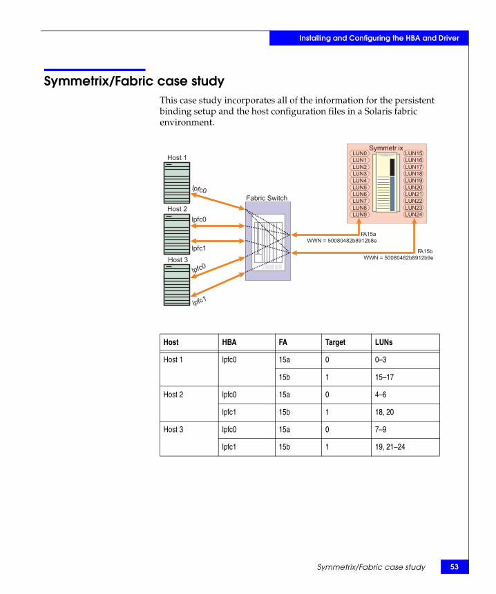
Symmetrix/Fabric case studyThis case study incorporates all of the information for the persistent binding setup and the host configuration files in a Solaris fabric environment.
_
Host 3
Symmetr ix
Fabric Switch
Host 2
FA15a
WWN = 50080482b8912b8e
LUN15
LUN16
LUN18
LUN17
LUN19
LUN21
LUN20
LUN22
LUN24
LUN23
LUN0
LUN1
LUN3
LUN2
LUN4
LUN6
LUN5
LUN7
LUN9
LUN8
Host 1
FA15b
WWN = 50080482b8912b9e
lpfc1
lpfc0
lpfc0
lpfc1
lpfc0
Host HBA FA Target LUNs
Host 1 lpfc0 15a 0 0–3
15b 1 15–17
Host 2 lpfc0 15a 0 4–6
lpfc1 15b 1 18, 20
Host 3 lpfc0 15a 0 7–9
lpfc1 15b 1 19, 21–24
Symmetrix/Fabric case study 53
54
Installing and Configuring the HBA and Driver
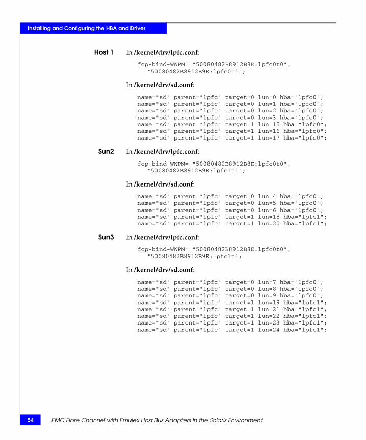
Host 1 In /kernel/drv/lpfc.conf:
fcp-bind-WWPN= "50080482B8912B8E:lpfc0t0", "50080482B8912B9E:lpfc0t1";
In /kernel/drv/sd.conf:
name="sd" parent="lpfc" target=0 lun=0 hba="lpfc0";name="sd" parent="lpfc" target=0 lun=1 hba="lpfc0";name="sd" parent="lpfc" target=0 lun=2 hba="lpfc0";name="sd" parent="lpfc" target=0 lun=3 hba="lpfc0";name="sd" parent="lpfc" target=1 lun=15 hba="lpfc0";name="sd" parent="lpfc" target=1 lun=16 hba="lpfc0";name="sd" parent="lpfc" target=1 lun=17 hba="lpfc0";
Sun2 In /kernel/drv/lpfc.conf:
fcp-bind-WWPN= "50080482B8912B8E:lpfc0t0", "50080482B8912B9E:lpfc1t1";
In /kernel/drv/sd.conf:
name="sd" parent="lpfc" target=0 lun=4 hba="lpfc0";name="sd" parent="lpfc" target=0 lun=5 hba="lpfc0";name="sd" parent="lpfc" target=0 lun=6 hba="lpfc0";name="sd" parent="lpfc" target=1 lun=18 hba="lpfc1";name="sd" parent="lpfc" target=1 lun=20 hba="lpfc1";
Sun3 In /kernel/drv/lpfc.conf:
fcp-bind-WWPN= "50080482B8912B8E:lpfc0t0","50080482B8912B9E:lpfc1t1;
In /kernel/drv/sd.conf:
name="sd" parent="lpfc" target=0 lun=7 hba="lpfc0";name="sd" parent="lpfc" target=0 lun=8 hba="lpfc0";name="sd" parent="lpfc" target=0 lun=9 hba="lpfc0";name="sd" parent="lpfc" target=1 lun=19 hba="lpfc1";name="sd" parent="lpfc" target=1 lun=21 hba="lpfc1";name="sd" parent="lpfc" target=1 lun=22 hba="lpfc1";name="sd" parent="lpfc" target=1 lun=23 hba="lpfc1";name="sd" parent="lpfc" target=1 lun=24 hba="lpfc1";
EMC Fibre Channel with Emulex Host Bus Adapters in the Solaris Environment
3Invisible Body Tag
Solaris hosts have been qualified for booting from EMC storage array devices interfaced through Fibre Channel as described in the EMC Support Matrix. This chapter describes the process to configure a storage array device as a boot device.
◆ Configuring a Symmetrix boot device ............................................ 56◆ Configuring a CLARiiON boot device ........................................... 65
Configuring a BootDevice on theStorage Array
Configuring a Boot Device on the Storage Array 55
56
Configuring a Boot Device on the Storage Array
Configuring a Symmetrix boot deviceBoot support for Symmetrix is available to Emulex HBAs in Solaris hosts as described in the EMC Support Matrix.
Requirements
The designated Symmetrix boot device must meet the following requirements:
◆ The boot device must have enough disk space to hold the Solaris operating system.
◆ For better performance, the boot device should not share the spindle with any other devices. For example, assume devices 304, 203, 405, and 103 occupy physical device C1M1. If the device 203 is being used for booting, no hosts should use device 304, 405, or 103.
◆ The boot device must have the similar partition structures, and each partition must be at least as large as the source partition (the partition from where the image of the partition is being copied).
◆ The installation requires a host drive that will act as the source of the image for the Symmetrix boot drive.
◆ The installation requires administrator understanding of the data backup from the host internal boot drive to the Symmetrix device.
The procedure described in this section assumes that you have installed the Emulex HBA(s), driver(s), and Symmetrix device (over arbitrated loop) onto the Solaris host, and that the Solaris operating system sees the Fibre Channel drives.
If necessary, update the HBA firmware and Open Boot support to at least the minimum levels shown in the previous table.
ProcedureFollow these steps (described in detail later) to configure a boot device:
◆ Verify Symmetrix information
◆ Configure partitions
◆ Create a file system
EMC Fibre Channel with Emulex Host Bus Adapters in the Solaris Environment
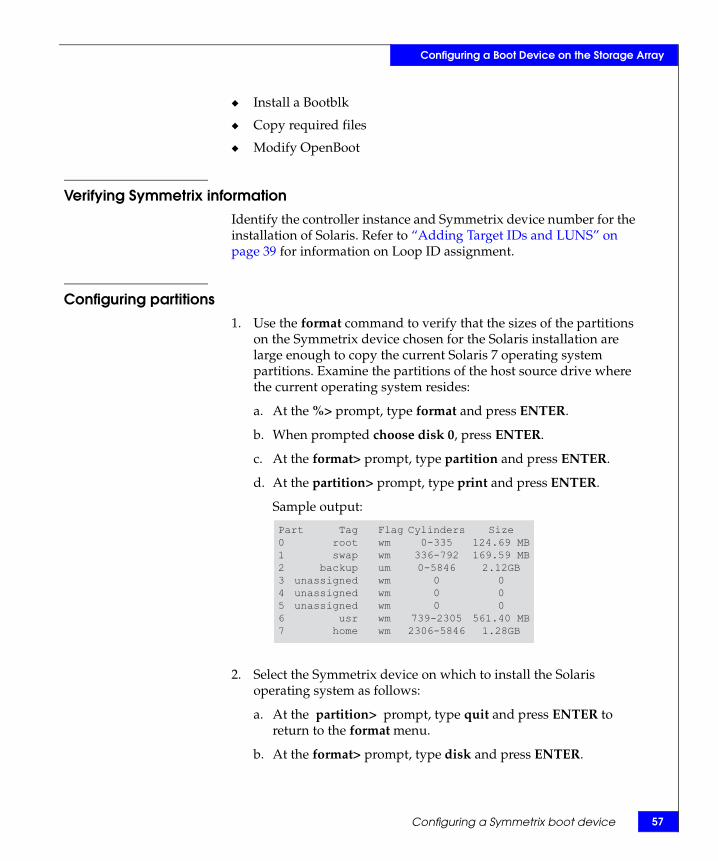
Configuring a Boot Device on the Storage Array
◆ Install a Bootblk
◆ Copy required files
◆ Modify OpenBoot
Verifying Symmetrix informationIdentify the controller instance and Symmetrix device number for the installation of Solaris. Refer to “Adding Target IDs and LUNS” on page 39 for information on Loop ID assignment.
Configuring partitions1. Use the format command to verify that the sizes of the partitions
on the Symmetrix device chosen for the Solaris installation are large enough to copy the current Solaris 7 operating system partitions. Examine the partitions of the host source drive where the current operating system resides:
a. At the %> prompt, type format and press ENTER.
b. When prompted choose disk 0, press ENTER.
c. At the format> prompt, type partition and press ENTER.
d. At the partition> prompt, type print and press ENTER.
Sample output:
2. Select the Symmetrix device on which to install the Solaris operating system as follows:
a. At the partition> prompt, type quit and press ENTER to return to the format menu.
b. At the format> prompt, type disk and press ENTER.
Part0
1
2
34
5
67
Tagrootswap
backupunassignedunassignedunassigned
usrhome
Flagwmwmumwmwmwmwmwm
Cylinders0-335
336-7920-5846
0
0
0
739-23052306-5846
Size124.69 MB169.59 MB2.12GB
0
0
0
561.40 MB1.28GB
Configuring a Symmetrix boot device 57
58
Configuring a Boot Device on the Storage Array
c. Type 1 and press ENTER when information similar to the following appears:
3. Repartition the Symmetrix device (if necessary) to model the partition information from the host source drive in order to match the drive configuration.
a. At the format prompt, type partition and press ENTER.
b. At the partition prompt, type modify and press ENTER.
c. After the partition in the Symmetrix device has been created, type modify and press ENTER at the format prompt.
Creating file systemsCreate file systems on the required partitions in the designated Symmetrix boot device.
Below is an example in which the operating system is being copied to a Symmetrix Device of Target 3 LUN 0 on controller 1:
To use a different Symmetrix Device, change t3 to t<Symmetrix Device target number>. To use a different controller, change c1 to c<controller number>. You must create both the root partition (slice 0) and the /usr partition (slice 6). You should also create other partitions (/export/home, /var, /opt) to mirror the current layout. Use the newfs command to create the file systems.
Installing a bootblk
Install a bootblk (the information required by the host to boot the OS) on the root partition of the Symmetrix boot device.
AVAILABLE SELECTIONS...1. c1t0d0 <EMC-SYMMETRIX-5265 cyl 4088 alt 2 hd 15_ _sec 64> /sbus@1f,0/fce@1,400000/sd@0,0 ..._specify disk (enter its number):
newfs /dev/rdsk/c1t3d0s0newfs /dev/rdsk/c1t3d0s6newfs /dev/rdsk/c1t3d0s7
EMC Fibre Channel with Emulex Host Bus Adapters in the Solaris Environment
Configuring a Boot Device on the Storage Array
1. Use the 'uname -a' command to determine the architecture of the workstation. This determines the directory in /usr/platform where the bootblk will be found. The example below gives sun4u as the architecture, and subdirectory for /usr/platform.
Example: At the %> prompt, type uname -a and press ENTER to display a line similar to the following:
2. At the %> prompt, enter the following to install a bootblk onto the Symmetrix boot device:
/usr/sbin/installboot /usr/platform/sun4u/lib/fs/ufs/bootblk /dev/rdsk/ c<controller number>t<Symmetrix device target number>d0s0
For example, entering the following installs a bootblk onto a boot device of Target 3 LUN 0 on controller 1:
/usr/sbin/installboot /usr/platform/sun4u/lib/fs/ufs/bootblk /dev/rdsk/c1t3d0s0
Copying required filesUse the ufsdump and ufsrestore commands to copy the required files and directories from the current host source drive to the Symmetrix boot device.
1. At the %> prompt, type mount /dev/dsk/c1t3d0s0 /mnt and press ENTER.
This mounts the root directory of the Symmetrix device to /mnt.
2. Use the ufsdump command to create the required directory structure on the new Symmetrix device and copy the files.
Below is an example where the current operating system is located on /dev/dsk/c0t0d0.
Example: At the %> prompt, type the following and press and press ENTER:
ufsdump 0f - /dev/dsk/c0t0d0s0 |( cd /mnt; ufsrestore rf - )
When the above command completes, the Symmetrix device (c1t3d0s0) will have the complete image of the root partition.
SunOS patriot 5.7 Generic_106541-07 sun4u Sparc SUNW,Ultra -4
Configuring a Symmetrix boot device 59
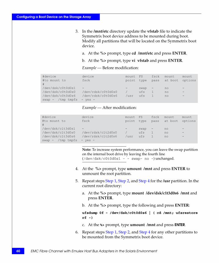
60
Configuring a Boot Device on the Storage Array
3. In the /mnt/etc directory update the vfstab file to indicate the Symmetrix boot device address to be mounted during boot. Modify all partitions that will be located on the Symmetrix boot device.
a. At the %> prompt, type cd /mnt/etc and press ENTER.
b. At the %> prompt, type vi vfstab and press ENTER.
Example — Before modification:
Example — After modification:
Note: To increase system performance, you can leave the swap partition on the internal boot drive by leaving the fourth line (/dev/dsk/c0t0d0s1 - - swap- no -) unchanged.
4. At the %> prompt, type umount /mnt and press ENTER to unmount the root partition.
5. Repeat steps Step 1, Step 2, and Step 4 for the /usr partition. In the current root directory:
a. At the %> prompt, type mount /dev/dsk/c1t3d0s6 /mnt and press ENTER.
b. At the %> prompt, type the following and press ENTER:
ufsdump 0f - /dev/dsk/c0t0d0s6 | ( cd /mnt; ufsrestore
rf -)
c. At the %> prompt, type umount /mnt and press ENTER.
6. Repeat steps Step 1, Step 2, and Step 4 for any other partitions to be mounted from the Symmetrix boot device.
#device device mount FS fsck mount mount#to mount to fsck point type pass at boot options#/dev/dsk/c0t0d0s1 - - swap - no -/dev/dsk/c0t0d0s0 /dev/rdsk/c0t0d0s0 / ufs 1 no -/dev/dsk/c0t0d0s6 /dev/rdsk/c0t0d0s6 /usr ufs 1 no -swap - /tmp tmpfs - yes -
#device device mount FS fsck mount mount#to mount to fsck point type pass at boot options#/dev/dsk/c1t3d0s1 - - swap - no -/dev/dsk/c1t3d0s0 /dev/rdsk/c1t2d0s0 / ufs 1 no -/dev/dsk/c1t3d0s6 /dev/rdsk/c1t2d0s6 /usr ufs 1 no -swap - /tmp tmpfs - yes -
EMC Fibre Channel with Emulex Host Bus Adapters in the Solaris Environment
Configuring a Boot Device on the Storage Array
Modifying OpenBootFollow this procedure to modify OpenBoot:
1. Halt the system and issue a reset to get to the OpenBoot environment:
a. At the %> prompt, type halt and press ENTER.
b. At the OK> prompt, type setenv auto-boot? false and press ENTER, so the system will display the OK> prompt after reset.
c. At the OK> prompt, type reset-all and press ENTER.
2. Specify the topology for the target Fibre Channel boot disk:
a. At the OK> prompt, type the following and press ENTER " <device path name>" select-dev
(Example: " /pci@1f,4000/lpfc@4" select-dev)
b. At the OK> prompt, type the appropriate command and press ENTER:FC-AL: set-fc-alFC-SW: set-ptp
c. At the OK> prompt, type unselect-dev and press ENTER.
3. At the OK> prompt, type reset-all and press ENTER to get to the OpenBoot environment.
4. At the OK> prompt, type printenv boot-device and press ENTER to verify the default boot device. The resulting display should be similar to the following example:
5. Set up the new alias for your local boot disk:
a. At the OK> prompt, type devalias and press ENTER.
b. Note the first appearance of the long path name associated with your local boot disk. For example:disk /pci@1f,4000/scsi@3/disk@0,0
c. At the OK> prompt, type nvalias localdisk <path name> and press ENTER. This assigns the alias localdisk to the local boot disk.
boot-device disk net
Configuring a Symmetrix boot device 61
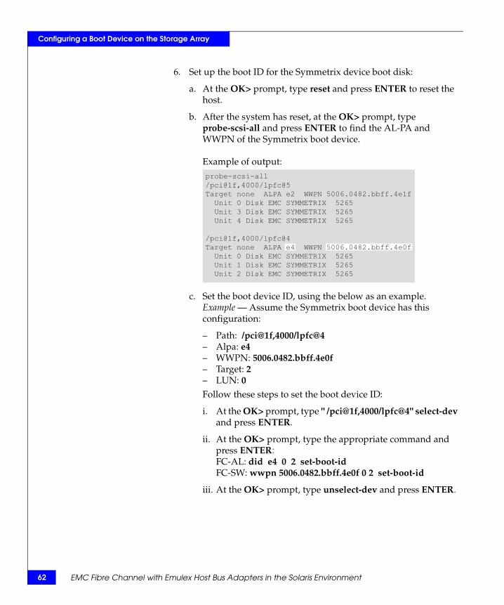
62
Configuring a Boot Device on the Storage Array
6. Set up the boot ID for the Symmetrix device boot disk:
a. At the OK> prompt, type reset and press ENTER to reset the host.
b. After the system has reset, at the OK> prompt, type probe-scsi-all and press ENTER to find the AL-PA and WWPN of the Symmetrix boot device.
Example of output:
c. Set the boot device ID, using the below as an example. Example — Assume the Symmetrix boot device has this configuration:
– Path: /pci@1f,4000/lpfc@4– Alpa: e4– WWPN: 5006.0482.bbff.4e0f– Target: 2– LUN: 0Follow these steps to set the boot device ID:
i. At the OK> prompt, type " /pci@1f,4000/lpfc@4" select-dev and press ENTER.
ii. At the OK> prompt, type the appropriate command and press ENTER:FC-AL: did e4 0 2 set-boot-idFC-SW: wwpn 5006.0482.bbff.4e0f 0 2 set-boot-id
iii. At the OK> prompt, type unselect-dev and press ENTER.
probe-scsi-all/pci@1f,4000/lpfc@5Target none ALPA e2 WWPN 5006.0482.bbff.4e1f Unit 0 Disk EMC SYMMETRIX 5265 Unit 3 Disk EMC SYMMETRIX 5265 Unit 4 Disk EMC SYMMETRIX 5265
/pci@1f,4000/lpfc@4Target none ALPA e4 WWPN 5006.0482.bbff.4e0f Unit 0 Disk EMC SYMMETRIX 5265 Unit 1 Disk EMC SYMMETRIX 5265 Unit 2 Disk EMC SYMMETRIX 5265
EMC Fibre Channel with Emulex Host Bus Adapters in the Solaris Environment
Configuring a Boot Device on the Storage Array
Note: To remove a boot ID just assigned:i. At the OK> prompt, type " /pci@1f,4000/lpfc@4" select-dev
and press ENTER. ii. At the OK> prompt, type remove-boot-id # and press ENTER.iii. At the OK> prompt, type unselect-dev and press ENTER.
7. Set up the alias and boot device for your new Symmetrix boot disk:
a. At the OK> prompt, type nvalias symmdisk <pathname> and press ENTER. Example: nvalias symmdisk /pci@1f,4000/lpfc@4/sd@2,0
b. At the OK> prompt, type nvstore and press ENTER to save your alias.
c. At the OK> prompt, type setenv boot-device symmetrix and press ENTER.
8. Reboot the system with your new boot disk:
a. At the OK> prompt, type setenv auto-boot? true and press ENTER, so your system will not stop at the OK> prompt after reset.
b. At the OK> prompt, type boot symmdisk and press ENTER to boot the host with the Symmetrix boot device.
TroubleshootingThis section lists some possible problems and describes their solutions:
Problem During boot process cannot mount or fsck.
Cause /etc/vfstab file on the Symmetrix boot device did not updated correctly.
Solution At the OK> prompt, type boot localdisk ENTER to boot the system using internal disk. Correct the file /etc/vfstab on the Symmetrix boot device.
Configuring a Symmetrix boot device 63
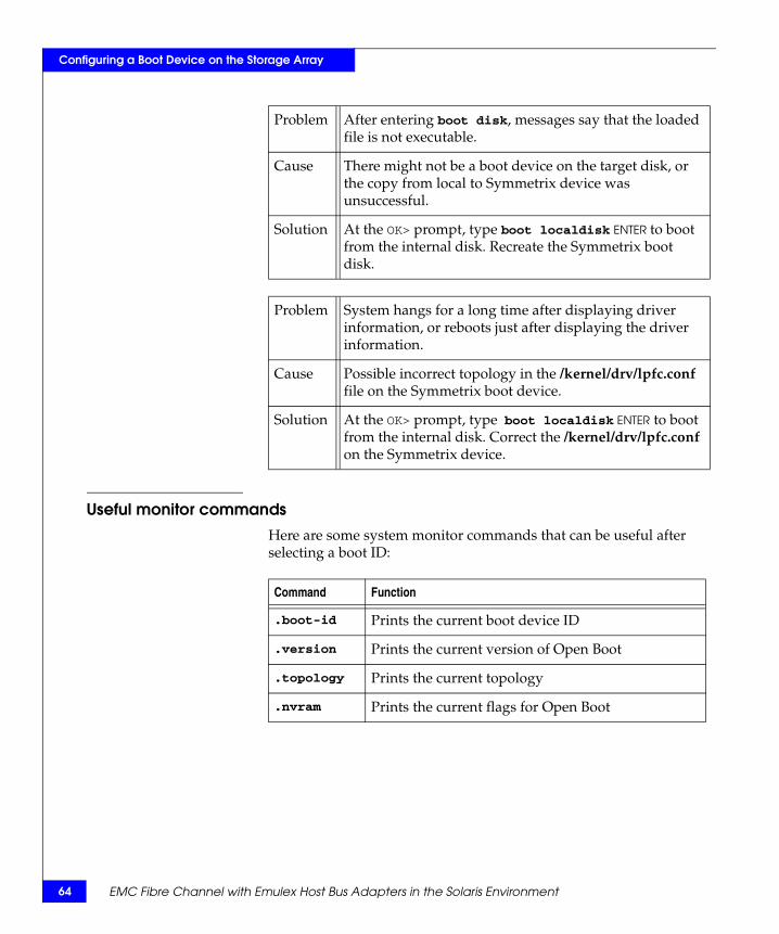
64
Configuring a Boot Device on the Storage Array
Useful monitor commandsHere are some system monitor commands that can be useful after selecting a boot ID:
Problem After entering boot disk, messages say that the loaded file is not executable.
Cause There might not be a boot device on the target disk, or the copy from local to Symmetrix device was unsuccessful.
Solution At the OK> prompt, type boot localdisk ENTER to boot from the internal disk. Recreate the Symmetrix boot disk.
Problem System hangs for a long time after displaying driver information, or reboots just after displaying the driver information.
Cause Possible incorrect topology in the /kernel/drv/lpfc.conf file on the Symmetrix boot device.
Solution At the OK> prompt, type boot localdisk ENTER to boot from the internal disk. Correct the /kernel/drv/lpfc.conf on the Symmetrix device.
Command Function
.boot-id Prints the current boot device ID
.version Prints the current version of Open Boot
.topology Prints the current topology
.nvram Prints the current flags for Open Boot
EMC Fibre Channel with Emulex Host Bus Adapters in the Solaris Environment
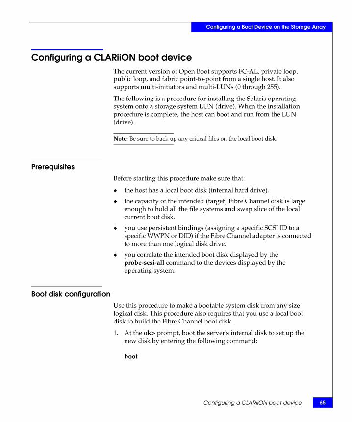
Configuring a Boot Device on the Storage Array
Configuring a CLARiiON boot deviceThe current version of Open Boot supports FC-AL, private loop, public loop, and fabric point-to-point from a single host. It also supports multi-initiators and multi-LUNs (0 through 255).
The following is a procedure for installing the Solaris operating system onto a storage system LUN (drive). When the installation procedure is complete, the host can boot and run from the LUN (drive).
Note: Be sure to back up any critical files on the local boot disk.
Prerequisites
Before starting this procedure make sure that:
◆ the host has a local boot disk (internal hard drive).
◆ the capacity of the intended (target) Fibre Channel disk is large enough to hold all the file systems and swap slice of the local current boot disk.
◆ you use persistent bindings (assigning a specific SCSI ID to a specific WWPN or DID) if the Fibre Channel adapter is connected to more than one logical disk drive.
◆ you correlate the intended boot disk displayed by the probe-scsi-all command to the devices displayed by the operating system.
Boot disk configuration
Use this procedure to make a bootable system disk from any size logical disk. This procedure also requires that you use a local boot disk to build the Fibre Channel boot disk.
1. At the ok> prompt, boot the server's internal disk to set up the new disk by entering the following command:
boot
Configuring a CLARiiON boot device 65
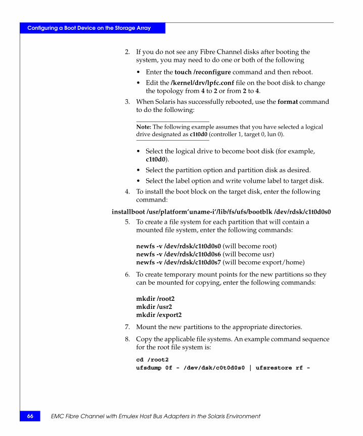
66
Configuring a Boot Device on the Storage Array
2. If you do not see any Fibre Channel disks after booting the system, you may need to do one or both of the following
• Enter the touch /reconfigure command and then reboot.
• Edit the /kernel/drv/lpfc.conf file on the boot disk to change the topology from 4 to 2 or from 2 to 4.
3. When Solaris has successfully rebooted, use the format command to do the following:
Note: The following example assumes that you have selected a logical drive designated as c1t0d0 (controller 1, target 0, lun 0).
• Select the logical drive to become boot disk (for example, c1t0d0).
• Select the partition option and partition disk as desired.
• Select the label option and write volume label to target disk.
4. To install the boot block on the target disk, enter the following command:
installboot /usr/platform’uname-i’/lib/fs/ufs/bootblk /dev/rdsk/c1t0d0s0
5. To create a file system for each partition that will contain a mounted file system, enter the following commands:
newfs -v /dev/rdsk/c1t0d0s0 (will become root)newfs -v /dev/rdsk/c1t0d0s6 (will become usr)newfs -v /dev/rdsk/c1t0d0s7 (will become export/home)
6. To create temporary mount points for the new partitions so they can be mounted for copying, enter the following commands:
mkdir /root2mkdir /usr2mkdir /export2
7. Mount the new partitions to the appropriate directories.
8. Copy the applicable file systems. An example command sequence for the root file system is:
cd /root2
ufsdump 0f - /dev/dsk/c0t0d0s0 | ufsrestore rf -
EMC Fibre Channel with Emulex Host Bus Adapters in the Solaris Environment

Configuring a Boot Device on the Storage Array
9. Edit /root2/etc/vfstab to point to the new boot disk as the physical location of mount points for root, swap, usr, and so on.
Change the current entries as follows:
• /dev/dsk/c0t0d0s0 and /dev/rdsk/c0t0d0s0 to show c1t0d0s0 (root)
• /dev/dsk/c0t0d0s6 and /dev/rdsk/c0t0d0s6 to show c1t0d0s6 (usr)
• /dev/dsk/c0t0d0s7 and /dev/rdsk/c0t0s0s7 to show c1t0d0s7 (export)
• Change entry for swap to show c1t0d0s3
10. If multiple targets exist on a Fibre Channel adapter, you must edit /root2/kernel/drv/lpfc.conf to set up a persistent binding that will ensure that the desired logical disk is always assigned the correct target ID. Refer to the instructions in the lpfc.conf file to set persistent binding.
The disk is now ready to use as a boot disk.
11. Shut down the system.
12. At the ok> prompt enter the following command:
reset-all
Boot setup1. To display the open boot driver version, enter the following
command sequence at the ok> prompt:select /lpfc.versionunselect-dev
2. Change the alias for the current local boot disk from disk to another name (for example, localdisk) as follows:
a. Enter the following command:Devalias
b. Record the long pathname after the first mention of disk, and use that pathname in the following command:nvalias localdisk <path name>
This assigns the alias localdisk to the local boot disk.
Configuring a CLARiiON boot device 67
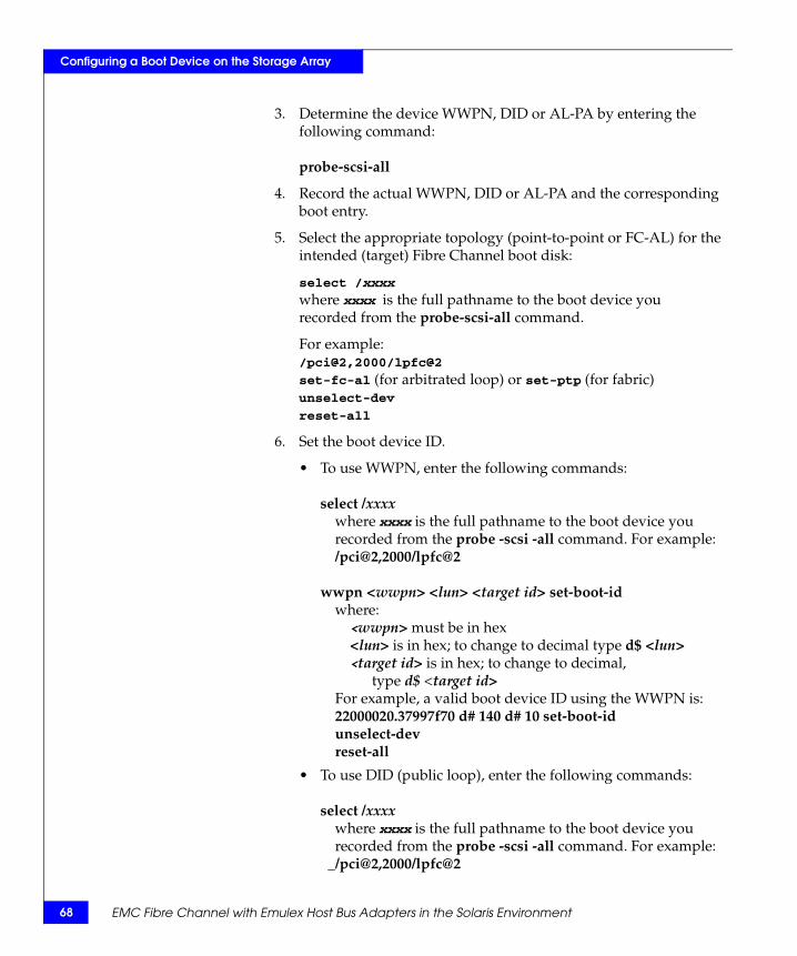
68
Configuring a Boot Device on the Storage Array
3. Determine the device WWPN, DID or AL-PA by entering the following command:
probe-scsi-all
4. Record the actual WWPN, DID or AL-PA and the corresponding boot entry.
5. Select the appropriate topology (point-to-point or FC-AL) for the intended (target) Fibre Channel boot disk:
select /xxxx where xxxx is the full pathname to the boot device yourecorded from the probe-scsi-all command.
For example:/pci@2,2000/lpfc@2
set-fc-al (for arbitrated loop) or set-ptp (for fabric)unselect-dev
reset-all
6. Set the boot device ID.
• To use WWPN, enter the following commands:
select /xxxx__where xxxx is the full pathname to the boot device you__recorded from the probe -scsi -all command. For example:__/pci@2,2000/lpfc@2
wwpn <wwpn> <lun> <target id> set-boot-id__where:____<wwpn> must be in hex____<lun> is in hex; to change to decimal type d$ <lun>____<target id> is in hex; to change to decimal,_______type d$ <target id>__For example, a valid boot device ID using the WWPN is:__22000020.37997f70 d# 140 d# 10 set-boot-id
unselect-devreset-all
• To use DID (public loop), enter the following commands:
select /xxxx__where xxxx is the full pathname to the boot device you__recorded from the probe -scsi -all command. For example:__/pci@2,2000/lpfc@2
EMC Fibre Channel with Emulex Host Bus Adapters in the Solaris Environment
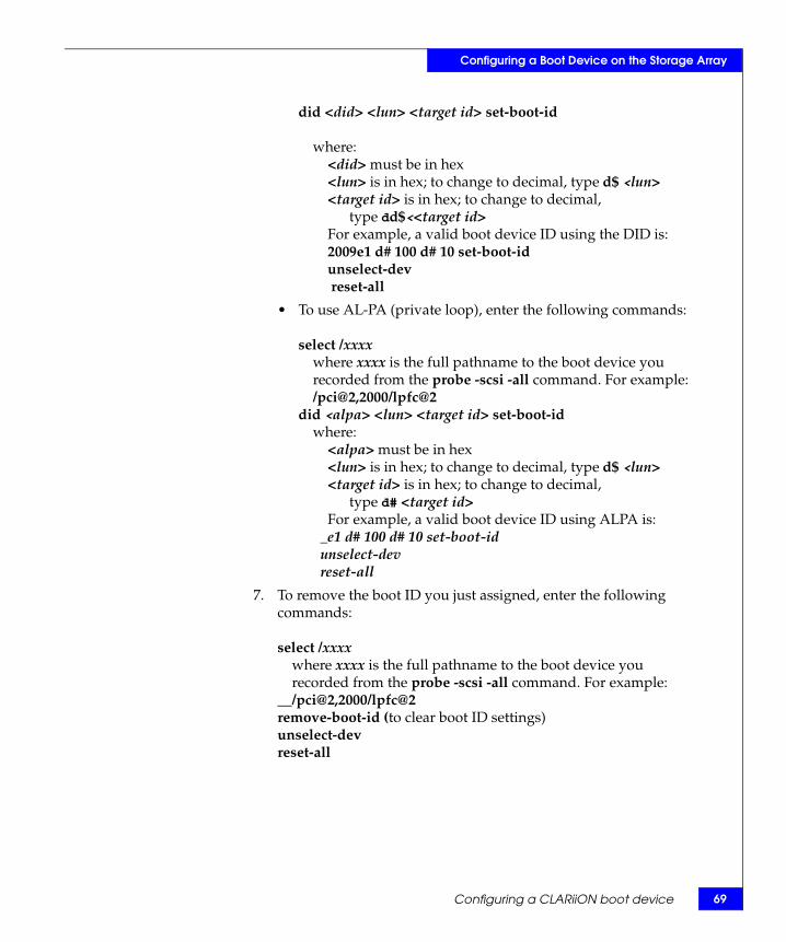
Configuring a Boot Device on the Storage Array
did <did> <lun> <target id> set-boot-id
__where:____<did> must be in hex____<lun> is in hex; to change to decimal, type d$ <lun>____<target id> is in hex; to change to decimal, _______type dd$<<target id>____For example, a valid boot device ID using the DID is:____2009e1 d# 100 d# 10 set-boot-id
unselect-devreset-all
• To use AL-PA (private loop), enter the following commands:
select /xxxx__where xxxx is the full pathname to the boot device you__recorded from the probe -scsi -all command. For example:__/pci@2,2000/lpfc@2did <alpa> <lun> <target id> set-boot-id__where:____<alpa> must be in hex____<lun> is in hex; to change to decimal, type d$ <lun>____<target id> is in hex; to change to decimal, _______type d# <target id>____For example, a valid boot device ID using ALPA is:____e1 d# 100 d# 10 set-boot-id
unselect-devreset-all
7. To remove the boot ID you just assigned, enter the following commands:
select /xxxx__where xxxx is the full pathname to the boot device you__recorded from the probe -scsi -all command. For example:__/pci@2,2000/lpfc@2remove-boot-id (to clear boot ID settings)unselect-devreset-all
Configuring a CLARiiON boot device 69
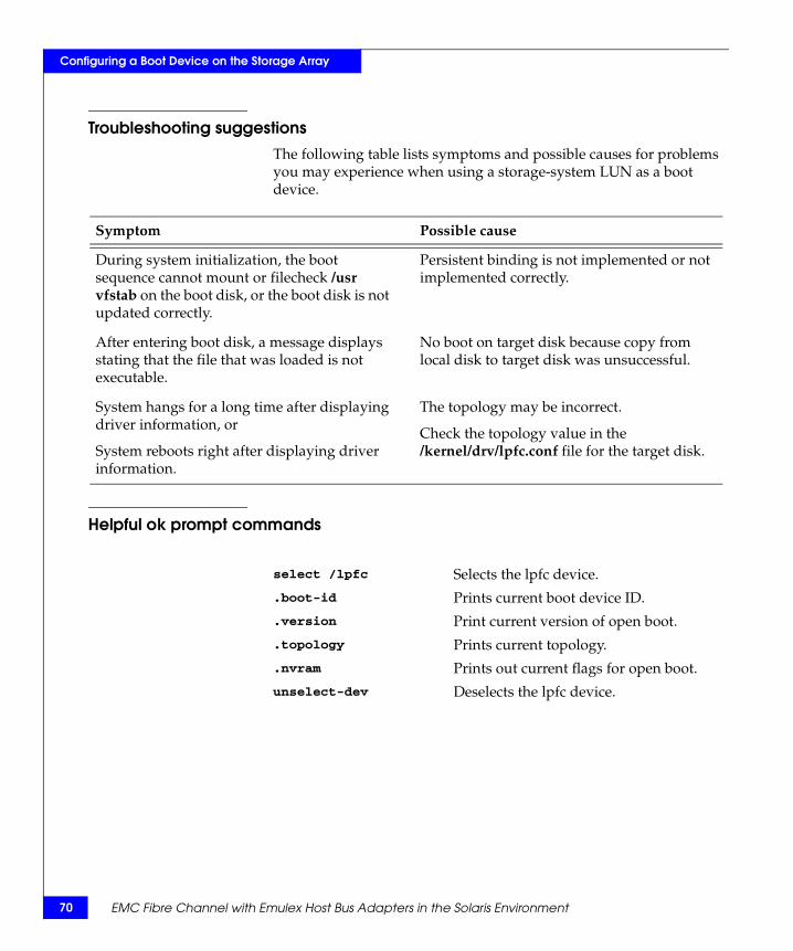
70
Configuring a Boot Device on the Storage Array
Troubleshooting suggestionsThe following table lists symptoms and possible causes for problems you may experience when using a storage-system LUN as a boot device.
Helpful ok prompt commands
Symptom Possible cause
During system initialization, the boot sequence cannot mount or filecheck /usr vfstab on the boot disk, or the boot disk is not updated correctly.
Persistent binding is not implemented or not implemented correctly.
After entering boot disk, a message displays stating that the file that was loaded is not executable.
No boot on target disk because copy from local disk to target disk was unsuccessful.
System hangs for a long time after displaying driver information, or
System reboots right after displaying driver information.
The topology may be incorrect.
Check the topology value in the /kernel/drv/lpfc.conf file for the target disk.
select /lpfc Selects the lpfc device.
.boot-id Prints current boot device ID.
.version Print current version of open boot.
.topology Prints current topology.
.nvram Prints out current flags for open boot.
unselect-dev__ Deselects the lpfc device.
EMC Fibre Channel with Emulex Host Bus Adapters in the Solaris Environment
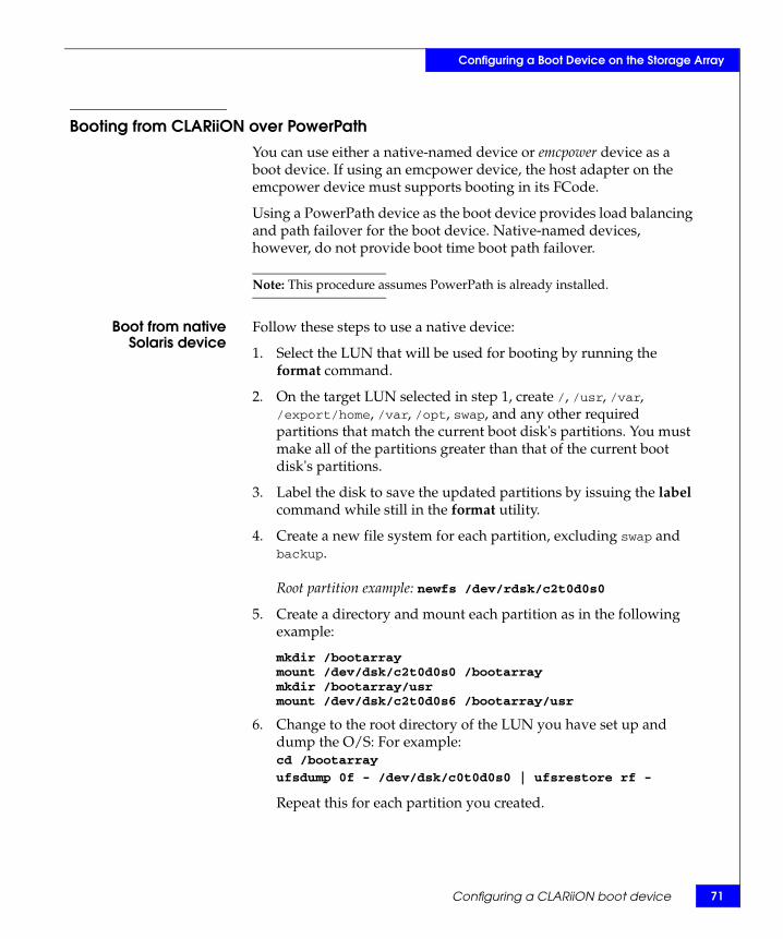
Configuring a Boot Device on the Storage Array
Booting from CLARiiON over PowerPathYou can use either a native-named device or emcpower device as a boot device. If using an emcpower device, the host adapter on the emcpower device must supports booting in its FCode.
Using a PowerPath device as the boot device provides load balancing and path failover for the boot device. Native-named devices, however, do not provide boot time boot path failover.
Note: This procedure assumes PowerPath is already installed.
Boot from nativeSolaris device
Follow these steps to use a native device:
1. Select the LUN that will be used for booting by running the format command.
2. On the target LUN selected in step 1, create /, /usr, /var, /export/home, /var, /opt, swap, and any other required partitions that match the current boot disk's partitions. You must make all of the partitions greater than that of the current boot disk's partitions.
3. Label the disk to save the updated partitions by issuing the label command while still in the format utility.
4. Create a new file system for each partition, excluding swap and backup.
Root partition example: newfs /dev/rdsk/c2t0d0s0
5. Create a directory and mount each partition as in the following example:
mkdir /bootarraymount /dev/dsk/c2t0d0s0 /bootarraymkdir /bootarray/usrmount /dev/dsk/c2t0d0s6 /bootarray/usr
6. Change to the root directory of the LUN you have set up and dump the O/S: For example:cd /bootarray
ufsdump 0f - /dev/dsk/c0t0d0s0 | ufsrestore rf -
Repeat this for each partition you created.
Configuring a CLARiiON boot device 71
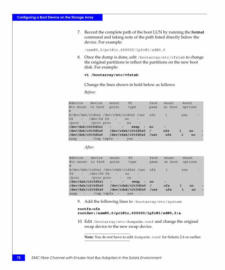
72
Configuring a Boot Device on the Storage Array
7. Record the complete path of the boot LUN by running the format command and taking note of the path listed directly below the device. For example:
/ssm@0,0/pci@1c,600000/lpfc@1/sd@0,0
8. Once the dump is done, edit /bootarray/etc/vfstab to change the original partitions to reflect the partitions on the new boot disk. For example:
vi /bootarray/etc/vfstab
Change the lines shown in bold below as follows:
Before:
After:
9. Add the following lines to /bootarray/etc/system:
rootfs:ufsrootdev:/ssm@0,0/pci@1c,600000/lpfc@1/sd@0,0:a
10. Edit /bootarray/etc/dumpadm.conf and change the original swap device to the new swap device.
Note: You do not have to edit dumpadm.conf for Solaris 2.6 or earlier.
#device device mount FS fsck mount mount#to mount to fsck point type pass at boot options##/dev/dsk/c1d0s2 /dev/rdsk/c1d0s2 /usr ufs 1 yes -fd - /dev/fd fd - no -/proc - /proc proc - no -/dev/dsk/c0t0d0s1 - - swap - no -/dev/dsk/c0t0d0s0 /dev/rdsk/c0t0d0s0 / ufs 1 no -/dev/dsk/c0t0d0s6 /dev/rdsk/c0t0d0s6 /usr ufs 1 no -swap - /tmp tmpfs - yes -
#device device mount FS fsck mount mount#to mount to fsck point type pass at boot options##/dev/dsk/c1d0s2 /dev/rdsk/c1d0s2 /usr ufs 1 yes -fd - /dev/fd fd - no -/proc - /proc proc - no -/dev/dsk/c2t0d0s1 - - swap - no -/dev/dsk/c2t0d0s0 /dev/rdsk/c2t0d0s0 / ufs 1 no -/dev/dsk/c2t0d0s6 /dev/rdsk/c2t0d0s6 /usr ufs 1 no -swap - /tmp tmpfs - yes -
EMC Fibre Channel with Emulex Host Bus Adapters in the Solaris Environment

Configuring a Boot Device on the Storage Array
11. Install the boot block on the new boot device by running the following:
installboot /usr/platform/`uname -i`/lib/fs/ufs/bootblk /dev/rdsk/c2t0d0s0
12. Bring the host down to the OBP by issuing the halt command.
13. While in OBP, issue the reset-all command.
14. Issue the show-devs command, and select the correct path to the device to be used as the new boot device. For example:
" /ssm@0,0/pci@1c,600000/lpfc@1" select-dev
15. To set the correct topology, type the following and press ENTER:
• Fabric: set-ptp
• Loop: set-fc-al
16. To display all Fibre Channel devices along with WWPN of the target SP from which you are booting, issue the show-children command.
17. Set the boot ID of the new boot device:
a. Make note of the actual WWPN, DID, or ALPA returned from the show-children comand, and copy down the corresponding boot entry.
b. Set the boot ID:
18. Create an alias for the new boot device:
nvalias emcboot /ssm@0,0/pci@1c,600000/lpfc@1/sd@0,0:anvstore
19. You are now ready to boot:
unselect-devreset-allboot emcboot
• For point-to-point (WWPN):wwpn <WWPN> <LUN> <target ID> set-boot-id
• For public loop (DID):did <DID> <LUN> <target ID> set-boot-id
• For private loop (ALPA):did <ALPA> <LUN> <target ID> set-boot-id
Configuring a CLARiiON boot device 73
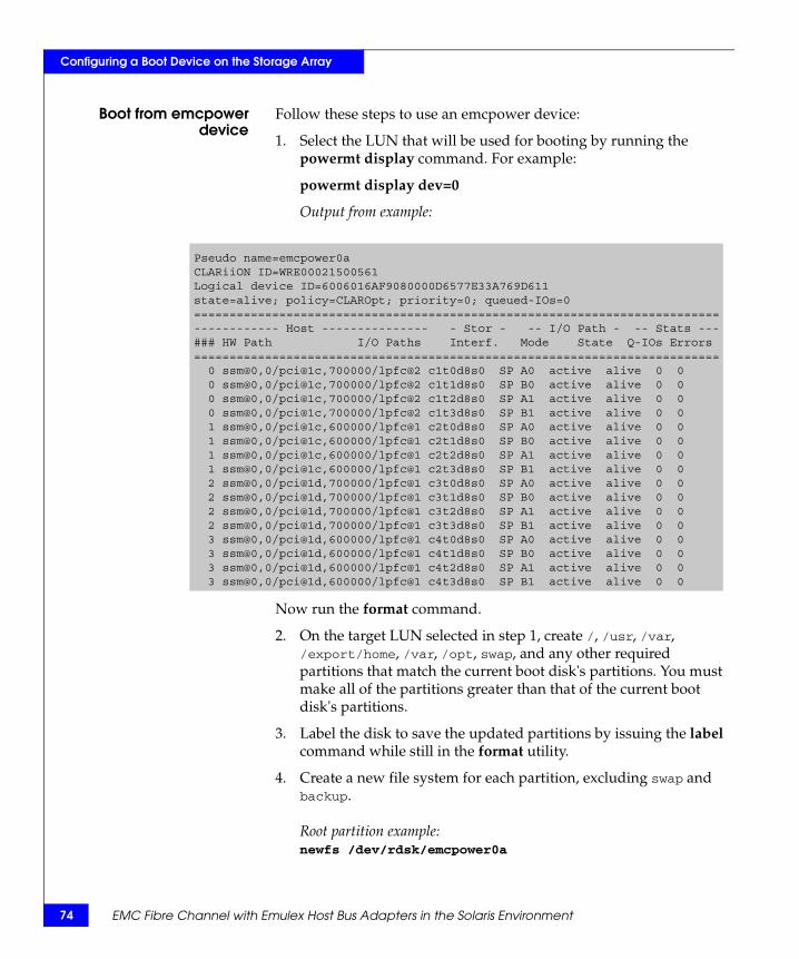
74
Configuring a Boot Device on the Storage Array
Boot from emcpowerdevice
Follow these steps to use an emcpower device:
1. Select the LUN that will be used for booting by running the powermt display command. For example:
powermt display dev=0
Output from example:
Now run the format command.
2. On the target LUN selected in step 1, create /, /usr, /var, /export/home, /var, /opt, swap, and any other required partitions that match the current boot disk's partitions. You must make all of the partitions greater than that of the current boot disk's partitions.
3. Label the disk to save the updated partitions by issuing the label command while still in the format utility.
4. Create a new file system for each partition, excluding swap and backup.
Root partition example: newfs /dev/rdsk/emcpower0a
Pseudo name=emcpower0aCLARiiON ID=WRE00021500561Logical device ID=6006016AF9080000D6577E33A769D611state=alive; policy=CLAROpt; priority=0; queued-IOs=0==========================================================================------------ Host --------------- - Stor - -- I/O Path - -- Stats ---### HW Path I/O Paths Interf. Mode State Q-IOs Errors========================================================================== 0 ssm@0,0/pci@1c,700000/lpfc@2 c1t0d8s0 SP A0 active alive 0 0 0 ssm@0,0/pci@1c,700000/lpfc@2 c1t1d8s0 SP B0 active alive 0 0 0 ssm@0,0/pci@1c,700000/lpfc@2 c1t2d8s0 SP A1 active alive 0 0 0 ssm@0,0/pci@1c,700000/lpfc@2 c1t3d8s0 SP B1 active alive 0 0 1 ssm@0,0/pci@1c,600000/lpfc@1 c2t0d8s0 SP A0 active alive 0 0 1 ssm@0,0/pci@1c,600000/lpfc@1 c2t1d8s0 SP B0 active alive 0 0 1 ssm@0,0/pci@1c,600000/lpfc@1 c2t2d8s0 SP A1 active alive 0 0 1 ssm@0,0/pci@1c,600000/lpfc@1 c2t3d8s0 SP B1 active alive 0 0 2 ssm@0,0/pci@1d,700000/lpfc@1 c3t0d8s0 SP A0 active alive 0 0 2 ssm@0,0/pci@1d,700000/lpfc@1 c3t1d8s0 SP B0 active alive 0 0 2 ssm@0,0/pci@1d,700000/lpfc@1 c3t2d8s0 SP A1 active alive 0 0 2 ssm@0,0/pci@1d,700000/lpfc@1 c3t3d8s0 SP B1 active alive 0 0 3 ssm@0,0/pci@1d,600000/lpfc@1 c4t0d8s0 SP A0 active alive 0 0 3 ssm@0,0/pci@1d,600000/lpfc@1 c4t1d8s0 SP B0 active alive 0 0 3 ssm@0,0/pci@1d,600000/lpfc@1 c4t2d8s0 SP A1 active alive 0 0 3 ssm@0,0/pci@1d,600000/lpfc@1 c4t3d8s0 SP B1 active alive 0 0
EMC Fibre Channel with Emulex Host Bus Adapters in the Solaris Environment
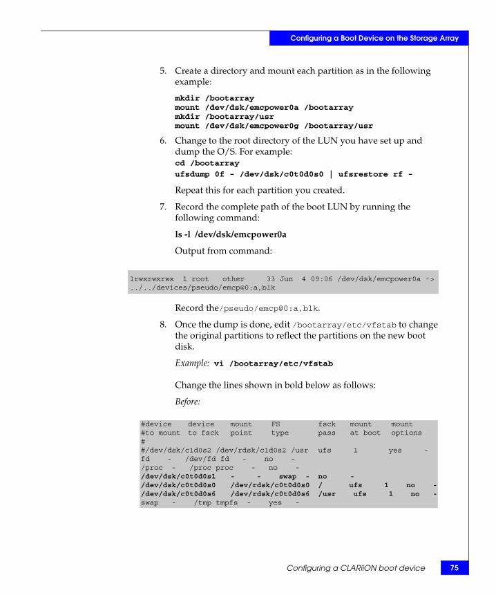
Configuring a Boot Device on the Storage Array
5. Create a directory and mount each partition as in the following example:
mkdir /bootarraymount /dev/dsk/emcpower0a /bootarraymkdir /bootarray/usrmount /dev/dsk/emcpower0g /bootarray/usr
6. Change to the root directory of the LUN you have set up and dump the O/S. For example:cd /bootarray
ufsdump 0f - /dev/dsk/c0t0d0s0 | ufsrestore rf -
Repeat this for each partition you created.
7. Record the complete path of the boot LUN by running the following command:
ls -l /dev/dsk/emcpower0a
Output from command:
Record the/pseudo/emcp@0:a,blk.
8. Once the dump is done, edit /bootarray/etc/vfstab to change the original partitions to reflect the partitions on the new boot disk.
Example: vi /bootarray/etc/vfstab
Change the lines shown in bold below as follows:
Before:
lrwxrwxrwx 1 root other 33 Jun 4 09:06 /dev/dsk/emcpower0a ->../../devices/pseudo/emcp@0:a,blk
#device device mount FS fsck mount mount#to mount to fsck point type pass at boot options##/dev/dsk/c1d0s2 /dev/rdsk/c1d0s2 /usr ufs 1 yes -fd - /dev/fd fd - no -/proc - /proc proc - no -/dev/dsk/c0t0d0s1 - - swap - no -/dev/dsk/c0t0d0s0 /dev/rdsk/c0t0d0s0 / ufs 1 no -/dev/dsk/c0t0d0s6 /dev/rdsk/c0t0d0s6 /usr ufs 1 no -swap - /tmp tmpfs - yes -
Configuring a CLARiiON boot device 75

76
Configuring a Boot Device on the Storage Array
After:
9. Add the following lines to the end of /bootarray/etc/system:
forceload: drv/sdforceload: drv/emcprootfs:ufsrootdev:/pseudo/emcp@0:a,blk
10. Edit /bootarray/etc/dumpadm.conf and change the original swap device to the new swap device.
Note: You do not have to edit dumpadm.conf for Solaris 2.6 or earlier.
11. Install the boot block on the new boot device by running the following:
installboot /usr/platform/`uname -i`/lib/fs/ufs/bootblk /dev/rdsk/emcpower0a
12. To find the boot device information to reconfigure the boot disk EEPROM setting, issue the powermt display command as you did in step 1, and issue ls -l on any one of the devices that appears in the output of powermt display. For example:
ls -l c1t0d0s0
Output from command:
Record the ssm@0,0/pci@1c,700000/lpfc@2/sd@0,8:a.
13. Bring the host down to the OBP by issuing the halt command.
14. While in OBP, issue the reset-all command.
15. Issue the show-devs command, and select the correct path to the device to be used as the new boot device (recorded in step Step 11).
#device device mount FS fsck mount mount#to mount to fsck point type pass at boot options##/dev/dsk/c1d0s2 /dev/rdsk/c1d0s2 /usr ufs 1 yes -fd - /dev/fd fd - no -/proc - /proc proc - no -/dev/dsk/emcpower0b - - swap - no -/dev/dsk/emcpower0a /dev/rdsk/emcpower0a / ufs 1 no -/dev/dsk/emcpower0g /dev/rdsk/emcpower0g /usr ufs 1 no -swap - /tmp tmpfs - yes -
lrwxrwxrwx 1 root other 33 Jun 4 09:06 /dev/dsk/c1t0d0s0 ->..//devices/ssm@0,0/pci@1c,700000/lpfc@2/sd@0,8:a
EMC Fibre Channel with Emulex Host Bus Adapters in the Solaris Environment
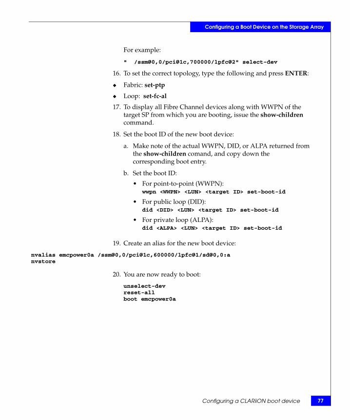
Configuring a Boot Device on the Storage Array
For example:
" /ssm@0,0/pci@1c,700000/lpfc@2" select-dev
16. To set the correct topology, type the following and press ENTER:
◆ Fabric: set-ptp
◆ Loop: set-fc-al
17. To display all Fibre Channel devices along with WWPN of the target SP from which you are booting, issue the show-children command.
18. Set the boot ID of the new boot device:
a. Make note of the actual WWPN, DID, or ALPA returned from the show-children comand, and copy down the corresponding boot entry.
b. Set the boot ID:
19. Create an alias for the new boot device:
nvalias emcpower0a /ssm@0,0/pci@1c,600000/lpfc@1/sd@0,0:anvstore
20. You are now ready to boot:
unselect-devreset-allboot emcpower0a
• For point-to-point (WWPN):wwpn <WWPN> <LUN> <target ID> set-boot-id
• For public loop (DID):did <DID> <LUN> <target ID> set-boot-id
• For private loop (ALPA):did <ALPA> <LUN> <target ID> set-boot-id
Configuring a CLARiiON boot device 77

78
Configuring a Boot Device on the Storage Array
EMC Fibre Channel with Emulex Host Bus Adapters in the Solaris Environment
Index
Symbols/etc/system, editing 41
Bboot device, CLARiiON, configuring 65boot device, Symmetrix, configuring 56
Ccase study, Symmetrix/fabric 53
Ddriver instance number, determining
(CLARiiON) 38driver, HBA
installing 15obtaining 15optimizing in CLARiiON environment 50upgrading
PCI 23SBus 19
EEMC Fibre Channel, incorporating 27Emulex/Solaris environment 10etc/system, editing 41
Ffabric environment, preparing for 27failover software, CLARiiON, removing 15FCode, HBA, updating 45firmware, HBA, updating 44
HHBA driver. See driver, HBAHBA, replacing (CLARiiON) 49
Iinstance number, driver, determining
(CLARiiON) 38
Llabeling devices 43lpfc.conf, editing 29
Ppartitioning devices 43persistent binding 27
SSolaris/Emulex environment 10
Uupgrading the driver
PCI 23SBus 19
Zzone, single-HBA, creating (CLARiiON) 47zoning 11
EMC Fibre Channel with Emulex Host Bus Adapters in the Solaris Environment 79

80
Index
EMC Fibre Channel with Emulex Host Bus Adapters in the Solaris Environment