emc rf solution - tdk...solutions, adding it at the top of the traceability hierarchy in your...
TRANSCRIPT

EMC RF Solution
Electromagnetic Wave Anechoic Chambers
Electromagnetic Wave Absorbers
EMC Measurement and Evaluation System
1/ 13
All specifications are subject to change without notice.
Contents Update : AUGUST 2014
2 / 13 en/20140815
Achievements and challenges
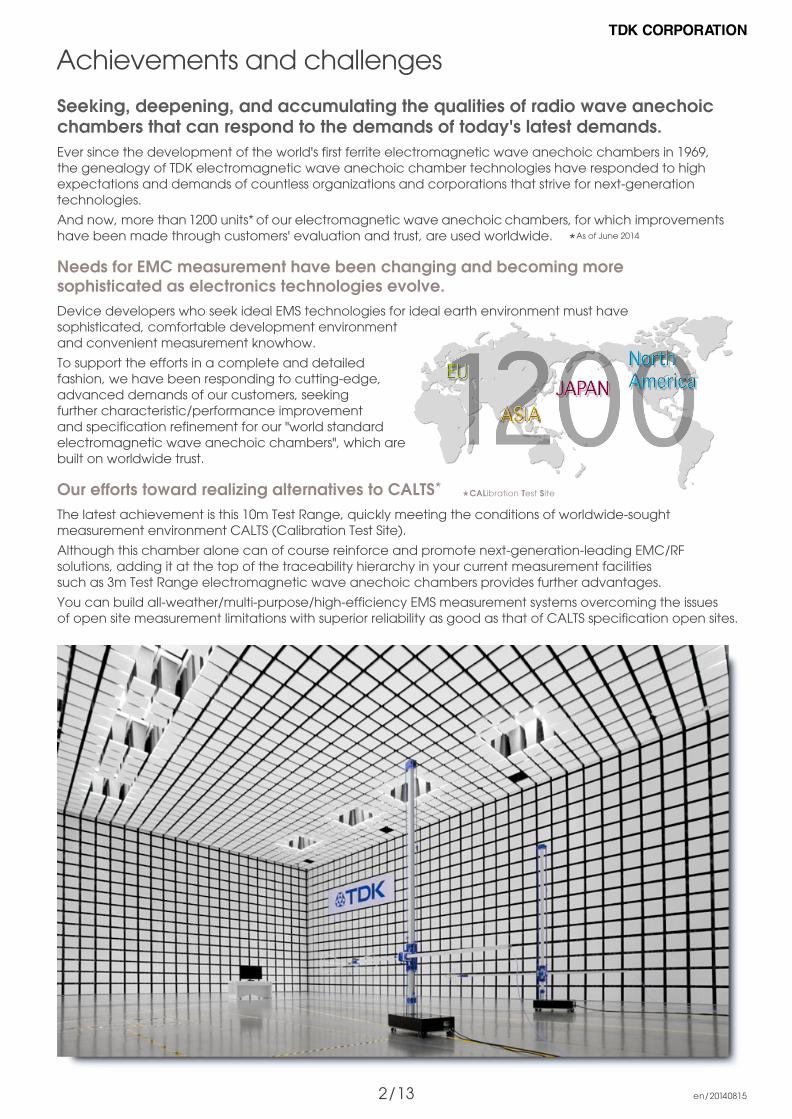
Seeking, deepening, and accumulating the qualities of radio wave anechoic chambers that can respond to the demands of today's latest demands. Ever since the development of the world's first ferrite electromagnetic wave anechoic chambers in 1969, the genealogy of TDK electromagnetic wave anechoic chamber technologies have responded to high expectations and demands of countless organizations and corporations that strive for next-generation technologies.
And now, more than 1200 units* of our electromagnetic wave anechoic chambers, for which improvements have been made through customers' evaluation and trust, are used worldwide.
Needs for EMC measurement have been changing and becoming more sophisticated as electronics technologies evolve.Device developers who seek ideal EMS technologies for ideal earth environment must have sophisticated, comfortable development environment and convenient measurement knowhow.
To support the efforts in a complete and detailed fashion, we have been responding to cutting-edge, advanced demands of our customers, seeking further characteristic/performance improvement and specification refinement for our "world standard electromagnetic wave anechoic chambers", which are built on worldwide trust.
Our efforts toward realizing alternatives to CALTS*
The latest achievement is this 10m Test Range, quickly meeting the conditions of worldwide-sought measurement environment CALTS (Calibration Test Site).
Although this chamber alone can of course reinforce and promote next-generation-leading EMC/RF solutions, adding it at the top of the traceability hierarchy in your current measurement facilities such as 3m Test Range electromagnetic wave anechoic chambers provides further advantages.
You can build all-weather/multi-purpose/high-efficiency EMS measurement systems overcoming the issues of open site measurement limitations with superior reliability as good as that of CALTS specification open sites.
�
*CALibration Test Site
* As of June 2014

3 / 15 emcrf_en/20150401
10 100 1000
Site performance evaluation using reference dipole antennas: CISPR16-1-5 CALTS characteristics (Horizontal polarized wave), REFTS characteristics (Vertical polarized wave) Evaluation using antenna calibration test site method stipulated in CISPR16-1-5: Using reference dipole antennas which allow theoretical calculation (moment method and such)
45
40
35
30
25
20
15
Reference Site MethodNew test site evaluation method which replaces NSA (Normalized Site Attenuation)Site evaluation method based on APR (Antenna Pair Reference) / Reference site: Liberty Labs.
Frequency (MHz)10 100
Frequency (MHz)
1000
1
0
- 1
10 100 1000
Site
Att
en
ua
tion
(dB)
45
40
35
30
25
20
15
Frequency (MHz)10 100
Frequency (MHz)
1000De
via
tion
(dB) 1
0
- 1
Horizontal polarized wave
Site
Att
en
ua
tion
(dB)
De
via
tion
(dB)
Measured value(Center)Calculated valueVertical polarized wave
Measured value(Center)Calculated value
Center Front 2m Back 2m Right 2m Left 2m
Horizontal polarized wave
Center Front 2m Back 2m Right 2m Left 2m
Vertical polarized wave
Advantages of CALTS specification/cutting-edge 10m Test Range electromagnetic wave anechoic chambers
Frequency (MHz)10 100 1000
2
1
0
- 1
- 2
Tx =2m
De
via
tion
(dB)
Frequency (MHz)10 100 1000
De
via
tion
(dB)
2
1
0
- 1
- 2
Tx =1.5mFrequency (MHz)
10 100 1000
2
1
0
- 1
- 2
Tx =1m
De
via
tion
(dB)
Frequency (MHz)10 100 1000
De
via
tion
(dB)
2
1
0
- 1
- 2
Tx =1m
Achievements and challenges
The chamber walls and ceilings are structured using cutting - edge IP-250BL (height : 2.5m) hybrid type absorber which realized TDK's best absorbing characteristics. We now have a new performance realm of the 10m Test Range anecho- ic chamber surpassing the world's best standard.
ANSI C63.4 Normalized theoretical site attenuation within 1.3dB was achieved, realizing next-generational electromagnetic environment even more optimal than the attenuation level of the conventional high-performing 10m Test Range electromagnetic wave anechoic chambers (within plus-minus 2.5dB).
CALTS characteristics : within 0.4, 0.8dB. REFTS characteristics : within 0.6dB
Height pattern characteristics : Excellent height pattern characteristics, almost equivalent to theoretical figures and those of open sites were achieved.
Site attenuation uniformity : 6m (evaluated at 50cm intervals each direction of horizontal and vertical) area variable within 1.3dB was was achieved, realizing a superior field uniformity flat which mea- surement environment which surpasses the conventional levels.

4 / 13 ja /20140815
10m test range
Specification example
Shield surface dimension
Inner-wall dimension
Electromagnetic Wave Absorbers
Turntable
* ICM-006-mounted EMS absorbing plate + Fully-automated beneath floor storage device
3m test range
Specification example
Shield surface dimension�
Inner-wall dimension�
Electromagnetic Wave Absorbers�
Turntable
L12 x W8.5 x H6 m
L10.6 x W7.1 x H5.3 m
IB-017(L100 x W100 x T5.2 mm)
IP-065BL (L600 x W600 x H650 mm)
IP-045C (L600 x W600 x H450 mm)*
3 m (1ton)
* Floor-installed EMS-absorbing electromagnetic wave absorber
For evaluation and testing of car-mounted components
Specification example
Shield surface dimension
Inner-wall dimension
Electromagnetic Wave Absorbers
Measurement table for CISPR25
L7 x W6.5 x H4.3 m
L6.5 x W5.5 x H3.5 m
IB-017(L100 x W100 x T5.2 mm)
IP-045BLB (L600 x W600 x H450 mm)
IP-045C (L600 x W600 x H450 mm)
L3000 x W1500 x H900 mm
For evaluation and testing of cars
Specification example
Shield surface dimension
Inner-wall dimension
Electromagnetic Wave Absorbers
Turntable*
For EMC measurement/evaluationElectromagnetic wave anechoic chambers
* Chassis-dynamometer equippedr
REPRESENTATIVE SPECIFICATION EXAMPLE
L25 x W14 x H9 m
L22.4 x W11.4 x H7.7m
IB-017(L100 x W100 x T5.2 mm)
IP-130BLB (L600 x W600 x H1300 mm)
ICM-006 (L100 x W100 x H60 mm)*
3 m (0.5ton)/ 6 m (4 ton) Dual
L16 x W12 x H6.5 m
L14 x W10 x H5.5 m
IB-017(L100 x W100 x T5.2 mm)
IP-090BLB (L600 x W600 x H950 mm)
8m (5 ton)
Site attenuation characteristics30MHz 1GHz : Within 3dB( 5m area)
Site attenuation characteristics30MHz 1GHz : Within 3dB( 3m area)
Site attenuation characteristics30MHz 1GHz : Within 3dB( 5m area)
5 / 15 en_20150401
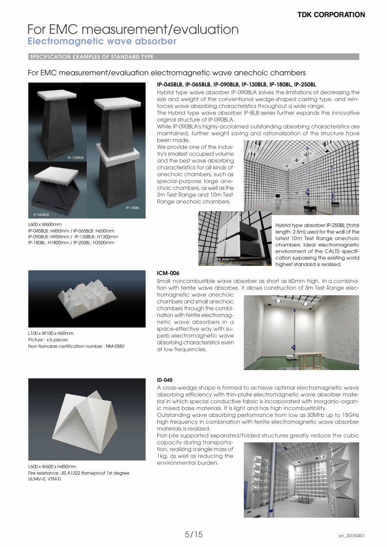
ICM-006Small noncombustible wave absorber as short as 60mm high. In a combina-tion with ferrite wave absorber, it allows construction of 3m Test Range elec-tromagnetic wave anechoic chambers and small anechoic chambers through the combi-nation with ferrite electromag-netic wave absorbers in a space-effective way with su-perb electromagnetic wave absorbing characteristics even at low frequencies.
L600 x W600mm IP-045BLB : H450mm / IP-065BLB : H650mm IP-090BLB : H950mm / IP-130BLB : H1300mmIP-180BL : H1800mm / IP-250BL : H2500mm
ID-045A cross-wedge shape is formed to achieve optimal electromagnetic wave absorbing efficiency with thin-plate electromagnetic wave absorber mate-rial in which special conductive fabric is incorporated with inorganic-organ-ic mixed base materials. It is light and has high incombustibility.Outstanding wave absorbing performance from low as 30MHz up to 18GHz high frequency in combination with ferrite electromagnetic wave absorber materials is realized. Flat-pile supported separated/folded structures greatly reduce the cubic capacity during transporta-tion, realizing a single mass of 1kg, as well as reducing the environmental burden.
IP-180BL
IP-045BLB
IP-130BLB
Hybrid type absorber IP-250BL (total length: 2.5m) used for the wall of the latest 10 m Test Range anechoic chambers. Ideal electromagnetic environment of the CALTS - specifi-cation surpassing the existing world highest standard is realized.
IP-045BLB, IP-065BLB, IP-090BLB, IP-130BLB, IP-180BL, IP-250BLHybrid type wave absorber IP-090BLA solves the limitations of decreasing the size and weight of the conventional wedge-shaped casting type, and rein-forces wave absorbing characteristics throughout a wide range. The Hybrid type wave absorber IP-BLB series further expands the innovative original structure of IP-090BLA.While IP-090BLA's highly-acclaimed outstanding absorbing characteristics are maintained, further weight saving and rationalization of the structure have been made.We provide one of the indus-try's smallest occupied volume and the best wave absorbing characteristics for all kinds of anechoic chambers, such as special-purpose large ane-choic chambers, as well as the 3m Test Range and 10m Test Range anechoic chambers.
L100 x W100 x H60mmPicture : x 6 pieces Non flamable certification number : NM-0582
L600 x W600 x H450mm Fire resistance: JIS A1322 flameproof 1st degreeUL94V-0, VTM-0
For EMC measurement/evaluationElectromagnetic wave absorberSPECIFICATION EXAMPLES OF STANDARD TYPE
For EMC measurement/evaluation electromagnetic wave anechoic chambers
6/ 15 emcrf_en/20150401
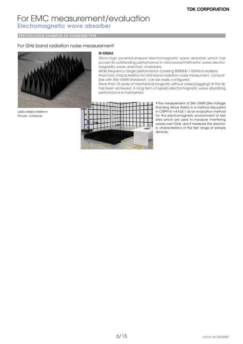
IS-030A2 30cm-high pyramid-shaped electromagnetic wave absorber which has proven its outstanding performance in microwave/millimetric wave electro-magnetic wave anechoic chambers.Wide frequency range performance covering 800MHz-110GHz is realized. Anechoic characteristics for GHz-band radiation noise measument, compat-ible with Site VSWR standard*, can be easily configured. More than 10 years of mechanical longevity without creep (sagging) at the tip has been achieved. A long term of superb electromagnetic wave absorbing performance is maintained.
For EMC measurement/evaluationElectromagnetic wave absorberSPECIFICATION EXAMPLES OF STANDARD TYPE
For GHz band radiation noise measurement
L600 x W600 x H300mm Picture : x 2 pieces
* The measurement of Site VSWR (Site Voltage Standing Wave Ratio) is a method stipulated in CISPR16-1-4 Ed3.1 as an evaluation method for the electromagnetic environment of test sites which are used to measure interfering waves over 1GHz, and it measures the anecho-ic characteristics of the test range of sample devices.

7/ 15 emcrf_en/20150401
Large type for the evaluation of radar and large antennas
Middle-sized type for antenna evaluation
High-precision small type for antenna evaluation
Middle-sized type for performance/diverse communication devices
Specification example
For antenna design/evaluationElectromagnetic wave anechoic chambersREPRESENTATIVE SPECIFICATION EXAMPLE
OTA performance evaluationSupporting CTIA(Cellular Telecommunications Industry Association)TRP (Total Radiation Power) measurmentTIS (Total Isotropic Sensitivity) measurment
Unwanted incidental characteristics of QZ4GHz : - 45dB / 10GHz : - 45dB / 75GHz : - 50dB
This high-performance anechoic chamber can be used to evaluate large-scale radar scattering cross-sectional areas.
Unwanted incidental characteristics of QZ0.8GHz : - 30dB / 1.6GHz : - 35dB / 2.5GHz : - 43dB / 5.5GHz : - 50dB
27 100GHz : -53dB
Unwanted incidental characteristics of QZ0.8GHz : - 30dB / 1.0GHz : - 35dB / 2.5GH : - 40dB
5.5 100GHz : - 50dB
Specification example
Shield surface dimension
Inner-wall dimension
Electromagnetic wave absorbers
Quiet zone (QZ) dimension
Distance between QZ center and source : 20m
L33.6 x W13.6 x H13m
L33 x W12.6 x H12m
IS-M030*(L600 x W600 x H300 mm)
IS-SM050** (L600 x W600 x H500mm)
3m sphere
* For main walls for millimeter waves ** For long sidewalls, ceilings, and floors
Specification example
Shield surface dimension
Inner-wall dimension
Electromagnetic wave absorbers
Quiet zone (QZ) dimension
Distance between QZ center and source : 6m
L12 x W6 x H6m
L10 x W4 x H4m
IS-100*(L600 x W600 x H1000 mm)
IS-SM100** (L840 x W600 x H1000mm)
2m sphere
* For main walls ** For long sidewalls, ceilings, and floors
Specification example
Shield surface dimension
Inner-wall dimension
Electromagnetic wave absorbers
Quiet zone (QZ) dimension
Distance between QZ center and source : 3m
L7 x W4 x H3m
L5.8 x W3 x H2m
IS-060*(L600 x W600 x H600 mm)
IS-SM050** (L600 x W600 x H500mm)
0.6m sphere
* For main walls ** For long sidewalls, ceilings, and floors
* For main walls, sidewalls, ceilings, and floors
Shield surface dimension
Inner-wall dimension
Electromagnetic wave absorbers
3D manipulator
L12 x W7 x H7m
L11.1 x W6.1m x H6.1m
IS-045*(L600 x W600 x H450 mm)
1.2m, 2 axes

8/ 15 emcrf_en/20150401
IS-030A2
IS-060IS-100
IS-012A
IS-SM080
IS-SM050
For antenna design/evaluationElectromagnetic wave absorberSPECIFICATION EXAMPLES OF STANDARD TYPE
For microwave - submillimetric waveIS-012A, IS-030A2, IS-060, IS-100Piramidal electromagnetic wave absorber using carbon ohmic resistivity with formed polystyrol base material.Piramid heights from 50mm through 1000mm have been made in series, covering a wide range, from 200MHz millimetric waves to over 100GHz sub-millimetric wave bands. Heights are selected based on operational frequen-cy and absorbing performance.With its closed cell structure, superb environmental resistance can be main-tained for long periods.
L600 x W600mm IS-005A : H50mm / IS-012A : H120mm / IS-030A2 : H300mmIS-045 : H450mm / IS-060 : H600mm / IS-100 : H1000mm
Fire resistance: UL94 HBF
For microwaveIK-030Piramidal electromagnetic wave absorber optimized for the ceilings, floors, and walls of microwave anechoic chamber.The carbon ohmic loss provides superb absorption characteristics for micro-waves over 1GHz, which is ideal for floor-installed absorbent in EMC measure-ment/evaluation (Supports new high-frequency regulation S-VSWR).The use of polypropylene foam promises long operational life.
L600 x W600 x H300mm
Fire resistance: UL94 HBF
For microwave - millimetric waveOblique incidence typeIS-SM050, IS-SM080Electromagnetic wave absorbers exclusively designed for oblique incidence. Superb electromagnetic environment can be made by mounting it at the center of side walls of microwave anechoic chamber.Formed polyethylene base material, which is also used in the IS series, is molded into a custom designed multi-axial pyramid shape, providing superior oblique incidence characteristics. These out-perform conventional piramidal electromagnetic wave absorbers in a wide range covering microwave-mill-imetric waves.
IS-SM050 : L600 x W600 x H500mmIS-SM080 : L840 x W600 x H800mm
Fire resistance: UL94 HBF
* RCS (Radar Cross Section) test : Radar reflection cross-section area (stealth property) test
** SAR (Specific Absorption Rate) test : Electromagnetic wave energy specific absorption rate test
Major applications and measurement frequency ranges of electromagnetic wave anechoic chambers for antenna design/evaluation
1000GHz100GHz10GHz18GHz
30GHz1GHz10MHz 100MHz
Radio transmission/communicationAntenna testRadio wave propagation testPower transmission test
RadarAntenna testRCS test*
Mobile communicationSAR test**
Whole vehiclesAntenna testCommunication/broadcasting testsSensing test
Diverse radio transmission tests
Millimetric/submillimeter wave test
Millimetric wave sensor characteristic test
FM/TV broadcasting antenna evaluation
Satellite communications, satellite broadcasting, and ITS communication tests

9/ 15 emcrf_en/20150401
IP-130BX
For antenna design/evaluationElectromagnetic wave absorberSPECIFICATION EXAMPLES OF STANDARD TYPE
Design concept of electromagnetic wave anechoic chambers for antenna evaluation
IS S
erie
s
Source
Side Wall
End
Wa
ll
IS S
erie
sEn
d W
all
IS-SM Series
Side Wall IS-SM Series
IS-SM series - high-performance oblique incidence-dedicated electromag-netic wave absorbers - and IS series - high-performance vertical incidence electromagnetic wave absorbers - were applied.
: Vertical incidence characteristics and : oblique incidence charac-teristics were improved and reinforced to reduce the level of unwanted incident wave into the quiet zone, realizing the world's best measurement accuracy.
Quiet Zone: A space where the level of unwanted waves reflected from the walls, floors, and ceilings is always under a preset value. The quietness guarantees the measurement of the actual performance of the chambers.
For FM band - microwaveIP-100BX, IP-130BX, IP-175BX, IP-200BXMicrowave-compatible electromagnetic wave absorber made of graphite-containing formed polystyrol.Through combinations of ferrite electromagnetic wave absorbers, superior wave absorbing characteristics from the FM band (70MHz and higher) through the microwave range are provided.
L600 x W600mm IP-100BX : H1000mmIP-130BX : H1300mm IP-175BX : H1750mmIP-200BX : H2000mm
Fire resistance: UL94 HBF

10 / 15 emcrf_en/20150401
Main supplemental facilitiesEXAMPLES OF 10m TEST RANGE ELECTROMAGNETIC WAVE ANECHOIC CHAMBER
The unique brush structure of the rotor provides excel-lent electrical conductive properties at the ground plane on the floor and electromagnetic shield.
Sliding is completedbarrier-free open status
View of the lower structure from the pit. This entire structure rotates in the new system.
The gap between the floor and turntable can strictly be set de-pending on the performance of the anechoic chambers.
Elevating threshold with nickel-plated shield fingers
The hatch is fully open after remote-control operation.
The opening is sealed to provide a barrier-free floor.
Installation of waveabsorber is completed.
Fully shielded/closedExample of shielding door size Width: 3.6m x Height: 3m
View of the stairway seen from the pit side. Safety-first electric open/close structure.
Mounted wave absorber
ICM-006L100 x W100 x H60mm
Elevation of storage device Wave absorber cart moves forward
Outside sliding barrier-free shielding door Fully-automated electrically opening/closing shielded door. Unlike the conventional structure which lifts and lowers the threshold on the floor to provide a barrier-free environment, this original structure drives the shield pieces, which are installed between the door surfaces, with a motor. With moveable shielding pieces fastened with the shield fingers of the entire doorframe, seamless, superior shielding performance is realized.
Shield fingers with reinforced anti-wear properties and environmental resistance via robust nickel plating are attached. Initial shield performance can be maintained for a long period.
Connecting this to an emergency power source allows opening/closing of the door during power failures just by switching.
Swinging barrier-free shielding door Motorized opening/closing, tightening operations provide superior shielding performance.
The electric threshold descends when opening, providing a barrier-free floor.
The shield fingers are plated with nickel to protect them from corrosion and abrasion. This feature maintains the initial shield performance for a long period.
As a safety feature, the brake on the tightening rotation handle motor is automatically released during power failures so that the door can be manually opened.
Turntable We selected a motor with the most appropriate specifi- cations, such as rotational speed and control accuracy, for desired turntable performance. Appropriate noise countermeasures depending on motors are implemented, so minimizing interference with the anechoic chamber performance.
Installation of high-precision AC servo motors is also avail- able.
A wide range of requests for diverse facilities and devices, such as special power sources, chamber exhaust systems, water drainage facilities, and chassis dynamometers, can be fulfilled.
Turntable pit access hatch Electric open/close hatch structure can be operated with a remote controller. Safety is our priority.
Through the double-action tightening action, the hatch stops at a certain position before it's fully closed, and ad- ditional button on the remote controller must be pushed. This double action safety feature prevents unforeseen ac- cidents.
An escape door is installed in the center of the hatch so that one can escape safely in case of emergency, such as power failures, and so forth.
Automatic storage system for EMS absorbers Taking out and storing wave absorber panels with a floor- installed wave absorber can be performed safely and quickly in a fully-automated way, shortening operational period and improving measurement accuracy.
The remote controller allows fine-tuning of the position of the pulled-out absorber panels back and forth accoord- ing to the EUT size (Option).
11/ 15 emcrf_en/20150401
Main supplemental facilitiesEXAMPLES OF 10m TEST RANGE ELECTROMAGNETIC WAVE ANECHOIC CHAMBER
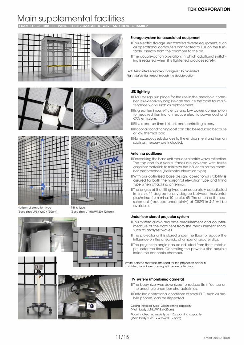
Left : Associated equipment storage is fully ascended.
Right : Safely tightened through the double action
Horizontal elevation type(Base size : L95 x W60 x T30cm)
White-colored materials are used for the projection panel in consideration of electromagnetic wave reflection.
Tilting type(Base size : L140 x W120 x T24cm)
Storage system for associated equipment This electric storage unit transfers diverse equipment, such as operational computers connected to EUT on the turn- table, directly from the chamber to the pit.
The double-action operation, in which additional switch- ing is required when it is tightened provides safety.
LED lighting EMC design is in place for the use in the anechoic cham- ber. Its extensively long life can reduce the costs for main- tenance works such as replacement.
Its great luminous efficiency and low power consumption for required illumination reduce electric power cost and CO2 emissions.
Blink response time is short, and controlling is easy.
Indoor air conditioning cost can also be reduced because of low thermal load.
No hazardous substances to the environment and human such as mercury are included.
Antenna positioner Downsizing the base unit reduces electric wave reflection. The top and four side surfaces are covered with ferrite absorber materials to minimize the influence on the cham- ber performance (Horizontal elevation type).
With our optimized base design, operational stability is assured for both the horizontal elevation type and tilting type when attaching antennas.
The angles of the tilting type can accurately be adjusted in units of 1 degree to any degree between horizontal plus/minus from minus10 to plus 45. The antenna tilt mea- surement (reduced uncertainty) of CISPR16-4-2 will be available.
Underfloor-stored projector system This system allows real time measurement and counter- measure of the data sent from the measurement room, such as analyzer waves.
The projector unit is stored under the floor to reduce the influence on the anechoic chamber characteristics.
The projection angle can be adjusted from the turntable pit under the floor. Controlling the power is also possible inside the anechoic chamber.
ITV system (monitoring camera) The body size was downsized to reduce its influence on the anechoic chamber characteristics.
Detailed operational conditions of small EUT, such as mo- bile phones, can be inspected.
Ceiling-installed type : 35x zooming capacity (Main body : L18 x W18 x H22cm)
Floor-installed movable type : 10x zooming capacity (Main body : L26.3 x W13.6 x H12.3cm)
12/ 15 emcrf_en/20150401
Main supplemental facilitiesEXAMPLES OF 10m TEST RANGE ELECTROMAGNETIC WAVE ANECHOIC CHAMBER
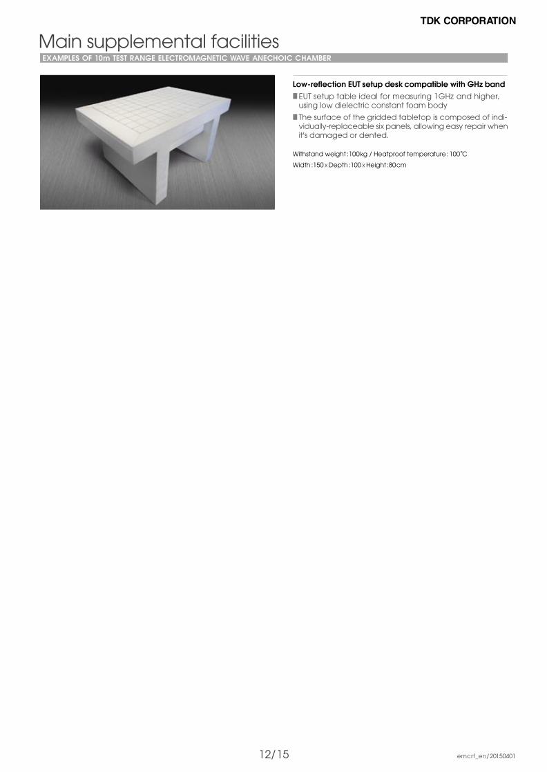
Low-reflection EUT setup desk compatible with GHz band EUT setup table ideal for measuring 1GHz and higher, using low dielectric constant foam body
The surface of the gridded tabletop is composed of indi- vidually-replaceable six panels, allowing easy repair when it's damaged or dented.
Withstand weight :100kg / Heatproof temperature : 100°C
Width :150 x Depth :100 x Height :80cm

TDK has accumulated an extensive history of achieve-ments in EMC automated measurement system for consumer devices, information communication de-vices, and automobiles in Europe, the United States, and Asia. Based on these achievements, we give suggestions for system arrangement best suited your requests. By combining TDK original hardware and automated measurement software such as system interface, an-tenna, and such, we realize efficient EMC measure-ment and superior measurement repeatability.
Automatic measurement system for EMI and EMSThe system is designed to provide high efficiency and accura-cy for radiation/conduction emission measurement test and radiation/conduction immunity test, whether it's done automati-cally, semi-automatically, or manually.We provide solutions meticulously responding to diverse needs from customers such as precautional measurement in the prod-uct development stage and EMC standard certification measurement and such.
EMC automated measurement system
TDK EMS Test System (Radiation immunity automatic measurement system example)
TDK EMI Test System (Radiation emission automatic measurement system example)
TDK RF
Antenna mast
Turntable
Master Control PanelTDK MCP-01
System InterfaceTDK SI-300
EMI Receiver
T/T & A/M Controller
EMI Rack
EMS Rack
TDK RF Solutions Inc.
Master Control PanelTDK MCP-01
TDK RF Solutions Inc.
TDK RF Solutions Inc.
Probe Interface
Signal Generator
FunctionGenerator
IEEE 488
IEEE 488
IEEE 488
IEEE 488
TDK RF
Bypass
Directional Coupler
Power Amplifier
Power Meter Power Sensor
PowerAmplifier
PreamplifierTDK PA-02
RF Switch ModuleTDK SI-300 LSM
TDK RF Solutions Inc.
1
C
2 1C
2
RemoteSwitch Module
TDK RSM-02
TDK RF Solutions Inc.
1
C
2 1
C
2
TDK RF Solutions Inc.
1
C
2
IEEE 488
IEEE 488
IEEE 488
IEEE 488
IEEE 488
System InterfaceTDK SI-300
TDK RF Solutions Inc.
Agilent
1
C
2
PSW1
1
C
2
PSW1
13 / 15 emcrf_en/20150401
14 / 15 emcrf_en/20150401
EMC automatic measurement software
EMC automated measurement system
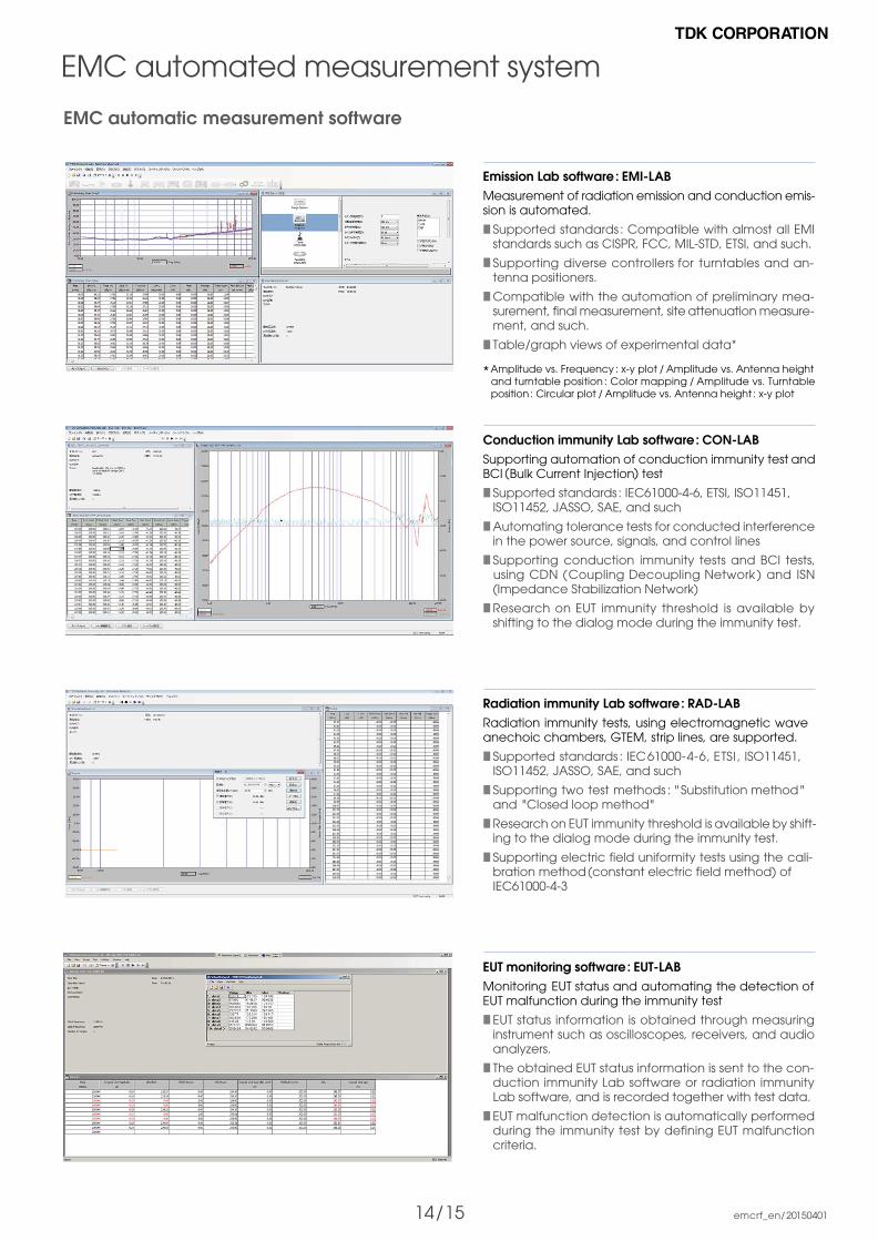
Emission Lab software : EMI-LABMeasurement of radiation emission and conduction emis- sion is automated.
Supported standards : Compatible with almost all EMI standards such as CISPR, FCC, MIL-STD, ETSI, and such.
Supporting diverse controllers for turntables and an- tenna positioners.
Compatible with the automation of preliminary mea- surement, final measurement, site attenuation measure- ment, and such.
Table/graph views of experimental data*
* Amplitude vs. Frequency : x-y plot / Amplitude vs. Antenna height and turntable position : Color mapping / Amplitude vs. Turntable position : Circular plot / Amplitude vs. Antenna height : x-y plot
Conduction immunity Lab software : CON-LABSupporting automation of conduction immunity test and BCI (Bulk Current Injection) test
Supported standards : IEC61000-4-6, ETSI, ISO11451, ISO11452, JASSO, SAE, and such
Automating tolerance tests for conducted interference in the power source, signals, and control lines
Supporting conduction immunity tests and BCI tests, using CDN (Coupling Decoupling Network ) and ISN (Impedance Stabilization Network)
Research on EUT immunity threshold is available by shifting to the dialog mode during the immunity test.
Radiation immunity Lab software : RAD-LABRadiation immunity tests, using electromagnetic wave anechoic chambers, GTEM, strip lines, are supported.
Supported standards : IEC61000-4-6, ETSI , ISO11451, ISO11452, JASSO, SAE, and such
Supporting two test methods : " Substitution method " and "Closed loop method"
Research on EUT immunity threshold is available by shift- ing to the dialog mode during the immunity test.
Supporting electric field uniformity tests using the cali- bration method (constant electric field method) of IEC61000-4-3
EUT monitoring software : EUT-LABMonitoring EUT status and automating the detection of EUT malfunction during the immunity test
EUT status information is obtained through measuring instrument such as oscilloscopes, receivers, and audio analyzers.
The obtained EUT status information is sent to the con- duction immunity Lab software or radiation immunity Lab software, and is recorded together with test data.
EUT malfunction detection is automatically performed during the immunity test by defining EUT malfunction criteria.

15/ 16 emcrf_en/20150401
EMC automated measurement system
Biconical HBA-2010
V-log periodic VLA-8001
Horn HRN-0106
20 to 100 MHz
80 to 1000 MHz
1 to 6 GHz
Antenna arrangement example
Antenna positioning system
Automated antenna switching system arrangement exampleFrom left to right: Biconical antenna, horn antenna, and V-log periodic dipole array
Control
Drivingmethod
Height control
Dimensions
Power source
Weight
Optical fiber cable
Azimuth rotation : 0.5RPM / Polarization sur- face-switching : Air driving 30PSI (2.1k/cm2)
Manual operation
60 x H200cm
Single phase AC100 - 270V
10kg
Specification example
Dual antenna positioning system : DAPSTwo reception antennas can automatically be switched with one mast.
Supported standards: CISPR12, SAE J551, 2004/104/EC
The software automated control allows the linking of the rotary angles of antenna and turntable to keep the right-angled corresponding positions of the antenna and car.
Antenna's polarization surface-switching can auto- matically be controlled.
Automatic antenna switching system for radiation immunity testsAutomated switching of three antennas optimizes EMS tests
Supported standards: ISO11451, ECE R10, SAE J551, 2004/104/EC
The software automated control allows the linking of the rotary angles of antenna and turntable to keep a constant distance between the antenna and car.
Antenna's polarization surface-switching can auto- matically be controlled.
16 / 16 emcrf_en/20150401
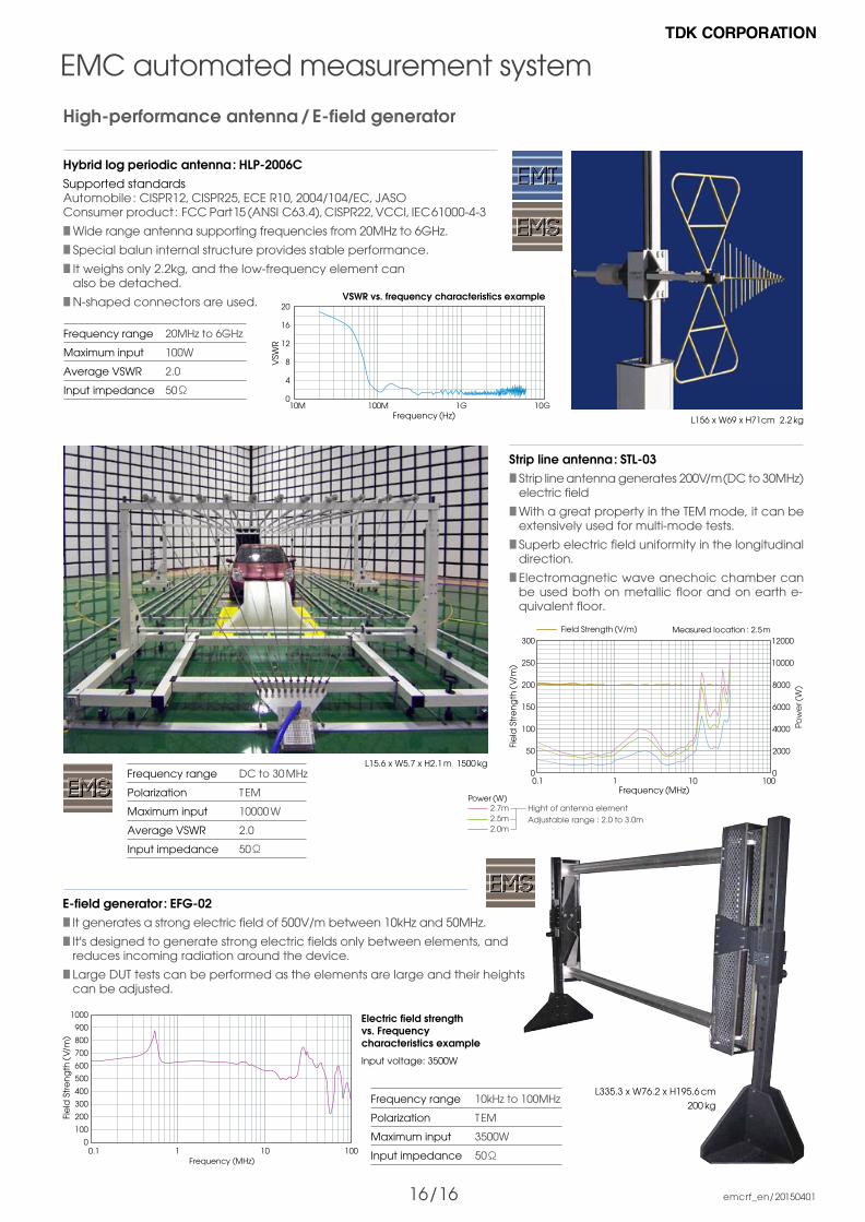
L156 x W69 x H71cm 2.2 kg
L335.3 x W76.2 x H195.6 cm
200 kg
0.1 1Frequency (MHz)
10 100
Fie
ld S
tre
ng
th (
V/m
)
300
250
200
150
100
50
0
8000
6000
4000
2000
0
Pow
er (
W)
12000
10000
Field Strength (V/m)
L15.6 x W5.7 x H2.1 m 1500 kg
Measured location : 2.5m
0.1 1Frequency (MHz)
10 100
Fie
ld S
tre
ng
th (
V/m
)
1000
900
800
700
600
500
400
300
200
100
0
Electric field strength vs. Frequency characteristics example
Input voltage: 3500W
VSWR vs. frequency characteristics example
10M 100MFrequency (Hz)
1G 10G
VSW
R
20
16
12
8
4
0
2.7mPower (W)
2.5m2.0m
Hight of antenna elementAdjustable range : 2.0 to 3.0m
EMC automated measurement system
High-performance antenna / E-field generator
Frequency range
Polarization
Maximum input
Average VSWR
Input impedance
DC to 30 MHz
TEM
10000 W
2.0
50
Frequency range
Polarization
Maximum input
Input impedance
10kHz to 100MHz
TEM
3500W
50
Frequency range
Maximum input
Average VSWR
Input impedance
20MHz to 6GHz
100W
2.0
50
Hybrid log periodic antenna : HLP-2006CSupported standards Automobile : CISPR12, CISPR25, ECE R10, 2004/104/EC, JASOConsumer product : FCC Part 15 (ANSI C63.4), CISPR22, VCCI, IEC 61000-4-3
Wide range antenna supporting frequencies from 20MHz to 6GHz.
Special balun internal structure provides stable performance.
It weighs only 2.2kg, and the low-frequency element can also be detached.
N-shaped connectors are used.
Strip line antenna : STL-03 Strip line antenna generates 200V/m(DC to 30MHz) electric field
With a great property in the TEM mode, it can be extensively used for multi-mode tests.
Superb electric field uniformity in the longitudinal direction.
Electromagnetic wave anechoic chamber can be used both on metallic floor and on earth e- quivalent floor.
E-field generator : EFG-02 It generates a strong electric field of 500V/m between 10kHz and 50MHz.
It's designed to generate strong electric fields only between elements, and reduces incoming radiation around the device.
Large DUT tests can be performed as the elements are large and their heights can be adjusted.