emc testing per cispr 12 and iso 11451-2 testing per cispr 12 and iso 11451-2: cispr 12, ... sae j...
TRANSCRIPT

EMC Testing per CISPR 12 and ISO 11451-2:
CISPR 12, ISO 11451-2 and Equivalent Standards

Outline
• The Standards• CISPR 12 site and chamber requirements• Antenna requirements for CISPR 12• ISO 11451-1 and –2: Chamber requirements• Recommended antennas and Amplifier
Power• Other Full Vehicle testing Standards• Conclusions

Standards
• Automotive Standards for full vehicle are mainly those from CISPR, SAE and ISO.
• OEMs have also their own internal standards.
• The following is a list of most of the Full Vehicle Standards.

CISPR Standards (full vehicle)
Spec Title Typ Equivalent Test set up Chamber needed
CISPR 12 Vehicles, boats, and internal combustion engine driven devices - radio disturbance characteristics -limits and methods of measurement
RE SAE J 551-2 a monopole is used for the range 150KHz to 30MHz only vertical polarization measurements are made, for 30MHz to 200MHz a biconical antenna is used, the log periodic is used for the range 200MHz-1000MHz or tunned dipoles can be used for the entire range. for 10m testing the antenna is located 3m over ground and it is not scanned, the antenna is 10meters from outer skin of vehicle and in line with engine mid point. Both sides of vehicle are tested. For 3m testing antenna is placed at 1.8m both polarizations are measured.
Chamber must be correlated to OATS, an NSA measurement showing a small deviation should demonstrate that.
CISPR25 Limits and methods of measurement of radio disturbance characteristics for the protection of receivers used on board vehicles
RI/RE
SAE J 551-4 and SAE J 1113-41
for the chamber testing procedure a monopole is used for the range 150KHz to 30MHz, for 30MHz to 200MHz a biconical antenna is used, the log periodic is used for the range 200MHz-1000MHz. For equipment testing a TEM cell can be used. Whole vehicle testing is trying to see how the radio or radios in the car are affected by the different systems in the vehicle, that is how the radio is affected by windshield wipers, to put an example
when an absorber lined chamber is used the absorption of the material has to be better than 6dB for the range 70MHz and up.

SAE Standards (full vehicle) ISAE J551- Title Typ Equivalent Test set up Chamber
needed
-1 Performance levels and Methods of measurement of EMC of vehicles and devices (60Hz-18GHz)
Definitions Definitions
-2 Test limits and methods of measurement of radio disturbance characteristics of vehicles, Motorboats, and spark-ignited Engine Driven Devices
RE CISPR12 See CISPR 12 See CISPR 12
-4 Test limits and methods of measurement of radio disturbance characteristics of vehicles and devices, broadband and narrowband, 150KHz to 1000MHz
RERI
CISPR 25 See CISPR 25 See CISPR 25
-5 Performance levels and methods of measurement of magnetic and electric field strength from electric vehicles, 9kHz to 30MHz
Specifies limits for electric vehicles

SAE Standards (full vehicle) IISAE J551- Title Typ Equivalent Test set up Chamber
needed
-11 Vehicle Electromagnetic immunity-Off vehicle source
RI ISO 11451-2 No absorbent material between antenna and EUT. Antenna is to be place at least 2m from the vehicle engine's center point the uniformity plane is HORIZONTAL and it is a 1.5 diameter circle where the field for frequencies above 200MHz is between +-3dB for 80% of the frequencies
shielded anechoic chamber.
-12 Vehicle Electromagnetic Immunity-On board transmitter simulation
Self RI
ISO 11451-3 a shielded room that will meet the SAE j551-1 and -2 will do
-13 Vehicle Electromagnetic Immunity-Bulk Current injection
CI ISO 11451-4 a shielded room will do, no absorber is necessary but test can be performed in a shielded enclosure with absorber
-15 Vehicle Electromagnetic Immunity-Electrostatic Discharge
ESD ISO-10605 Shielded room
-17 Vehicle Electromagnetic Immunity-Power line magnetic fields
RI Large area for vehicle and field generating coils
Shielded enclosure recomended
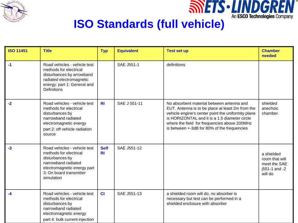
ISO Standards (full vehicle)
ISO 11451 Title Typ Equivalent Test set up Chamber needed
-1 Road vehicles - vehicle test methods for electrical disturbances by arrowband radiated electromagnetic energy: part 1: General and Definitions
SAE J551-1 definitions
-2 Road vehicles - vehicle test methods for electrical disturbances by narrowband radiated electromagnetic energypart 2: off vehicle radiation source
RI SAE J 551-11 No absorbent material between antenna and EUT. Antenna is to be place at least 2m from the vehicle engine's center point the uniformity plane is HORIZONTAL and it is a 1.5 diameter circle where the field for frequencies above 200MHz is between +-3dB for 80% of the frequencies
shielded anechoic chamber.
-3 Road vehicles - vehicle test methods for electrical disturbances by narrowband radiated electromagnetic energy part 3: On board transmitter simulation
Self RI
SAE J551-12a shielded room that will meet the SAE j551-1 and -2 will do
-4 Road vehicles - vehicle test methods for electrical disturbances by narrowband radiated electromagnetic energypart 4: bulk current injection
CI SAE J551-13 a shielded room will do, no absorber is necessary but test can be performed in a shielded enclosure with absorber

2004/144 EC Standard (full vehicle)
2004/144 EC Title Typ Equivalent Test set up Chamber needed
Annex IAnnex II AAnnex II B
Requirements met by vehicles and electrical/electronic sub-assemblies fitted to a vehicle
SAE J551-1 definitions
Annex IV Method of measurement of radiated broadband emissions from vehicles
RE CISPR 12 a monopole is used for the range 150KHz to 30MHz only vertical polarization measurements are made, for 30MHz to 200MHz a biconical antenna is used, the log periodic is used for the range 200MHz-1000MHz or tunned dipoles can be used for the entire range. for 10m testing the antenna is located 3m over ground and it is not scanned, the antenna is 10meters from outer skin of vehicle and in line with engine mid point. Both sides of vehicle are tested. For 3m testing antenna is placed at 1.8m both polarizations are measured.
Chamber must be correlated to OATS, an NSA measurement showing a small deviation should demonstrate that.
Annex V Method of measurement of radiated narrowband emissions from vehicles
Annex VI Method of testing for immunity of vehicles to electromagnetic radiation
RI antenna is placed no less than 1.5m above the ground and no less than 2 meters from the center of the engine field uniformity requirement is that points on a horizontal line of 1m in length perpendicular to the antenna line of sight must be within 6dB
Absorber lined chamber

Regarding Standards
• As mentioned before there are a lot of Standard Documents that were not on the above list. However, a lot of the documents that are not mentioned are based on international documents. Of these international standards CISPR 12 and ISO 11451 are the critical ones.

CISPR 12Vehicles, boats, and internal combustionengine driven devices –Radio disturbance characteristics –Limits and methods of measurement for the protection of receivers except those installed in the vehicle/boat/device itself or in adjacent vehicles/boats/devices

CISPR 12Radio disturbance characteristics for theprotection of receivers used from emissions fromvehicles, boats, and on devices …

CISPR 12• So CISPR 12 deals with how much do electric
and electronic systems affect outside receivers from emissions from systems aboard:– Automobiles powered by internal combustion
engines or electric motors– Boats (up to 15m) powered by internal combustion
engines or electric motors– Devices powered by internal combustion engines
but not for the transport of people.(I.e. compressors, chainsaws, garden maintenance equipment, etc)

CISPR 12• As with any other emissions standard
we look at measurements at 10m (3m being allowed and limits being raised by 10dB)
• There are limits for Broadband noise and narrowband noise

CISPR 12• Limits for
broadband emissions.
• Background noise should be 6dB below the limits (more on that later) and for 3m levels should be 10dB higher

CISPR 12• Limits for
narrow band emissions.
• Background noise should be 6dB below the limits (more on that later) and for 3m levels should be 10dB higher

CISPR 12• Regarding the
test site, the CISPR 12 Standard defines the oats as the recommended site.
• The OATS must follow the requisites stated in CISPR 16

OATS layout
10m (3m)
3m (1.8m)
15mEquipment or huts only beyond this point
30m radius of clear area

measurement layout
10m (3m)
3m (1.8m)
3m (1.8m)
10m (3m)Both sides of the vehicleHave to be measured. The antennas are to be in line with the vehicle under test.

Measurement Layout 19
• The 10m emission testing locates the antenna 10m from the outer shell of the vehicle
• The antenna is not scan but located at 3m height. (For 3m testing the antenna is located at 1.8meters.
• Both sides of the vehicle and both polarizations are tested
10 meters
LPDA
BICONICAL
HORN
10 meters
10 meters

Automotive Testing: A Short Introduction 20
• The antenna is to be in line with the middle point of the engine compartment.
• A two antenna position site and the addition of a turntable makes the test much easier
• There is no need to reposition the vehicle to test the other side.
Plane of longitudinal symmetry
10 meters
mid point of engine compartment
Antenna in line withmid point of engine compartment
10 meters
The antenna not in use is setAt a different polarization toreduce coupling between antennas
10 meters

CISPR 12 EUT req.
• Internal combustion engine:– Engine Idle:
• 2500RPM 1cyl• 1500RPM 2 or more cyl
• Electric Propulsion motors– Vehicle running:
• 40km/h or max vehicle speed if less.

CISPR12: Antennas
• Antennas are a key requirement in CISPR 12. The standard bases its choice of antennas on the CISPR 16 Standard
Frequency range Type
30Hz-50MHz Active monopole rod
30-300MHz Biconical
200-2000MHz Log periodic
1GHz-18 GHz Dual ridge guidehorns
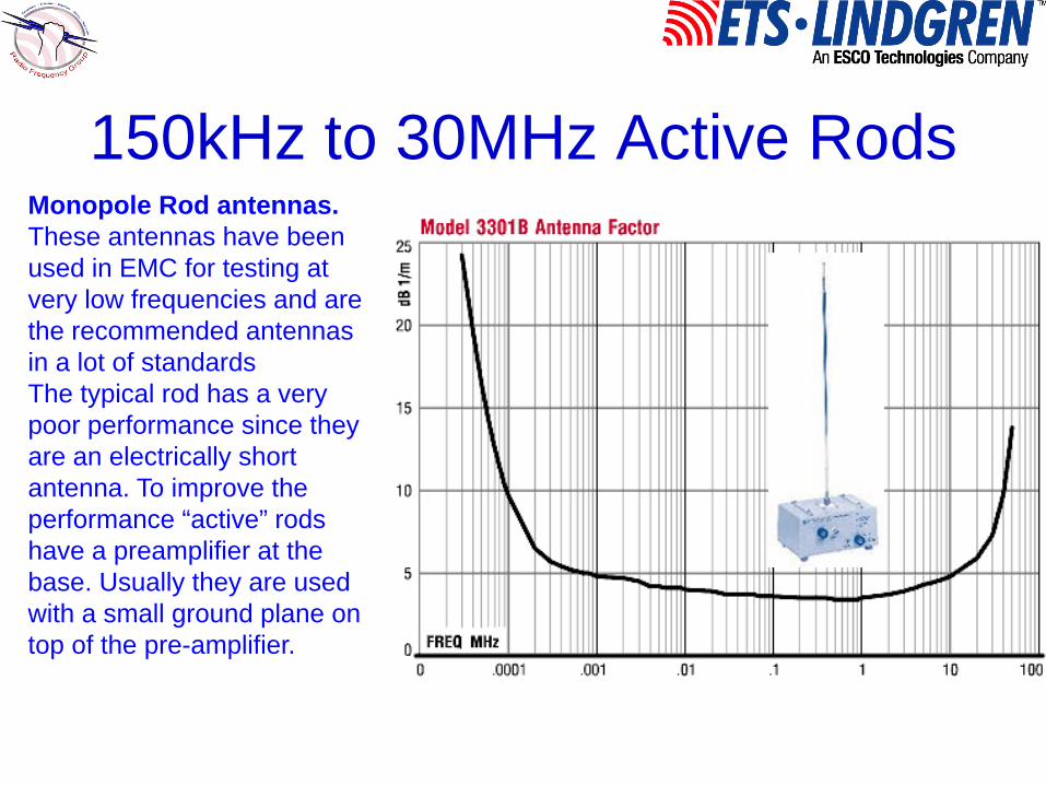
150kHz to 30MHz Active RodsMonopole Rod antennas.These antennas have been used in EMC for testing at very low frequencies and are the recommended antennas in a lot of standards The typical rod has a very poor performance since they are an electrically short antenna. To improve the performance “active” rods have a preamplifier at the base. Usually they are used with a small ground plane on top of the pre-amplifier.

30MHz to 200MHz biconicalsBiconical Antennas.These antennas have been used in EMC for testing at low frequencies and are the recommended antennas in a lot of standards The typical biconical antenna usually has a range of 20 to 300MHz, However, it is recommended that they are used from 30MHz to 200Mhz where they offer their best performance compared with other antennas.

200MHz to 2000MHz log periodicsLog Periodic antennas.200MHz to 1GHz it isrecommended that a logperiodic antenna be used.Log periodic antennashave a typical range of200 to 2000MHz or3000MHz depending onthe manufacturer.

Ridge horns 1GHz to 18GHzDual Ridge Horns.There are however, newermodels in the market thatcorrect the patternproblems of the traditionaldual ridge horns. The newdual ridge horns areantennas with improvedpattern behavior above10GHz. This translates into a more constantantenna factor and gain.

Alternative Sites
• Anechoic Chamber:– A shielded absorber lined enclosure can be
used provided that correlation with OATS can be shown
– In my view, doing the NSA measurement of the Chamber if the results fall within the limits of the CISPR 16 requirements the Chamber is good for CISPR 12 testing
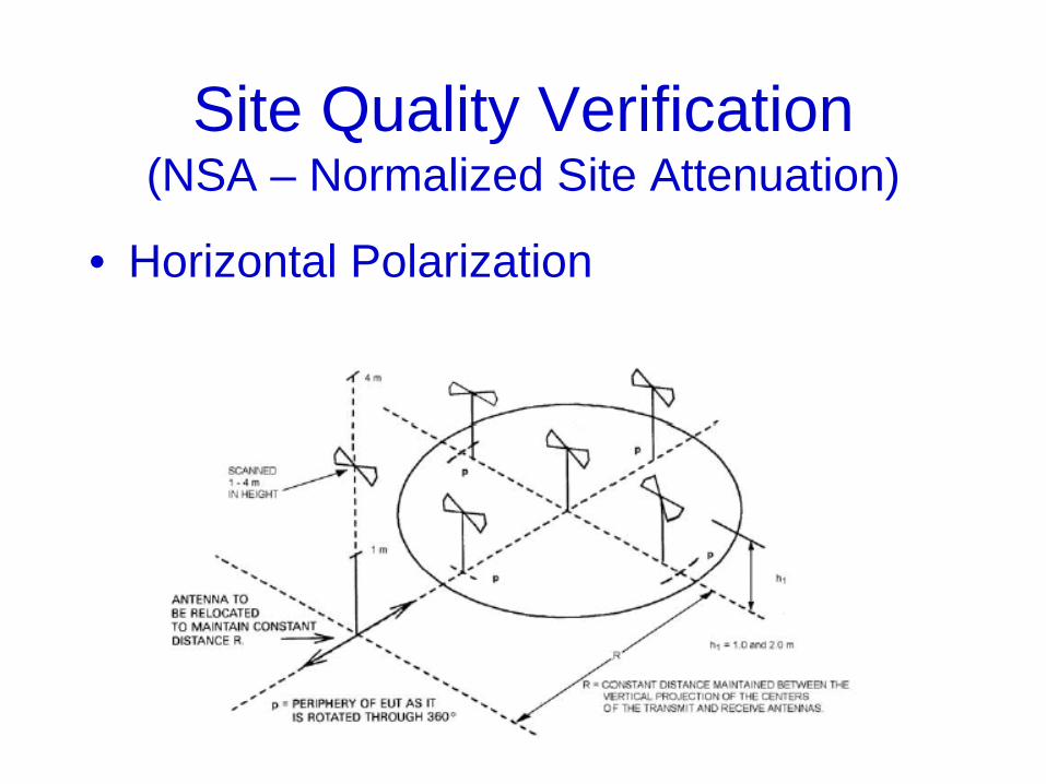
Site Quality Verification (NSA – Normalized Site Attenuation)
• Horizontal Polarization

Site Quality Verification (NSA – Normalized Site Attenuation)
• Vertical Polarization
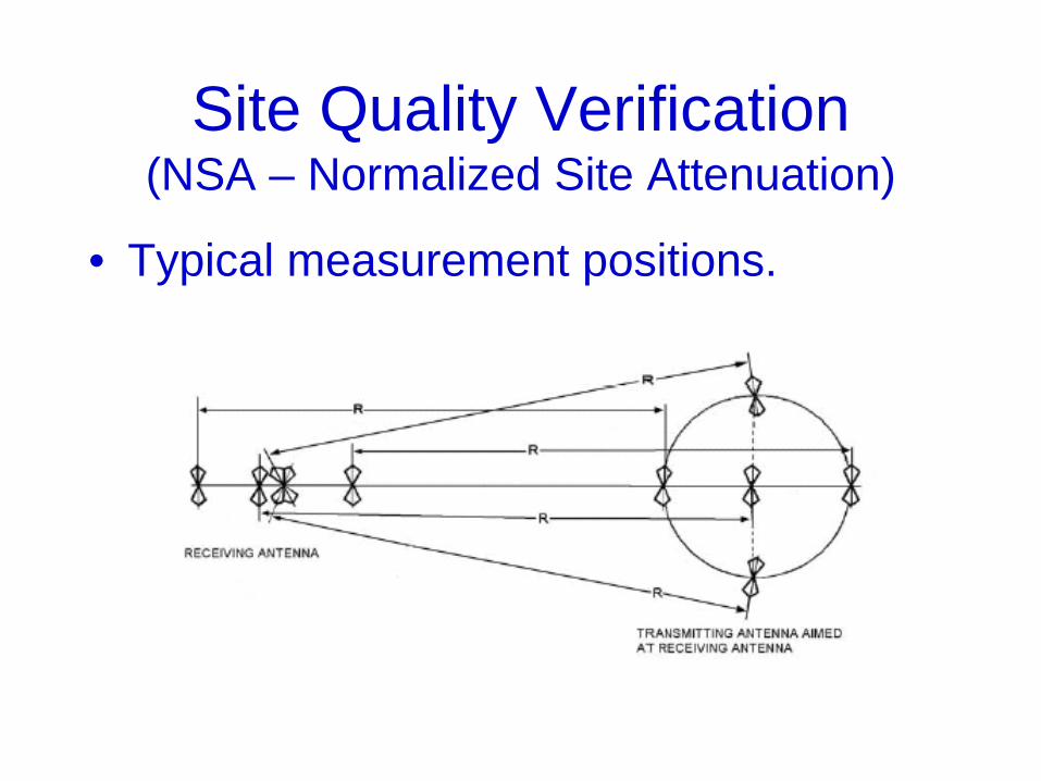
Site Quality Verification (NSA – Normalized Site Attenuation)
• Typical measurement positions.
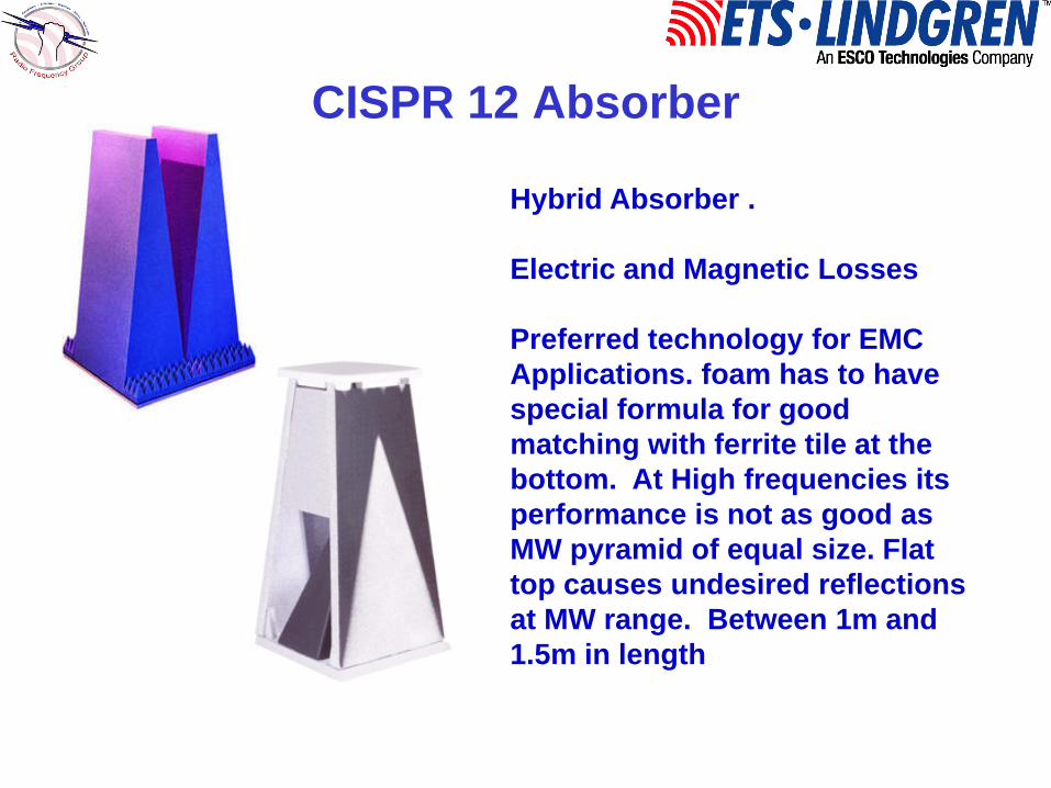
CISPR 12 Absorber
Hybrid Absorber .
Electric and Magnetic Losses
Preferred technology for EMCApplications. foam has to have special formula for good matching with ferrite tile at the bottom. At High frequencies its performance is not as good as MW pyramid of equal size. Flat top causes undesired reflections at MW range. Between 1m and 1.5m in length

Honda R&D America Raymond, Ohio

GM Proving Grounds Milford, Michigan

CISPR 12
Microwave Pyramidal absorber.EMC and EHP series
Electric Losses
Preferred technology for High frequenciesIt can be used for low frequencies if size (length) is increased, for CISPR 12 chambers minimum 1.8m and also use of curvilinear pyramids

Commercial EMC/Automotive EMC and Antenna/Satellite Chamber at LIT/INPE São Jose dos Campos, SP, Brazil

Typical EMC 10m range Chambers
model SizeFt (m)
absorber NSA FU
FACT 10 –3.0 Std 59,30,22 (18,9.2,6.6)
PS-1250 all walls and ceiling, RI patch of PS 600
±4.0dB 0 to +6dB 75%
FACT 10 – 3.0 Std +
63,38,28 (19,11.5,8.5)
PS-1250 9 rows walls, ceiling, RI patch of PS 600
±3.5dB 0 to +6dB 75%
FACT 10 –3.0 premium
63,38,28 (19,11.5,8.5)
FS-1500 9 rows on walls, ceiling, RI patch FS-400
±3.0dB 0 to +6dB 75%
FACT 10 –4.0 Std 65,36,22(20,11,6.6)
PS-1250 all walls and ceiling, RI patch of PS 600
±4.0dB 0 to +6dB 75%
FACT 10 – 4.0 Std +
65,40,28(20, 12, 8.5)
PS-1250 9 rows walls, ceiling, RI patch of PS 600
±3.5dB 0 to +6dB 75%
FACT 10 –4.0 premium
65,40,28(20,12,8.5)
FS-1500 9 rows on walls, ceiling, RI patch FS-400
±3.0dB 0 to +6dB 75%
FACT 10-6.0 Std + 71,43,28(22,13,8.5)
PS-1250 9 rows walls, ceiling, RI patch of PS 600
±3.5dB 0 to +6dB 75%

Special features for automotive
• Dynamometer Turn Table. Although for emissions the vehicle just needs to idle.
• Exhaust system• Fire Protection systems• QZ may be as large as 9m making
chamber larger• Chamber supported EH generators• Large level entry door
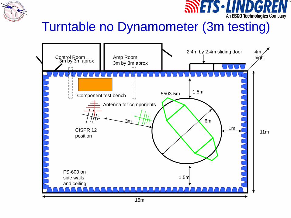
3m 6m
1.5m
1.5m
1m
Control Room3m by 3m aprox
Amp Room3m by 3m aprox
Component test bench
2.4m by 2.4m sliding door
Antenna for components
CISPR 12 position
15m
11m
5503-5m
4mhigh
FS-600 on side walls and ceiling
Turntable no Dynamometer (3m testing)

Dynamometerfor vehicles 6m by 2m
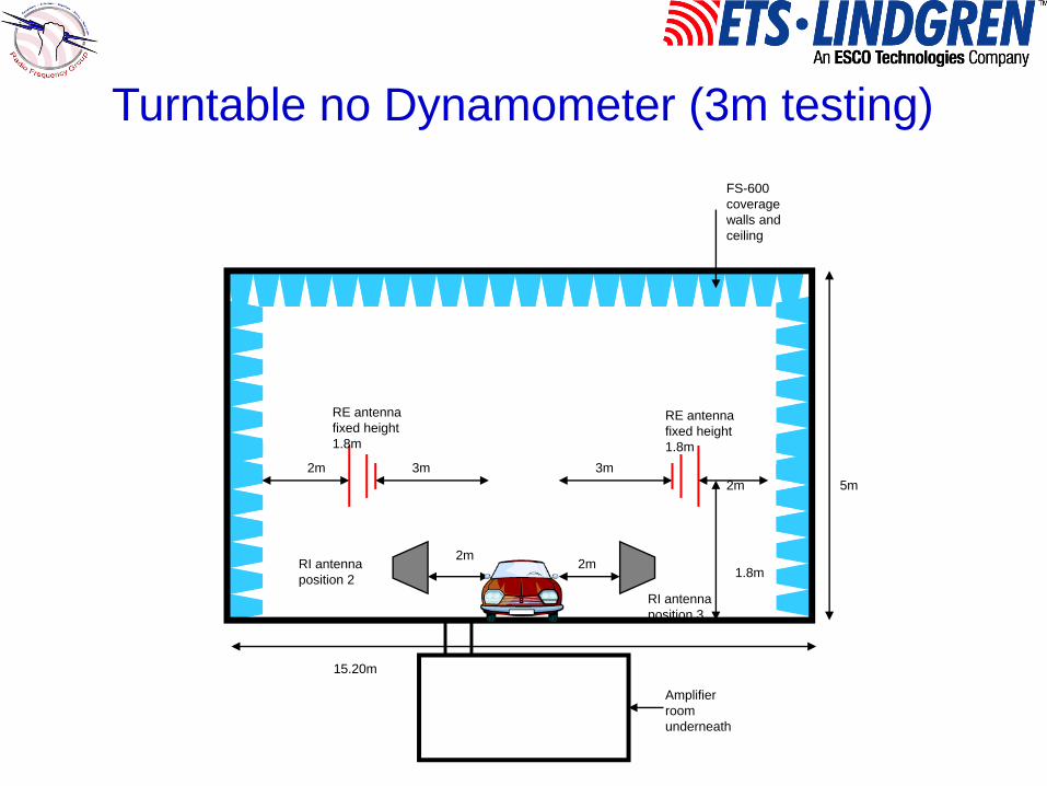
3m 3m
RE antenna fixed height 1.8m
RE antenna fixed height 1.8m
Amplifier room underneath
RI antennaPosition 1
RI antenna position 3
RI antenna position 2
2m
2m2m
2m
2m
2m
2m
15.20m
15.20m
Control room
2m diameter QZ
FS-600 coverage walls and ceiling
Dynamometer no Turntable (3m testing)
3m 3m
RE antenna fixed height 1.8m
RE antenna fixed height 1.8m
Amplifier room underneath
RI antenna position 3
RI antenna position 2
2m2m
2m2m
1.8m
5m
15.20m
FS-600 coverage walls and ceiling
Turntable no Dynamometer (3m testing)

Vehicle immunity
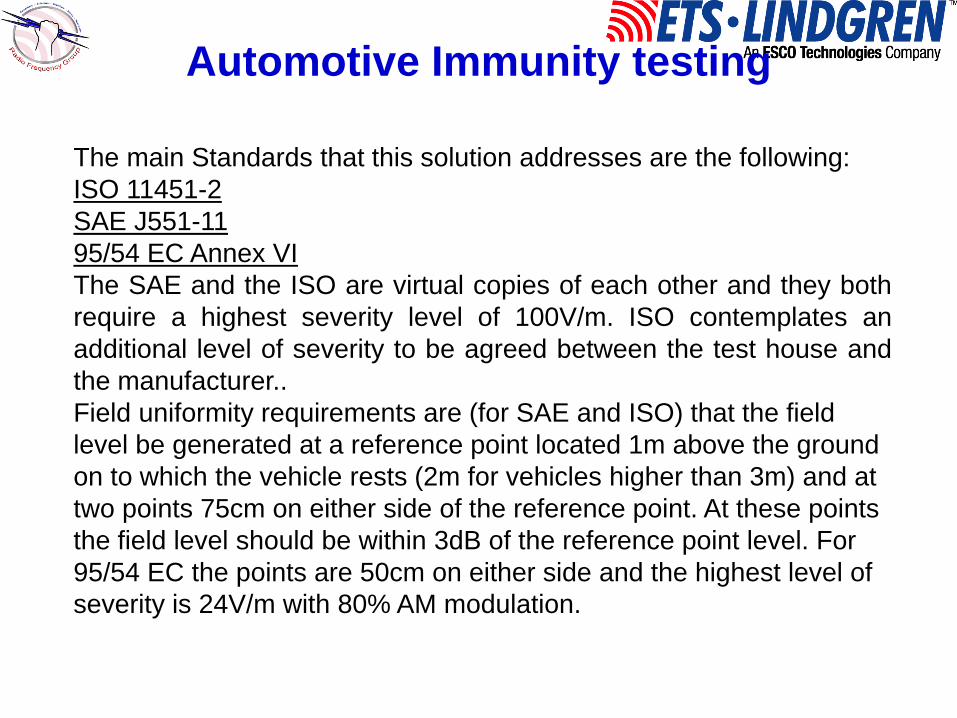
Automotive Immunity testing
The main Standards that this solution addresses are the following:ISO 11451-2SAE J551-1195/54 EC Annex VIThe SAE and the ISO are virtual copies of each other and they bothrequire a highest severity level of 100V/m. ISO contemplates anadditional level of severity to be agreed between the test house andthe manufacturer..Field uniformity requirements are (for SAE and ISO) that the field level be generated at a reference point located 1m above the ground on to which the vehicle rests (2m for vehicles higher than 3m) and at two points 75cm on either side of the reference point. At these points the field level should be within 3dB of the reference point level. For 95/54 EC the points are 50cm on either side and the highest level of severity is 24V/m with 80% AM modulation.

Automotive EMC Immunity
• 100V/m highest severity level (200v/m contemplated in the ISO standard
• Field Uniformity RequirementsReference point
1m, 2m for vehicles over 3m
0.5m 0.5m
SAEJ551-11ISO 11451-2200MHz and above

The reference point position on the vehicle corresponds to the pointwhere the windshield and the hood of the car meet. Or the front axel,which ever is farther away from the antenna.For rear-engined vehicles the vehicle will be tested with the rearfacing the antenna and the reference point at the rear axel.
Reference point falls on this plane
Automotive EMC Immunity
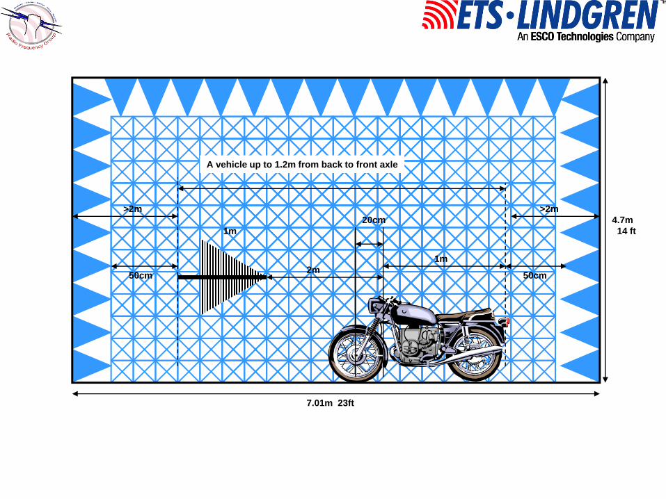
7.01m 23ft
4.7m14 ft
>2m
50cm 50cm
>2m
A vehicle up to 1.2m from back to front axle
20cm
2m1m
1m

Field Generation
The key to automotive immunity is the generation of high fields. The proper selection of the antenna is key to lowering the amplifier requirements.
The next Slides deal with recommendations of the most suitable antennas for ISO 11451-2 and equivalent standards.

Recommended Antennas
• 100kHz to 30MHz E-H generator• 30MHz to 100MHz Biconical• 100MHz to 1000MHz Dual Ridge Horn• 1000MHz to 18000MHz Octave Gain
horns
E-H Field Generators
• Transverse Electromagnetic Mode Transmission lines.
• Field concentrated between elements and ground.
• No radiation into the chamber unless separation between the elements is more than ½ a wavelength
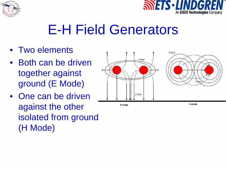
E-H Field Generators• Two elements• Both can be driven
together against ground (E Mode)
• One can be driven against the other isolated from ground (H Mode)

E-H Field Generators
To test the performance the field is measured at one point 1m over the ground and 1/3 the length of the elements from the transition region.This places the test point roughly at the location of the reference point described on the standards

E-H Field Generators
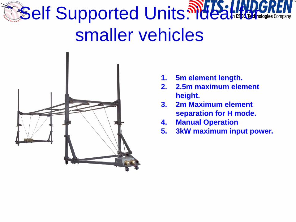
Self Supported Units: ideal for smaller vehicles
1. 5m element length.2. 2.5m maximum element
height.3. 2m Maximum element
separation for H mode.4. Manual Operation5. 3kW maximum input power.

Self supported units
0.1 1 10100
1000
100005503-5m power requirements for 100v/m
3kW input power limit H-mode probe at 1.5 over ground E-mode 1.5m probe at 1m over ground E-mode 2.0m probe at 1m over ground E-mode 2.5m probe at 1m over ground
Inpu
t Pow
er (w
)
frequency (MHz)
with its limited input power (3kW) can only meet 100v/m requirements. Also it is manually operated and requires at least 4 people to set up. It is intended as a lower cost alternative for small vehicle testing

Automated chamber supported Units
1. Variable element length (as customer required)
2. Variable pneumatic element separation for H mode.
3. Variable height motor driven
4. 10kW maximum input power.

Chamber supported

Chamber supported

Chamber supported

Large bicons(30MHz-100MHz)
fixed height positioner with pneumatic assisted polarization.

antenna at INPE chamber

antenna at INPE chamber

Ridge horn (100MHz-1000MHz)
fixed height positioner with pneumatic assisted polarization and manual boresight adjustment (±10 degrees)

ridge antenna in INPE chamber

Field levels for 1kW input

Above 1GHz (octave horns)
Gains of 15.5 to 17dBiHowever narrow beams so scanning across EUT may be required.
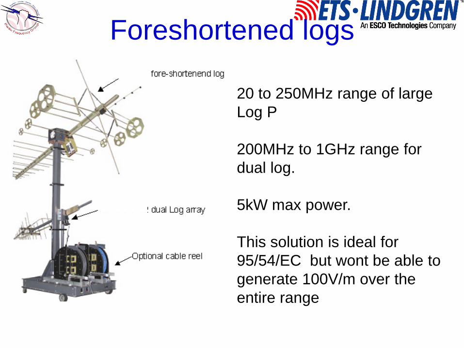
Foreshortened logs
20 to 250MHz range of large Log P
200MHz to 1GHz range for dual log.
5kW max power.
This solution is ideal for 95/54/EC but wont be able to generate 100V/m over the entire range
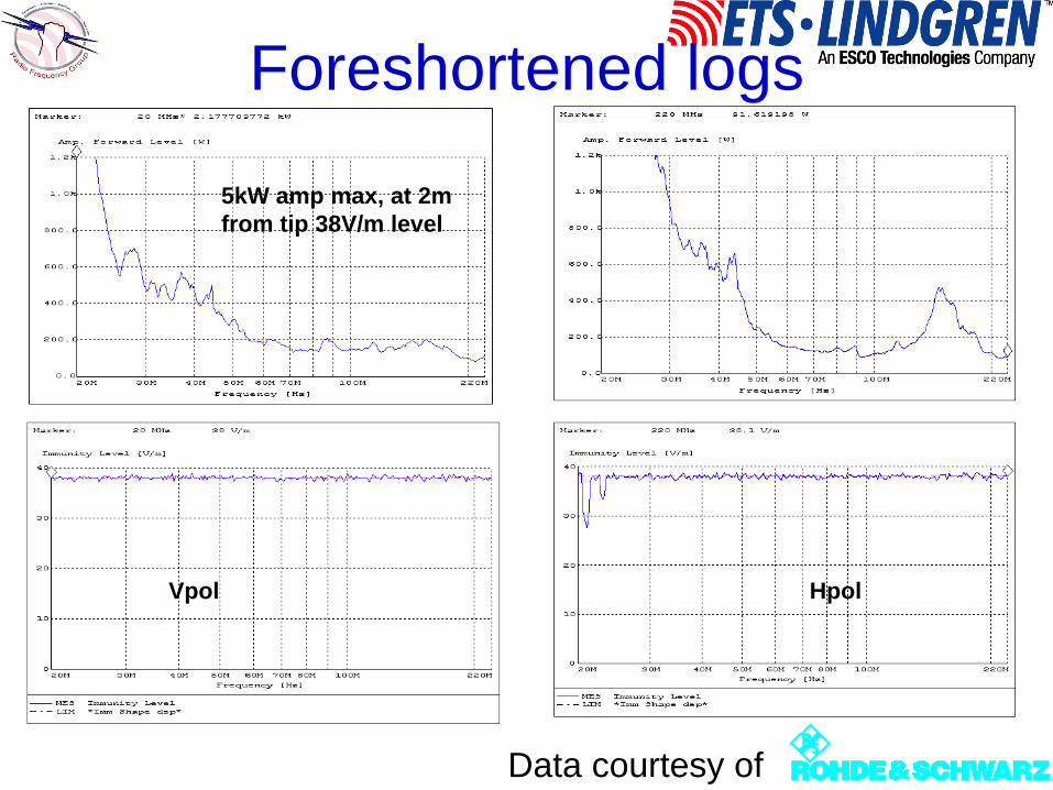
Foreshortened logs
Data courtesy of
Vpol Hpol
5kW amp max, at 2m from tip 38V/m level

Overview

Conclusions
• Hopefully you have gain knowledge on the chamber and antenna requirements for full vehicle testing
• These are expensive large facilities that only manufacturers could afford
• There may be a potential market for private EMC labs to set up full vehicle labs to take care of the increasing demand for full vehicle testing in Asia.