eme 185 - flexible assembly systems inc. | torque and ... · web viewtable 1: carbon steel, aisi...
TRANSCRIPT

EME 185“Preliminary Machine Architecture”
Chris AdamsAlex BakosRyan FlavellLeo Gomez
Drum Brake Manipulator

Definition of Task:
A mechanical manipulator arm, utilizing electric power, will be designed for a pick and place operation. The manipulator will pick up the drum brake from the gravity roller conveyor, orientate, align and place it on the axle for a worker to bolt in place. It is intended to be operated by a single operator with the total time of assembly to be approximately one and a half minutes. Ultimately, the aim of this manipulator arm is to improve ergonomics of the process, and increase productivity and safety in the assembly of the brake drums to the axle.
Design Strategy:
After dividing the manipulator arm into four subsystems (clamping, lifting, tilting, and rotating) and selecting the best idea from each subsystem; the group’s focus turned to how to effectively and efficiently integrate the four subsystems together. Included in Appendix A is the preliminary design for the manipulator arm, which shows the four specific subsystems and the interfacing subsystems together. Also, included in this report are the sketches of each subsystem interface.
The next step in this project will be to present this design to our industry sponsor, Flexible Assembly, and listen to their feedback with regards to our future steps for this project.
Subsystems and their interfaces:
Lifting:
The primary responsibility of the lifting subsystem is to lift and lower the manipulator arm carrying the brake drum to the axle. It must reliably maintain this height while traveling to the axle and bring it level to the height of the axle. Another aspect that was considered with the lifter is that while lifting and transporting, the subsystem must be rigid to prevent against swaying while traveling.
The vertical movement mechanism will be made of two steel square tubes of slightly different sizes mounted vertically from the overhead rail system. The smaller of the two tubes will move inside the larger allowing for the vertical movement of the drum brake. This lifting will be achieved through dual electric powered linear actuators. (Appendix C) This lifter will have the range of motion from the gravity roller conveyor (24 inches off the ground) to the height of the axel assembly (44 inches off the ground), a span of about 20 inches. The linear actuators that have been specified allow for 30 inches of travel and provide a lifting force of 400lb a piece.
Interface with various subsystems: From the 7500 Knightbridge to the rigid column, steel tubing.
The vertical movement mechanism needs to integrate with two other systems, one to the top and one to the bottom. (Appendix D) The top system is the rail system connected to the 7500 Knightbridge (Figure 1) and the bottom system is the tilting hinge connected to the clamp (Figure 2). To mate with the rail system there are two possible methods. One is a direct MIG weld to a selected rail car and the second is to bolt the vertical movement mechanism to the rail car.
While the MIG welds would provide a stronger link between the two systems, we have decided to go with two bolts in double sheer to the rail car. This is because bolts do not require specialist to assemble and can be put together without having to take welding safety precautions required in a fully operational plant. Secondly, welding requires much more time to assemble and dissemble which could

be a major issue if our machine is no longer required for manufacturing or needs to be disassembled for maintenance. Two bolts were chosen to keep the vertical movement mechanism as ridged as possible, as specified by the buyer.
To mate the bottom of the rigid column and the tilting hinge, a special bracket is to be welded onto the bottom of the lower steel tube that will connect to the hinge with regular hardware. Again, bolts were selected for this interface because they allow for quick replacement and the ability to assemble and disassemble the subsystems quickly.
Figure 1: Top Piece Figure 2: Bottom Piece

Tilting: The tilting subsystem is actually the interface from the lifting to the clamping.
The drum brake assembly must be able to rotated 90 degrees with the pumpkin oriented towards the inside of the axle. When the assembly is tilted, it must remain in a level position for the brake assembly to fit flush to the flange on the axle.
Several subsystems were considered to tilt the drum brake 90 degrees, and all of them will probably work out fine. The best idea which we have for tilting comes from using a hinge above the clamp and after clamping the shaft, when the drum brake assembly is pulled up, it will tilt as well and almost become level on its own. The only decision at this point becomes how to lock the assembly at the level position. Two strong ideas are to either have bolt go through the hinge to lock it in place once 90 degrees is reached or to attach a winch to the outside of the clamp to pull it to a straight position. Further tests will need to be made to determine which one works more efficiently.

Clamping: From the rigid support column to the clamp.
The clamping subsystem briefly is the pipe clamp from Caldwell Inc. (Appendix B)
The clamping interface has the responsibility to integrate the clamp to the rotating, lifting and swiveling subsystems, the clamp will use a heavy duty bolt fastening it to square tubing made out of Carbon Steel, AISI 1060 (Normalized) which is typically used for general construction; general mechanical engineering applications as well as automotive, tools and springs.
Density [kg/m^3] 7.8e3 - 7.9e3Price [USD/kg] .0857 - .943
Mechanical PropertiesYoung's Modulus 208 - 216 [Gpa]Shear Modulus 80 - 85 [Gpa]Bulk Modulus 161 - 176 [Gpa]
Poisson's Ratio 0.285 - 0.295 [Gpa]Yield Strength 375- 465 [Mpa]
Tensile Strength 695- 855 [Mpa]Compressive Strength 375 - 465 [Mpa]
Flexural Strength 375 - 465 [Mpa]Fatigue Strength at 10^7 Cycles 331 - 384 [Mpa]Maximum Service Temperature 305 - 345[C]Minimum Service Temperature -53 - -23 [C]
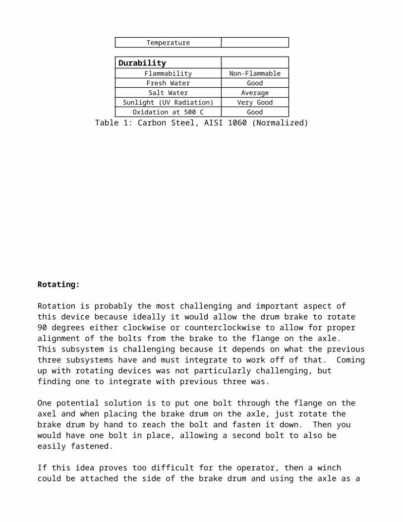
DurabilityFlammability Non-FlammableFresh Water GoodSalt Water Average
Sunlight (UV Radiation) Very GoodOxidation at 500 C Good
Table 1: Carbon Steel, AISI 1060 (Normalized)
Rotating:

Rotation is probably the most challenging and important aspect of this device because ideally it would allow the drum brake to rotate 90 degrees either clockwise or counterclockwise to allow for proper alignment of the bolts from the brake to the flange on the axle. This subsystem is challenging because it depends on what the previous three subsystems have and must integrate to work off of that. Coming up with rotating devices was not particularly challenging, but finding one to integrate with previous three was.
One potential solution is to put one bolt through the flange on the axel and when placing the brake drum on the axle, just rotate the brake drum by hand to reach the bolt and fasten it down. Then you would have one bolt in place, allowing a second bolt to also be easily fastened.
If this idea proves too difficult for the operator, then a winch could be attached the side of the brake drum and using the axle as a pivot point, rotate the brake drum about the axle by pulling the winch up one side or the other. This would satisfy the condition of allowing 90 degrees rotation is either direction.
Rotating Interface:
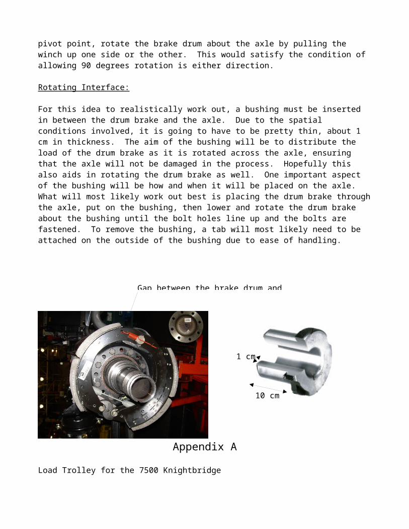
For this idea to realistically work out, a bushing must be inserted in between the drum brake and the axle. Due to the spatial conditions involved, it is going to have to be pretty thin, about 1 cm in thickness. The aim of the bushing will be to distribute the load of the drum brake as it is rotated across the axle, ensuring that the axle will not be damaged in the process. Hopefully this also aids in rotating the drum brake as well. One important aspect of the bushing will be how and when it will be placed on the axle. What will most likely work out best is placing the drum brake through the axle, put on the bushing, then lower and rotate the drum brake about the bushing until the bolt holes line up and the bolts are fastened. To remove the bushing, a tab will most likely need to be attached on the outside of the bushing due to ease of handling.
Appendix A
1 cm
10 cm
Gap between the brake drum and axle (1.2
Load Trolley for the 7500 Knightbridge
Lifting Interface: Trolley to Linear Actuator
Linear Actuator plus tubing (x2)
Lifting Interface: Tubing to Tilter
Tilting / Clamping Interface:
Clamp:
Appendix B
Clamping Subsystem:
The responsibility of the clamping subsystem is to clamp the manipulator arm to the brake drum. The two main requirements of this subsystem are to reliably and properly secure and hold the brake drum while traveling and ensure that the clamp does not interfere with bolting the assembly to the axle. While keeping these two requirements in mind, how and where the manipulator arm clamps to the brake drum will also influence the designs of the other four systems.
After studying many different clamping designs, the group decided on clamping to the shaft on the outside of the brake drum. This shaft has a diameter of 6 cm and a height of about 6 inches. We would preferably want to clamp to the bottom part of this shaft if possible for strength and stability reasons because we will later be tilting the device about this shaft.
The product to the left is currently our number one design choice. This design comes from Caldwell Group, Inc, a designer and manufacturer of lifting products. The product to the left was originally designed to lift pipes, but we feel that the shaft of our brake drum strongly correlates to pipes and that this device will not have any problems clamping and securing the brake drum. The dimensions for the pipe clamp which would best suit the brake drum are shown below.
Dimensions [in]A B C D E F Weight [lbs] Capacity [lbs]11 17 11 0.50 1.31 1.88 14 1000


Appendix C
400 Pound Force, 30” Stroke, Linear Actuator
http://www.firgelliauto.com/product_info.php?cPath=93&products_id=105

Appendix D
Dimensions of the Top Lifting Interface Bracket

Dimensions of the Bottom Lifting Interface Bracket

Appendix E

Appendix F
CPM-PERT Chart