emerald split system - marine air conditioning · emerald split system installation, operation...
TRANSCRIPT

COPYRIGHT © 2007-2011 Dometic Marine. All Rights Reserved.
No part of this publication may be reproduced, translated, stored in a retrieval system, or transmitted in any form or by any means electronic, mechanical, photocopying, recording or otherwise without prior written consent by Dometic Marine. Every precaution has been taken in the preparation of this manual to ensure its accuracy. However, Dometic Marine assumes no responsibility for errors and omission. Neither is any liability assumed for damages resulting from the use of this product and information contained herein.
Emerald Split SystemInstallation, Operation & Maintenance Manual
Emerald Evaporator Emerald Condenser
Dometic MarineRev. 20110209L-2805 EnglishP/N: 336021
L-2805 ENGLISH
Table of Contents
INTRODUCTION . . . . . . . . . . . . . . . . . . . . . . . . . . . . . . . 1READ THIS MANUAL BEFORE PROCEEDING . . . . . . . . . 1DIGITAL AND MANUAL CONTROLS . . . . . . . . . . . . . . . . 1
SAFETY INSTRUCTIONS . . . . . . . . . . . . . . . . . . . . . . . 1RECOGNIZE SAFETY SYMBOLS, WORDS AND LABELS . 1SAFETY GUIDELINES . . . . . . . . . . . . . . . . . . . . . . . . . 1SAFE HANDLING OF REFRIGERANTS . . . . . . . . . . . . . . 2R-410A QUICK REFERENCE GUIDE . . . . . . . . . . . . . . 2
SYSTEM INSTALLATION . . . . . . . . . . . . . . . . . . . . . . . 3UNPACKING AND INSPECTION . . . . . . . . . . . . . . . . . . . 3HOW IT WORKS . . . . . . . . . . . . . . . . . . . . . . . . . . . . . 3
Basic Principles . . . . . . . . . . . . . . . . . . . . . . . . 3The Importance of Seawater Temperature . . . . 3
IMPORTANT SAFETY CONSIDERATIONS . . . . . . . . . . . . 4Avoid Harmful Vapors . . . . . . . . . . . . . . . . . . . . 4Electrical Shock Hazard . . . . . . . . . . . . . . . . . . 4Other Hazards . . . . . . . . . . . . . . . . . . . . . . . . . 4
TOOLS REQUIRED . . . . . . . . . . . . . . . . . . . . . . . . . . . 4PLACEMENT OF THE SYSTEM . . . . . . . . . . . . . . . . . . . 5CLEARANCES AND ACCESSIBILITY . . . . . . . . . . . . . . . . 6SYSTEM SIZING . . . . . . . . . . . . . . . . . . . . . . . . . . . . . 6MOUNTING THE CONDENSING UNIT & ELECTRICAL BOX 6MOUNTING THE DX AIR HANDLER . . . . . . . . . . . . . . . . 6CONDENSATE DRAIN LINES . . . . . . . . . . . . . . . . . . . . 6COPPER LINE SETS . . . . . . . . . . . . . . . . . . . . . . . . . . 7
Refrigerant Line Sizing . . . . . . . . . . . . . . . . . . . 7Refrigerant Connection Sizes . . . . . . . . . . . . . . 8Single-Thickness Flare Procedure . . . . . . . . . . 8R-410A Replacement Considerations . . . . . . . . 8Routing of Suction Line and Liquid Line . . . . . . 8
Filter Dryer . . . . . . . . . . . . . . . . . . . . . . . . . 9Backseating Service Valves . . . . . . . . . . . . . . . 9Pressure Test and Leak Checking . . . . . . . . . . 9
Pressure Test . . . . . . . . . . . . . . . . . . . . . . 10Leak Check. . . . . . . . . . . . . . . . . . . . . . . . 10
System Evacuation . . . . . . . . . . . . . . . . . . . . . 11Deep Vacuum Method Procedure . . . . . . 11Triple Evacuation Method Procedure . . . . 12
Insulating the Line Sets . . . . . . . . . . . . . . . . . 13
DUCT & GRILLE INSTALLATION . . . . . . . . . . . . . . . . 13SUPPLY & RETURN AIR GRILLES . . . . . . . . . . . . . . . 13DUCTING . . . . . . . . . . . . . . . . . . . . . . . . . . . . . . . . . 13
SEAWATER PUMP & PLUMBING INSTALLATION . . 14SEAWATER PUMP . . . . . . . . . . . . . . . . . . . . . . . . . . . 15SEAWATER SPEED SCOOP . . . . . . . . . . . . . . . . . . . . 15SEAWATER STRAINER . . . . . . . . . . . . . . . . . . . . . . . 15INSTALLATION PROCEDURE . . . . . . . . . . . . . . . . . . . . 15
ELECTRICAL CONNECTIONS, GROUNDING AND BONDING . . . . . . . . . . . . . . . . . . . . . . . . . . . . . . . . . . . 16
OVERVIEW . . . . . . . . . . . . . . . . . . . . . . . . . . . . . . . . 16SAFETY . . . . . . . . . . . . . . . . . . . . . . . . . . . . . . . . . . 17WIRING . . . . . . . . . . . . . . . . . . . . . . . . . . . . . . . . . . 173-PHASE NOTICE . . . . . . . . . . . . . . . . . . . . . . . . . . . 17WIRING DIAGRAM . . . . . . . . . . . . . . . . . . . . . . . . . . . 17
MANUAL CONTROL PANEL . . . . . . . . . . . . . . . . . . . . 17INSTALLATION . . . . . . . . . . . . . . . . . . . . . . . . . . . . . . 17OPERATION . . . . . . . . . . . . . . . . . . . . . . . . . . . . . . . 18SLAVE FAN-SPEED CONTROL . . . . . . . . . . . . . . . . . . 18
SYSTEM STARTUP . . . . . . . . . . . . . . . . . . . . . . . . . . . 19DETERMINING REFRIGERANT CHARGE . . . . . . . . . . . . 19
Factory-Charge Settings . . . . . . . . . . . . . . 19Determining Charge by Table Method . . . 19
FACTORY-CHARGE RELEASE INTO SYSTEM . . . . . . . . 21SYSTEM STARTUP . . . . . . . . . . . . . . . . . . . . . . . . . . 21
Final Charge Adjustment . . . . . . . . . . . . . . . . . 21Adding/Removing Refrigerant Charge . . . 21Verifying System Refrigerant Charge . . . . 21
Verifying Acceptable Operating Pressures . . . 22FINAL CHECKS . . . . . . . . . . . . . . . . . . . . . . . . . . . . . 24
INSTALLATION CHECKLIST . . . . . . . . . . . . . . . . . . . . 25
QUICK-START OPERATIONS CHECKLIST . . . . . . . . 26
SERVICING . . . . . . . . . . . . . . . . . . . . . . . . . . . . . . . . . . 26COOLING MODE . . . . . . . . . . . . . . . . . . . . . . . . . . . . 26HEATING MODE . . . . . . . . . . . . . . . . . . . . . . . . . . . . 26SCHEMATIC DIAGRAM OF REFRIGERANT SYSTEM . . . . 26
TROUBLESHOOTING . . . . . . . . . . . . . . . . . . . . . . . . . 28GENERAL TROUBLESHOOTING . . . . . . . . . . . . . . . . . . 28
MAINTENANCE . . . . . . . . . . . . . . . . . . . . . . . . . . . . . . 29RETURN-AIR FILTER . . . . . . . . . . . . . . . . . . . . . . . . . 29REVERSING VALVE . . . . . . . . . . . . . . . . . . . . . . . . . . 29SEAWATER STRAINER . . . . . . . . . . . . . . . . . . . . . . . . 29CONDENSER COIL CLEANING . . . . . . . . . . . . . . . . . . 29WINTERIZATION . . . . . . . . . . . . . . . . . . . . . . . . . . . . 30
OWNERS LIMITED WARRANTY . . . . . . . . . . . . . . . . . 30SECTION I - WHAT’S COVERED . . . . . . . . . . . . . . . . . 30SECTION II - WHAT’S NOT COVERED . . . . . . . . . . . . . 31SECTION III - COVERAGE PERIOD . . . . . . . . . . . . . . . 32SECTION IV - GETTING SERVICE . . . . . . . . . . . . . . . . 32TABLE OF WARRANTY PERIODS . . . . . . . . . . . . . . . . . 33
Emerald Split System Installation, Operation & Maintenance Manual Read This Manual Before Proceeding
L-2805 ENGLISH 1
INTRODUCTIONThe Emerald Split System is a direct-expansion water-cooled air conditioning system designed for marine use. Its two primary components consist of a condensing unit and an evaporator unit.
A complete system also requires installation of control(s), ducting, and a seawater water pump cooling system (not included).
READ THIS MANUAL BEFORE PROCEEDINGThis manual contains essential information to ensure proper installation, operation and maintenance of your Emerald Split System. Improper installation or misunderstood operating procedures can result in unsatisfactory performance and/or premature failure of these units, so please read this manual completely before proceeding.
It is very important that you read and understand the contents of this manual before using the equipment, and it should be kept on the boat for future reference. If you have questions or require assistance with your Emerald System, call your authorized dealer or the Dometic Marine Service Department at +1 954-973-2477.
DIGITAL AND MANUAL CONTROLSIf you are installing digital control panels, refer to the installation and operation manuals packaged with those units.
If you are installing the 2-knob or 3-knob manual controls, installation and operation information is included in this manual. (See “MANUAL CONTROL PANEL” on page 17.)
SAFETY INSTRUCTIONS
RECOGNIZE SAFETY SYMBOLS, WORDS AND LABELSThe following symbols and labels are used throughout this manual to indicate immediate or potential safety hazards. it is the owner’s and installer’s responsibility to read and comply with all safety information and instructions accompanying these symbols. Failure to heed safety information increases the risk of personal injury, property damage, and/or product damage.
SAFETY GUIDELINES1. Allow only qualified, experienced technicians to install or service this system.
2. Install the system in accordance with all local codes. If no local codes exist, follow National Codes (NEC in the U.S., CEC in Canada).
3. Open the electrical disconnect switch(es) before electrically connecting the unit.
4. Before operating the unit, be certain it is properly grounded.
5. The units contain refrigerant gas under pressure. Avoid puncturing or breaking any tubing.
6. Before operating the system, complete the refrigerant connections.
WARNINGThe word “WARNING” indicates hazards or unsafe practices which COULD result in severe personal injury or death.
CAUTIONThe word “CAUTION” indicates hazards or unsafe practices which COULD result in minor or moderate personal injury, product damage, or property damage.
WARNINGTo avoid personal injury, shock, or death, ensure the electrical disconnect switch(es) is (are) in the OFF position before installing, modifying, or servicing the unit. Lock out and tag the switch with a suitable warning label. Wiring must conform with NEC or CEC and all local codes.
Safe Handling of Refrigerants Emerald Split System Installation, Operation & Maintenance Manual
2 L-2805 ENGLISH
SAFE HANDLING OF REFRIGERANTSThese warnings can not cover every conceivable situation, but they should serve as a useful guide.
R-410A QUICK REFERENCE GUIDE• This system uses R-410A refrigerant.• R-410A is an environmentally safe hydrofluorocarbon (HFC) refrigerant.• R-410A refrigerant operates at 50-70% higher pressures than R-22. Ensure that the servicing equipment and
replacement components used are designed to operate with R-410A.• R-410A refrigerant cylinders are light maroon (pink) in color.• R-410A refrigerant cylinders have a dip tube which allows liquid to flow out of the cylinder in an upright position.
NOTE: Recovery cylinder service pressure rating must be 400 psig, DOT RBA400 or DOT BW400.• R-410A systems should be charged with liquid refrigerant. Use a commercial type metering device in the manifold
hose.• R-410A requires a different set of gauges than those used for R-22.• Manifold sets should be 800 psig high side and 250 psig low side with 550 psig low side retard.• Use hoses with 800 psig service-pressure rating.• R-410A requires matched evaporator and condenser systems.• Leak detectors should be designed to detect HFC refrigerant.• R-410A, as with other HFCs, is only compatible with POE or PVE oils.• POE oils absorb moisture rapidly. Do not expose oil to atmosphere.• Vacuum pumps will not remove moisture from oil.
WARNINGTo avoid possible explosion, death, or injury, practice safe handling of refrigerants.
WARNINGRefrigerants are heavier than air. They can “push out” the oxygen in your lungs or in any enclosed space. To avoid possible death or difficulty breathing:
• Never sniff a refrigerant.• Never purge refrigerant into an enclosed room or space. All refrigerants must, BY LAW, be reclaimed.• If an indoor leak is suspected, thoroughly ventilate the area before beginning work.• Liquid refrigerant can be very cold. To avoid possible frostbite or blindness, avoid contact and wear gloves and
goggles. If liquid refrigerant does contact your skin or eyes, get medical help immediately.• Never burn refrigerant, as poisonous gas will be produced.• Always follow EPA regulations.
WARNINGTo avoid possible explosion:
• Never apply flame or steam to a refrigerant cylinder. If you must heat a cylinder for faster charging, partially immerse it in warm water.
• Never fill a cylinder more than 80% full of liquid refrigerant.• Never add anything other than R-410A to an R-410A cylinder. R-410A operates at a 50 to 70% higher pressure than
R-22 systems. Service equipment used must be listed or certified for R-410A.• Store cylinders in a cool, dry place. Never use a cylinder as a platform or a roller.
WARNINGTo avoid possible explosion, use only returnable (not disposable) service cylinders when removing refrigerant from a system.
• Ensure the cylinder is free of damage which could lead to a leak or explosion.• Ensure the hydrostatic test date does not exceed 5 years.• Ensure the pressure rating meets or exceeds 400 pounds.• When in doubt, do not use the cylinder.
Emerald Split System Installation, Operation & Maintenance Manual Unpacking and Inspection
L-2805 ENGLISH 3
• A liquid line filter dryer listed for R-410A is required on every unit.• Do not use liquid line filter dryers with rated working pressures less than 600 psig.• Do not install a suction line filter dryer in a liquid line.• Wrap all filter dryers and service valves with wet cloth when brazing.• Do NOT use an R-22 thermal expansion valve (TXV).• Never open system to atmosphere while it is under a vacuum.• When system must be opened for service, evacuate then break vacuum with dry nitrogen and replace filter dryers.• Do not vent R-410A into the atmosphere.
SYSTEM INSTALLATION
UNPACKING AND INSPECTIONUnits are securely packed in shipping containers approved by the International Safe Transit Association.
Upon arrival, carefully check all items against the packing list to ensure all cartons were received. Move units to the normal “up” orientation as indicated by the arrows on each carton.
Check the cartons for external damage, removing the units from the cartons if necessary. If damage is found, file a request in writing for inspection by the carrier agent immediately. The carrier is responsible for making prompt inspection of damage and for a thorough investigation of each claim. The distributor or manufacturer will not accept claims from dealers for transportation damage. If no damage is found, carefully remove all shipping material and properly dispose of it.
After unpacking, keep the units as upright as possible. Laying a unit on its side or top could cause equipment damage.
HOW IT WORKS
BASIC PRINCIPLESThe basic principle behind an air conditioner is the transfer of heat from one place to another. In a marine air conditioner, heat is removed from the inside cabin air and transferred to the seawater. In reverse-cycle heating, the refrigerant flow is reversed and heat is extracted from the seawater and discharged into the living space. The efficiency of the system operation depends on both seawater and cabin temperatures.
This split-system air conditioner consists of four main components divided into two units and a refrigerant gas circulating through the system. The direct expansion (DX) air handler consists of a blower (fan) and an evaporator coil. The condensing unit consists of a compressor and a condenser coil. A copper line set connects the DX air handler(s) and the condensing unit to each other.
The DX air handler blower draws warm humid cabin air across the fins on the evaporator where the heat from the air is transferred to the refrigerant in the evaporator coil. (The moisture in the air is captured on the evaporator coil by forming condensation as the air is cooled.) As the refrigerant evaporates from a liquid into a gas, it absorbs the heat from the cabin air.
The compressor then compresses the refrigerant gas and pumps it through the outer tube in the condenser coil. The seawater pump circulates cool seawater through the inner tube in the condenser coil; this cools the refrigerant and condenses it into a liquid. The heat from the refrigerant is exchanged to the seawater and discharged overboard. The liquid refrigerant is then passed through the evaporator coil and the cycle repeats. Removing heat and moisture from the cabin air lowers its temperature and humidity levels. The conditioned air is blown through the ducting and out the supply-air grille(s).
For reverse-cycle heating, the refrigerant flows in the opposite direction through the reversing valve. Heat is transferred from the seawater in the condenser coil to the refrigerant and then to the air blowing through the evaporator into the cabin.
THE IMPORTANCE OF SEAWATER TEMPERATUREWhen cooling, the air conditioner will operate most efficiently in seawater temperatures below 90°F (32°C). At higher seawater temperatures the unit will operate, but at a reduced capacity. A high-pressure shutdown may occur at higher seawater temperatures.
When heating, the opposite is true. As the seawater gets colder, there is less heat available, and the heating efficiency is reduced. Full heating capacity is obtained at approximately 55°F (13°C) seawater temperature. Performance drops to about 50% of rated capacity in 40°F (4.4°C) water. Below this, the system pressure can be so low that the unit will shut down on low-
CAUTIONWhen unpacking and installing the manual control, care must be taken not to kink or break the copper cap tube when uncoiling the sensing bulb. The cap tube is hollow and kinking or sharp bends will inhibit system operation.
Important Safety Considerations Emerald Split System Installation, Operation & Maintenance Manual
4 L-2805 ENGLISH
pressure fault. This problem is compounded when the cabin is also cold. See the Fault & Error Messages section of your control manual.
IMPORTANT SAFETY CONSIDERATIONS
AVOID HARMFUL VAPORSConsideration should be given to installing a trap in the condensate drain line(s) so that normal discharge of condensate can fill the trap and prevent the ingress of carbon monoxide (CO) or other potentially harmful vapors.
ELECTRICAL SHOCK HAZARD
OTHER HAZARDSInstallation and servicing of this system can be hazardous due to system pressure and electrical components.
• When working on this equipment, always observe precautions described in the literature, tags and labels attached to the unit.
• Follow all safety codes. • Wear safety glasses and work gloves and place a fire extinguisher close to the work area.
TOOLS REQUIREDBefore starting, make sure you have all of the following tools:
• Standard tool box• Service wrench• Flaring tool• Refrigerant gauge manifold (rated for R-410A only)• Refrigerant tank (rated for R-410A only)• Nitrogen tank• Vacuum pump• Scale• Micron gauge
WARNINGDo not operate your air conditioning unit in water that is colder than 38°F (3.3°C). Doing so could lead to water freezing in the condenser coil which can cause damage to the unit.
WARNINGNever install your DX air handler in the bilge or engine room areas. Ensure that the selected location is sealed from direct access to bilge and/or engine room vapors. Do not terminate condensate drain line within three feet of any outlet of engine or generator exhaust systems, nor in a compartment housing an engine or generator, nor in a bilge, unless the drain is connected properly to a sealed condensate or shower sump pump. Failure to comply may allow bilge or engine room vapors to mix with the air conditioner’s return air and contaminate living areas which may result in injury or death.
WARNINGElectrical shock hazard. Disconnect voltage at main panel or power source before opening any cover. Failure to comply may result in injury or death.To minimize the hazard of electrical shock and personal injury, this component must be effectively grounded. Refer to the installation guidelines for further information.
CAUTIONUnited States federal law prohibits the intentional release of refrigerant gases into the environment, including the R-410A refrigerant used in this air conditioning system. Special care must be taken when installing, charging and servicing Dometic equipment to prevent any loss of refrigerant. Dometic does not recommend the practice of using refrigerant to purge air and moisture from the system at installation. This formerly used practice of purging is in violation of United States federal law.
Emerald Split System Installation, Operation & Maintenance Manual Placement of the System
L-2805 ENGLISH 5
• Electronic leak detector (rated for R-410A)• Drill/hole saw• Jig saw• Insulated tape• Duct tape• Electrical tape• Teflon tape• Bedding compound to seal thru-hull fittings• Hardware to secure unit, pump, strainer, grilles, and control panel
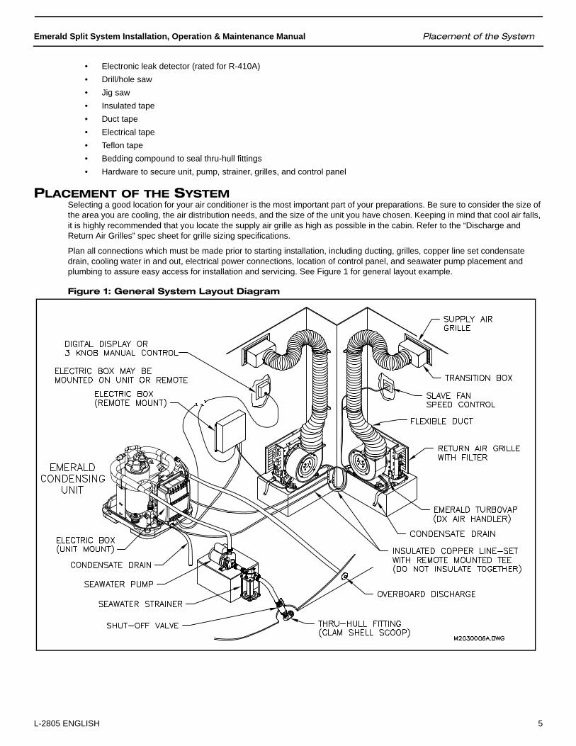
PLACEMENT OF THE SYSTEMSelecting a good location for your air conditioner is the most important part of your preparations. Be sure to consider the size of the area you are cooling, the air distribution needs, and the size of the unit you have chosen. Keeping in mind that cool air falls, it is highly recommended that you locate the supply air grille as high as possible in the cabin. Refer to the “Discharge and Return Air Grilles” spec sheet for grille sizing specifications.
Plan all connections which must be made prior to starting installation, including ducting, grilles, copper line set condensate drain, cooling water in and out, electrical power connections, location of control panel, and seawater pump placement and plumbing to assure easy access for installation and servicing. See Figure 1 for general layout example.
Figure 1: General System Layout Diagram

Clearances and Accessibility Emerald Split System Installation, Operation & Maintenance Manual
6 L-2805 ENGLISH
CLEARANCES AND ACCESSIBILITYDO NOT locate the unit:
• Where water may rise into the unit.• Where the noise would prove to be a nuisance to the owner (i.e., salons, decks, sleeping cabins, etc.).
AVOID:
• Direct tubing contact with water pipes, ductwork, floor joists, floors, and walls.• Suspending refrigerant tubing from structure with rigid wire or straps that would come in contact with tubing.
DO locate the unit:
• To minimize the length of refrigerant piping required.• To provide adequate service clearances.• On a level surface or other sturdy platform.• Isolated from the structure to avoid transmission of vibrations.
DO:
• Leave slack between structure and unit to absorb vibration.• When passing refrigerant tubes through the bulkhead, seal the opening with RTV or a pliable silicon-based caulk.• Ensure that the suction and liquid line tube diameters are appropriate for unit capacity.• Avoid unnecessary turns and bends by running refrigerant tubing as directly as possible.• In general, short runs of refrigerant piping are better than long runs. If practical, locate the unit accordingly.
SYSTEM SIZINGFor proper performance, the equipment and ductwork must be adequate for moving about 400 CFM of indoor air for every ton of cooling capacity to be installed. If they are not, change the ductwork or equipment accordingly.
MOUNTING THE CONDENSING UNIT & ELECTRICAL BOXThe location of the condensing unit should be dry and accessible for service, and provide the most direct routing of refrigerant line sets relative to the DX air handler location(s). The condensing unit should be installed lower than the DX air handlers so the refrigerant oil returns to the compressor.
The condensing unit should be secured to a horizontal surface that is designed for the weight of the unit and torsion loads from the vessel’s movement. The condensing unit should be mounted with one of the two drains pointing aft; the base pan can be rotated to accomplish this configuration. Bolt the base pan at four points using the holes in the four corners of the base pan. If the installation location is such that the corners do not contact a suitable surface, optional Dometic mounting clip assemblies (P/N: 293600453; not included) can be used instead by hooking them over the base pan at four locations and bolting them to a sturdy surface.
The electrical box may be remotely mounted to a bulkhead or sturdy frame. However, the electrical box may contain a position-sensitive relay on multi-ton condensers. The box can be remote-mounted in the same position as it sits on the condensing unit, or if another position is needed, open the box and rotate the relay bracket to the proper position.
MOUNTING THE DX AIR HANDLERThe DX air handler should be installed as low as possible (such as under a V-berth, dinette seat or bottom of a locker) and the supply air should be ducted as high as possible. This type of installation creates an ideal air flow condition and will prevent short cycling.
Securely fasten the DX air handler to a solid, level surface using the two mounting clips and the vibration isolators on the drain pan. be sure that it has at least 2 inches (51 mm) of air space in front of it to provide proper ventilation. Rotate the blower, if necessary, to provide the most direct route of ducting to the supply air grille(s) or transition boxes.
To rotate the blower, loosen the adjustment screw on blower mount ring, rotate blower to desired position, and then tighten the adjustment screw.
CONDENSATE DRAIN LINESDrain lines must be installed at the DX air handler and at the condensing unit. During conditions of high humidity, condensate may be produced at a rate of up to 2 gallons (7.6 liters) per hour.

Emerald Split System Installation, Operation & Maintenance Manual Copper Line Sets
L-2805 ENGLISH 7
With this in mind, it is important to route condensate drains downward to a sump pump. Do not route DX air handler condensate drain lines directly to the bilge (see warning below). Condensing unit drain lines may terminate in the bilge because the condensing unit does not handle air.
1. The DX air handler condensate drain pan has two 1/2” FPT drain fittings. You can use both drains (preferred) or just the drain in the aft-most-facing position.
Screw the supplied PVC hose barbs into the threaded drain fittings using teflon tape for a watertight seal and tighten them securely but do not overtighten. The two drains may be teed together, provided there is a minimum drop of 2 inches (51 mm) from the drain pan to the tee fitting. Use 5/8” hose and stainless steel hose clamps on all drain lines.
Install plug in drain fitting not used.
Route the DX air handler’s condensate drain hose to a sealed condensate or shower sump pump (see warning below). Drain hose must be routed downward to allow water to flow via gravity downhill.
2. The condensing unit has two 1/2” FPT drain fittings in its condensate drain pan. You can use both drains (preferred) or just the drain in the aft-most-facing position.
Screw the supplied PVC hose barbs into the threaded drain fittings using teflon tape for a watertight seal and tighten them securely but do not overtighten. The two drains may be teed together, provided there is a minimum drop of 2 inches (51 mm) from the drain pan to the tee fitting. Use 5/8” hose and stainless steel hose clamps on all drain lines.
Route the condensing unit’s condensate drain hose to a sealed condensate or shower sump pump or to the bilge. Drain hose must be routed downward to allow water to flow via gravity downhill.
Install plug in drain fitting not used.
3. Test: After the condensate drain installations are complete, test each installation by pouring a quart (1 liter) of water into the pan and checking for good flow. Occasionally pour a bleach and water solution into the pan to clean any algae or sediment out of the lines.
COPPER LINE SETSRefrigeration-grade tubing is required to connect the refrigerant circuit from the evaporator to the condensing unit. You must use tubing with the proper diameter and wall thickness specified for R-410A pressures. See Table 1.
Refrigerant tubing is normally soft drawn and nitrogen purged. All refrigerant lines should be capped to protect against moisture and dust infiltration until the flare connections are made to the evaporator and condenser base valves.
Extreme care must be taken not to crush or kink any portion of either line set. Use proper tools for line bending, avoiding sharp bends or kinks. Any kinked or crushed section must be replaced. There should be no vertical loops (oil traps) in the copper lines. Any excess tubing should be coiled in a horizontal plane and secured to prevent vibration.
Keep tubing clear of bilge water, steering cables and similar obstructions. Secure tubing approximately every 12 inches (30 cm) to prevent vibration and/or chafing. DO NOT CRUSH INSULATION.
When using multiple evaporators, ensure that the dual, triple or quad fittings are sized correctly to allow correctly sized tubing to be connected to DX air handler fittings and provide proper refrigerant flow to and from each DX air handler.
REFRIGERANT LINE SIZINGSee Table 2 for required tubing sizes. Using smaller refrigerant lines may decrease performance up to 10%. These sizes are suitable for line lengths of 50 feet (15.24 m) or less. It also assumes that the evaporator will not be more than 20 feet (6.1 m)
WARNINGDo not terminate DX air handler condensate drain lines within 3 feet (1 meter) of any outlet of engine exhaust systems, nor in a compartment housing an engine or generator, nor in a bilge, unless the drain is properly connected to a sealed condensate or shower sump pump. Exhaust and/or bilge fumes can travel up a drain line and mix with the return air blowing into living areas which could cause illness or death.
Table 1: Tubing Diameter and Required Wall Thickness for R-410A
Tube OD(inches)
Up to 1/2 5/8 3/4 7/8
Wall Thickness(inches)
0.028 0.035 0.042 0.045
Copper Line Sets Emerald Split System Installation, Operation & Maintenance Manual
8 L-2805 ENGLISH
above or below the condensing unit. Longer runs and greater lifts are not recommended. If a run of more than 50 feet (15.24 m) is required, contact your Distributor or the Dometic Marine Service Department at +1 954-973-2477 for assistance.
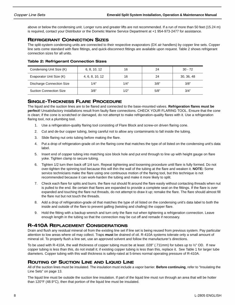
REFRIGERANT CONNECTION SIZESThe split-system condensing units are connected to their respective evaporators (DX air handlers) by copper line sets. Copper line sets come standard with flare fittings, and quick-disconnect fittings are available upon request. Table 2 shows refrigerant connection sizes for all units.
SINGLE-THICKNESS FLARE PROCEDUREThe liquid and the suction lines are to be flared and connected to the base-mounted valves. Refrigeration flares must be perfect! Unsatisfactory installations result from faulty flare connections. CHECK YOUR FLARING TOOL. Ensure that the cone is clean; if the cone is scratched or damaged, do not attempt to make refrigeration-quality flares with it. Use a refrigeration flaring tool, not a plumbing tool.
1. Use a refrigeration-quality flaring tool consisting of Flare Block and screw-on driven flaring cone.
2. Cut and de-bur copper tubing, being careful not to allow any contaminants to fall inside the tubing.
3. Slide flaring nut onto tubing before making the flare.
4. Put a drop of refrigeration-grade oil on the flaring cone that matches the type of oil listed on the condensing unit’s data label.
5. Insert end of copper tubing into matching size block hole and put end through to line up with height gauge on flare yoke. Tighten clamp to secure tubing.
6. Tighten 1/2 turn then back off 1/4 turn. Repeat tightening and loosening procedure until flare is fully formed. Do not over-tighten the spinning tool because this will thin the wall of the tubing at the flare and weaken it. NOTE: Some service technicians make the flare using one continuous motion of the flaring tool, but this technique is not recommended because it can work-harden the tubing and make it more likely to split.
7. Check each flare for splits and burrs. the flare nut should fit around the flare easily without contacting threads when nut is pulled to the end. Be certain that flares are expanded to provide a complete seat on the fittings. If the flare is over expanded and touching the flare nut threads, do not attempt to draw it up; remake the flare. The flare should almost fill the flare nut but not touch the threads.
8. Add a drop of refrigeration-grade oil that matches the type of oil listed on the condensing unit’s data label to both the inside and outside of the flare to prevent galling (twisting and chafing) the copper flare.
9. Hold the fitting with a backup wrench and turn only the flare nut when tightening a refrigeration connection. Leave enough length in the tubing so that the connection may be cut off and remade if necessary.
R-410A REPLACEMENT CONSIDERATIONSDrain and flush any residual mineral oil from the existing line set if line set is being reused from previous system. Pay particular attention to low areas where oil may collect. Traps must be drained of oil. R-410A systems tolerate only a small amount of mineral oil. To properly flush a line set, use an approved solvent and follow the manufacturer’s directions.
To be used with R-410A, the wall thickness of copper tubing must be at least .028" (.711mm) for tubes up to ½" OD. If new copper tubing is less than this, do not install it; if existing copper tubing is less than this, replace it. See Table 1 for larger tube diameters. Copper tubing with this wall thickness is safety-rated at 5-times normal operating pressure of R-410A.
ROUTING OF SUCTION LINE AND LIQUID LINE All of the suction lines must be insulated. The insulation must include a vapor barrier. Before continuing, refer to “Insulating the Line Sets” on page 13.
The liquid line must be outside the suction line insulation. If part of the liquid line must run through an area that will be hotter than 120°F (48.9°C), then that portion of the liquid line must be insulated.
Table 2: Refrigerant Connection Sizes
Condensing Unit Size (K) 6, 8, 10, 12 16 24 30 - 72
Evaporator Unit Size (K) 4, 6, 8, 10, 12 16 24 30, 36, 48
Discharge Connection Size 1/4” 1/4” 3/8” 3/8”
Suction Connection Size 3/8” 1/2” 5/8” 3/4”

Emerald Split System Installation, Operation & Maintenance Manual Copper Line Sets
L-2805 ENGLISH 9
• Seal the holes where the refrigerant piping enters the engine room.• Be careful not to kink or dent the refrigerant lines. Kinked or dented lines will cause poor performance or compressor
damage.
Filter DryerThe liquid line filter dryer is factory-installed. Any time the refrigeration system has been opened for service, you must replace the filter dryer with an equivalent filter dryer rated for R-410A.
BACKSEATING SERVICE VALVESThe Emerald condensing unit is equipped with service valves to ensure safe handling of the high-pressure R-410A refrigerant. The unit is shipped with the valve frontseated (downward position) to contain the factory charge in the unit. Refer to Figure 2.
• The stem cap should be torqued to 10 foot-pounds for seating the stem.• The stem is sealed primarily by backseating and torquing the valve. See “Final Charge Adjustment” on page 21 for
torque values.• The stems have a 5/16” square head on the suction valve and 1/4” on the liquid valve.• The stem has a packing seal instead of an O-ring. The packing gland should be tightened after each use to prevent
leakage. The torque value for the packing gland is 7 foot-pounds. Do not overtighten. Packing gland leaks and resulting damage are not covered under warranty.
• Gauge hoses can be connected and disconnected without the presence of system pressure. The gauge port is isolated from the system if the stem is backseated.
• The gauge ports have a standard core valve, which can be removed and replaced while the stem is backseated.
Figure 2: Service Valves Shown in Frontseated Position
PRESSURE TEST AND LEAK CHECKINGOnce the refrigerant line-set connections are made a pressure test and a leak check of the system must be performed.
NOTE: The base valves on the unit are shipped in the frontseated position to retain the refrigerant in the condensing unit. These valves must not be opened until the system is ready for operation.
CAUTIONDo not leave system open to atmosphere any longer than necessary for installation. The compressor POE oil is extremely susceptible to moisture absorption and could cause compressor failure. Ensure ends of tubing are sealed before and during installation.
Discharge Valve Suction Valve
Copper Line Sets Emerald Split System Installation, Operation & Maintenance Manual
10 L-2805 ENGLISH
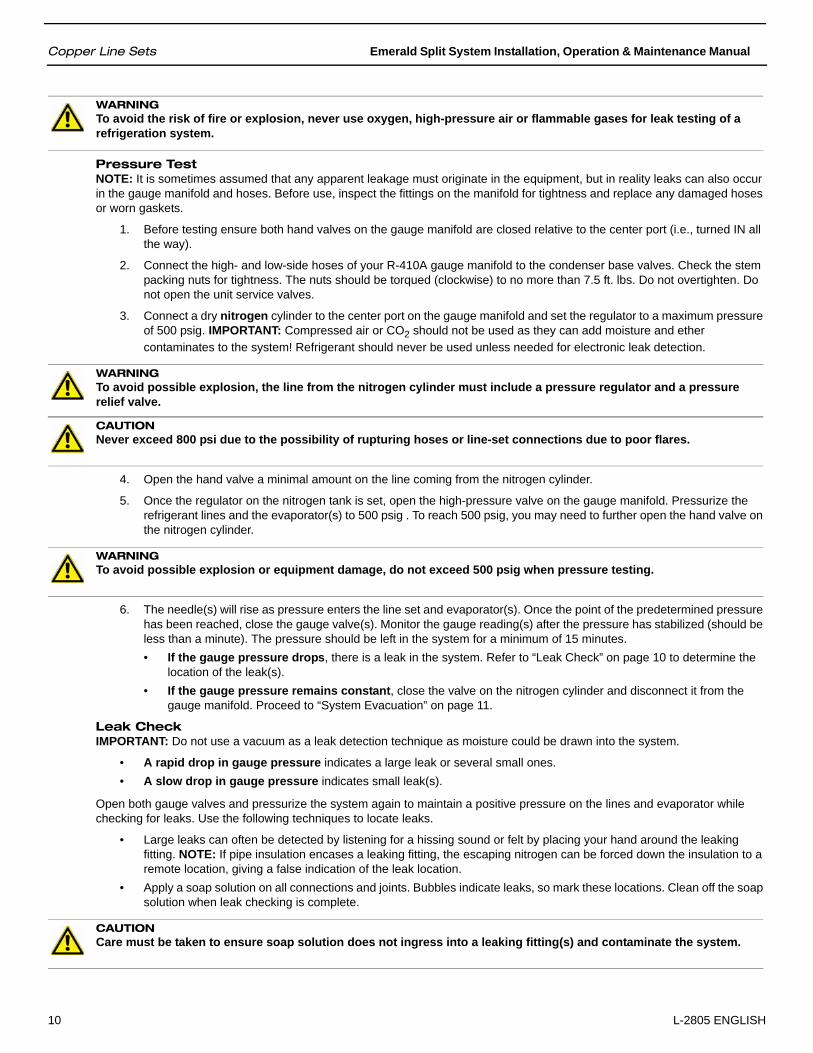
Pressure TestNOTE: It is sometimes assumed that any apparent leakage must originate in the equipment, but in reality leaks can also occur in the gauge manifold and hoses. Before use, inspect the fittings on the manifold for tightness and replace any damaged hoses or worn gaskets.
1. Before testing ensure both hand valves on the gauge manifold are closed relative to the center port (i.e., turned IN all the way).
2. Connect the high- and low-side hoses of your R-410A gauge manifold to the condenser base valves. Check the stem packing nuts for tightness. The nuts should be torqued (clockwise) to no more than 7.5 ft. lbs. Do not overtighten. Do not open the unit service valves.
3. Connect a dry nitrogen cylinder to the center port on the gauge manifold and set the regulator to a maximum pressure of 500 psig. IMPORTANT: Compressed air or CO2 should not be used as they can add moisture and ether contaminates to the system! Refrigerant should never be used unless needed for electronic leak detection.
4. Open the hand valve a minimal amount on the line coming from the nitrogen cylinder.
5. Once the regulator on the nitrogen tank is set, open the high-pressure valve on the gauge manifold. Pressurize the refrigerant lines and the evaporator(s) to 500 psig . To reach 500 psig, you may need to further open the hand valve on the nitrogen cylinder.
6. The needle(s) will rise as pressure enters the line set and evaporator(s). Once the point of the predetermined pressure has been reached, close the gauge valve(s). Monitor the gauge reading(s) after the pressure has stabilized (should be less than a minute). The pressure should be left in the system for a minimum of 15 minutes.• If the gauge pressure drops, there is a leak in the system. Refer to “Leak Check” on page 10 to determine the
location of the leak(s).• If the gauge pressure remains constant, close the valve on the nitrogen cylinder and disconnect it from the
gauge manifold. Proceed to “System Evacuation” on page 11.
Leak CheckIMPORTANT: Do not use a vacuum as a leak detection technique as moisture could be drawn into the system.
• A rapid drop in gauge pressure indicates a large leak or several small ones. • A slow drop in gauge pressure indicates small leak(s).
Open both gauge valves and pressurize the system again to maintain a positive pressure on the lines and evaporator while checking for leaks. Use the following techniques to locate leaks.
• Large leaks can often be detected by listening for a hissing sound or felt by placing your hand around the leaking fitting. NOTE: If pipe insulation encases a leaking fitting, the escaping nitrogen can be forced down the insulation to a remote location, giving a false indication of the leak location.
• Apply a soap solution on all connections and joints. Bubbles indicate leaks, so mark these locations. Clean off the soap solution when leak checking is complete.
WARNINGTo avoid the risk of fire or explosion, never use oxygen, high-pressure air or flammable gases for leak testing of a refrigeration system.
WARNINGTo avoid possible explosion, the line from the nitrogen cylinder must include a pressure regulator and a pressure relief valve.
CAUTIONNever exceed 800 psi due to the possibility of rupturing hoses or line-set connections due to poor flares.
WARNINGTo avoid possible explosion or equipment damage, do not exceed 500 psig when pressure testing.
CAUTIONCare must be taken to ensure soap solution does not ingress into a leaking fitting(s) and contaminate the system.

Emerald Split System Installation, Operation & Maintenance Manual Copper Line Sets
L-2805 ENGLISH 11
• If the leaks cannot be located with the previous methods, an electronic leak detector should be used. For this procedure, add a trace of R-410A refrigerant to the nitrogen in the system (if permitted by current EPA regulations). NOTE: Ensure the electronic leak detector you use is capable of sensing HFC-type refrigerants.
Repeat the procedures above until all leaks are found and repaired. After repair, repeat the steps in “Pressure Test” on page 10.
SYSTEM EVACUATIONIf you have confirmed that the system maintains pressure, the line set and evaporator(s) are now ready for evacuation of the nitrogen (or nitrogen/refrigerant mixture if an electronic leak detector was needed) from the system.
NOTE: Service valves are backseating-type valves.
Your system is shipped with the valve stem(s) frontseated (closed) and caps installed. Do not open these valves until the system is completely evacuated.
There are two ways that your system can be evacuated: The Deep Vacuum Method or the Triple Evacuation Method. The Deep Vacuum Method is the preferred method. Use the Triple Evacuation Method (see Figure 3 and “Triple Evacuation Method Procedure” on page 12) when the vacuum pump being used will only pump down 28 inches of mercury vacuum and your system does not contain liquid water. Otherwise, use the Deep Vacuum Method (see Figure 3 and “Deep Vacuum Method Procedure” on page 11).
Deep Vacuum Method ProcedureRefer to Figure 3.
1. Connect the vacuum pump, R-410A manifold set with vacuum hoses, and charging cylinder as shown. Ensure the vacuum pump used is capable of pulling a vacuum of 200 microns. Begin with all valves fully closed.
2. Confirm proper pump and gauge operation. Open the shutoff valve that leads to the high vacuum gauge manifold. Start the pump. When the compound gauge (low side) reading drops approximately 29 inches of vacuum, open the valve to the thermocouple vacuum gauge and evacuate until the gauge reads 200 microns or less.
3. Close the valve to the thermocouple vacuum gauge. This avoids potential gauge damage from “pegging the meter”.
4. Open the high and low side valves on the gauge manifold. Keeping the valve on the charging cylinder closed, open the valve on the gauge manifold that leads to the cylinder.
5. Evacuate the system to about 29 inches Hg as measured by the compound (low side) gauge.
6. Open the valve to the thermocouple vacuum gauge. Evacuate until the gauge reads 200 microns or less.
7. Close the valve to the vacuum pump. Wait five minutes, then check the pressure on the thermocouple vacuum gauge. (See Figure 3.)• If the pressure is not more than 1000 microns, the system is leak-free and properly evacuated. Proceed to Step 8.• If the pressure rises, but holds at about 2000 microns, moisture and noncondensibles are still present. Open the
valve to the vacuum pump, and continue evacuation until moisture is removed.• If the pressure rises above 5000 microns, a leak is present. Go back to “Pressure Test and Leak Checking” on
page 9.
8. Close the valve to the thermocouple vacuum gauge. Close the valve to the vacuum pump. Shut off the pump.
WARNINGWhen using high-pressure nitrogen in the system, wear safety glasses and gloves. Secure the hose end to prevent injury to personnel or damage to property. Do not point the hose toward personnel or property. To prevent inhalation, the nitrogen should NOT be expelled into a confined space where personnel are working; the work area should be well ventilated.If the nitrogen is mixed with refrigerant , contact with an open flame or hot surface could create PHOSGENE GAS, which can cause respiratory problems or death.WARNINGIf skin or eyes come into contact with refrigerant, flush thoroughly with water. Skin contact with refrigerant can cause frostbite. Wear gloves at all times.

Copper Line Sets Emerald Split System Installation, Operation & Maintenance Manual
12 L-2805 ENGLISH
Figure 3: Deep Vacuum Graph
Triple Evacuation Method ProcedureRefer to Figure 4.
1. Pump system down to 28 inches of mercury and allow pump to continue operating for an additional 15 minutes.
2. Close manifold gauge valves and shut off vacuum pump.
3. Connect a nitrogen cylinder and regulator to the system and open until system pressure is 2 psig.
4. Close manifold valves and allow system to stand for one hour. During this time, dry nitrogen will be able to diffuse throughout the system absorbing moisture.
5. Repeat this procedure as indicated in Figure 4. The system will then be free of any contaminants and water vapor.
6. Pull into deep vacuum.
Figure 4: Triple Evacuation Method Diagram
500045004000350030002500200015001000
500
0 1 2 3 4 5 6 7
EVACUATE
BREAK VACUUM WITH DRY NITROGEN
WAIT
CHECK FOR TIGHT, DRY SYSTEM(IF IT HOLDS DEEP VACUUM)
CHARGE SYSTEM
EVACUATE
BREAK VACUUM WITH DRY NITROGEN
WAIT
EVACUATE

Emerald Split System Installation, Operation & Maintenance Manual Supply & Return Air Grilles
L-2805 ENGLISH 13
INSULATING THE LINE SETS
1. Do not insulate both lines together.
For best results insulate both the suction line and the liquid line, however only the suction line is mandatory.
2. Use 3/4” thick closed-cell-type tube insulation with an inside diameter equal to pipe size. Place dust caps on both ends of pipe. Slide the tube insulation on to each pipe prior to making connections.
3. After making the connections, push the tube insulation flush against the fitting. Trim if necessary to ensure a smooth application with no air pockets.
4. Do not seal insulation until after checking for and fixing all leaks.
5. Pipe insulation joints should be glued, not taped. There must be no air pockets between the pipe and the insulation. All insulation must be airtight to prevent condensation forming on pipes.
6. If the tube insulation is installed after the refrigerant circuit is connected, proceed as follows:• Use pre-slit insulation or cut existing tube insulation and wrap around pipe.• Apply insulation adhesive thoroughly along both cut edges.• Press the glued edges back together making sure a proper bond is made with no openings, gaps, or air pockets.
Do not use wire ties to hold insulation around pipe in lieu of adhesive.
7. Tie wraps, wire ties, or zip ties should NOT be used to secure insulation. Using these will compress the insulation and cause poor performance leading to condensation drips and damage to the vessel.
8. Use insulation tape to wrap the flare nut and base valve connections at both ends of each line set. There should be no exposed copper or brass on the line set.
DUCT & GRILLE INSTALLATIONTable 3 shows shows minimum duct diameters and their corresponding supply- and return-air grille minimum areas in square inches as needed for the various models of the Emerald System evaporators. See “MAINTENANCE” on page 29 for return-air filter cleaning instructions.
NOTE: To calculate the square-inch area of a round duct, multiply the radius (which is half of the diameter) by itself (r2) then multiply that number by 3.1416 (pi).
SUPPLY & RETURN AIR GRILLESInstall the supply-air grille as high as possible in a location that will provide uniform air distribution throughout the cabin. Grille louvers should be directed upward. In no instance should the supply-air discharge be directed towards a return-air grille, as this will cause the system to short cycle. Allow for adequate clearance behind the supply-air grille for the transition box and ducting connection.
Install the return-air grille as low and as close to the air conditioning unit as possible to ensure direct uninterrupted airflow to the evaporator. The return-air grille should have a minimum of 4 inches (10.2 cm) of clearance in front of it, free from any furniture or other obstructions.
DUCTINGGood airflow is critical for the performance of the entire system. It is highly dependent on the quality of the ducting installation. The ducting should be run as straight, smooth and taut as possible, minimizing the number of 90-degree bends (2 tight 90-
Table 3: Duct and Grille Sizes for Emerald System Evaporators
MODEL TVE-4 TVE-6 TVE-8 TVE-10 TVE-12 TVE-16
Duct Diameter (inches)
4 5 5 6 6 7
Duct Area (square inches)
19.6 19.6 19.6 28.3 28.3 38.5
Return-Air Grille (square inches)
88 88 98 140 140 168
Supply-Air Grille (square inches)
40 40 50 70 70 84
Ducting Emerald Split System Installation, Operation & Maintenance Manual
14 L-2805 ENGLISH
degree bends can reduce airflow by 25%). Table 3 shows minimum duct diameters and their corresponding supply- and return-air grille minimum areas in square inches.
If a transition box is used, the total area of supply air ducts going out of the box should equal the area of the supply duct feeding the box.
All ducting should:
• Be appropriately sized for each application.• Run as smoothly and as taut as possible.• Have as few bends or loops as possible.• Be securely fastened to prevent sagging during boat operation.• Have all excess ducting lengths trimmed off.• Not be flattened or kinked.• Insulated when located in high heat load areas (hull side, mechanical compartments, etc.)• Be properly protected against potential damage when routed through open areas.
Installation procedure:
1. Run the ducting from the DX air handler’s blower to the supply-air grille or transition box.
2. At one end, pull back the fiberglass insulation to expose the inner mylar duct hose.
3. Slide the mylar duct hose around the mount ring until it bottoms out.
4. Screw 3 or 4 stainless steel sheet metal screws through the duct hose into the mount ring. Make sure to catch the wire in the duct hose with the heads of the screws. Do not use band clamps, as the hose will slide off.
5. Wrap duct tape around the ducting and ring joint to prevent any air leaks.
6. Pull the insulation back up over the mylar to the ring and tape the joint.
7. Use the same connection method at the other end of the ducting run, making sure to remove any excess ducting.
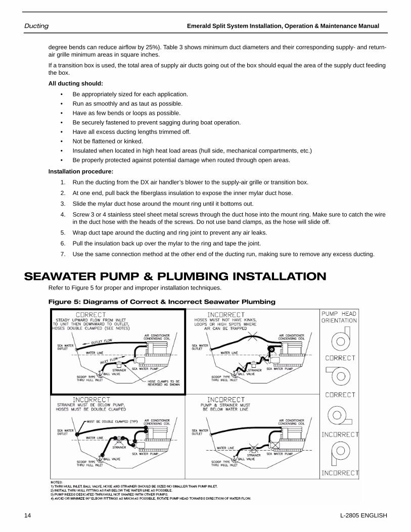
SEAWATER PUMP & PLUMBING INSTALLATIONRefer to Figure 5 for proper and improper installation techniques.
Figure 5: Diagrams of Correct & Incorrect Seawater Plumbing
Emerald Split System Installation, Operation & Maintenance Manual Seawater Pump
L-2805 ENGLISH 15
SEAWATER PUMPSince the seawater pump is centrifugal and not self-priming, it must be mounted so it is always at least one foot (305mm) below the water line regardless of which tack the vessel is on.
The pump may be mounted horizontally or vertically, however the discharge must always be above the inlet. The pump head should be rotated toward the direction of water flow. See Figure 5 for diagrams of correct and incorrect pump-head orientations.
NOTE: In rare situations and under certain variable conditions of direction and speed, a boat moving very fast could trigger the pump to shut down due to the extra water flow coming through the speed scoop. Normal pump function will resume when the boat slows or stops. Or, if the condition was sustained, the pump might lock out and require a reset by turning the pump’s power off then on again.
SEAWATER SPEED SCOOPInstall the seawater speed scoop intake as far below the water line and as close to the keel as possible in any application, but especially on a sailboat, to keep the intake submerged so air does not get into the system when the boat heels over. The speed scoop intake must face forward and not be shared with any other pump.
SEAWATER STRAINERA seawater strainer is mandatory between the shut off valve (seacock) and the pump to protect the pump from any foreign matter.
INSTALLATION PROCEDUREIMPORTANT:
• Avoid loops, high spots or the use of 90-degree elbows with seawater hose. Each 90-degree elbow is equivalent in pressure drop to 2.5 feet (76.2cm) of hose and a 90-degree elbow on the pump outlet is equivalent to 20 feet (609.6cm) of hose.
• Secure all hose connections with two stainless-steel hose clamps per fitting as close together as possible by putting the screws of the two clamps on opposite sides.
• Use teflon tape (2 to 3 wraps only) on all threaded connections. Tighten one and a half turns beyond hand tight. Do not over-tighten!
• Install the seawater system with an upward incline from the speed scoop and seacock, through the strainer, to the inlet of the pump and then up to the inlet of the air conditioning unit’s condenser coil.
• The discharge from the air conditioning unit should run to the seawater outlet thru-hull fitting, which should be located where it can be visually checked for water flow and as close as practicable to the waterline to reduce noise.
Follow these steps:
1. Install the speed scoop thru-hull inlet as close to the keel and as far below the water line as possible, facing forward. Bed the scoop with a marine sealant designed for underwater use.
2. Install a bronze, full-flow seacock on the speed scoop thru-hull inlet that meets ABYC specifications.
3. Install a seawater strainer below the level of the pump with access to filter.
4. Mount the pump above the strainer and at least one foot (305mm) below the waterline. (See Figure 5 for correct pump-head orientation positions.)
5. Connect the seacock and strainer with an uphill run of 5/8" (16mm) or larger for multi-ton units reinforced marine-grade hose.
6. Connect the discharge from the pump uphill to the bottom inlet of the air conditioning unit’s condenser coil with 5/8" (16mm) or larger reinforced marine-grade hose.
7. Connect the discharge from the condenser coil to the overboard discharge thru-hull fitting with 5/8" (16mm) or larger reinforced marine-grade hose.
8. Connect all metallic parts in contact with seawater to the vessel’s bonding system, including the speed scoop inlet, strainer, pump, and the air conditioner.
CAUTIONFailure to install a seawater strainer will void the pump warranty and possibly damage the system.

Overview Emerald Split System Installation, Operation & Maintenance Manual
16 L-2805 ENGLISH
ELECTRICAL CONNECTIONS, GROUNDING AND BONDING
OVERVIEWAll air conditioning units have a terminal strip mounted either inside or outside of the electric box. The terminal strip is labeled for proper connections of the electrical supply, ground wires and pump circuits. Wiring diagrams are provided in the electric box and in this manual The correct size circuit breaker should be used to protect the system as specified on the air conditioning unit’s data plate label. Wire gauge should be selected as per NEC to breaker. All connections shall be made with ring or fork terminals. Turn off the air conditioning power-supply circuit breaker before opening electric box.
Each air conditioning unit installed requires its own dedicated circuit breaker. If there is only one air conditioning unit installed, the seawater pump does not require a circuit breaker; the wiring from the seawater pump is connected to the terminal strip in the electric box. If two or more air conditioning units use the same seawater pump, the pump wires will be connected to a pump relay panel (PRP or PRX) which in turn has its own dedicated circuit breaker sized for the pump (20 amp max). Please see the wiring diagram furnished with the PRP or PRX (NOTE: PRP triac must have mounting screw installed in order to dissipate heat). Electrical connections in the bilge and/or below the waterline should use heat-shrink-type butt splices.
Field wiring must comply with ABYC electrical codes. Power to the unit must be within the operating voltage range indicated on the data plate. Properly sized fuses or HACR circuit breakers must be installed for branch circuit protection. See data plate for maximum fuse/circuit breaker size (mfs) and minimum circuit ampacity (mca). All units must be effectively grounded to minimize the hazard of electrical shock and personal injury. The following requirements are to be observed:
1. AC (Alternating Current) grounding (green wire) must be provided with the AC power conductors and connected to the ground terminal (marked “GRND” at the AC power input terminal block of the unit(s), per ABYC standard E-8, or equivalent.
2. Connections between the vessel’s AC system grounding conductor (green wire) and the vessel’s DC (Direct Current) negative or bonding system should be made as part of the vessel’s wiring, per ABYC standard E-9, or equivalent.
3. When servicing or replacing existing equipment that contains a chassis-mounted ground stud, the service person or installer must check the vessel’s wiring for the existence of the connection required in item 2 above.
ABYC standards are available from:
American Boat and Yacht Council613 Third Street, Suite 10Annapolis, MD 21403 USA
Telephone: (+1) 410-990-4460Fax: (+1) 410-990-4466Web: www.abycinc.org
The air conditioning unit must be connected to the ship’s bonding system to prevent corrosion due to stray electrical current. All pumps, metallic valves and fittings in the seawater circuit that are isolated from the air conditioning unit by PVC or rubber hoses must be individually bonded to the vessel’s bonding system also. This will help eliminate any possibility of corrosion due to stray current.
WARNINGOver-tightening can create eventual cracks within hours or days. Be sure to check for leaks before commissioning the boat to avoid sinking the boat.WARNINGConnect all metallic parts in contact with seawater to the vessel’s bonding system, including the speed scoop inlet, strainer, pump and the air conditioner. Failure to do so will void the warranty.
WARNINGFailure to connect all metallic parts in contact with seawater to the vessel’s bonding system will void the warranty.

Emerald Split System Installation, Operation & Maintenance Manual Safety
L-2805 ENGLISH 17
SAFETY
WIRINGWire size is important to ensure proper unit operation. The size must be sufficient to carry the minimum circuit ampacity listed on the unit’s data plate label. Dometic recommends sizing the wires to limit the voltage drop to a maximum of 2% from the main breaker or fuse panel to the condenser unit. Consult the NEC, CEC and all local codes to determine the correct wire gauge and necessary length of run for proper wiring.
1. To connect unit to power supply, route the power supply and ground wires through the high voltage entrance in the unit.
2. Connect the ground wire to the ground lug and power supply wires to the contactor.
3. Connect the low voltage wires to the terminal strip (if present) or to the wire leads. Route the low-voltage wire through the wire tie provided in the unit for restraint.
4. Connect thermostat to unit. If a proper room thermostat is not already present, install one at a suitable indoor location.
3-PHASE NOTICEIt is extremely important to ensure that wiring and phase sequencing of a 3-phase power source is correct. Marine wiring standards call for power source phases L1, L2, and L3 to be color-coded BLACK, WHITE, and RED, respectively. These must be connected to the unit with the proper sequence, otherwise, it will not operate properly. If the wiring sequence is incorrect, the unit’s compressor (scroll type only) and pump (if applicable) will run in the reverse direction at a significantly increased noise level.
WIRING DIAGRAMUse the wiring diagram provided with the digital or manual control you are installing.
MANUAL CONTROL PANEL
INSTALLATIONThe Manual Control Panel (MCP) should be located within cap tube length of the air conditioning unit. The 3-knob MCP is configured either vertically (as shown in Figure 6) or horizontally . The cut out size is 2.5 inches (64 mm) by 7.0 inches (178 mm); see MCP for orientation.
WARNINGTo avoid personal injury, shock, or death, open the electrical disconnect switch before electrically connecting the unit. Wiring must conform with NEC or CEC and all local codes.WARNINGTo avoid the risk of fire or equipment damage, use only 75°C minimum-rated copper conductors.
WARNINGConsult the National Electrical Code or a qualified electrician for proper wire size. Undersized wires could cause poor equipment performance, equipment damage, or fire.
WARNINGTo avoid electrical shock, injury, or death, wiring to the unit must be properly grounded.
Operation Emerald Split System Installation, Operation & Maintenance Manual
18 L-2805 ENGLISH
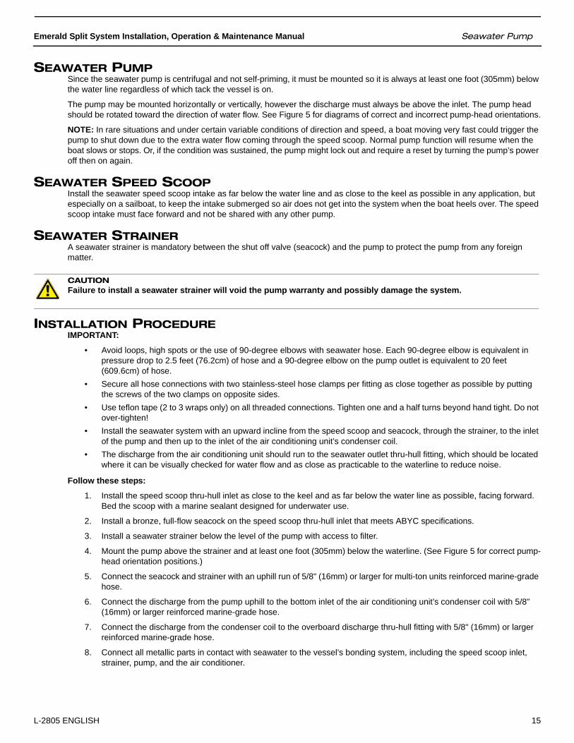
Figure 6: Manual Control Panel1. Once the cut out is made, carefully uncoil the copper cap tube with
return-air sensor (copper bulb) and route the control wires and cap tube through the hole and back to the air conditioning unit using caution not to kink the cap tube.
2. Mount the return-air sensor into the clips provided on the evaporator coil. If the return-air sensor cannot be mounted on the evaporator coil, mount it behind the return-air grille. The sensor must be mounted in the return-air stream.
3. Make electrical connections according to the wiring diagram found in the electric box and/or in the operations manual.
OPERATIONRefer to Figure 6.
1. Ensure seawater intake ball valve (seacock) is open.
2. Turn SYSTEM SWITCH (top control knob) to OFF.
3. Turn on AC circuit breaker. If the seawater pump has its own circuit breaker, turn that on also.
4. Turn the SYSTEM SWITCH (top control knob) to Fan (middle position); this energizes the fan and seawater pump.
5. If in cool mode, turn THERMOSTAT (bottom control knob) to the coolest position by rotating fully clockwise. If in heat mode, turn THERMOSTAT (bottom control knob) to the warmest position by rotating fully counter-clockwise.
6. Check for steady solid stream of seawater from the overboard discharge.
7. Turn FAN SPEED (middle control knob) clockwise to highest setting.
8. Verify that the fan is running and that there is steady airflow out of the supply-air grille.
9. Turn the SYSTEM SWITCH (top control knob) to ON; this will start the compressor.
10. To set the thermostat, allow sufficient time for the unit to cool/heat the area to the desired temperature. When the area is sufficiently cooled/heated, turn the THERMOSTAT (bottom control knob) slowly toward the center position until it clicks once. The thermostat is now set to maintain a constant temperature. While heating, if the ambient temperature is less than 50°F (10°C), set the FAN SPEED (middle control knob) to LOW for 5 to 10 minutes until the unit begins to heat well, then increase the fan speed for more heat output.
The thermostat on the MCP serves to cycle the compressor on and off and provides an automatic changeover from cooling to heating with a 3.5° differential. Rotating the thermostat to the left after it has been set for cooling will cause the unit to heat. If you rotate the thermostat to the right, the unit will cool. If the thermostat is left stationary after being set, the unit will cycle from cooling to neutral, or from heating to neutral depending on the requirement.
The condenser’s reversing valve switches the unit between heating and cooling modes, and it must be energized periodically to keep the internal parts moving freely. To accomplish this, for a few seconds once a month switch the air conditioning unit to HEAT if running in cool mode or to COOL if running in heat mode.
NOTE: Do not turn the unit off and immediately turn it back on. Allow at least 3 minutes for refrigerant pressure to equalize.
SLAVE FAN-SPEED CONTROLOn systems with multiple evaporators, only one DX air handler is dedicated as the master control and the others are slaved from that circuit. Usually the largest capacity DX air handler or the one dedicated to the most frequently occupied space is chosen as the main control unit.
When the master control unit energizes, all of the slave controls turn on. The only function of the slave speed control (model SCP) is to control the speed of the fan on that DX air handler.
Any DX air handler’s fan speed is controlled by a triac, whether it is controlled from the digital control’s circuit board, the mechanical 3-knob control (MCP), or slave fan speed control panel (SCP). Connecting triacs in series would negatively affect the performance of the fans; therefore, auxiliary/slave fans should be wired to the master unit’s pump control output. See the wiring diagrams included in this manual and in the condensing unit’s electrical box.

Emerald Split System Installation, Operation & Maintenance Manual Determining Refrigerant Charge
L-2805 ENGLISH 19
SYSTEM STARTUP
DETERMINING REFRIGERANT CHARGEFactory-Charge SettingsCondensing units are supplied with a charge sufficient for the condensing unit and the evaporator with 15 feet (4.57 m) of lineset. Table 4 shows the refrigerant charge of each unit as shipped from the factory.
Evaporators with quick disconnect fittings are charged with one ounce (0.0283 kg) of refrigerant (approximately 75 psig) as a holding charge.
Line sets with quick disconnect fittings are factory charged with the amount of refrigerant denoted on data plate.
Determining Charge by Table MethodOne foot (30.48 cm) of line set includes both the liquid and suction lines (see the example below the table). Refer to Table 4 to charge line sets constructed in the field. Use this formula to convert ounces to kilograms: 1 oz = 0.0283 kg. The condensing unit is factory-charged to include a system with a 15-foot (4.57 m) liquid line. Only add additional R-410A refrigerant if longer line sets are used.
EXAMPLE: If a line set is 20 feet long with a 1/4” liquid line and a 3/8” suction line, add charge for the 5 feet of line set over the base charge. To determine added charge, multiply 5 x 0.23, which equals 1.2 oz of refrigerant for the line set.
CAUTIONTo prevent compressor damage or personal injury:
• Do not overcharge system with refrigerant.• Do not operate unit in a vacuum or at negative pressure.• Do not disable the low pressure switch.• Use care when handling scroll compressors; dome temperatures could be hot.
CAUTIONTo prevent personal injury, wear safety glasses, protective clothing, and gloves when handling refrigerant.
CAUTIONTo prevent personal injury, fully backseat (turn counterclockwise) valve stem before removing gauge port caps and connecting and disconnecting manifold gauge hoses. Do not vent refrigerant to atmosphere. Recover during system repair or final unit disposal.
IMPORTANTDuring all installation and service work, follow all regulations of the Environmental Protection Agency (EPA). This system uses R-410A, an HFC (Hydrofluorocarbon). Violation of EPA regulations may result in fines or other penalties.
IMPORTANTNever operate the compressor with the suction valve closed to “test the compressor’s pumping efficiency”. In some cases, this can result in serious compressor damage and loss of warranty coverage.

Determining Refrigerant Charge Emerald Split System Installation, Operation & Maintenance Manual
20 L-2805 ENGLISH
Table 4: Factory Refrigerant Charge Per Condenser Model
Emerald R-410A Charging Table
Note:• Emerald systems are dual metered at the air coil for cool mode and at the condensing unit for heat mode.
• Emerald systems use Thermal Expansion Valves to optimize system operation and thus cannot be charged using superheat method.
• A properly operating TXV will maintain Superheat in range of 10 to 25 degrees.
• System must be charged by Table or Subcooling method.
Charging system by Table method:• Condensing unit is factory charged with refrigerant for system including 15 foot of lineset.
• If lineset is longer than 15 foot then add refrigerant shown for lineset length. If lineset is between lengths listed in table, either interpolate or round down.
Charging system by Subcooling method:• Charge in cool mode steady state to achieve 1 to 4 degrees at condensing unit base valve. Or, if pressure port is available at evaporator inlet, charge for 5 to 10 degrees F of subcooling just upstream of evaporator TXV.
• System overcharged with refrigerant can lead to catastrophic failure. Symptoms are high head pressure, high running current, and high subcooling.
• If you need assistance using the Subcooling method, contact Dometic for more information.
Unit Specifics Tube Diameter Lineset Factory
Unit Liquid Suction Charge/ft Charge (oz)6-10k 1/4 3/8 0.23 1412k 1/4 3/8 0.23 1716k 1/4 1/2 0.26 1724k 3/8 5/8 0.64 4230k 3/8 3/4 0.67 4636k 3/8 3/4 0.67 5048k 3/8 3/4 0.67 64
Charge Added for Longer Line SetsCharge in ounces to be added by installer for Lineset in feet of length noted
Unit 15 20 25 30 40 45 506-10k - 1.2 2.3 3.5 5.8 6.9 8.112k - 1.2 2.3 3.5 5.8 6.9 8.116k - 1.3 2.6 3.9 6.5 7.8 9.124k - 3.2 6.4 9.6 16.0 19.2 22.430k - 3.4 6.7 10.1 16.8 20.1 23.536k - 3.4 6.7 10.1 16.8 20.1 23.548k - 3.4 6.7 10.1 16.8 20.1 23.5
Emerald Split System Installation, Operation & Maintenance Manual Factory-Charge Release Into System
L-2805 ENGLISH 21
FACTORY-CHARGE RELEASE INTO SYSTEM1. Remove the service valve stem caps.
2. After successful evacuation, the base valves can be opened starting with the liquid line valve. Rotate the valve stem counter clockwise to the midseated position. The pressure will rise quickly on the high-side gauge followed by a steady rise on the low-side gauge as the refrigerant passes through the metering device.
3. Open the suction-side base valve to the midseated position. This will allow the system pressures to be monitored when the unit is running and allow for the addition of refrigerant if necessary.
NOTE: R-410A refrigerant cylinders contain a dip tube which allows liquid refrigerant to flow with the cylinder in an upright position. R-410A refrigerant should be charged in the upright position with the liquid gradually metered into the unit.
SYSTEM STARTUP1. If manifold gauge set hoses are connected, proceed to step 3. Otherwise, connect the gauge hoses. Ensure the
service valve stems are fully backseated and the manifold gauge set hoses are connected to the service valve ports.
2. Rotate the base valve stems one-half turn clockwise so pressure can be read by the manifold gauges.
3. Close electrical disconnects to energize system.
4. Set cabin thermostat to COOL and fan control to ON or AUTO. Set the temperature control well below room temperature. Operate unit for 20 minutes. Check system refrigerant charge.
FINAL CHARGE ADJUSTMENTRun the unit for approximately 20 minutes to stabilize the refrigerant pressures. The following guidelines and methods are used to check operation and to ensure that the refrigerant charge is within limits:
Adding/Removing Refrigerant ChargeIf additional charge is needed based on line set length:
1. Connect the center hose from the gauge manifold to the R-410A charging cylinder. The cylinder valve should be opened and the hose purged of air.
2. Add refrigerant through the low side of the gauge manifold in the form of liquid in small amounts at a time to prevent slugging the compressor. Once the system is charged with amount indicated by Table 4, close the valve on the charging cylinder but do not remove the hose.
3. Turn the liquid-line base valve fully counter clockwise (backseated). Open both gauge manifold valves to allow the residual liquid/vapor in the hoses to return into the suction side.
If less charge is needed based on line set length:
1. If less charge is needed, recover the excess R-410A. Use the factors in Table 4 to determine the installed liquid line charge needed.
Verifying System Refrigerant Charge
1. Measure the suction and liquid pressures at the service valves, the liquid line temperature at the condensing unit, and the condensing unit amps. For reference to the table, measure the inlet water temperature, and the indoor wet and dry bulb temperatures.
2. Look up the required subcooling from Table 4. This information applies to systems with a TXV.
3. Calculate subcooling. First determine saturated liquid temperature from PT chart using measured liquid pressure. Then subtract liquid temperature measured in step 1 from the saturated liquid temperture.
4. If charging system by subcooling method, adjust R-410A charge to obtain the required subcooling as described above. That is, add charge when the liquid subcooling is less than requirement, and recover charge when above the requirement.
CAUTIONUse only refrigerant which is certified to meet ARI Standard 700. Used refrigerant may cause compressor damage and will void the warranty. (Most portable machines cannot clean used refrigerant well enough to meet this ARI Standard.)

System Startup Emerald Split System Installation, Operation & Maintenance Manual
22 L-2805 ENGLISH
5. Compare suction pressure with performance data. The suction pressure depends on which coil model is installed, fan speed, and the indoor air flow and wet bulb. Do not adjust refrigerant based on suction pressure unless there is a gross undercharge.
6. Compare the liquid pressure to the specification data. Liquid pressure depends on the suction pressure, outdoor temperature, and the liquid subcooling. Charge adjustments should be based on the required subcooling determined above.
7. Check the condensing unit amps to the specification data. The amp reading will track with the liquid pressure.
8. If the system is performing properly, fully backseat liquid valve. Remove the manifold gauge hose from the valve port liquid side. Open both gauges to pull refrigerant to low side pressure. Remove suction side hose from port.
9. Fully backseat suction valve and torque valve stems to the values shown in Table 5.
10. Reinstall service port cores and caps. Torque caps to 10 foot pounds.
11. Perform a final refrigerant leak test on the valves and sweat connections.
12. Return the thermostat to the desired settings.
VERIFYING ACCEPTABLE OPERATING PRESSURESCalculating high-side and low-side pressures is difficult due to the variables involved. The high-side (liquid line) pressure on a properly operating water-cooled unit is determined by the temperature of the seawater, water flow, and how clean the condenser coil is. The low-side (suction line) pressure is affected by fan speed, static pressure, and wet and dry bulb readings. For this reason, the refrigerant charge should be properly measured into the system for optimum operation (see Table 4).
The following tables should be used as a reference to monitor performance in cool mode at high fan speed and should not be used to charge the system.
Table 5: Tubing Size and Torque Value for Flare Connections Chart
Tubing Size Front/Back Seat Stem(Foot-Pounds)
Flare Nuts*(Foot-Pounds)
1/4” 10 9
3/8” 10 17
1/2” 16 30
5/8” 16 40
3/4” 22 52
*Packing Glands: 7 foot-pounds, all valve sizes.

Emerald Split System Installation, Operation & Maintenance Manual System Startup
L-2805 ENGLISH 23
Table 6: Head Pressures by Model Number
Table 7: Suction Pressures by Model Number
Emerald R-410A Condenser Cool Mode Operating Head Pressures (PSIG)
TEMPERATURE:For HEAD Pressure - Use Inlet Water Temperature.
60 85
Min Max Min Max Min Max Min Max Min Max Min Max Min Max Min MaxMODEL6k 186 216 206 236 226 256 246 276 266 296 286 316 306 336 326 356
8k 196 226 217 247 238 268 260 290 281 311 302 332 323 353 344 374
10k 192 222 213 243 234 264 255 285 276 306 297 327 318 348 339 369
12k 197 227 218 248 239 269 260 290 281 311 303 333 324 354 345 375
16k 204 234 225 255 246 276 267 297 288 318 310 340 331 361 352 382
24k 224 254 246 276 268 298 290 320 312 342 334 364 356 386 379 409
30k 243 273 266 296 288 318 311 341 334 364 357 387 379 409 402 432
36k 226 256 248 278 269 299 290 320 312 342 333 363 354 384 376 406
48k 217 247 239 269 260 290 282 312 303 333 325 355 346 376 367 397
HEAD pressure is dependant on water flow rate.Table is based on nominal 3 GPM/ton.If water flow is low, head pressure may be greater than listed.
555555 60 70
757575
6565
990
808080 85
70
Emerald R-410A Condenser Cool ModeOperating Suction Pressures (PSIG)
TEMPERATURE:For SUCTION Pressure - Use Return Air Temperature.
Min Max Min Max Min Max Min Max Min Max Min Max Min Max Min MaxMODEL6k 49 61 64 76 79 91 94 106 109 121 124 136 139 151 155 167
8k 55 67 70 82 85 97 99 111 114 126 129 141 144 156 158 170
10k 53 65 66 78 80 92 93 105 106 118 120 132 133 145 147 159
12k 51 63 63 75 75 87 87 99 100 112 112 124 124 136 136 148
16k 52 64 65 77 78 90 91 103 104 116 117 129 129 141 142 154
24k 59 71 71 83 84 96 96 108 108 120 121 133 133 145 145 157
30k 56 68 70 82 84 96 99 111 113 125 127 139 141 153 155 167
36k 52 64 66 78 80 92 94 106 108 120 122 134 136 148 150 162
48k 54 66 68 80 82 94 96 108 110 122 124 136 138 150 152 164
SUCTION pressure is strongly associated to Relative Humidity and fan speed. Table is based on 50-70% RH and high fan speed. Higher RH levels may result in higher pressures than listed.
990
8080
8585
7070
7575
6565
5555
6060

Final Checks Emerald Split System Installation, Operation & Maintenance Manual
24 L-2805 ENGLISH
FINAL CHECKS• Ensure all wiring and tubing are secure in the unit before adding panels and covers.• Securely fasten all panels and covers.• Leave this manual (and digital control manual, if any) with owner. Explain system operation and periodic maintenance
requirements outlined in manual.
Fill out “INSTALLATION CHECKLIST” on page 25.

Emerald Split System Installation, Operation & Maintenance Manual Final Checks
L-2805 ENGLISH 25
INSTALLATION CHECKLIST REVIEW PRIOR TO INSTALLATION AND AFTER
Table 8: Installation Checklist
Seawater Cooling System
Speed scoop located as far below the water line and as close to the keel as possible.
Shutoff valve and speed scoop properly sealed and tight.
Seawater pump is at least one foot below water line and securely mounted.
Strainer mounted below pump with access to filter.
Double/reversed stainless steel hose clamps on all hose connections.
Teflon tape on all threaded connections.
Hose runs uphill from speed scoop and seacock to strainer, pump, and air conditioning unit, then downhill (if possible) from air conditioning unit to overboard discharge.
Water flowing freely from overboard discharge while pump is running.
Pump relay panel, if used, must have its own circuit breaker sized for the pump (20 amp max).
All metal fittings must be bonded.
Mounting
DX air handler not in engine room or bilge areas, must be sealed away from exhaust or fumes
Proper spacing allowed around unit.
Securely attached to solid level platform with hold down clips provided.
Condensate drain routed aft and down hill to a sealed sump (not bilge).
Blower rotated toward supply-air grille.
Electrical
All butt connections on pump wire tightly crimped and heat shrunk.
AC power source installed and grounded/bonded in accordance with ABYC standards.
Control wires connected to terminal strip with fork or ring terminals.
Circuit breakers sized according to specifications on the data plate label.
Remote electrical box mounted with position-sensitive relay taken into consideration.
Digital control display cable is connected at both ends.
Pump Relay Panel (if used) has a dedicated circuit breaker sized for the pump but not to exceed 20 amps maximum.
Grilles and Ducting
Supply-air grille mounted as high as possible.
Return-air grille mounted as low and as close to the air conditioning unit as possible.
Return-air grille mounted away from bilge vapors or exhaust fumes.
Ducting is pulled taut, straight, smooth, and properly connected with no excess.
Line Sets
Pressure tested.
Evacuated.
No kinks or crushed piping and no vertical loops.
Correct insulation thickness and properly sealed.
Piping supported.

Cooling Mode Emerald Split System Installation, Operation & Maintenance Manual
26 L-2805 ENGLISH
QUICK-START OPERATIONS CHECKLIST
SERVICING
NOTE: In the following sections the liquid receiver, liquid line filter dryer, and suction accumulator will not be mentioned; this is to simplify the description of system operation. On all systems and in both modes of operation, the configuration of the discharge and suction lines between the reversing valve and compressor remain the same.
COOLING MODEIn cooling mode the reversing valve is NOT energized. Hot high-pressure gas is discharged from the compressor through the reversing valve to the water-cooled condenser coil. There, the hot gas gives up heat to the cooler water circulating through the coil. The heated water is then discharged overboard. As the gas is cooled it condenses into a liquid. It is then fed to the metering device on the evaporator, the thermal expansion valve (TXV). The TXV is the transition point of the low- and high-side of the system and regulates the flow of liquid refrigerant into the evaporator. As the liquid travels through the evaporator tubing it absorbs heat from the air passing through the finned coil. This causes the liquid refrigerant to boil off into a vapor. The low-pressure vapor is then returned to the reversing valve via the suction line and then to the compressor.
HEATING MODEIn heating mode, the reversing valve IS energized. The plunger in the valve body moves, changing the direction of the refrigerant flow. The suction line becomes the hot-gas discharge line. The hot-gas line to the condenser now becomes the liquid line. The hot gas flows to the air-cooled evaporator that is now the condenser. The cool air passing across the finned coil absorbs the heat from the refrigerant and is returned to the cabin as warm air. As the refrigerant gives up heat it again turns into a liquid. The liquid is returned to the condensing unit and metered through the TXV at the condensing unit into the water coil. The refrigerant passes through the water coil, which is now the low-side evaporator. Heat is absorbed from the water as it passes through the coil and the refrigerant boils off into a vapor. The vapor returns to the compressor via the reversing valve.
SCHEMATIC DIAGRAM OF REFRIGERANT SYSTEMFigure 7 on page 27 shows the the refrigerant systems for both Cool Mode and Heat Mode.
Table 9: Quick-Start Operations Checklist
Ensure seawater intake ball valve (seacock) is open.
Turn on the air conditioning circuit breaker. If the seawater pump has its own circuit breaker, turn that on.
Turn the system on.
Set the desired cabin temperature (set point).
Check for a steady solid stream of water from the overboard discharge.
Verify that there is steady airflow out of the supply-air grille.
If the unit does not appear to be operating properly, refer to Troubleshooting Guidelines.
NOTE: Do not turn the unit off and immediately turn it back on. Allow at least 3 minutes for refrigerant pressure to equalize.
WARNINGCare should be taken when attaching the low side of a gauge manifold in the Heat Cycle. On Emerald R-410A units, both base valves can see high pressure while in heating mode. High-pressure refrigerant can retard and damage a low-side gauge.

Emerald Split System Installation, Operation & Maintenance Manual Schematic Diagram of Refrigerant System
L-2805 ENGLISH 27
Figure 7: Schematic Diagrams of Refrigerant Systems in Cool Mode and Heat Mode

General Troubleshooting Emerald Split System Installation, Operation & Maintenance Manual
28 L-2805 ENGLISH
TROUBLESHOOTING
GENERAL TROUBLESHOOTINGIf you have a digital control, refer also to the troubleshooting section of the manual packaged with it.
Table 10: General Troubleshooting
PROBLEM POSSIBLE REASON/SOLUTION
System will not start. 1. DX air handler circuit breaker is off. Turn circuit breaker on at ship’s panel.2. Digital control is not turned on. Press the Power button.3. Wrong wiring at terminal strip. Check wiring diagram; correct if necessary.4. Input-line voltage is insufficient. Check power source (shore/generator) for proper
voltage. Check wiring and terminals for proper sizes and connections. Verify with a volt-meter that the power at the unit is the same as the power source.
5. Push-on connectors or butt splices became disconnected during installation. Disconnect power supply and open electric box, check wiring diagram, correct if necessary.
Fan is not running. Check the troubleshooting section of your digital control manual.
No cooling or heating. 1. Temperature set point is satisfied. Lower or raise set point.2. Obstructed seawater flow. Clean seawater strainer. Check for obstructions at speed
scoop thru-hull inlet. Check for a good steady flow from the overboard discharge.3. Seawater pump may be air-locked. Remove hose from pump discharge to purge air
from line.4. Loss of refrigerant gas. Check air conditioning unit for refrigerant oil leakage, call
service technician.5. Seawater temperature too high for cooling or too low for heating. Seawater
temperature will directly affect air conditioning unit’s efficiency. This air conditioning unit can effectively cool your boat in water temperature up to 90°F (32.2°C) and heat (if reverse-cycle option is installed) in water temperatures as low as 40°F (4.4°C).
6. Fan coil is iced (in cooling). Check your specific control troubleshooting section.7. Fan is not running. Check your specific control troubleshooting section.8. Seawater plumbing is air-locked. Ensure that seawater plumbing is installed per the
guidelines in this manual.9. Digital control is programmed for Cool or Heat only, or mechanical-control
thermostat is rotated too far toward either Cooler or Warmer setting. See the control’s Operations Manual for instructions.
10. High-pressure switch is open (in cooling) due to improper seawater flow. Strainer or intake may be plugged, seacock may be closed, check seawater hose for kinks or collapses. Verify pump operation. Check pump circuit breaker if applicable.
11. High-pressure switch is open (in heating) due to improper airflow. Remove any obstructions in return air stream. Clean return air filter and grille. Check for crushed or restricted ducting, ducting must be as straight, smooth and taut as possible.
12. High-pressure switch is open (in heating) due to high seawater temperature. System may cycle on high pressure if seawater temperature is above 55°F (12.8°C). Increase fan speed.
13. Compressor’s thermal overload is open due to either of the above reasons. Compressor needs to cool down. Turn system off for a while (it may take up to three hours to reset thermal overload).
No heating. Unit is in "cool only" mode, or reversing valve may be stuck. Tap reversing valve lightly with rubber mallet while unit is in heat mode. Call for service if that does not correct the problem.

Emerald Split System Installation, Operation & Maintenance Manual Return-Air Filter
L-2805 ENGLISH 29
MAINTENANCE
RETURN-AIR FILTERCheck the return air filter about once a month and clean or replace as necessary. To clean the filter, remove it from the unit, rinse with water
REVERSING VALVEReverse cycle units have a reversing valve. The valve must be energized periodically to keep the internal parts moving freely. To do this, switch the air conditioning unit into heat for a few seconds once a month.
SEAWATER STRAINEREnsure that your pump receives adequate seawater flow by regularly cleaning the strainer basket. Periodically check the overboard discharge for a steady stream of water. Check seawater intake speed scoop for obstructions. Be sure hoses are not looped, kinked, or crushed.
CONDENSER COIL CLEANINGA marine-growth-fouled coil reduces efficiency, raising total system pressure and decreasing its ability to produce cold air.
1. With the system turned off at the circuit breaker on the ship’s panel, disconnect the inlet and outlet connections of the condenser coil.
Low airflow. 1. Airflow is blocked. Remove any obstructions in return-air stream. Clean return-air filter and grille. Check for crushed or restricted ducting; ducting must be as straight, smooth and taut as possible.
2. Fan Coil is iced. See below.3. Fan speed is set to manual low. If the fan speed is set to manual low, press and
release the Fan button until the desired fan speed and airflow are reached. If you want automatic fan speed control, press and release the Fan button until the letter “A” displays.
Fan coil is iced. 1. Thermostat set point is too low. Raise set point. 2. Improper airflow. Remove any obstructions in return air stream. Clean return air filter
and grille. Check for crushed or restricted ducting, must be as straight, smooth and taut as possible. See the Digital Controls Troubleshooting section below for reprogramming options.
3. Supply air is short-cycling. Redirect supply air so that is not blowing into the return air stream. Seal any air leaks on duct.
4. Humidity level too high. Close hatches and doors.5. When all else fails. Switch air conditioning unit to heat until ice melts or use hair
dryer to melt.
Water coil is iced in the Heating Mode.
Seawater temperature is below 40°F (4.4°C). Shut down system to prevent damage to condenser. Allow coil to defrost.
System runs continuously. 1. Set point temperature is improperly set: too low for cooling or too high for heating. Raise or lower set point.
2. Porthole or hatches open. Close all port holes and hatches.3. Seawater temperature too high for cooling or too low for heating. Seawater
temperature will directly affect the air conditioning unit’s efficiency. This air conditioning unit can effectively cool your boat in water temperatures up to 90°F (32.2°C) and heat in water as low as 40°F (4.4°C).
4. Improper air sensor location. Check your specific control troubleshooting section.
Table 10: General Troubleshooting (continued)
PROBLEM POSSIBLE REASON/SOLUTION

Winterization Emerald Split System Installation, Operation & Maintenance Manual
30 L-2805 ENGLISH
2. Use chemical-resistant hoses (MAS white PVC 5/8" I.D., etc.) to connect the inlet of the condenser coil to the outlet of a chemical resistant, submersible pump (MAS P-500 pump, etc.) and let the hose connected to the coil outlet flow freely into the container mentioned below.
3. Place a strainer or piece of screen over the inlet of the pump and submerse the pump into a container filled with a 5% solution of muriatic or hydrochloric acid and fresh water or use a premixed over-the-counter solution. Use as large a container as possible to hold the solution (5-25 gallons [19-95 liters]).
4. Power the pump and circulate the solution through the condenser coil for 15-45 minutes depending upon the size of the coils and the extent of the contamination. Visual inspection of the solution in the container should indicate when the contamination removal has stopped.
5. Circulate fresh water through the coil to flush any residual acid from the system.
6. Restart the system and check operational parameters to ensure thorough cleaning has taken place. Additional cleaning may be necessary with extreme contamination.
WINTERIZATIONThere are several methods of winterization, some of which work better than others. Any method that causes the antifreeze solution to flow downward is the method of choice. By this means, the antifreeze solution displaces any trapped water and eliminates the possibility of it freezing in hidden areas.
Choose the method that works best for you. In the following four methods, the first two use a 50/50 nonpolluting biodegradable antifreeze/water solution:
• Pump antifreeze solution into the overboard thru-hull fitting, and discharge through the intake thru-hull fitting.• Use the seawater pump to pump antifreeze solution through the system and discharge through the overboard thru-hull
fitting: Close sea cock, remove hose from strainer discharge, raise hose above pump (so pump does not lose its prime) and pour in antifreeze solution. Pump solution through system. The strainer and hose to sea cock need to be drained of water.
• Use pressurized air injected at the overboard discharge fitting to force system water through the seawater intake fitting, thus expelling any trapped water from the system.
• Use pressurized air injected at the seawater intake fitting to force system water through the seawater overboard discharge fitting, thus expelling any trapped water from the system.
In addition, since the seawater pump utilizes a magnetically driven impeller, remove the impeller from the wet-end assembly, wipe with an alcohol solution, and store in a warm, dry area until commissioning takes place.
OWNERS LIMITED WARRANTYAs hereinafter described, Dometic limits the duration of any implied warranty to the duration of the underlying express warranty and also disclaims any liability for consequential or incidental damages arising from any application, installation, use or malfunction of any warranted product.
SECTION I - WHAT’S COVEREDWhat does the Limited Warranty cover?
Products manufactured by Dometic Corporation (Dometic) are under limited warranty to be free from defects in workmanship or materials. This being under normal use and service, with the obligation of Dometic under this limited warranty, being limited to replacing or repairing any component(s) which shall disclose defects within the limits defined in Section III. Which upon examination by Dometic, shall appear to the satisfaction of Dometic to be defective or not up to specifications.
WARNINGAvoid spilling or splashing the solution. Follow all warnings and recommendations given by the manufacturer of any acids or premixed solutions.
CAUTIONFor the purpose of protecting the environment, dispose of any contaminated acid solutions in accordance with federal, state and/or local regulations.
CAUTIONCollect all discharged liquids and recycle or dispose of in a proper manner in accordance with federal, state and/or local regulations.
Emerald Split System Installation, Operation & Maintenance Manual Section II - What’s Not Covered
L-2805 ENGLISH 31
This Limited Warranty is made in lieu of all other express warranties, obligations, or liabilities on the part of Dometic. In addition, Dometic shall not be responsible for any incidental or consequential damages. In those instances in which a cash refund is made, such refund shall effect the cancellation of the contract of sale without reservation of rights on the part of the purchaser. Such refund shall constitute full and final satisfaction of all claims which the purchaser has or may have against Dometic due to any actual or alleged breach of warranty, either express or implied, including, without limitation, any implied warranty or merchantability or fitness for a particular purpose. Some states do not allow the exclusion or limitation of incidental or consequential damages so the above limitation may not apply to you.
The Dealer is not an agent for Dometic, except for the purpose of administering the above warranty to the extent herein provided. Dometic does not authorize the dealer or any other person to assume for Dometic any liability in connection with such warranty, or any liability or expense incurred in the replacement or repair of its products other than those expressly authorized herein. Dometic shall not be responsible for any liability or expense except as is specifically authorized and provided in this section.
Dometic reserves the right to improve its products, through changes in design or material without being obligated to incorporate such changes in products of prior manufacture. Dometic can make changes at any time in design, materials, or part of units of any one, model year, without obligation or liability to owners of units of the same year's model of prior manufacture.
This warranty gives you; the purchaser, specific legal rights, and you may also have other rights which vary from state to state. You also have implied warranty rights, including an implied warranty of merchantability, which means that your product must be fit for the ordinary purposes for which such goods are used. The duration of any implied warranty rights is limited to the duration of the express warranty as found in Section III. Some states do not allow limitations on how long an implied warranty lasts, so the above limitation may not apply to you.
SECTION II - WHAT’S NOT COVEREDWhat does this Limited Warranty not cover?
This Warranty Shall Not Apply to:
1. Failures resulting from improper installation or use contrary to instructions.
2. Failures resulting from abuse, misuse, accident, fire, or submergence.
3. Any part manufactured by Dometic, which shall have been altered so as to impair its original characteristics.
4. Any parts which fail as a result of misuse, improper application or improper installation.
5. Items not manufactured by Dometic, i.e., items, which are purchased from another manufacturer and supplied as received by Dometic without alteration or modification except as any part of a Dometic manufactured unit or component.
6. Components or parts used by or applied by the purchaser, as an integral part of products not manufactured by Dometic.
7. Labor resulting from difficult access to a Dometic product. The original installer or OEM is responsible for accessibility of unit.
8. Leaks due to improper installation of split systems and refrigeration systems, for example; packing glands, flare nuts, quick disconnects. The adjustment of the refrigerant charge on a split system should be charged to the original installer or OEM.
9. Freight Damage (see page 10 for instructions for handling freight damage).
10. Pumps that have been run dry, are water damaged or have blown freeze plugs.
11. Pumps with cracked heads.
12. Pump seals are not covered.
13. UV light bulbs are not covered.
14. Liquid line filter dryers are not covered.
15. Blowers with water damage.
16. Logic boards with water damage.
17. Logic boards with blown MOV's (Power Surge)
18. Mis-programmed displays.
19. Display heads with water damage.
20. Dirty Condensers and/or Evaporators.
Section III - Coverage Period Emerald Split System Installation, Operation & Maintenance Manual
32 L-2805 ENGLISH
21. Failures due to improper winterization.
22. Unit damage as a result of improper return packaging.
23. Replacement of freon with substitute without authorization from factory.
24. Environmental and/or Recovery Fees.
25. Welding and Nitrogen Fees.
26. Travel costs are included in the hourly labor allowances and should not be billed as a separate item without preapproval form the factory.
Installation and application of Dometic components is not warranted by Dometic, because Dometic has no control or authority over the selection, location, application, or installation of these components.
SECTION III - COVERAGE PERIODWhat is the period of coverage?
(See Limited Warranty Periods at the end of this book).
All Dometic components bear a data plate on which there are model and serial numbers. The serial number is date coded. To determine whether or not any Dometic component is in warranty, proceed as follows:
1. Determine the manufacture date of the component from the serial number on the data plate. If you are not familiar with the date code, write or call the Dometic Customer Service Department to obtain the manufacture date. The hours of the Customer Service Department are 8:00 a.m. - 5:00 p.m. (USA, Eastern Standard Time Zone) Monday through Friday excluding holidays.
2. It is possible that there might exist a considerable time lag between the date a component is manufactured and the date it is put in service. In such instances, the date of manufacture could indicate that the item is out of warranty. However, based on the date the equipment is first put in service, the item may still be covered by the Dometic warranty as described in Section I. For proof of date put in service, Dometic will require a copy of the bill of sale of the Dometic equipment from the installer or new boat dealer to the original owner.
SECTION IV - GETTING SERVICEHow do you get service?
Please read the following Warranty Procedure:
If the failure of a Dometic component is determined to be covered under the Dometic warranty and the time in service is determined to be within the warranty time limit, the owner has the following three options:
1. Preferred option: Have a Dometic authorized Servicing Dealer, perform the work needed. The customer needs to call Dometic Customer Service Department for a recommendation as to the closest dealer. If the customer already knows an authorized servicing dealer, the dealer should be contacted directly.
2. Second option: If the customer contacts Dometic Service Department for a Servicing Dealer and Dometic has no one in that particular area, Dometic will authorize the use of a local service company and Dometic will work with the local company to assist in any way possible.
3. Third option: The customer may send his equipment back to the factory to have the repair work done. Dometic will make every effort to return the equipment to the customer within a three week time period. If the claim represents a legitimate warranty problem, Dometic will pay the freight both ways. Dometic prefers option one first, option two second, and option three only if one and two are not available.
The customer may contact the Dometic Service Departments at (804) 746-1313 (Virginia plant) or (954) 973-2477 (Florida plant) Monday through Friday, 8:00am - 5:00pm.
After hours (evenings and weekends) technical support is offered through Dometic's 24/7 Hotline at (888) 440-4494.

Emerald Split System Installation, Operation & Maintenance Manual Table of Warranty Periods
L-2805 ENGLISH 33
TABLE OF WARRANTY PERIODS
AIR CONDITIONING
Important Notes:1. Warranty periods begin from the date of possession of the boat by the first owner if OEM installed or date of installation if dealer
installed, but not to exceed three (3) years from date of production. The warranty is transferable and will carry the remainder of the original owner's warranty based on the original date of purchase or date of installation.
2. Proof of purchase or installation may be required to verify warranty coverage.3. Any unit or replacement part installed due to a warranty failure carries the remainder of the original warranty. Warranty coverage
does not start over from the repair/replacement date.4. Warranty coverage shall not exceed three (3) years from the date of production.5. These warranty periods are effective March 1, 2010.
Direct Expansion, Self-Contained and Split-Systems
Product Sale Type Warranty Coverage
Emerald SeriesStowaway TurboStowawayVector TurboVector CompactCondensers and Evaporators
OEM or Dealer Installed with digital or mechanical controls.
2-Year Warranty1st Year parts and labor, 2nd Year parts only.Not to exceed three (3) years from date of production.Pump warranty, see Pump section.
Cabin MateCool Mate
Catalog Sales Parts: 1 year from date of purchase of unit.Labor: 6 months from date of purchase of unit.Not to exceed three (3) years from the date of manufacture. Pump warranty, see Pump section.
OEM or Dealer Installed 1-Year Warranty, parts and labor.Not to exceed three (3) years from date of manufacture. Pump warranty, see Pump section.
Pumps, Compressors, Replacement Parts
Product Sale Type Warranty Coverage
Pumps OEM or Dealer Installed with complete system.
1-Year warranty, parts and labor.Pump seals are not covered under warranty.
Dealer Installed and Aftermarket sales. 1-Year warranty, parts only.Pump seals are not covered under warranty.
Compressors Aftermarket sales 1-Year warranty, parts only
Replacement parts and components Aftermarket sales 90-Day warranty, parts only
AIR CONDITIONING ACCESSORIES
Product Sale Type Warranty Coverage
In-Duct Breathe Easy Air Purifiers Aftermarket sales 1-Year warranty, parts onlyUV bulb is not covered under warranty.
SmartStart Control Aftermarket sales 1-Year warranty, parts only