emergency lighting interface lut-eli-3ph installation guide · 2018-04-05 · emergency lighting...
TRANSCRIPT
Emergency Lighting Interface LUT-ELI-3PH | Installation Guide
LUT-ELI-3PH Installation Guide Lutron® | 1
´FA
CP
´ N/C
CO
NTA
CTS
´FA
CP
´ N/O
CO
NTA
CTS
12 11 10 9 8 7 6 5 4 3 2 112 11 10 9 8 7 6 5 4 3 2 1CLASS 2 LOW VOLTAGE WIRING
GND
SE
NS
E
DR
AIN
MU
X
MU
X
+24
VFW
CO
MM
ON
NO
T U
SE
D
LED
1
LED
3
LED
2
RA
DIO
TOU
CH
PH
AS
E
FAC
F
S1
TES
T
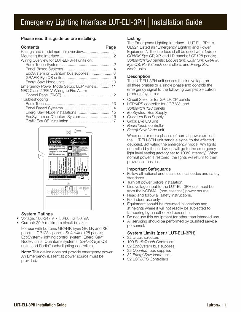
System Ratings• Voltage:100-347V 50/60Hz30mA• Current:20Amaximumcircuitbreaker ForusewithLutron®:GRAFIK Eye®GP,LP,andXP
panels;LCP128TMpanels;Softswitch128panels;EcoSystem®lightingcontrolsystem;EnergiSavrNodeTM units;Quantum® systems;GRAFIK EyeQSunits,andRadioTouch®lightingcontrollers.
Note:Thisdevicedoesnotprovideemergencypower.AnEmergency(Essential)powersourcemustbeprovided.
Please read this guide before installing.
Contents Page Ratingsandmodelnumberoverview............................1 MountingtheInterface.................................................2 WiringOverviewforLUT-ELI-3PHunitson: RadioTouchSystems...............................................2 Panel-BasedSystems..............................................4 EcoSystemorQuantumbussupplies.......................8 GRAFIKEyeQSunits...............................................9
EnergiSavrNodeunits..........................................10 EmergencyPowerModeSetup:LCPPanels..............11 NECClass2/PELVWiringtoFireAlarm
ControlPanel(FACP).............................................12 Troubleshooting RadioTouch ............................................................13 PanelBasedSystems............................................14 EnergiSavrNode Installations................................15 EcoSystemorQuantumSystem............................16 GrafikEyeQSInstallation.......................................17
Listing TheEmergencyLightingInterface–LUT-ELI-3PHis
UL924Listedas“EmergencyLightingandPowerEquipment”.Theinterfaceshallbeusedwith:Lutron GRAFIK EyeGP,XP,andLPpanels;LCP128panels;Softswitch128panels;EcoSystem;Quantum;GRAFIK Eye QS,RadioTouchcontrollers,andEnergi Savr Nodeunits.
Description TheLUT-ELI-3PHunitsensesthelinevoltageon
allthreephasesorasinglephaseandcontrolstheemergencysignaltothefollowingcompatibleLutronproducts/systems:
• CircuitSelectorforGP,LP,XPpanels• LCP/XPScontrollerforLCP128,and Softswitch 128panels• EcoSystemBusSupply• QuantumBusSupply• Grafik EyeQSunit• RadioTouchcontroller• Energi Savr Nodeunit Whenoneormorephasesofnormalpowerarelost,
theLUT-ELI-3PHunitsendsasignaltotheaffecteddevice(s),activatingtheemergencymode.Anylightscontrolledbythesedeviceswillgototheemergencylightlevelsetting(factorysetto100%intensity).Whennormalpowerisrestored,thelightswillreturntotheirpreviousintensities.
Important Safeguards• Followallnationalandlocalelectricalcodesandsafety
standards.• Turnoffpowerbeforeinstallation.• LinevoltageinputtotheLUT-ELI-3PHunitmustbe
fromtheNORMAL(non-essential)powersource.• Readandfollowallsafetyinstructions.• Forindooruseonly.• Equipmentshouldbemountedinlocationsand
atheightswhereitwillnotreadilybesubjectedtotamperingbyunauthorizedpersonnel.
• Donotusethisequipmentforotherthanintendeduse.• Allservicingshouldbeperformedbyqualifiedservice
personnel.
System Limits (per / LUT-ELI-3PH)• 32circuitselectors• 100RadioTouchControllers• 32EcoSystembussupplies• 32Quantumbussupplies• 32Energi Savr Nodeunits• 32LCP/XPSControllers
Emergency Lighting Interface LUT-ELI-3PH | Installation Guide
Lutron® | 2 LUT-ELI-3PH Installation Guide
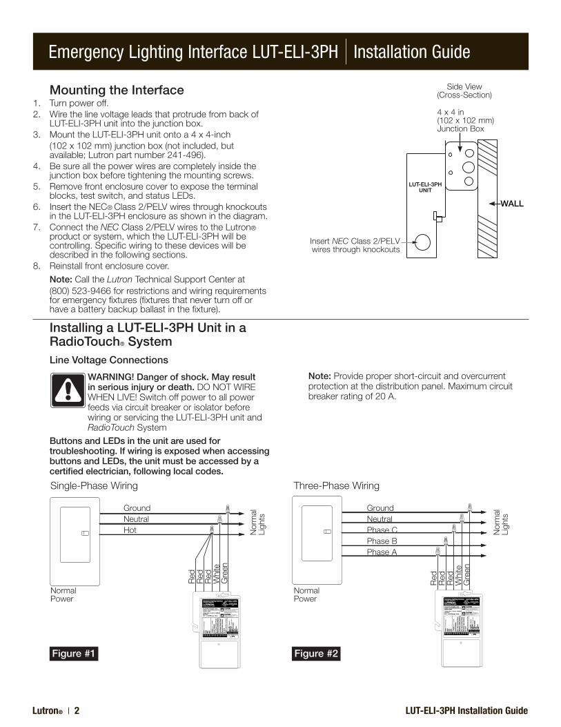
Mounting the Interface1. Turnpoweroff.2. Wirethelinevoltageleadsthatprotrudefrombackof
LUT-ELI-3PHunitintothejunctionbox.3. MounttheLUT-ELI-3PHunitontoa4x4-inch (102x102mm)junctionbox(notincluded,but
available;Lutronpartnumber241-496).4. Besureallthepowerwiresarecompletelyinsidethe
junctionboxbeforetighteningthemountingscrews.5. Removefrontenclosurecovertoexposetheterminal
blocks,testswitch,andstatusLEDs.6. InserttheNEC®Class2/PELVwiresthroughknockouts
intheLUT-ELI-3PHenclosureasshowninthediagram.7. ConnecttheNECClass2/PELVwirestotheLutron®
productorsystem,whichtheLUT-ELI-3PHwillbecontrolling.Specificwiringtothesedeviceswillbedescribedinthefollowingsections.
8. Reinstallfrontenclosurecover. Note:CalltheLutronTechnicalSupportCenterat (800)523-9466forrestrictionsandwiringrequirements
foremergencyfixtures(fixturesthatneverturnofforhaveabatterybackupballastinthefixture).
InsertNECClass2/PELVwiresthroughknockouts
4x4in(102x102mm)JunctionBox
SideView(Cross-Section)
Installing a LUT-ELI-3PH Unit in a RadioTouch® SystemLine Voltage Connections
WARNING! Danger of shock. May result in serious injury or death.DONOTWIREWHENLIVE!SwitchoffpowertoallpowerfeedsviacircuitbreakerorisolatorbeforewiringorservicingtheLUT-ELI-3PHunitandRadioTouchSystem
Buttons and LEDs in the unit are used for troubleshooting. If wiring is exposed when accessing buttons and LEDs, the unit must be accessed by a certified electrician, following local codes.
Note: Providepropershort-circuitandovercurrentprotectionatthedistributionpanel.Maximumcircuitbreakerratingof20A.
Single-PhaseWiring
GroundNeutralHot
NormalPower
Normal
Ligh
ts
Red
Red
Red
White
Green
Three-PhaseWiring
GroundNeutralPhaseCPhaseBPhaseA
NormalPower
Normal
Ligh
ts
Red
Red
Red
White
Green
WALL
LUT-ELI-3PHUNIT
Figure #1 Figure #2
Emergency Lighting Interface LUT-ELI-3PH | Installation Guide
LUT-ELI-3PH Installation Guide Lutron® | 3
1 2 3 4 5 6 7 8 9 10 11 12 13 14 15 16CLASS 2 LOW VOLTAGE WIRING
1 2 3 4 5 Power Status Program Burn-In1 2 3
3 7 8 9 10 11 12 13 14 15 16CLASS 2 LOW VOLTAGE WIRING
1 2 3 4 5 Power Status Program Burn-In1 2 3
4 5 61 2
´FACP´N
/C
CONTA
CTS
´FACP´N
/O
CONTA
CTS
CLASS2LOWVOLTAGEWIRING
GND
SENSE
DRAIN
MUX
MUX
+24
VFW
COMMO
N
NOTUSED
LED1
LED3
LED2
RADIOTO
UCH
PHASE
FACF
S1
TEST
12 11 10 9 8 7 6 5 4 3 2 112 11 10 9 8 7 6 5 4 3 2 1
RadioTouch TM
Coopersburg,PA18036USA
RTA-RX-F-SCLISTED243CInd.Cont.Eq.
1 2 3 4 5 6 7 8 9 10 11 12 13 14 15 16
Occ
.Com
Occ
Sig
24V
CirCom
CCO1
CCO2
CCO3
CCO4
CCO5
CCOCom+ _
PELV
(Class2:U
SA)
PWR STAT PROG 100Hr/100%
®
PSSig
P/N
500
-106
34©
2006
LutronElectronicsCo.,Inc
.
1 2 3 4 5
ON
PowerWiringCableadodePoderCâblaged'alimentation
DistributionPanelPaneldeDistribuciónPanneaudeDistribution
Ground/Tierra/Terre
Neutral/Neutro/Neutre
Black/Negro/Noir
Green/V erde/Vert
White/Blanco/Blanc
Red/Rojo/RougeOR
Orange/Anaranjado/Orange*
SwitchedHot/InterruptorVivo/CourantCommuté
DimmedHot/AtenuadorVivo/CourantTamisé*
Dimmed Hot is for use only with Lutron Hi-Lume FDB-series or Eco-10 ECO-series dimming ballasts.
El Atenuador V ivo es para ser utilizado únicamente con las series de balastosde atenuaci ón Hi-Lume FDB o Eco-10 ECO de Lutron.Courant T amisé doit être utilisé seulement avec le Hi-Lume FDB-series ou avecle ballast de gradation Eco-10 ECO-series de Lutron.
P/N 500-10634
***
Hot/Vivo/Chargé
For 120 V~ use black wire, cap red. For 277 V~ use red wire, cap black.
Blue/Bleu/Azul
120V277V
*
USA,Canada 1-800-523-9466Mexico 1-888-235-2910
®
www .lutron.com
RTA-R X-F-SC
15V
CONFIGURACIONESREGLAGESSETTINGS
RefertotheInstallersGuideformoredetailedinstructions.ConsultelaGuíadeInstaladoresparainformaciónmásdetallada.RéférerauGuided’installationpourplusderenseignementsdétaillés.
120/277V60Hz16AMax.
0-10V
Red&Black/Rojo&Negro/Rouge&Noir
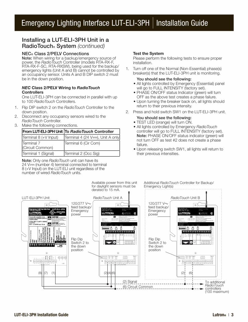
LUT-ELI-3PHUnit RadioTouchUnitA RadioTouchUnitB
120/277V feedbackup/Emergencypower
120/277V feedbackup/Emergencypower
FlipDipSwitch2tothedownposition
FlipDipSwitch2tothedownposition
(2)Signal(6)CircuitCommon
ToadditionalRadioTouchcontrollers(100maximum)
AdditionalRadioTouchControllerforBackup/EmergencyLight(s)
Availablepowerfromthisunitfordaylightsensorsmustbederatedto15mA.
(8) (2)(7) (4)(1) (6)
Installing a LUT-ELI-3PH Unit in a RadioTouch® System (continued)NEC® Class 2/PELV ConnectionsNote: Whenwiringforabackup/emergencysourceofpower,theRadioTouchController(modelsRTA-RX-F,RTA-RX-F-SC,RTA-RXSW),beingusedforthebackup/emergencylights(UnitAandB)cannotbecontrolledbyanoccupancysensor.UnitsAandBDIPswitch2mustbeinthedownposition.
NEC Class 2/PELV Wiring to RadioTouch ControllersOneLUT-ELI-3PHcanbeconnectedinparallelwithupto100RadioTouchControllers.
1. FlipDIPswitch2ontheRadioTouchControllertothedownposition.
2. DisconnectanyoccupancysensorswiredtotheRadioTouchController.
3. Makethefollowingconnections.
From LUT-ELI-3PH Unit To RadioTouch ControllerTerminal8(+VInput) Terminal4(24V ),UnitAonlyTerminal7(CircuitCommon)
Terminal6(CirCom)
Terminal1(Signal) Terminal2(OccSig)
Test the System Pleaseperformthefollowingteststoensureproper
installation.1. TurnoffoneoftheNormal(Non-Essential)phase(s)
breaker(s)thattheLUT-ELI-3PHunitismonitoring. You should see the following: •AlllightscontrolledbyEmergency(Essential)panel
willgotoFULLINTENSITY(factoryset). •PHASEON/OFFstatusIndicator(green)willturn
OFFastheabovetestcreatesaphasefailure. •Uponturningthebreakerbackon,alllightsshould
returntotheirpreviousintensity.2. PressandholdswitchSW1ontheLUT-ELI-3PHunit. You should see the following: •TESTLED(orange)willturnON. •AlllightscontrolledbyEmergencyRadioTouch
controllerwillgotoFULLINTENSITY(factoryset). Note: PHASEON/OFFstatusindicator(green)will
notturnOFFastest#2doesnotcreateaphasefailure.
•UponreleasingswitchSW1,alllightswillreturntotheirpreviousintensities.
Note:OnlyoneRadioTouchunitcanhaveits24V (number4)terminalconnectedtoterminal8(+VInput)ontheLUT-ELIunitregardlessofthenumberofwiredRadioTouchunits.
(2) (6)
Emergency Lighting Interface LUT-ELI-3PH | Installation Guide
Lutron® | 4 LUT-ELI-3PH Installation Guide
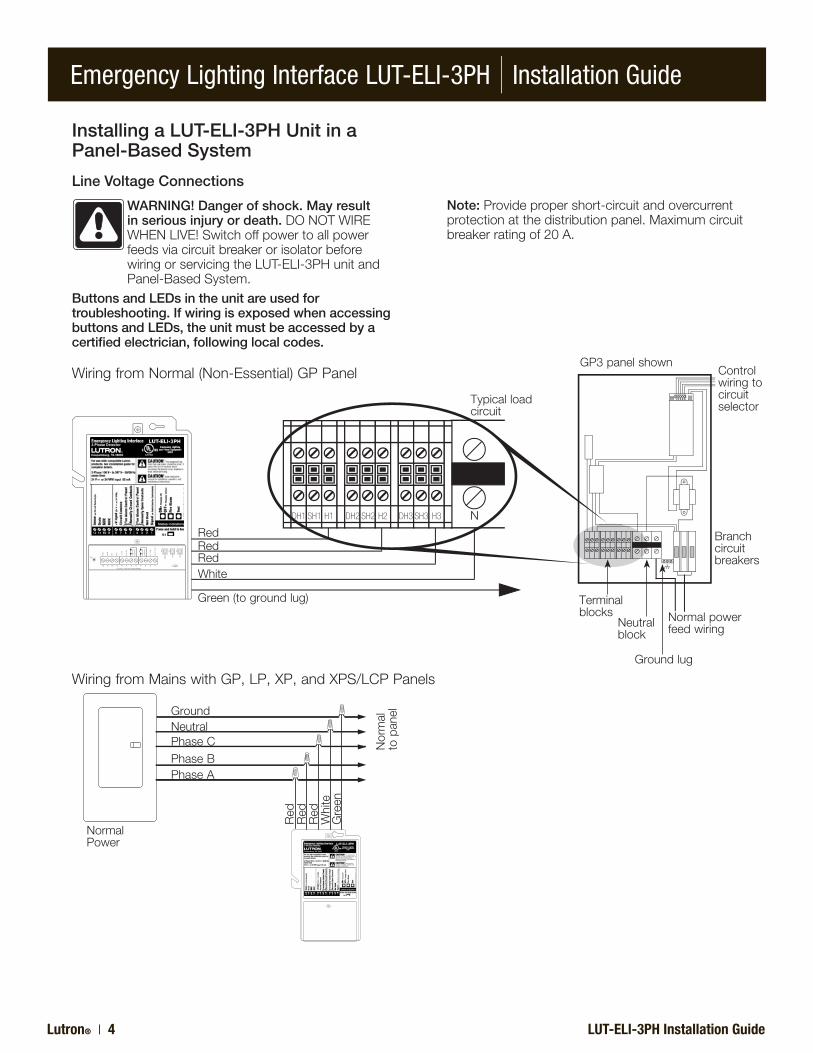
Installing a LUT-ELI-3PH Unit in a Panel-Based System
Line Voltage Connections
WARNING! Danger of shock. May result in serious injury or death.DONOTWIREWHENLIVE!SwitchoffpowertoallpowerfeedsviacircuitbreakerorisolatorbeforewiringorservicingtheLUT-ELI-3PHunitandPanel-BasedSystem.
Buttons and LEDs in the unit are used for troubleshooting. If wiring is exposed when accessing buttons and LEDs, the unit must be accessed by a certified electrician, following local codes.
Note: Providepropershort-circuitandovercurrentprotectionatthedistributionpanel.Maximumcircuitbreakerratingof20A.
WiringfromMainswithGP,LP,XP,andXPS/LCPPanels
PhaseA
NormalPower
Normal
topan
el
Red
Red
Red
White
Green
PhaseBPhaseCNeutralGround
WiringfromNormal(Non-Essential)GPPanel
DH1 SH1 H1 DH2 SH2 H2 DH3 SH3 H3
´FACP´N
/C
CONTA
CTS
´FACP´N
/O
CONTA
CTS
12 11 10 9 8 7 6 5 4 3 2 1CLASS2LOWVOLTAGEWIRING
GND
SENS
E
DRAIN
MUX
MUX
+24
VFW
COMMO
N
NOTUSED
LED1
LED3
LED2
RADIOTO
UCH
PHASE
FACF
S1
TEST
RedRedRedWhite
Green(togroundlug)
Typicalloadcircuit
Controlwiringtocircuitselector
GP3panelshown
Branchcircuitbreakers
Normalpowerfeedwiring
Terminalblocks
Neutralblock
Groundlug
N
Emergency Lighting Interface LUT-ELI-3PH | Installation Guide
LUT-ELI-3PH Installation Guide Lutron® | 5
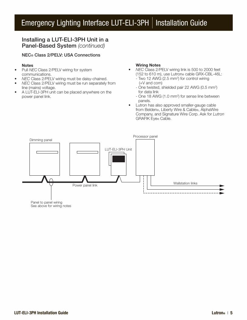
Installing a LUT-ELI-3PH Unit in a Panel-Based System (continued)
NEC® Class 2/PELV: USA Connections
Notes• PullNECClass2/PELVwiringforsystem
communications.• NECClass2/PELVwiringmustbedaisy-chained.• NECClass2/PELVwiringmustberunseparatelyfrom
line(mains)voltage.• ALUT-ELI-3PHunitcanbeplacedanywhereonthe powerpanellink.
Wiring Notes• NECClass2/PELVwiringlinkis500to2000feet (152to610m),useLutron®cableGRX-CBL-46L: -Two12AWG(2.5mm2)forcontrolwiring (+Vandcom) -Onetwisted,shieldedpair22AWG(0.5mm2)
fordatalink -One18AWG(1.0mm2)forsenselinebetween
panels.• Lutronhasalsoapprovedsmaller-gaugecable
fromBelden®,LibertyWire&Cable®,AlphaWireCompany,andSignatureWireCorp.AskforLutronGRAFIKEye®Cable.
PaneltopanelwiringSeeaboveforwiringnotes
Dimmingpanel
Powerpanellink
LUT-ELI-3PHUnit
Processorpanel
Wallstationlinks
Emergency Lighting Interface LUT-ELI-3PH | Installation Guide
Lutron® | 6 LUT-ELI-3PH Installation Guide
´FACP´N
/C
CONTA
CTS
´FACP´N
/O
CONTA
CTS
CLASS2LOWVOLTAGEWIRING
GND
SENS
E
DRAIN
MUX
MUX
+24
VFW
COMMON
NOTUSED
LED1
LED3
LED2
RADIOTO
UCH
PHASE
FACF
S1
TEST
DataAOK Power DataBOK
1 2 3 4 D 5
Com
mon
Com
mon
+24
VFW
Sen
se
MUX
MUX
Drain
Drain
MUX
MUX
Circuit
1
2
Link
A
1
23,4
5
1
2
3,4
DataAOK Power DataBOK
1 2 3 4 D 5 C D
Com
mon
Com
mon
+24
VFW
Sen
se
MUX
MUX
Drain
Drain
MUX
MUX
Circuit
1
2
1 2 3 4 D 5
SELECT CIRCUIT SELECT CIRCUIT
Link
BLink
ALink
B1 2 3 4 D 5 C D
12 11 10 9 8 7 6 5 4 3 2 112 11 10 9 8 7 6 5 4 3 2 1
Shield/Drain
Tolightingcontrolsorprocessors
ControlWiring:(2)12AWG(2.5mm2)1:Common2:24V
DataLink:(1)shielded,twistedpair18AWG(1.0mm2)3:MUX4:MUX
Sense:(1)18AWG(1.0mm2)5:Senseline
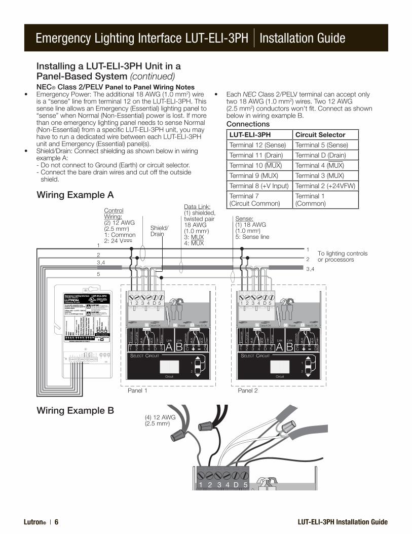
Installing a LUT-ELI-3PH Unit in a Panel-Based System (continued)NEC® Class 2/PELV Panel to Panel Wiring Notes
• EmergencyPower:Theadditional18AWG(1.0mm2)wireisa“sense”linefromterminal12ontheLUT-ELI-3PH.ThissenselineallowsanEmergency(Essential)lightingpanelto“sense”whenNormal(Non-Essential)powerislost.IfmorethanoneemergencylightingpanelneedstosenseNormal(Non-Essential)fromaspecificLUT-ELI-3PHunit,youmayhavetorunadedicatedwirebetweeneachLUT-ELI-3PHunitandEmergency(Essential)panel(s).
• Shield/Drain:ConnectshieldingasshownbelowinwiringexampleA:
-DonotconnecttoGround(Earth)orcircuitselector. -Connectthebaredrainwiresandcutofftheoutside
shield.
ConnectionsLUT-ELI-3PH Circuit Selector
Terminal12(Sense) Terminal5(Sense)
Terminal11(Drain) TerminalD(Drain)
Terminal10(MUX) Terminal4(MUX)
Terminal9(MUX) Terminal3(MUX)
Terminal8(+VInput) Terminal2(+24VFW)
Terminal7(CircuitCommon)
Terminal1(Common)
Panel1 Panel2
Data A OK Data B OKPower OK
1 2 3 4 5D
2
1
Circuit
AB
Com
mon
24VFW
MUX
MUX
Drain
Sen
se
Com
m
Drain
MUX
MUX
C1 2 3 4 D 5 D
Link Link
SELECT CIRCUIT
SELECT VALUEVIEW VALUE
(4)12AWG(2.5mm2)
• EachNECClass2/PELVterminalcanacceptonlytwo18AWG(1.0mm2)wires.Two12AWG
(2.5mm2)conductorswon'tfit.ConnectasshownbelowinwiringexampleB.
Wiring Example A
Wiring Example B
Emergency Lighting Interface LUT-ELI-3PH | Installation Guide
LUT-ELI-3PH Installation Guide Lutron® | 7
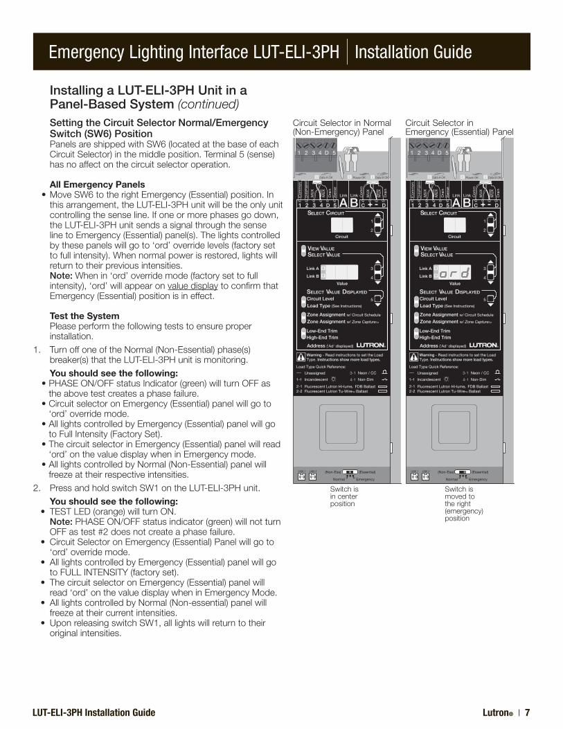
Installing a LUT-ELI-3PH Unit in a Panel-Based System (continued)
Setting the Circuit Selector Normal/Emergency Switch (SW6) Position
PanelsareshippedwithSW6(locatedatthebaseofeachCircuitSelector)inthemiddleposition.Terminal5(sense)hasnoaffectonthecircuitselectoroperation.
All Emergency Panels •MoveSW6totherightEmergency(Essential)position.In
thisarrangement,theLUT-ELI-3PHunitwillbetheonlyunitcontrollingthesenseline.Ifoneormorephasesgodown,theLUT-ELI-3PHunitsendsasignalthroughthesenselinetoEmergency(Essential)panel(s).Thelightscontrolledbythesepanelswillgoto‘ord’overridelevels(factorysettofullintensity).Whennormalpowerisrestored,lightswillreturntotheirpreviousintensities.
Note: Whenin‘ord’overridemode(factorysettofullintensity),‘ord’willappearonvaluedisplaytoconfirmthatEmergency(Essential)positionisineffect.
Test the System Pleaseperformthefollowingteststoensureproper
installation.1. TurnoffoneoftheNormal(Non-Essential)phase(s)
breaker(s)thattheLUT-ELI-3PHunitismonitoring. You should see the following: •PHASEON/OFFstatusIndicator(green)willturnOFFas
theabovetestcreatesaphasefailure. •CircuitselectoronEmergency(Essential)panelwillgoto
‘ord’overridemode. •AlllightscontrolledbyEmergency(Essential)panelwillgo
toFullIntensity(FactorySet). •ThecircuitselectorinEmergency(Essential)panelwillread
‘ord’onthevaluedisplaywheninEmergencymode. •AlllightscontrolledbyNormal(Non-Essential)panelwill
freezeattheirrespectiveintensities.2. PressandholdswitchSW1ontheLUT-ELI-3PHunit. You should see the following: • TESTLED(orange)willturnON. Note: PHASEON/OFFstatusindicator(green)willnotturn
OFFastest#2doesnotcreateaphasefailure. • CircuitSelectoronEmergency(Essential)Panelwillgoto
‘ord’overridemode. • AlllightscontrolledbyEmergency(Essential)panelwillgo
toFULLINTENSITY(factoryset). • ThecircuitselectoronEmergency(Essential)panelwill
read‘ord’onthevaluedisplaywheninEmergencyMode. • AlllightscontrolledbyNormal(Non-essential)panelwill
freezeattheircurrentintensities. • UponreleasingswitchSW1,alllightswillreturntotheir
originalintensities.
DataAOK DataBOKPowerOK
1 2 3 4 5D
Load Type (See Instructions)
High-End Trim
Circuit Level
Low-End Trim
5
4
3
Value
Link A
Link B
2
1
Circuit
A B
Com
mon
24V
FW
MU
X
MU
X
Dra
inS
ense
Com
m
Dra
in
MU
X
MU
X
C1 2 3 4 D 5 D
Link Link
1-1
2-12-2
3-1
4-1Incandescent
Neon / CC
Non-Dim
--- Unassigned
Fluorescent Lutron Tu-WireTM Ballast
Address ('Ad' displayed)
Zone Assignment w/ Circuit Schedule
Zone Assignment w/ Zone CaptureTM
Warning - Read instructions to set the LoadType. Instructions show more load types.
Load Type Quick Reference:
SELECT CIRCUIT
SELECT VALUEVIEW VALUE
SELECT VALUE DISPLAYED
Normal Emergency
(Essential)(Non-Ess)
Fluorescent Lutron Hi-lume R FDB Ballast
LINK 1 LINK 2
CircuitSelectorinNormal(Non-Emergency)Panel
CircuitSelectorinEmergency(Essential)Panel
Switchisincenterposition
Switchismovedtotheright(emergency)position
Emergency Lighting Interface LUT-ELI-3PH | Installation Guide
Lutron® | 8 LUT-ELI-3PH Installation Guide
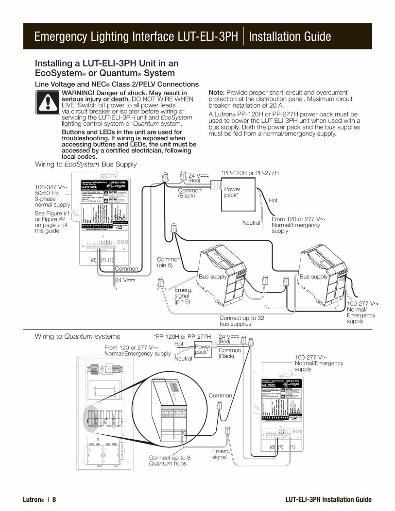
Installing a LUT-ELI-3PH Unit in an EcoSystem® or Quantum® SystemLine Voltage and NEC® Class 2/PELV Connections
WARNING! Danger of shock. May result in serious injury or death.DONOTWIREWHENLIVE!SwitchoffpowertoallpowerfeedsviacircuitbreakerorisolatorbeforewiringorservicingtheLUT-ELI-3PHunitandEcoSystemlightingcontrolsystemorQuantumsystem.Buttons and LEDs in the unit are used for troubleshooting. If wiring is exposed when accessing buttons and LEDs, the unit must be accessed by a certified electrician, following local codes.
Note: Providepropershort-circuitandovercurrentprotectionatthedistributionpanel.Maximumcircuitbreakerinstallationof20A.ALutron®PP-120HorPP-277HpowerpackmustbeusedtopowertheLUT-ELI-3PHunitwhenusedwithabussupply.Boththepowerpackandthebussuppliesmustbefedfromanormal/emergencysupply.
´FACP´N
/C
CONTA
CTS
´FACP´N
/O
CONTA
CTS
CLASS2LOWVOLTAGEWIRING
GND
SENSE
DRAIN
MUX
MUX
+24
VFW
COMMO
N
NOTUSED
LED1
LED3
LED2
RADIOTO
UCH
PHASE
FACF
S1
TEST
E2E1
12
34
56
78
E2E1
EM C
12 11 10 9 8 7 6 5 4 3 2 112 11 10 9 8 7 6 5 4 3 2 1
24V(Red)
Common(Black)
Hot
Neutral
From120or277VNormal/Emergencysupply
Common
Emerg.signalConnectupto8
Quantumhubs
100-277V Normal/Emergencysupply
Powerpack*
WiringtoQuantumsystems *PP-120HorPP-277H
WiringtoEcoSystemBusSupply
´FA
CP
´ N/C
CO
NTA
CTS
´FA
CP
´ N/O
CO
NTA
CTS
12 11 10 9 8 7 6 5 4 3 2 1CLASS 2 LOW VOLTAGE WIRING
GND
SE
NS
E
DR
AIN
MU
X
MU
X
+24
VFW
CO
MM
ON
NO
T U
SE
D
LED
1
LED
3
LED
2
RA
DIO
TOU
CH
PH
AS
E
FAC
F
S1
TES
T
100-347V 50/60Hz3-phasenormalsupply
SeeFigure#1orFigure#2onpage2ofthisguide.
Common
24V
24V(Red)
Common(Black)
Common(pin5)
Emerg.signal(pin6)
Hot
Neutral
Powerpack*
From120or277VNormal/Emergencysupply
Bussupply Bussupply
Connectupto32bussupplies
100-277V Normal/Emergencysupply
*PP-120HorPP-277H
(8) (7) (1)
(8) (7) (1)
Emergency Lighting Interface LUT-ELI-3PH | Installation Guide
LUT-ELI-3PH Installation Guide Lutron® | 9
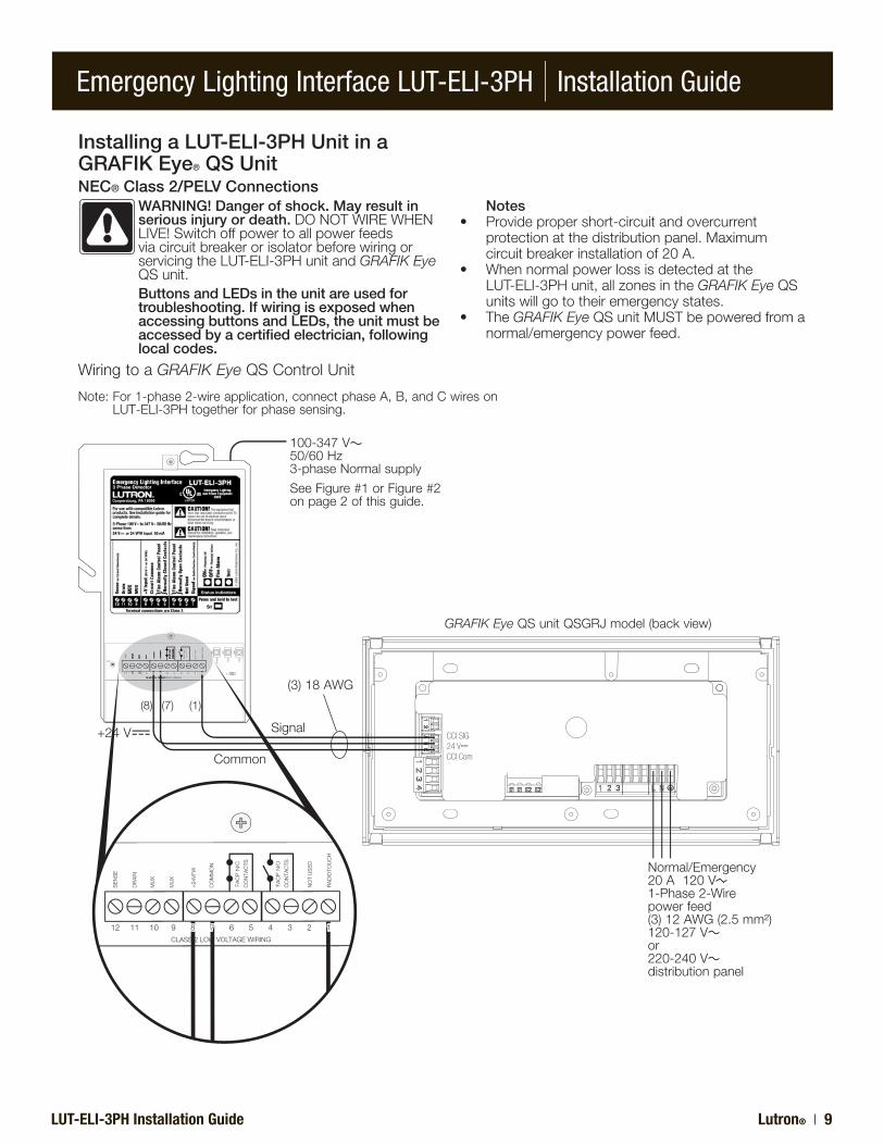
Installing a LUT-ELI-3PH Unit in a GRAFIK Eye® QS UnitNEC® Class 2/PELV Connections
WARNING! Danger of shock. May result in serious injury or death.DONOTWIREWHENLIVE!SwitchoffpowertoallpowerfeedsviacircuitbreakerorisolatorbeforewiringorservicingtheLUT-ELI-3PHunitandGRAFIK EyeQSunit.Buttons and LEDs in the unit are used for troubleshooting. If wiring is exposed when accessing buttons and LEDs, the unit must be accessed by a certified electrician, following local codes.
WiringtoaGRAFIK EyeQSControlUnit
Notes • Providepropershort-circuitandovercurrent
protectionatthedistributionpanel.Maximumcircuitbreakerinstallationof20A.
• Whennormalpowerlossisdetectedatthe LUT-ELI-3PHunit,allzonesintheGRAFIK EyeQS
unitswillgototheiremergencystates.• TheGRAFIK EyeQSunitMUSTbepoweredfroma
normal/emergencypowerfeed.
Note:For1-phase2-wireapplication,connectphaseA,B,andCwiresonLUT-ELI-3PHtogetherforphasesensing.
´FACP´N
/O
CONTA
CTS
TAGEWIRING
GND
SENSE
NOTUSED
LED1
LED3
LED2
RADIOTO
UCH
PHASE
FACF
S1
TEST
12 9 8 7 6 5 4 3 2 1
´FACP´
CP´N
/O
CCONTA
CTS
TAGEWIRING
SE
NS
E
NOTUS
ED
LED
RADIO
TOUCH
12 8 7 6 5 4 379 8 7 6 5 4 3 2 1
´FACP´N
/C
CONTA
CTS
´FACP´N
/O
CONTA
CTS
CLASS2LOWVOLTAGEWIRING
SENS
E
DRAIN
MUX
MUX
+24
VFW
COMMO
N
NOTUSED
LED3
RADIOTO
UCH
12 11 10 9 8 7 6 5 4 3 2 1
Signal+24V
Common
(3)18AWG
GRAFIK EyeQSunitQSGRJmodel(backview)
Normal/Emergency20A120V1-Phase2-Wirepowerfeed(3)12AWG(2.5mm²)120-127Vor220-240Vdistributionpanel
100-347V 50/60Hz3-phaseNormalsupply
SeeFigure#1orFigure#2onpage2ofthisguide.
CCI SIG24 VCCI Com
(8) (7) (1)
Emergency Lighting Interface LUT-ELI-3PH | Installation Guide
Lutron® | 10 LUT-ELI-3PH Installation Guide
´FA
CP
´ N/C
CO
NTA
CTS
´FA
CP
´ N/O
CO
NTA
CTS
12 11 10 9 8 7 6 5 4 3 2 112 11 10 9 8 7 6 5 4 3 2 1CLASS 2 LOW VOLTAGE WIRING
GND
SE
NS
E
DR
AIN
MU
X
MU
X
+24
VFW
CO
MM
ON
NO
T U
SE
D
LED
1
LED
3
LED
2
RA
DIO
TOU
CH
PH
AS
E
FAC
F
S1
TES
T
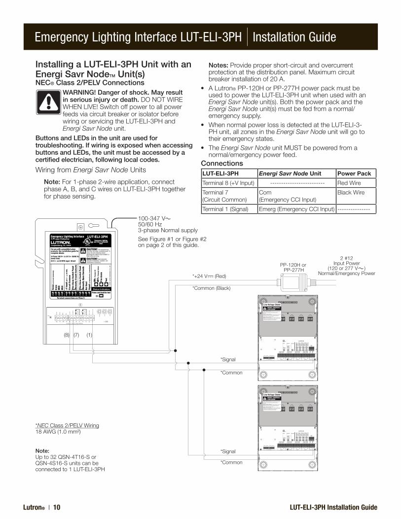
Installing a LUT-ELI-3PH Unit with an Energi Savr NodeTM Unit(s)NEC® Class 2/PELV Connections
WARNING! Danger of shock. May result in serious injury or death.DONOTWIREWHENLIVE!SwitchoffpowertoallpowerfeedsviacircuitbreakerorisolatorbeforewiringorservicingtheLUT-ELI-3PHandEnergi Savr Nodeunit.
Buttons and LEDs in the unit are used for troubleshooting. If wiring is exposed when accessing buttons and LEDs, the unit must be accessed by a certified electrician, following local codes.
Notes: Providepropershort-circuitandovercurrentprotectionatthedistributionpanel.Maximumcircuitbreakerinstallationof20A.
• ALutron®PP-120HorPP-277HpowerpackmustbeusedtopowertheLUT-ELI-3PHunitwhenusedwithanEnergi Savr Nodeunit(s).BoththepowerpackandtheEnergi Savr Nodeunit(s)mustbefedfromanormal/emergencysupply.
• WhennormalpowerlossisdetectedattheLUT-ELI-3-PHunit,allzonesintheEnergi Savr Nodeunitwillgototheiremergencystates.
• TheEnergi Savr NodeunitMUSTbepoweredfromanormal/emergencypowerfeed.
WiringfromEnergi Savr NodeUnits
Note: For1-phase2-wireapplication,connectphaseA,B,andCwiresonLUT-ELI-3PHtogetherforphasesensing.
ConnectionsLUT-ELI-3PH Energi Savr Node Unit Power Pack
Terminal8(+VInput) ------------------------- RedWire
Terminal7(CircuitCommon)
Com(EmergencyCCIInput)
BlackWire
Terminal1(Signal) Emerg(EmergencyCCIInput) ---------------
*NECClass2/PELVWiring18AWG(1.0mm²)
Note:Upto32QSN-4T16-SorQSN-4S16-Sunitscanbeconnectedto1LUT-ELI-3PH
*Signal
*Common(Black)
*+24V (Red)
PP-120HorPP-277H
*Signal
*Common
*Common
2#12InputPower
(120or277V )Normal/EmergencyPower
(8) (7) (1)
100-347V 50/60Hz3-phaseNormalsupply
SeeFigure#1orFigure#2onpage2ofthisguide.
Emergency Lighting Interface LUT-ELI-3PH | Installation Guide
LUT-ELI-3PH Installation Guide Lutron® | 11
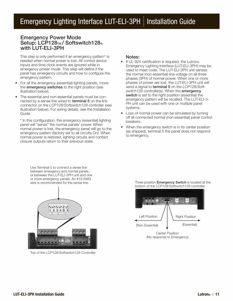
Emergency Power ModeSetup: LCP128TM / Softswitch128®
with LUT-ELI-3PH
Thisstepisonlyperformedifanemergencypattern*isneededwhennormalpowerislost.Allcontroldeviceinputsandtimeclockeventsareignoredwhileinemergencypowermode.Thisstepwilldefineifthepanelhasemergencycircuitsandhowtoconfiguretheemergencypattern.
•Foralltheemergency(essential)lightingpanels,movetheemergency switchestotherightposition(seeillustrationbelow).
•Theessentialandnon-essentialpanelsmustbecon-nectedbyasenselinewiredtoterminal 5onthelinkconnectorontheLCP128/Softswitch128controller(seeillustrationbelow).Forwiringdetails,seetheInstallationGuide.
*Inthisconfiguration,theemergency(essential)lightingpanelwill“sense”thenormalpanels’power.Whennormalpowerislost,theemergencypanelwillgototheemergencypattern(factorysettoallcircuitsOn).Whennormalpowerisrestored,lightingcircuitsandcontactclosureoutputsreturntotheirpreviousstate.
UseTerminal5toconnectasenselinebetweenemergencyandnormalpanels,orbetweentheLUT-ELI-3PHunitandoneormoreemergencypanels.An#18AWGwireisrecommendedforthesenseline. ThreepositionEmergency Switchislocatedatthe
bottomoftheLCP128/Softswitch128controller.
1 2 3 4 5D
TopoftheLCP128/Softswitch128Controller
LeftPosition RightPosition
(Non-Essential) (Essential)
CenterPosition(NoresponsetoEmergency)
Notes:•IfUL924certificationisrequired,theLutron®
EmergencyLightingInterface(LUT-ELI-3PH)maybeusedtomeetcode.TheLUT-ELI-3PHunitsensesthenormal(non-essential)linevoltageonallthreephases(3PH)ofnormalpower.Whenoneormorephasesofpowerarelost,theLUT-ELI-3PHunitwillsendasignaltoterminal 5ontheLCP128/Soft-switch128controller(s).Whentheemergency switchissettotherightposition(essential)theemergencypatternwillberecalled.TheLUT-ELI-3-PHunitcanbeusedwithoneormultiplepanelsystems.
•Lossofnormalpowercanbesimulatedbyturningoffallconnectednormal(non-essential)panelcontrolbreakers.
•Whentheemergencyswitchisinitscenterposition(asshipped),terminal5thepaneldoesnotrespondtoemergency.
Emergency Lighting Interface LUT-ELI-3PH | Installation Guide
Lutron® | 12 LUT-ELI-3PH Installation Guide
´FACP´N
/C
CONTA
CTS
´FACP´N
/O
CONTA
CTS
CLASS2LOWVOLTAGEWIRING
GND
SENSE
DRAIN
MUX
MUX
+24
VFW
COMMO
N
NOTUSED
LED1
LED3
LED2
RADIOTO
UCH
PHASE
FACF
S1
TEST
12 11 10 9 8 7 6 5 4 3 2 112 11 10 9 8 7 6 5 4 3 2 1
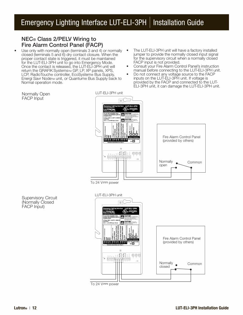
NormallyOpenFACPInput
LUT-ELI-3PHunit
To24V power
FireAlarmControlPanel(providedbyothers)
CommonNormallyopen
NEC® Class 2/PELV Wiring to Fire Alarm Control Panel (FACP)
• Useonlywithnormallyopen(terminals3and4)ornormallyclosed(terminals5and6)drycontactclosure.Whenthepropercontactstateistriggered,itmustbemaintainedfortheLUT-ELI-3PHunittogointoEmergencyMode.Oncethecontactisreleased,theLUT-ELI-3PHunitwillreturntheGRAFIKSystemsTMGP,LP,XPpanels,XPS,LCP,RadioTouch®controller,EcoSystem®BusSupply,EnergiSavrNodeTMunit,orQuantum®BusSupplybacktoNormaloperationmode.
• TheLUT-ELI-3PHunitwillhaveafactoryinstalledjumpertoprovidethenormallyclosedinputsignalforthesupervisorycircuitwhenanormallyclosedFACPinputisnotprovided.
• ConsultyourFireAlarmControlPanel’sinstructionmanualbeforeconnectingtotheLUT-ELI-3PHunit.
• DonotconnectanyvoltagesourcetotheFACPinputsontheLUT-ELI-3PHunit.IfvoltageisprovidedbytheFACPandconnectedtotheLUT-ELI-3PHunit,itcandamagetheLUT-ELI-3PHunit.
´FACP´N
/C
CONTA
CTS
´FACP´N
/O
CONTA
CTS
CLASS2LOWVOLTAGEWIRING
GND
SENSE
DRAIN
MUX
MUX
+24
VFW
COMMO
N
NOTUSED
LED1
LED3
LED2
RADIOTO
UCH
PHASE
FACF
S1
TEST
12 11 10 9 8 7 6 5 4 3 2 112 11 10 9 8 7 6 5 4 3 2 1
SupervisoryCircuit(NormallyClosedFACPInput)
LUT-ELI-3PHunit
To24V power
FireAlarmControlPanel(providedbyothers)
CommonNormallyclosed
Emergency Lighting Interface LUT-ELI-3PH | Installation Guide
LUT-ELI-3PH Installation Guide Lutron® | 13
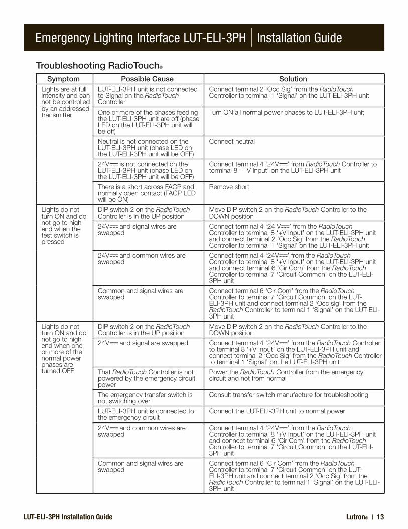
Troubleshooting RadioTouch®
Symptom Possible Cause SolutionLightsareatfullintensityandcannotbecontrolledbyanaddressedtransmitter
LUT-ELI-3PHunitisnotconnectedtoSignalontheRadioTouchController
Connectterminal2‘OccSig’fromtheRadioTouchControllertoterminal1‘Signal’ontheLUT-ELI-3PHunit
OneormoreofthephasesfeedingtheLUT-ELI-3PHunitareoff(phaseLEDontheLUT-ELI-3PHunitwillbeoff)
TurnONallnormalpowerphasestoLUT-ELI-3PHunit
NeutralisnotconnectedontheLUT-ELI-3PHunit(phaseLEDontheLUT-ELI-3PHunitwillbeOFF)
Connectneutral
24V isnotconnectedontheLUT-ELI-3PHunit(phaseLEDontheLUT-ELI-3PHunitwillbeOFF)
Connectterminal4‘24V ’fromRadioTouchControllertoterminal8‘+VInput’ontheLUT-ELI-3PHunit
ThereisashortacrossFACPandnormallyopencontact(FACPLEDwillbeON)
Removeshort
LightsdonotturnONanddonotgotohighendwhenthetestswitchispressed
DIPswitch2ontheRadioTouchControllerisintheUPposition
MoveDIPswitch2ontheRadioTouchControllertotheDOWNposition
24V andsignalwiresareswapped
Connectterminal4‘24V ’fromtheRadioTouchControllertoterminal8‘+VInput’ontheLUT-ELI-3PHunitandconnectterminal2‘OccSig’fromtheRadioTouchControllertoterminal1‘Signal’ontheLUT-ELI-3PHunit
24V andcommonwiresareswapped
Connectterminal4‘24V ’fromtheRadioTouchControllertoterminal8‘+VInput’ontheLUT-ELI-3PHunitandconnectterminal6‘CirCom’fromtheRadioTouchControllertoterminal7‘CircuitCommon’ontheLUT-ELI-3PHunit
Commonandsignalwiresareswapped
Connectterminal6‘CirCom’fromtheRadioTouchControllertoterminal7‘CircuitCommon’ontheLUT-ELI-3PHunitandconnectterminal2‘Occsig’fromtheRadioTouchControllertoterminal1‘Signal’ontheLUT-ELI-3PHunit
LightsdonotturnONanddonotgotohighendwhenoneormoreofthenormalpowerphasesareturnedOFF
DIPswitch2ontheRadioTouchControllerisintheUPposition
MoveDIPswitch2ontheRadioTouchControllertotheDOWNposition
24V andsignalareswapped Connectterminal4‘24V ’fromtheRadioTouchControllertoterminal8‘+VInput’ontheLUT-ELI-3PHunitandconnectterminal2‘OccSig’fromtheRadioTouchControllertoterminal1‘Signal’ontheLUT-ELI-3PHunit
ThatRadioTouchControllerisnotpoweredbytheemergencycircuitpower
PowertheRadioTouchControllerfromtheemergencycircuitandnotfromnormal
Theemergencytransferswitchisnotswitchingover
Consulttransferswitchmanufacturefortroubleshooting
LUT-ELI-3PHunitisconnectedtotheemergencycircuit
ConnecttheLUT-ELI-3PHunittonormalpower
24V andcommonwiresareswapped
Connectterminal4‘24V ’fromtheRadioTouchControllertoterminal8‘+VInput’ontheLUT-ELI-3PHunitandconnectterminal6‘CirCom’fromtheRadioTouchControllertoterminal7‘CircuitCommon’ontheLUT-ELI-3PHunit
Commonandsignalwiresareswapped
Connectterminal6‘CirCom’fromtheRadioTouchControllertoterminal7‘CircuitCommon’ontheLUT-ELI-3PHunitandconnectterminal2‘OccSig’fromtheRadioTouchControllertoterminal1‘Signal’ontheLUT-ELI-3PHunit
Emergency Lighting Interface LUT-ELI-3PH | Installation Guide
Lutron® | 14 LUT-ELI-3PH Installation Guide
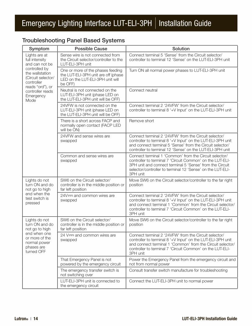
Troubleshooting Panel Based SystemsSymptom Possible Cause Solution
Lightsareatfullintensityandcannotbecontrolledbythewallstation(Circuitselector/controllerreads“ord”),orcontrollerreadsEmergencyMode
SensewireisnotconnectedfromtheCircuitselector/controllertotheLUT-ELI-3PHunit
Connectterminal5‘Sense’fromtheCircuitselector/controllertoterminal12‘Sense’ontheLUT-ELI-3PHunit
OneormoreofthephasesfeedingtheLUT-ELI-3PHunitareoff(phaseLEDontheLUT-ELI-3PHunitwillbeOFF)
TurnONallnormalpowerphasestoLUT-ELI-3PHunit
NeutralisnotconnectedontheLUT-ELI-3PHunit(phaseLEDontheLUT-ELI-3PHunitwillbeOFF)
Connectneutral
24VFWisnotconnectedontheLUT-ELI-3PHunit(phaseLEDontheLUT-ELI-3PHunitwillbeOFF)
Connectterminal2‘24VFW’fromtheCircuitselector/controllertoterminal8‘+VInput’ontheLUT-ELI-3PHunit
ThereisashortacrossFACPandnormallyopencontact(FACPLEDwillbeON)
Removeshort
24VFWandsensewiresareswapped
Connectterminal2‘24VFW’fromtheCircuitselector/controllertoterminal8‘+VInput’ontheLUT-ELI-3PHunitandconnectterminal5‘Sense’fromtheCircuitselector/controllertoterminal12‘Sense’ontheLUT-ELI-3PHunit
Commonandsensewiresareswapped
Connectterminal1‘Common’fromtheCircuitselector/controllertoterminal7‘CircuitCommon’ontheLUT-ELI-3PHunitandconnectterminal5‘Sense’fromtheCircuitselector/controllertoterminal12‘Sense’ontheLUT-ELI-3PHunit
LightsdonotturnONanddonotgotohighendwhenthetestswitchispressed
SW6ontheCircuitselector/controllerisinthemiddlepositionorfarleftposition
MoveSW6ontheCircuitselector/controllertothefarrightposition
24V andcommonwiresareswapped
Connectterminal2‘24VFW’fromtheCircuitselector/controllertoterminal8‘+VInput’ontheLUT-ELI-3PHunitandconnectterminal1‘Common’fromtheCircuitselector/controllertoterminal7‘CircuitCommon’ontheLUT-ELI-3PHunit
LightsdonotturnONanddonotgotohighendwhenoneormoreofthenormalpowerphasesareturnedOFF
SW6ontheCircuitselector/controllerisinthemiddlepositionorfarleftposition
MoveSW6ontheCircuitselector/controllertothefarrightposition
24V andcommonwiresareswapped
Connectterminal2‘24VFW’fromtheCircuitselector/controllertoterminal8‘+VInput’ontheLUT-ELI-3PHunitandconnectterminal1‘Common’fromtheCircuitselector/controllertoterminal7‘CircuitCommon’ontheLUT-ELI-3PHunit
ThatEmergencyPanelisnotpoweredbytheemergencycircuit
PowertheEmergencyPanelfromtheemergencycircuitandnotfromnormalpower
Theemergencytransferswitchisnotswitchingover
Consulttransferswitchmanufacturefortroubleshooting
LUT-ELI-3PHunitisconnectedtotheemergencycircuit
ConnecttheLUT-ELI-3PHunittonormalpower

Emergency Lighting Interface LUT-ELI-3PH | Installation Guide
LUT-ELI-3PH Installation Guide Lutron® | 15
Troubleshooting Energi Savr NodeTM InstallationsSymptom Possible Cause Solution
Lightsareatfullintensity.Unitwillnotrespondtolocalcontrolorinputsignals.
SignalwireisnotconnectedfromtheLUT-ELI-3PHunittotheEnergi Savr Nodeunit
Connect‘Emerg’terminalfromtheEnergi Savr Nodeunittoterminal1‘Signal’ontheLUT-ELI-3PHunit
OneormoreofthephasesfeedingtheLUT-ELI-3PHunitareoff(phaseLEDontheLUT-ELI-3PHunitwillbeOFF)
TurnONallnormalpowerphasestoLUT-ELI-3PHunit
NeutralisnotconnectedontheLUT-ELI-3PHunit(phaseLEDontheLUT-ELI-3PHunitwillbeOFF)
Connectneutral
24VFWisnotconnectedontheLUT-ELI-3PHunit(phaseLEDontheLUT-ELI-3PHunitwillbeOFF)
Connectredwire(24V )fromthePP-120HorPP-277Hunittoterminal8‘+VInput’ontheLUT-ELI-3PHunit
ThereisashortacrossFACPandnormallyopencontact(FACPLEDwillbeON)
Removeshort
LightsdonotturnONanddonotgotohighendwhenthetestswitchispressed
24V andcommonwiresareswapped
Connectredwire(24V )fromthePP-120HorPP-277Hunittoterminal8‘+VInput’ontheLUT-ELI-3PHunitandconnectblackwire(Common)fromthePP-120HorPP-277Hunittoterminal7‘CircuitCommon’ontheLUT-ELI-3PHunit
LightsdonotturnONanddonotgotohighendwhenoneormoreofthenormalpowerphasesareturnedOFF
24V andcommonwiresareswapped
Connectredwire(24V )fromthePP-120HorPP-277Hunittoterminal8‘+VInput’ontheLUT-ELI-3PHunitandconnectblackwire(Common)fromthePP-120HorPP-277Hunittoterminal7‘CircuitCommon’ontheLUT-ELI-3PHunit
EmergencyPanelisnotpoweredbytheemergencycircuit
PowertheEmergencyPanelfromtheemergencycircuitandnotfromnormalpower
Theemergencytransferswitchisnotswitchingover
Consulttransferswitchmanufacturerfortroubleshooting
LUT-ELI-3PHunitisconnectedtotheemergencycircuit
ConnecttheLUT-ELI-3PHunittonormalpower
Emergency Lighting Interface LUT-ELI-3PH | Installation Guide
Lutron® | 16 LUT-ELI-3PH Installation Guide
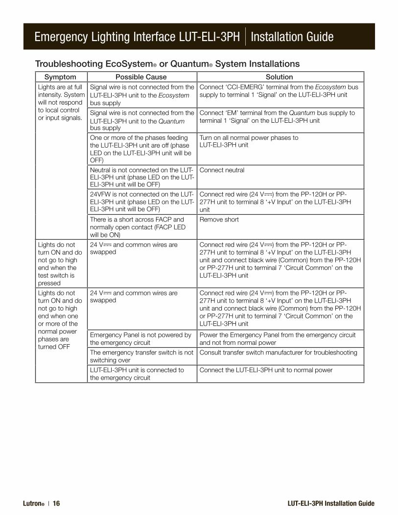
Troubleshooting EcoSystem® or Quantum® System InstallationsSymptom Possible Cause Solution
Lightsareatfullintensity.Systemwillnotrespondtolocalcontrolorinputsignals.
SignalwireisnotconnectedfromtheLUT-ELI-3PHunittotheEcosystembussupply
Connect‘CCI-EMERG’terminalfromtheEcosystembussupplytoterminal1‘Signal’ontheLUT-ELI-3PHunit
SignalwireisnotconnectedfromtheLUT-ELI-3PHunittotheQuantum bussupply
Connect‘EM’terminalfromtheQuantumbussupplytoterminal1‘Signal’ontheLUT-ELI-3PHunit
OneormoreofthephasesfeedingtheLUT-ELI-3PHunitareoff(phaseLEDontheLUT-ELI-3PHunitwillbeOFF)
TurnonallnormalpowerphasestoLUT-ELI-3PHunit
NeutralisnotconnectedontheLUT-ELI-3PHunit(phaseLEDontheLUT-ELI-3PHunitwillbeOFF)
Connectneutral
24VFWisnotconnectedontheLUT-ELI-3PHunit(phaseLEDontheLUT-ELI-3PHunitwillbeOFF)
Connectredwire(24V )fromthePP-120HorPP-277Hunittoterminal8‘+VInput’ontheLUT-ELI-3PHunit
ThereisashortacrossFACPandnormallyopencontact(FACPLEDwillbeON)
Removeshort
LightsdonotturnONanddonotgotohighendwhenthetestswitchispressed
24V andcommonwiresareswapped
Connectredwire(24V )fromthePP-120HorPP-277Hunittoterminal8‘+VInput’ontheLUT-ELI-3PHunitandconnectblackwire(Common)fromthePP-120HorPP-277Hunittoterminal7‘CircuitCommon’ontheLUT-ELI-3PHunit
LightsdonotturnONanddonotgotohighendwhenoneormoreofthenormalpowerphasesareturnedOFF
24V andcommonwiresareswapped
Connectredwire(24V )fromthePP-120HorPP-277Hunittoterminal8‘+VInput’ontheLUT-ELI-3PHunitandconnectblackwire(Common)fromthePP-120HorPP-277Hunittoterminal7‘CircuitCommon’ontheLUT-ELI-3PHunit
EmergencyPanelisnotpoweredbytheemergencycircuit
PowertheEmergencyPanelfromtheemergencycircuitandnotfromnormalpower
Theemergencytransferswitchisnotswitchingover
Consulttransferswitchmanufacturerfortroubleshooting
LUT-ELI-3PHunitisconnectedtotheemergencycircuit
ConnecttheLUT-ELI-3PHunittonormalpower
Emergency Lighting Interface LUT-ELI-3PH | Installation Guide
LUT-ELI-3PH Installation Guide Lutron® | 17
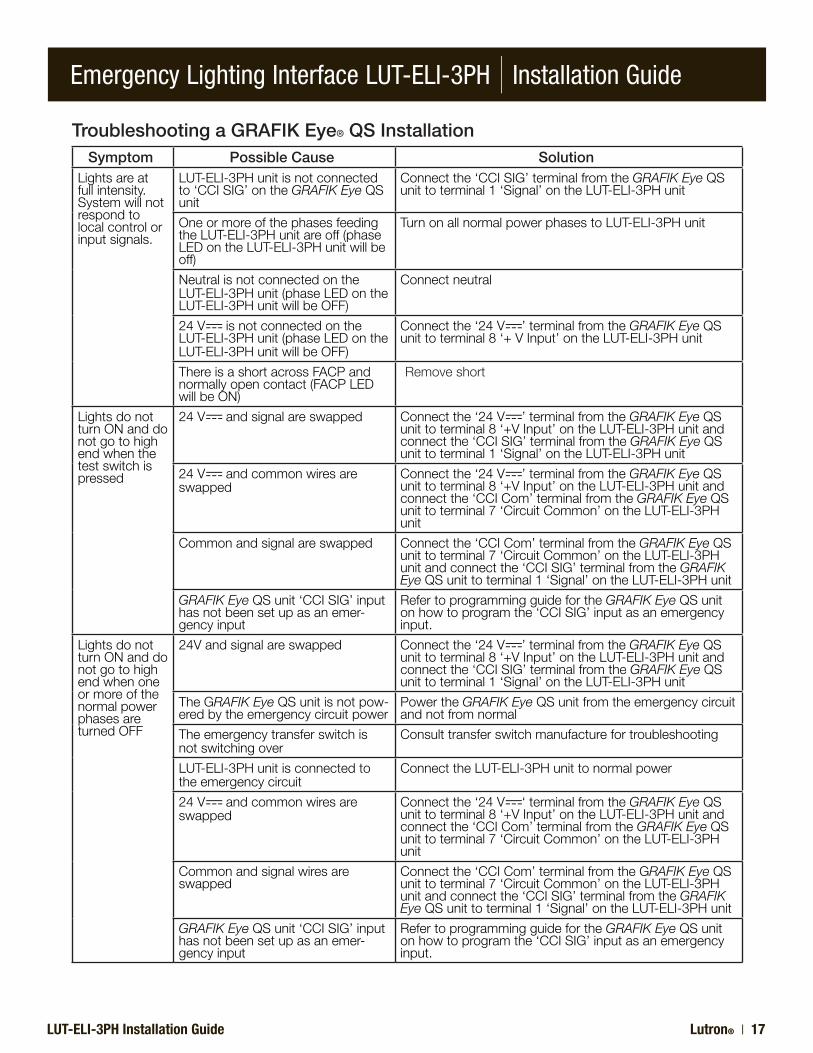
Troubleshooting a GRAFIK Eye® QS InstallationSymptom Possible Cause Solution
Lightsareatfullintensity.Systemwillnotrespondtolocalcontrolorinputsignals.
LUT-ELI-3PHunitisnotconnectedto‘CCISIG’ontheGRAFIK EyeQSunit
Connectthe‘CCISIG’terminalfromtheGRAFIK EyeQSunittoterminal1‘Signal’ontheLUT-ELI-3PHunit
OneormoreofthephasesfeedingtheLUT-ELI-3PHunitareoff(phaseLEDontheLUT-ELI-3PHunitwillbeoff)
TurnonallnormalpowerphasestoLUT-ELI-3PHunit
NeutralisnotconnectedontheLUT-ELI-3PHunit(phaseLEDontheLUT-ELI-3PHunitwillbeOFF)
Connectneutral
24V isnotconnectedontheLUT-ELI-3PHunit(phaseLEDontheLUT-ELI-3PHunitwillbeOFF)
Connectthe‘24V ’terminalfromtheGRAFIK EyeQSunittoterminal8‘+VInput’ontheLUT-ELI-3PHunit
ThereisashortacrossFACPandnormallyopencontact(FACPLEDwillbeON)
Removeshort
LightsdonotturnONanddonotgotohighendwhenthetestswitchispressed
24V andsignalareswapped Connectthe‘24V ’terminalfromtheGRAFIK EyeQSunittoterminal8‘+VInput’ontheLUT-ELI-3PHunitandconnectthe‘CCISIG’terminalfromtheGRAFIK EyeQSunittoterminal1‘Signal’ontheLUT-ELI-3PHunit
24V andcommonwiresareswapped
Connectthe‘24V ’terminalfromtheGRAFIK EyeQSunittoterminal8‘+VInput’ontheLUT-ELI-3PHunitandconnectthe‘CCICom’terminalfromtheGRAFIK EyeQSunittoterminal7‘CircuitCommon’ontheLUT-ELI-3PHunit
Commonandsignalareswapped Connectthe‘CCICom’terminalfromtheGRAFIK EyeQSunittoterminal7‘CircuitCommon’ontheLUT-ELI-3PHunitandconnectthe‘CCISIG’terminalfromtheGRAFIK EyeQSunittoterminal1‘Signal’ontheLUT-ELI-3PHunit
GRAFIK EyeQSunit‘CCISIG’inputhasnotbeensetupasanemer-gencyinput
RefertoprogrammingguidefortheGRAFIK EyeQSunitonhowtoprogramthe‘CCISIG’inputasanemergencyinput.
LightsdonotturnONanddonotgotohighendwhenoneormoreofthenormalpowerphasesareturnedOFF
24Vandsignalareswapped Connectthe‘24V ’terminalfromtheGRAFIK EyeQSunittoterminal8‘+VInput’ontheLUT-ELI-3PHunitandconnectthe‘CCISIG’terminalfromtheGRAFIK EyeQSunittoterminal1‘Signal’ontheLUT-ELI-3PHunit
TheGRAFIK EyeQSunitisnotpow-eredbytheemergencycircuitpower
PowertheGRAFIK EyeQSunitfromtheemergencycircuitandnotfromnormal
Theemergencytransferswitchisnotswitchingover
Consulttransferswitchmanufacturefortroubleshooting
LUT-ELI-3PHunitisconnectedtotheemergencycircuit
ConnecttheLUT-ELI-3PHunittonormalpower
24V andcommonwiresareswapped
Connectthe‘24V ‘terminalfromtheGRAFIK EyeQSunittoterminal8‘+VInput’ontheLUT-ELI-3PHunitandconnectthe‘CCICom’terminalfromtheGRAFIK EyeQSunittoterminal7‘CircuitCommon’ontheLUT-ELI-3PHunit
Commonandsignalwiresareswapped
Connectthe‘CCICom’terminalfromtheGRAFIK EyeQSunittoterminal7‘CircuitCommon’ontheLUT-ELI-3PHunitandconnectthe‘CCISIG’terminalfromtheGRAFIK EyeQSunittoterminal1‘Signal’ontheLUT-ELI-3PHunit
GRAFIK EyeQSunit‘CCISIG’inputhasnotbeensetupasanemer-gencyinput
RefertoprogrammingguidefortheGRAFIK EyeQSunitonhowtoprogramthe‘CCISIG’inputasanemergencyinput.

Emergency Lighting Interface LUT-ELI-3PH | Installation Guide
LUT-ELI-3PH Installation Guide
NOTES:

Emergency Lighting Interface LUT-ELI-3PH | Installation Guide
LUT-ELI-3PH Installation Guide
NOTES:
Emergency Lighting Interface LUT-ELI-3PH | Installation Guide
LUT-ELI-3PH Installation Guide
PrintedintheU.S.A.P/N031-353Rev.A09/10
Internet:www.lutron.com
WORLD HEADQUARTERSLutronElectronicsCo.,Inc.7200SuterRoadCoopersburg,PA18036-1299U.S.A.TOLLFREE:1.800.523.9466(U.S.A.,Canada,andtheCaribbean)Tel:+1.610.282.3800Fax:+1.610.282.1243
EUROPEAN HEADQUARTERSLutronEALtd.LutronHouse6SovereignCloseWappingLondon,E1W3JF,UKFREEPHONE:0800.282.107(U.K.)Tel:+44.(0)20.7702.0657Fax:+44.(0)20.7480.6899
ASIAN HEADQUARTERSSingaporeLutronGL,Ltd.15HoeChiangRoad#07-03TowerFifiteenSingapore089316TOLLFREE:800.120.4491Tel:+65.6220.4666Fax:+65.6220.4333
HONG KONG SALES OFFICETel:+852.2104.7733Fax:+852.2104.7633
LutronElectronicsCo.,Inc.,reservestherighttomakeimprovementsorchangesinitsproductswithoutpriornotice.Althougheveryattemptismadetoensurethatthisinformationisaccurateanduptodate,pleasecheckwithLutrontoconfirmproductavailability,latestspecificationsandsuitabilityforyourapplication.
Lutron Electronics Co., Inc.One Year Limited WarrantyFor a period of one year from the date of purchase, and subject to the exclusions and restrictions described below, Lutron warrants each new unit to be free from manufacturing defects. Lutron will, at its option, either repair the defective unit or issue a credit equal to the purchase price of the defective unit to the Customer against the purchase price of comparable replacement part purchased from Lutron. Replacements for the unit provided by Lutron or, at its sole discretion, an approved vendor may be new, used, repaired, reconditioned, and/or made by a different manufacturer. If the unit is commissioned by Lutron or a Lutron approved third party as part of a Lutron commissioned lighting control system, the term of this warranty will be extended, and any credits against the cost of replacement parts will be prorated, in accordance with the warranty issued with the commissioned system, except that the term of the unit’s warranty term will be measured from the date of its commissioning.EXCLUSIONS AND RESTRICTIONS This Warranty does not cover, and Lutron and its suppliers are not responsible for:1. Damage, malfunction or inoperability diagnosed by Lutron or a Lutron approved third party as caused by normal wear and tear, abuse, misuse, incorrect installation, neglect, accident, interference or environmental factors, such as (a) use of incorrect line voltages, fuses or circuit breakers; (b) failure to install, maintain and operate the unit pursuant to the operating instructions provided by Lutron and the applicable provisions of the National Electrical Code and of the Safety Standards of Underwriter's Laboratories; (c) use of incompatible devices or accessories; (d) improper or insufficient ventilation; (e) unauthorized repairs or adjustments; (f) vandalism; or (g) an act of God, such as fire, lightning, flooding, tornado, earthquake, hurricane or other problems beyond Lutron’s control.2. On-site labor costs to diagnose issues with, and to remove, repair, replace, adjust, reinstall and/or reprogram the unit or any of its components.3. Equipment and parts external to the unit, including those sold or supplied by Lutron (which may be covered by a separate warranty).4. The cost of repairing or replacing other property that is damaged when the unit does not work properly, even if the damage was caused by the unit.EXCEPT AS EXPRESSLY PROVIDED IN THIS WARRANTY, THERE ARE NO EXPRESS OR IMPLIED WARRANTIES OF ANY TYPE, INCLUDING ANY IMPLIED WARRANTIES OF FITNESS FOR A PARTICULAR PURPOSE OR MERCHANTABILITY. LUTRON DOES NOT WARRANT THAT THE UNIT WILL OPERATE WITHOUT INTERRUPTION OR BE ERROR FREE. NO LUTRON AGENT, EMPLOYEE OR REPRESENTATIVE HAS ANY AUTHORITY TO BIND LUTRON TO ANY AFFIRMATION, REPRESENTATION OR WARRANTY CONCERNING THE UNIT. UNLESS AN AFFIRMATION, REPRESENTATION OR WARRANTY MADE BY AN AGENT, EMPLOYEE OR REPRESENTATIVE IS SPECIFICALLY INCLUDED HEREIN, OR IN STANDARD PRINTED MATERIALS PROVIDED BY LUTRON, IT DOES NOT FORM A PART OF THE BASIS OF ANY BARGAIN BETWEEN LUTRON AND CUSTOMER AND WILL NOT IN ANY WAY BE ENFORCEABLE BY CUSTOMER.IN NO EVENT WILL LUTRON OR ANY OTHER PARTY BE LIABLE FOR EXEMPLARY, CONSEQUENTIAL, INCIDENTAL OR SPECIAL DAMAGES (INCLUDING, BUT NOT LIMITED TO, DAMAGES FOR LOSS OF PROFITS, CONFIDENTIAL OR OTHER INFORMATION, OR PRIVACY; BUSINESS INTERRUPTION; PERSONAL INJURY; FAILURE TO MEET ANY DUTY, INCLUDING OF GOOD FAITH OR OF REASONABLE CARE; NEGLIGENCE, OR ANY OTHER PECUNIARY OR OTHER LOSS WHATSOEVER), NOR FOR ANY REPAIR WORK UNDERTAKEN WITHOUT LUTRON’S WRITTEN CONSENT ARISING OUT OF OR IN ANY WAY RELATED TO THE INSTALLATION, DEINSTALLATION, USE OF OR INABILITY TO USE THE UNIT OR OTHERWISE UNDER OR IN CONNECTION WITH ANY PROVISION OF THIS WARRANTY, OR ANY AGREEMENT INCORPORATING THIS WARRANTY, EVEN IN THE EVENT OF THE FAULT, TORT (INCLUDING NEGLIGENCE), STRICT LIABILITY, BREACH OF CONTRACT OR BREACH OF WARRANTY OF LUTRON OR ANY SUPPLIER, AND EVEN IF LUTRON OR ANY OTHER PARTY WAS ADVISED OF THE POSSIBILITY OF SUCH DAMAGES.NOTWITHSTANDING ANY DAMAGES THAT CUSTOMER MIGHT INCUR FOR ANY REASON WHATSOEVER (INCLUDING, WITHOUT LIMITATION, ALL DIRECT DAMAGES AND ALL DAMAGES LISTED ABOVE), THE ENTIRE LIABILITY OF LUTRON AND OF ALL OTHER PARTIES UNDER THIS WARRANTY ON ANY CLAIM FOR DAMAGES ARISING OUT OF OR IN CONNECTION WITH THE MANUFACTURE, SALE, INSTALLATION, DELIVERY, USE, REPAIR, OR REPLACEMENT OF THE UNIT, OR ANY AGREEMENT INCORPORATING THIS WARRANTY, AND CUSTOMER'S SOLE REMEDY FOR THE FOREGOING, WILL BE LIMITED TO THE AMOUNT PAID TO LUTRON BY CUSTOMER FOR THE UNIT. THE FOREGOING LIMITATIONS, EXCLUSIONS AND DISCLAIMERS WILL APPLY TO THE MAXIMUM EXTENT ALLOWED BY APPLICABLE LAW, EVEN IF ANY REMEDY FAILS ITS ESSENTIAL PURPOSE.TO MAKE A WARRANTY CLAIMTo make a warranty claim, promptly notify Lutron within the warranty period described above by calling the Lutron Technical Support Center at (800) 523-9466. Lutron, in its sole discretion, will determine what action, if any, is required under this warranty. To better enable Lutron to address a warranty claim, have the unit's serial and model numbers available when making the call. If Lutron, in its sole discretion, determines that an on-site visit or other remedial action is necessary, Lutron may send a Lutron Services Co. representative or coordinate the dispatch of a representative from a Lutron approved vendor to Customer's site, and/or coordinate a warranty service call between Customer and a Lutron approved vendor.NEC is a registered trademark of National Fire Protection Association, Quincy, Massachusetts. Belden is a registered trademark of Belden, Inc., Richmond, Indiana. Liberty Wire & Cable is a registered trademark of Liberty Wire & Cable, Colorado Springs, Colorado.
Lutron, EcoSystem, GRAFIK Eye, Quantum, RadioTouch, Softswitch128, and the sunburst logo are registered trademarks and Energi Savr Node and LCP128 are trademarks of Lutron Electronics Co., Inc.
© 2010 Lutron Electronics Co, Inc.