emerging issues for coal management in coal mines · management in coal mines bruce robertson...
TRANSCRIPT
Good afternoon Ladies & Gentlemen. Thankyou, Chairman for the introductions. It’s a pleasure to address you today and I trust my talk will maintain the tradition of interesting, practical technical interaction in the Institute My address today covers the current issues and management practices adopted by the coal industry to manage gas in our mines. There have been a great many changes over the last decade in the technology used for gas drainage and there are a a number of significant emerging issues, particularly in relation to carbon pollution taxes which will further change the landscape. But the core value for miners is safety and it is pleasing to note that it has been now over 17 years since the last underground gas–related fatality in this country (at South Bulli), due in part to technology as well as legislation. But we must remain vigilant because it is the skills, experience and discipline of our gas drainage engineers, ventilation officers and statutory officials that ensures that the appropriate gas management controls are in place , and we are facing some challenges in maintaining this capacity.
15/10/2008 Slide 1
AusIMM Technical Meeting Oct 2008
Emerging Issues for Gas Emerging Issues for Gas
Management in Coal MinesManagement in Coal Mines
Bruce RobertsonBruce RobertsonRegional Manager – Underground Technical Services
Anglo Coal Australia Pty LtdAusIMM Technical Meeting, Southern Qld Branch 15/10/08
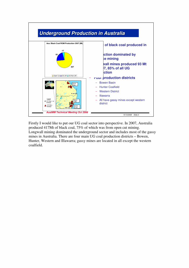
Firstly I would like to put our UG coal sector into perspective. In 2007, Australia produced 417Mt of black coal, 75% of which was from open cut mining. Longwall mining dominated the underground sector and includes most of the gassy mines in Australia. There are four main UG coal production districts – Bowen, Hunter, Western and Illawarra; gassy mines are located in all except the western coalfield.
15/10/2008 Slide 2
AusIMM Technical Meeting Oct 2008
Underground Production in AustraliaUnderground Production in Australia
• 417Mt of black coal produced in 2007
• Production dominated by surface mining
• Longwall mines produced 93 Mt in 2007, 85% of all UG production
• Four production districts
– Bowen Basin
– Hunter Coalfield
– Western District
– Illawarra
– All have gassy mines except western district
Aus. Black Coal ROM Production 2007 (Mt)
307
93
17
Open Cut UG LW UG Non-LW
Legend
LW Mine – no
drainage
LW Mine –
drainage
Bowen
Basin
Hunter
Valley
South
Coast
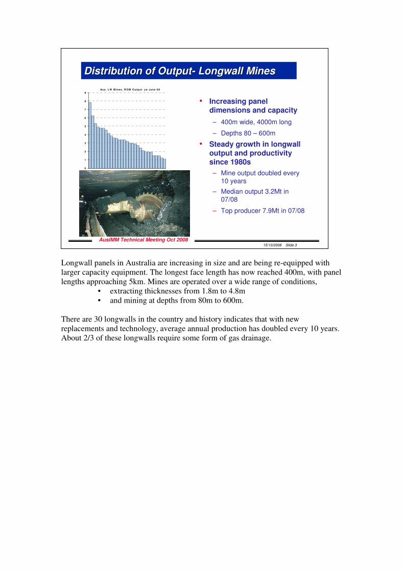
Longwall panels in Australia are increasing in size and are being re-equipped with larger capacity equipment. The longest face length has now reached 400m, with panel lengths approaching 5km. Mines are operated over a wide range of conditions,
• extracting thicknesses from 1.8m to 4.8m • and mining at depths from 80m to 600m.
There are 30 longwalls in the country and history indicates that with new replacements and technology, average annual production has doubled every 10 years. About 2/3 of these longwalls require some form of gas drainage.
15/10/2008 Slide 3
AusIMM Technical Meeting Oct 2008
Distribution of OutputDistribution of Output-- Longwall MinesLongwall Mines
• Increasing panel dimensions and capacity
– 400m wide, 4000m long
– Depths 80 – 600m
• Steady growth in longwall output and productivity since 1980s
– Mine output doubled every 10 years
– Median output 3.2Mt in 07/08
– Top producer 7.9Mt in 07/08
Au s. L W M ines , R O M O utp ut y e J une 0 8
0
1
2
3
4
5
6
7
8
9
7.8
50
6.2
57
5.3
41
4.8
95
4.7
68
4.7
60
4.5
48
4.1
45
3.8
43
3.6
19
3.5
60
3.4
03
3.3
73
3.3
65
3.2
09
3.0
02
2.9
56
2.9
05
2.7
08
2.4
26
2.1
07
1.9
48
1.9
25
1.9
22
1.5
06
1.4
84
1.4
78
1.2
18
1.0
97
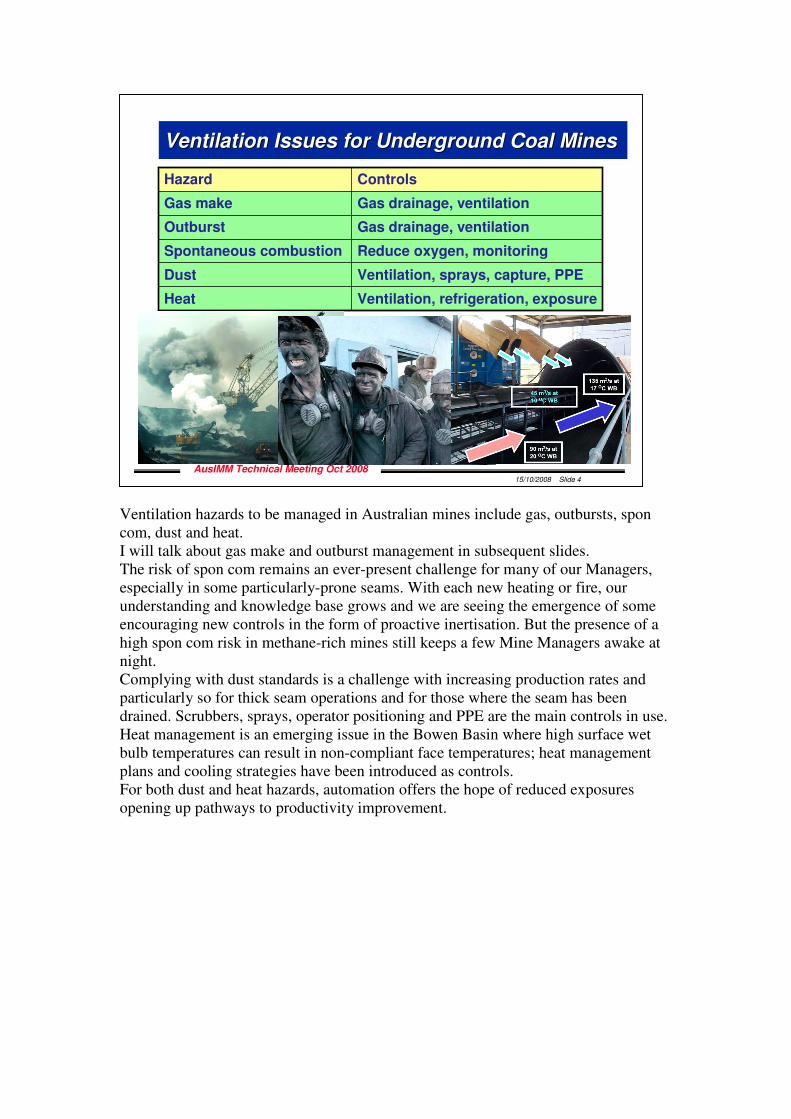
Ventilation hazards to be managed in Australian mines include gas, outbursts, spon com, dust and heat. I will talk about gas make and outburst management in subsequent slides. The risk of spon com remains an ever-present challenge for many of our Managers, especially in some particularly-prone seams. With each new heating or fire, our understanding and knowledge base grows and we are seeing the emergence of some encouraging new controls in the form of proactive inertisation. But the presence of a high spon com risk in methane-rich mines still keeps a few Mine Managers awake at night. Complying with dust standards is a challenge with increasing production rates and particularly so for thick seam operations and for those where the seam has been drained. Scrubbers, sprays, operator positioning and PPE are the main controls in use. Heat management is an emerging issue in the Bowen Basin where high surface wet bulb temperatures can result in non-compliant face temperatures; heat management plans and cooling strategies have been introduced as controls. For both dust and heat hazards, automation offers the hope of reduced exposures opening up pathways to productivity improvement.
15/10/2008 Slide 4
AusIMM Technical Meeting Oct 2008
Ventilation Issues for Underground Coal MinesVentilation Issues for Underground Coal Mines
Ventilation, refrigeration, exposureHeat
Ventilation, sprays, capture, PPEDust
Reduce oxygen, monitoringSpontaneous combustion
Gas drainage, ventilationOutburst
Gas drainage, ventilationGas make
ControlsHazard
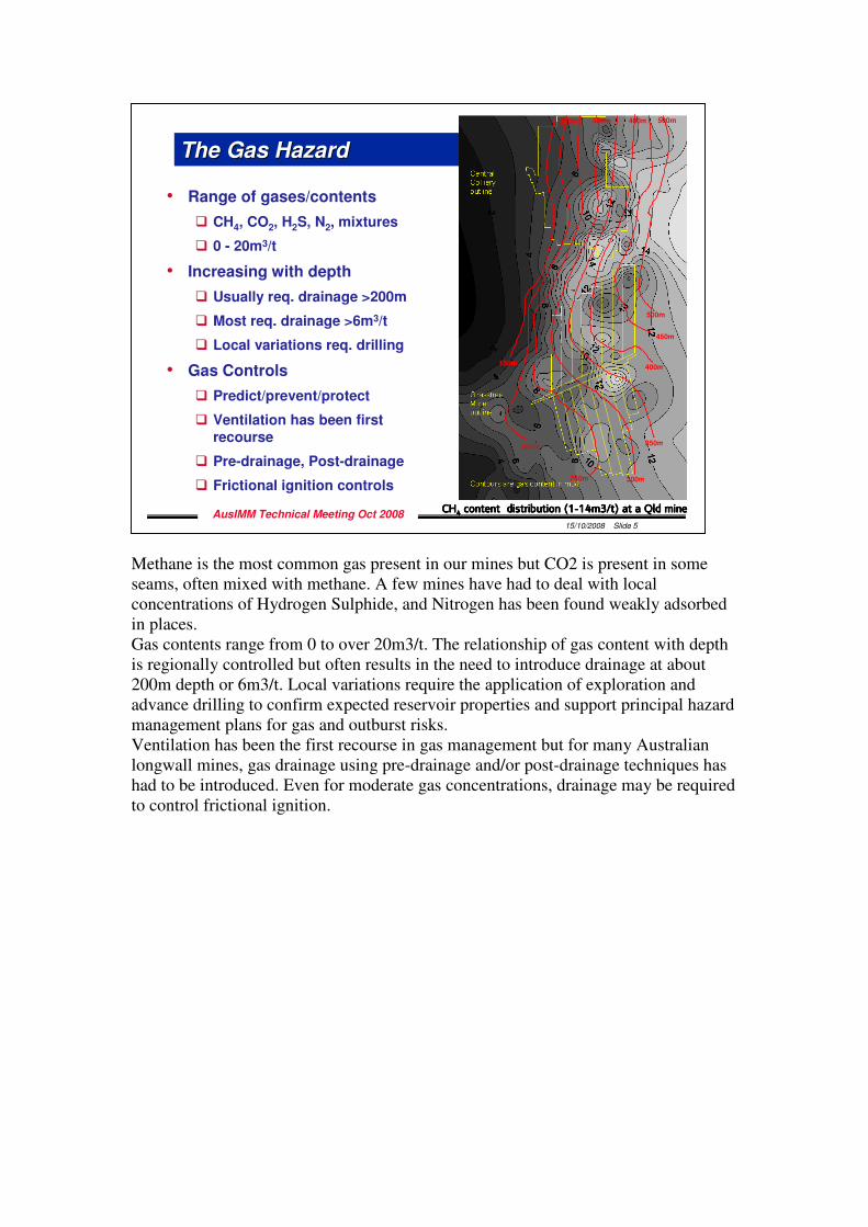
Methane is the most common gas present in our mines but CO2 is present in some seams, often mixed with methane. A few mines have had to deal with local concentrations of Hydrogen Sulphide, and Nitrogen has been found weakly adsorbed in places. Gas contents range from 0 to over 20m3/t. The relationship of gas content with depth is regionally controlled but often results in the need to introduce drainage at about 200m depth or 6m3/t. Local variations require the application of exploration and advance drilling to confirm expected reservoir properties and support principal hazard management plans for gas and outburst risks. Ventilation has been the first recourse in gas management but for many Australian longwall mines, gas drainage using pre-drainage and/or post-drainage techniques has had to be introduced. Even for moderate gas concentrations, drainage may be required to control frictional ignition.
15/10/2008 Slide 5
AusIMM Technical Meeting Oct 2008
The Gas HazardThe Gas Hazard
• Range of gases/contents
� CH4, CO2, H2S, N2, mixtures
� 0 - 20m3/t
• Increasing with depth
� Usually req. drainage >200m
� Most req. drainage >6m3/t
� Local variations req. drilling
• Gas Controls
� Predict/prevent/protect
� Ventilation has been first recourse
� Pre-drainage, Post-drainage
� Frictional ignition controls
CHCHCHCH4444content distribution (1content distribution (1content distribution (1content distribution (1----14m3/t) at a Qld mine14m3/t) at a Qld mine14m3/t) at a Qld mine14m3/t) at a Qld mine
500m
400m
300m
200m
250m
350m
450m
150m
500m400m300m200m
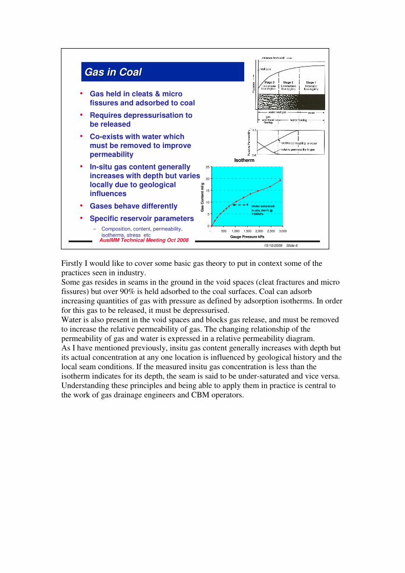
Firstly I would like to cover some basic gas theory to put in context some of the practices seen in industry. Some gas resides in seams in the ground in the void spaces (cleat fractures and micro fissures) but over 90% is held adsorbed to the coal surfaces. Coal can adsorb increasing quantities of gas with pressure as defined by adsorption isotherms. In order for this gas to be released, it must be depressurised. Water is also present in the void spaces and blocks gas release, and must be removed to increase the relative permeability of gas. The changing relationship of the permeability of gas and water is expressed in a relative permeability diagram. As I have mentioned previously, insitu gas content generally increases with depth but its actual concentration at any one location is influenced by geological history and the local seam conditions. If the measured insitu gas concentration is less than the isotherm indicates for its depth, the seam is said to be under-saturated and vice versa. Understanding these principles and being able to apply them in practice is central to the work of gas drainage engineers and CBM operators.
15/10/2008 Slide 6
AusIMM Technical Meeting Oct 2008
Gas in CoalGas in Coal
• Gas held in cleats & micro
fissures and adsorbed to coal
• Requires depressurisation to be released
• Co-exists with water which must be removed to improve permeability
• In-situ gas content generally increases with depth but varies locally due to geological influences
• Gases behave differently
• Specific reservoir parameters
– Composition, content, permeability, isotherms, stress etc
Isotherm
0
5
10
15
20
25
- 500 1,000 1,500 2,000 2,500 3,000
Gauge Pressure kPa
Gas C
on
ten
t m
l/g
Under-saturated:
In-situ 9m3/t @ 1500kPa
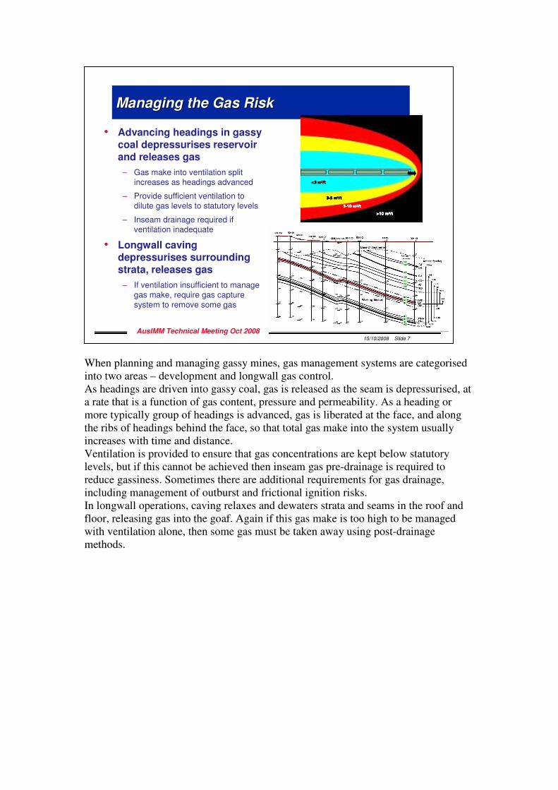
When planning and managing gassy mines, gas management systems are categorised into two areas – development and longwall gas control. As headings are driven into gassy coal, gas is released as the seam is depressurised, at a rate that is a function of gas content, pressure and permeability. As a heading or more typically group of headings is advanced, gas is liberated at the face, and along the ribs of headings behind the face, so that total gas make into the system usually increases with time and distance. Ventilation is provided to ensure that gas concentrations are kept below statutory levels, but if this cannot be achieved then inseam gas pre-drainage is required to reduce gassiness. Sometimes there are additional requirements for gas drainage, including management of outburst and frictional ignition risks. In longwall operations, caving relaxes and dewaters strata and seams in the roof and floor, releasing gas into the goaf. Again if this gas make is too high to be managed with ventilation alone, then some gas must be taken away using post-drainage methods.
15/10/2008 Slide 7
AusIMM Technical Meeting Oct 2008
Managing the Gas RiskManaging the Gas Risk
• Advancing headings in gassy coal depressurises reservoir and releases gas
– Gas make into ventilation split increases as headings advanced
– Provide sufficient ventilation to dilute gas levels to statutory levels
– Inseam drainage required if ventilation inadequate
• Longwall caving depressurises surrounding strata, releases gas
– If ventilation insufficient to manage gas make, require gas capture system to remove some gas
<3 m<3 m<3 m<3 m3333/t/t/t/t
3333----5 m5 m5 m5 m3333/t/t/t/t
5555----10 m10 m10 m10 m3333/t/t/t/t
>10 m>10 m>10 m>10 m3333/t/t/t/t
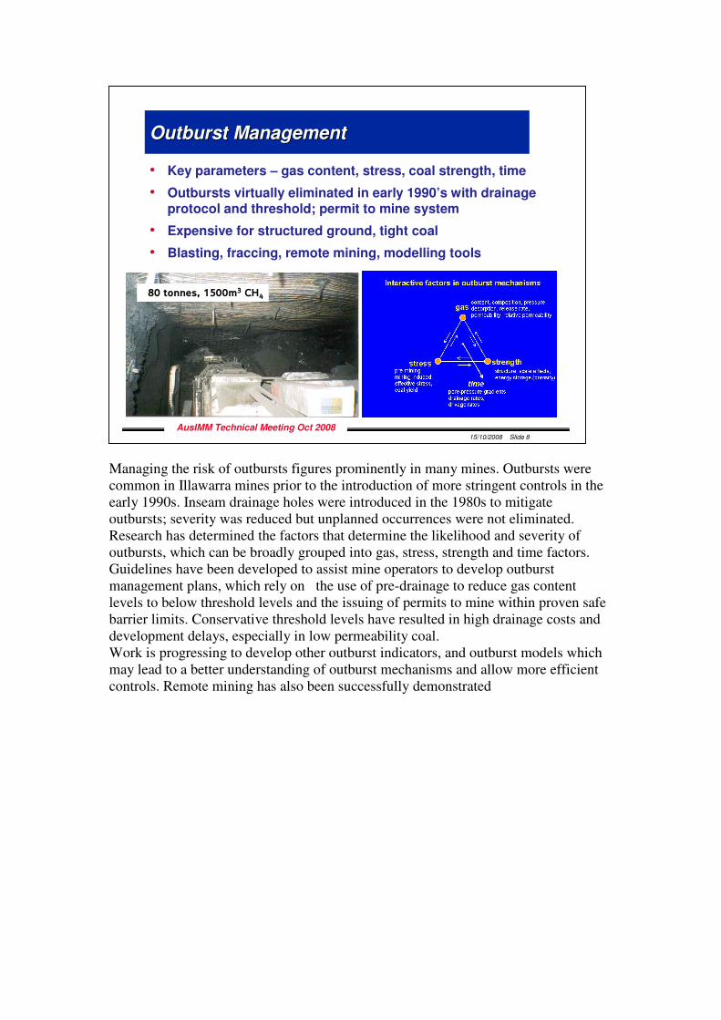
Managing the risk of outbursts figures prominently in many mines. Outbursts were common in Illawarra mines prior to the introduction of more stringent controls in the early 1990s. Inseam drainage holes were introduced in the 1980s to mitigate outbursts; severity was reduced but unplanned occurrences were not eliminated. Research has determined the factors that determine the likelihood and severity of outbursts, which can be broadly grouped into gas, stress, strength and time factors. Guidelines have been developed to assist mine operators to develop outburst management plans, which rely on the use of pre-drainage to reduce gas content levels to below threshold levels and the issuing of permits to mine within proven safe barrier limits. Conservative threshold levels have resulted in high drainage costs and development delays, especially in low permeability coal. Work is progressing to develop other outburst indicators, and outburst models which may lead to a better understanding of outburst mechanisms and allow more efficient controls. Remote mining has also been successfully demonstrated
15/10/2008 Slide 8
AusIMM Technical Meeting Oct 2008
Outburst ManagementOutburst Management
• Key parameters – gas content, stress, coal strength, time
• Outbursts virtually eliminated in early 1990’s with drainage protocol and threshold; permit to mine system
• Expensive for structured ground, tight coal
• Blasting, fraccing, remote mining, modelling tools
80 tonnes, 1500m3 CH4
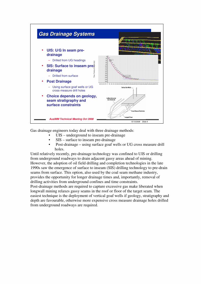
Gas drainage engineers today deal with three drainage methods:
• UIS – underground to inseam pre-drainage • SIS – surface to inseam pre-drainage • Post-drainage – using surface goaf wells or UG cross measure drill
holes. Until relatively recently, pre-drainage technology was confined to UIS or drilling from underground roadways to drain adjacent gassy areas ahead of mining. However, the adoption of oil field drilling and completion technologies in the late 1990s saw the emergence of surface to inseam (SIS) drilling technology to pre-drain seams from surface. This option, also used by the coal seam methane industry, provides the opportunity for longer drainage times and, importantly, removal of drilling activities from underground confines and time constraints. Post-drainage methods are required to capture excessive gas make liberated when longwall mining relaxes gassy seams in the roof or floor of the target seam. The easiest technique is the deployment of vertical goaf wells if geology, stratigraphy and depth are favourable, otherwise more expensive cross measure drainage holes drilled from underground roadways are required.
15/10/2008 Slide 9
AusIMM Technical Meeting Oct 2008
Gas Drainage SystemsGas Drainage Systems
• UIS: U/G In seam pre-drainage
– Drilled from UG headings
• SIS: Surface to inseam pre-drainage
– Drilled from surface
• Post Drainage
– Using surface goaf wells or UG cross-measure drill holes
• Choice depends on geology, seam stratigraphy and surface constraints
Survey: Working survey (MG 106 H2 b/First MNC Lucas MRD)
Vertical Section at 170.54° [m]
Tru
e V
ert
ical
Dep
th [
m]
-80 -60 -40 -20 0 20 40 60 80 100120140160180200220240260280300320340360380400420440460480500520
0
20
40
60
80
100
120
140
160
180
200
220
240
260
8"
4 1/2" slots5 1/2"
0
20
40
60
80
100
120
140
160
180
200
220
240260
280300
320340 360 380 400 420
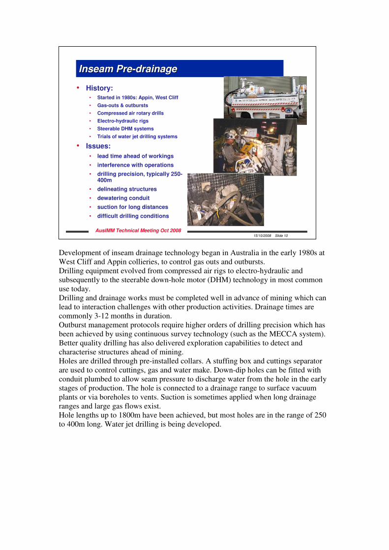
Development of inseam drainage technology began in Australia in the early 1980s at West Cliff and Appin collieries, to control gas outs and outbursts. Drilling equipment evolved from compressed air rigs to electro-hydraulic and subsequently to the steerable down-hole motor (DHM) technology in most common use today. Drilling and drainage works must be completed well in advance of mining which can lead to interaction challenges with other production activities. Drainage times are commonly 3-12 months in duration. Outburst management protocols require higher orders of drilling precision which has been achieved by using continuous survey technology (such as the MECCA system). Better quality drilling has also delivered exploration capabilities to detect and characterise structures ahead of mining. Holes are drilled through pre-installed collars. A stuffing box and cuttings separator are used to control cuttings, gas and water make. Down-dip holes can be fitted with conduit plumbed to allow seam pressure to discharge water from the hole in the early stages of production. The hole is connected to a drainage range to surface vacuum plants or via boreholes to vents. Suction is sometimes applied when long drainage ranges and large gas flows exist. Hole lengths up to 1800m have been achieved, but most holes are in the range of 250 to 400m long. Water jet drilling is being developed.
15/10/2008 Slide 10
AusIMM Technical Meeting Oct 2008
Inseam PreInseam Pre--drainagedrainage
• History:
• Started in 1980s: Appin, West Cliff
• Gas-outs & outbursts
• Compressed air rotary drills
• Electro-hydraulic rigs
• Steerable DHM systems
• Trials of water jet drilling systems
• Issues:
• lead time ahead of workings
• interference with operations
• drilling precision, typically 250-400m
• delineating structures
• dewatering conduit
• suction for long distances
• difficult drilling conditions
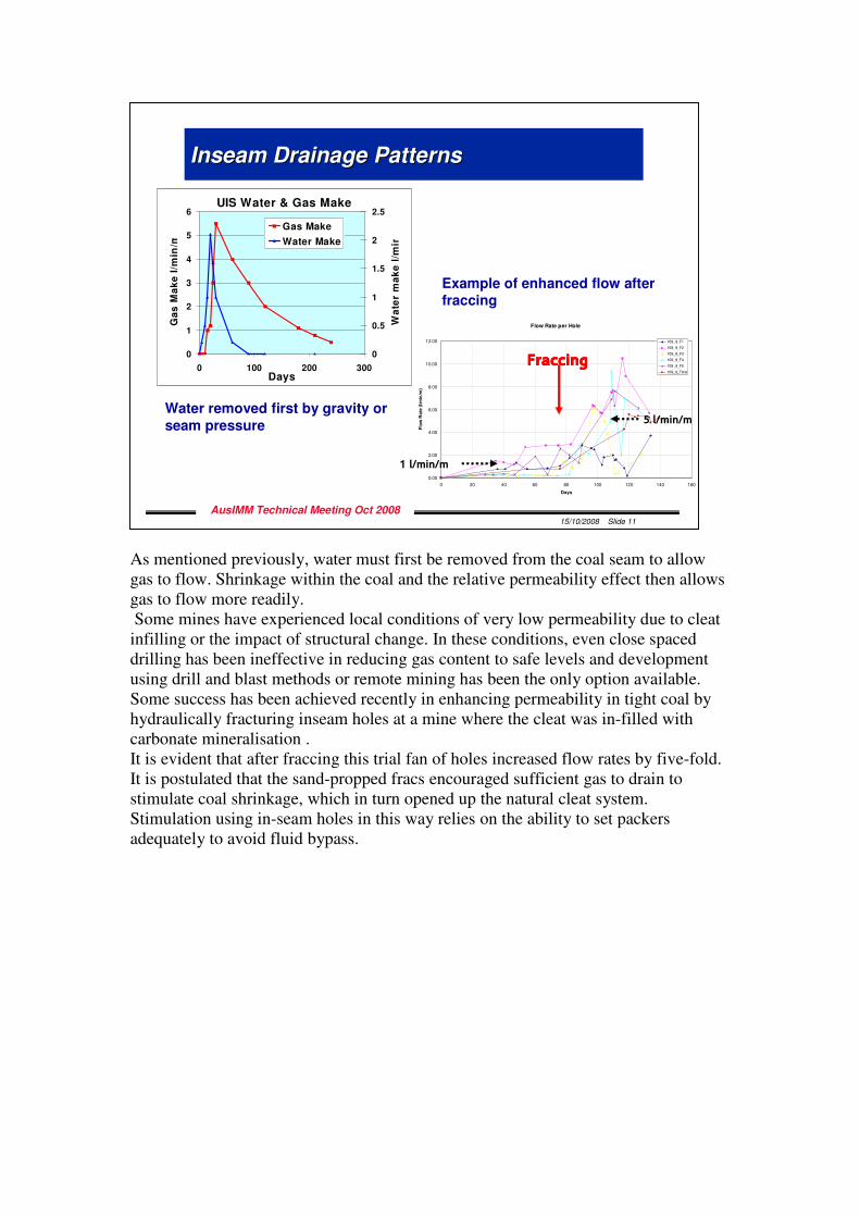
As mentioned previously, water must first be removed from the coal seam to allow gas to flow. Shrinkage within the coal and the relative permeability effect then allows gas to flow more readily. Some mines have experienced local conditions of very low permeability due to cleat infilling or the impact of structural change. In these conditions, even close spaced drilling has been ineffective in reducing gas content to safe levels and development using drill and blast methods or remote mining has been the only option available. Some success has been achieved recently in enhancing permeability in tight coal by hydraulically fracturing inseam holes at a mine where the cleat was in-filled with carbonate mineralisation . It is evident that after fraccing this trial fan of holes increased flow rates by five-fold. It is postulated that the sand-propped fracs encouraged sufficient gas to drain to stimulate coal shrinkage, which in turn opened up the natural cleat system. Stimulation using in-seam holes in this way relies on the ability to set packers adequately to avoid fluid bypass.
15/10/2008 Slide 11
AusIMM Technical Meeting Oct 2008
Inseam Drainage PatternsInseam Drainage Patterns
Flow Rate per Hole
0.00
2.00
4.00
6.00
8.00
10.00
12.00
0 20 40 60 80 100 120 140 160
Days
Flo
w R
ate
(l/m
in/m
)
109_9_F1
109_9_F2
109_9_F3
109_9_F4
109_9_F5
109_9_Total
FraccingFraccingFraccingFraccing
1 l/min/m
5 l/min/m
UIS Water & Gas Make
0
1
2
3
4
5
6
0 100 200 300Days
Ga
s M
ak
e l
/min
/m
0
0.5
1
1.5
2
2.5
Wa
ter
ma
ke
l/m
in
Gas Make
Water Make
Water removed first by gravity or
seam pressure
Example of enhanced flow after fraccing
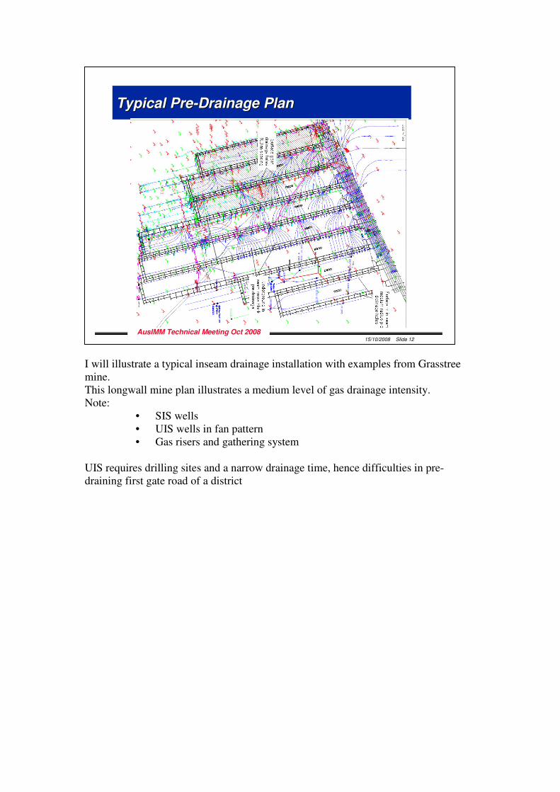
I will illustrate a typical inseam drainage installation with examples from Grasstree mine. This longwall mine plan illustrates a medium level of gas drainage intensity. Note:
• SIS wells • UIS wells in fan pattern • Gas risers and gathering system
UIS requires drilling sites and a narrow drainage time, hence difficulties in pre-draining first gate road of a district
15/10/2008 Slide 12
AusIMM Technical Meeting Oct 2008
Typical PreTypical Pre--Drainage PlanDrainage Plan
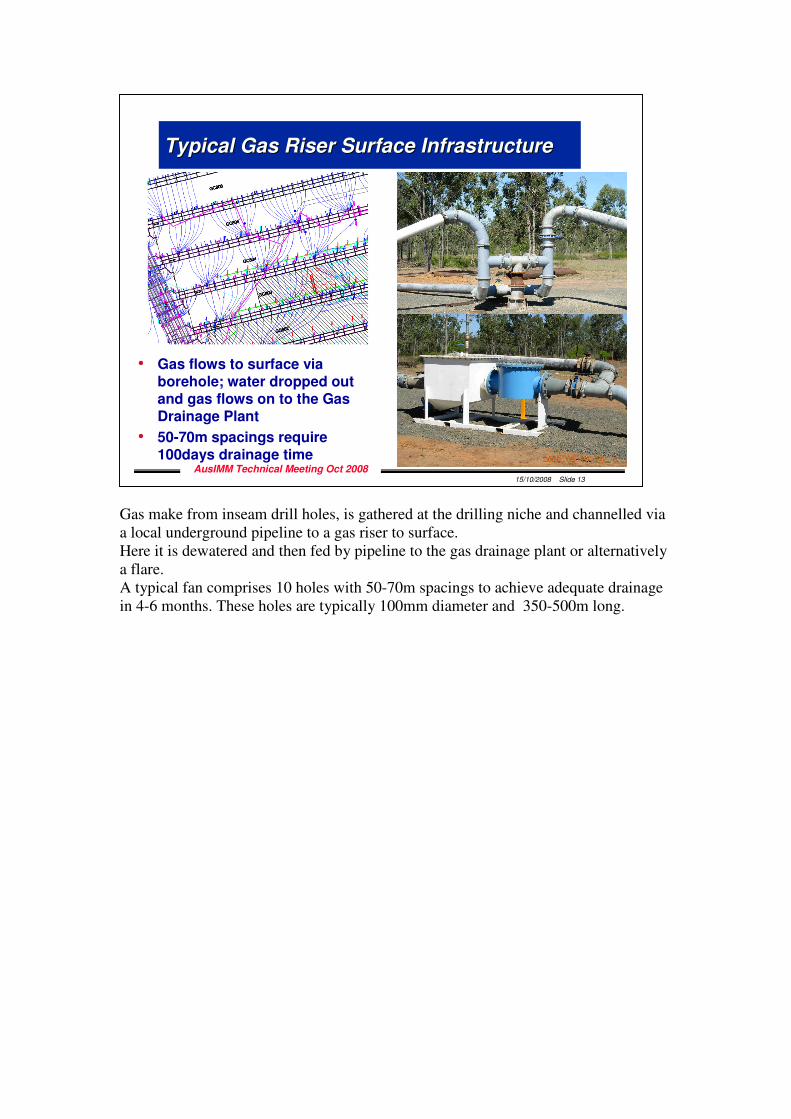
Gas make from inseam drill holes, is gathered at the drilling niche and channelled via a local underground pipeline to a gas riser to surface. Here it is dewatered and then fed by pipeline to the gas drainage plant or alternatively a flare. A typical fan comprises 10 holes with 50-70m spacings to achieve adequate drainage in 4-6 months. These holes are typically 100mm diameter and 350-500m long.
15/10/2008 Slide 13
AusIMM Technical Meeting Oct 2008
Typical Gas Riser Surface InfrastructureTypical Gas Riser Surface Infrastructure
• Gas flows to surface via borehole; water dropped out and gas flows on to the Gas Drainage Plant
• 50-70m spacings require 100days drainage time
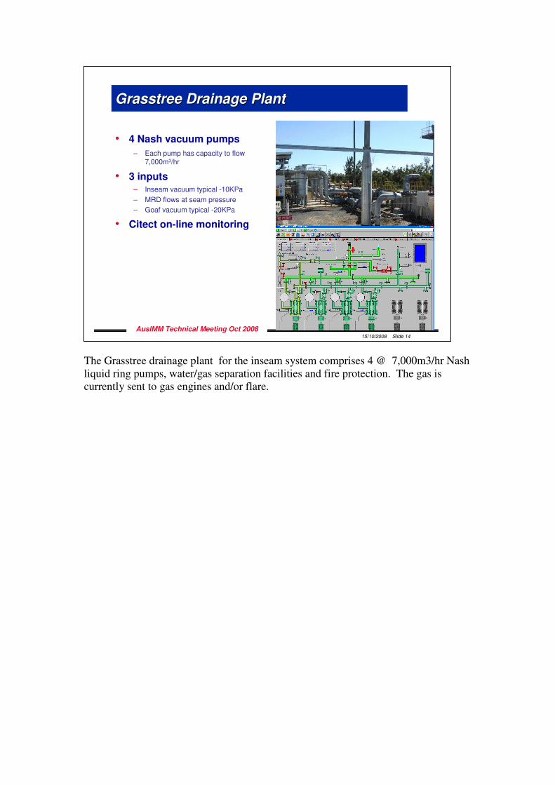
The Grasstree drainage plant for the inseam system comprises 4 @ 7,000m3/hr Nash liquid ring pumps, water/gas separation facilities and fire protection. The gas is currently sent to gas engines and/or flare.
15/10/2008 Slide 14
AusIMM Technical Meeting Oct 2008
Grasstree Drainage PlantGrasstree Drainage Plant
• 4 Nash vacuum pumps
– Each pump has capacity to flow 7,000m3/hr
• 3 inputs – Inseam vacuum typical -10KPa
– MRD flows at seam pressure
– Goaf vacuum typical -20KPa
• Citect on-line monitoring
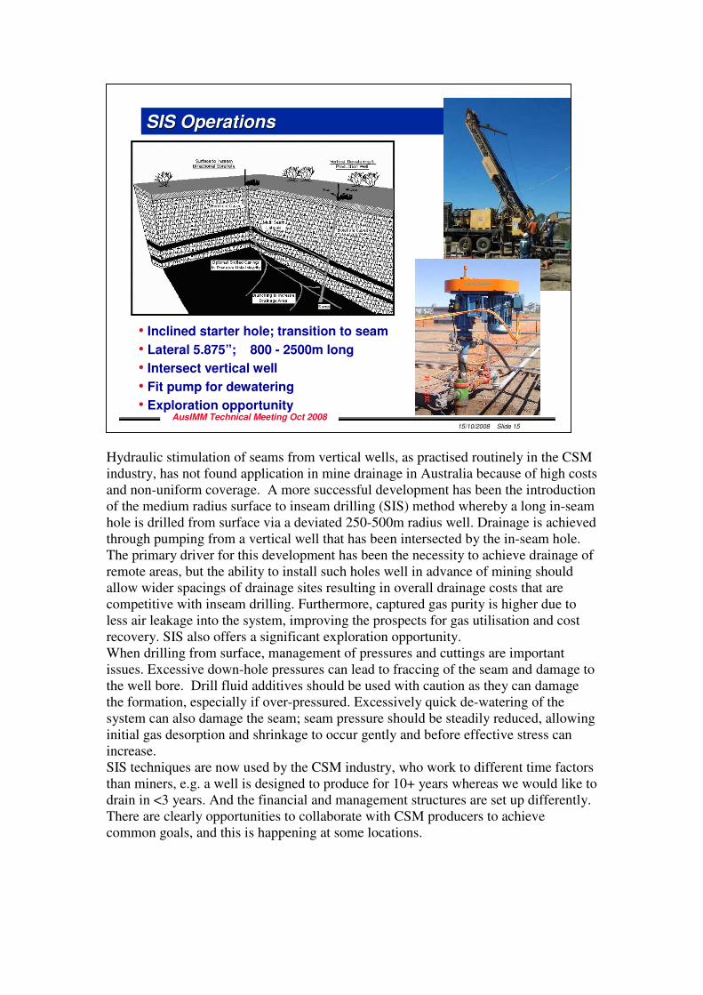
Hydraulic stimulation of seams from vertical wells, as practised routinely in the CSM industry, has not found application in mine drainage in Australia because of high costs and non-uniform coverage. A more successful development has been the introduction of the medium radius surface to inseam drilling (SIS) method whereby a long in-seam hole is drilled from surface via a deviated 250-500m radius well. Drainage is achieved through pumping from a vertical well that has been intersected by the in-seam hole. The primary driver for this development has been the necessity to achieve drainage of remote areas, but the ability to install such holes well in advance of mining should allow wider spacings of drainage sites resulting in overall drainage costs that are competitive with inseam drilling. Furthermore, captured gas purity is higher due to less air leakage into the system, improving the prospects for gas utilisation and cost recovery. SIS also offers a significant exploration opportunity. When drilling from surface, management of pressures and cuttings are important issues. Excessive down-hole pressures can lead to fraccing of the seam and damage to the well bore. Drill fluid additives should be used with caution as they can damage the formation, especially if over-pressured. Excessively quick de-watering of the system can also damage the seam; seam pressure should be steadily reduced, allowing initial gas desorption and shrinkage to occur gently and before effective stress can increase. SIS techniques are now used by the CSM industry, who work to different time factors than miners, e.g. a well is designed to produce for 10+ years whereas we would like to drain in <3 years. And the financial and management structures are set up differently. There are clearly opportunities to collaborate with CSM producers to achieve common goals, and this is happening at some locations.
15/10/2008 Slide 15
AusIMM Technical Meeting Oct 2008
SIS OperationsSIS Operations
• Inclined starter hole; transition to seam
• Lateral 5.875”; 800 - 2500m long
• Intersect vertical well
• Fit pump for dewatering
• Exploration opportunity
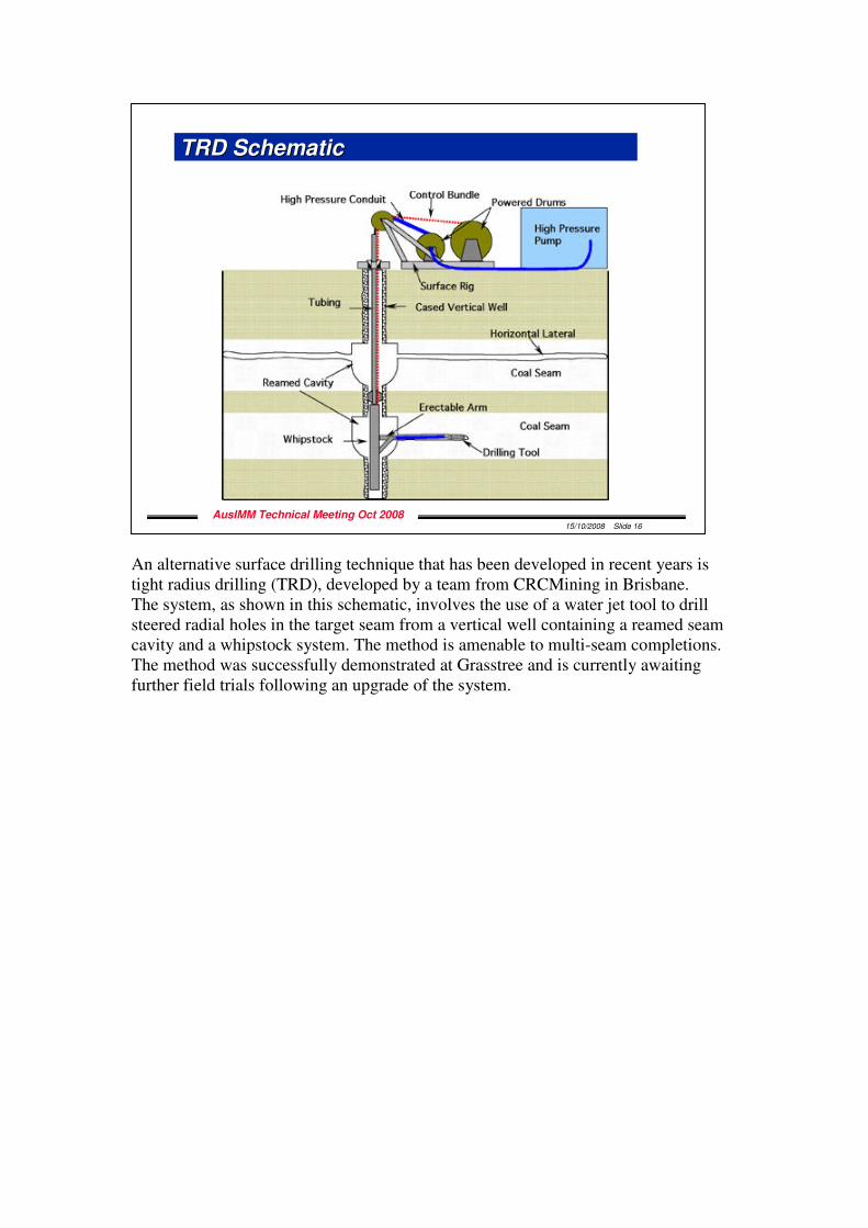
An alternative surface drilling technique that has been developed in recent years is tight radius drilling (TRD), developed by a team from CRCMining in Brisbane. The system, as shown in this schematic, involves the use of a water jet tool to drill steered radial holes in the target seam from a vertical well containing a reamed seam cavity and a whipstock system. The method is amenable to multi-seam completions. The method was successfully demonstrated at Grasstree and is currently awaiting further field trials following an upgrade of the system.
15/10/2008 Slide 16
AusIMM Technical Meeting Oct 2008
TRD SchematicTRD Schematic
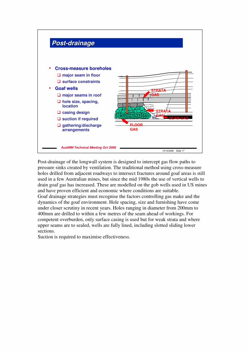
Post-drainage of the longwall system is designed to intercept gas flow paths to pressure sinks created by ventilation. The traditional method using cross-measure holes drilled from adjacent roadways to intersect fractures around goaf areas is still used in a few Australian mines, but since the mid 1980s the use of vertical wells to drain goaf gas has increased. These are modelled on the gob wells used in US mines and have proven efficient and economic where conditions are suitable. Goaf drainage strategies must recognise the factors controlling gas make and the dynamics of the goaf environment. Hole spacing, size and furnishing have come under closer scrutiny in recent years. Holes ranging in diameter from 200mm to 400mm are drilled to within a few metres of the seam ahead of workings. For competent overburden, only surface casing is used but for weak strata and where upper seams are to sealed, wells are fully lined, including slotted sliding lower sections. Suction is required to maximise effectiveness.
15/10/2008 Slide 17
AusIMM Technical Meeting Oct 2008
PostPost--drainagedrainage
• Cross-measure boreholes
� major seam in floor
� surface constraints
• Goaf wells
� major seams in roof
� hole size, spacing, location
� casing design
� suction if required
� gathering/discharge arrangements
SEAM GAS
STRATA
GAS
STRATA
GAS
FLOOR
GAS
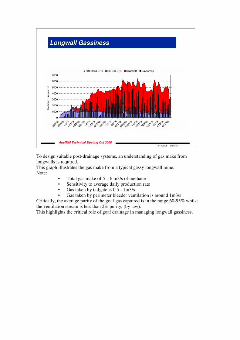
To design suitable post-drainage systems, an understanding of gas make from longwalls is required. This graph illustrates the gas make from a typical gassy longwall mine. Note:
• Total gas make of 5 – 6 m3/s of methane • Sensitivity to average daily production rate • Gas taken by tailgate is 0.5 - 1m3/s • Gas taken by perimeter bleeder ventilation is around 1m3/s
Critically, the average purity of the goaf gas captured is in the range 60-95% whilst the ventilation stream is less than 2% purity, (by law). This highlights the critical role of goaf drainage in managing longwall gassiness.
15/10/2008 Slide 18
AusIMM Technical Meeting Oct 2008
Longwall GassinessLongwall Gassiness
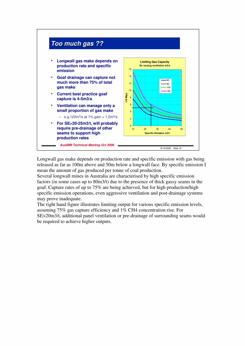
Longwall gas make depends on production rate and specific emission with gas being released as far as 100m above and 50m below a longwall face. By specific emission I mean the amount of gas produced per tonne of coal production. Several longwall mines in Australia are characterised by high specific emission factors (in some cases up to 80m3/t) due to the presence of thick gassy seams in the goaf. Capture rates of up to 75% are being achieved, but for high production/high specific emission operations, even aggressive ventilation and post-drainage systems may prove inadequate. The right hand figure illustrates limiting output for various specific emission levels, assuming 75% gas capture efficiency and 1% CH4 concentration rise. For SE>20m3/t, additional panel ventilation or pre-drainage of surrounding seams would be required to achieve higher outputs.
15/10/2008 Slide 19
AusIMM Technical Meeting Oct 2008
Too much gas ??Too much gas ??
• Longwall gas make depends on
production rate and specific emission
• Goaf drainage can capture not much more than 75% of total gas make
• Current best practice goaf capture is 4-5m3/s
• Ventilation can manage only a
small proportion of gas make
– e.g.120m3/s at 1% gain = 1.2m3/s
• For SE>20-25m3/t, will probably require pre-drainage of other
seams to support high production rates
Limiting Gas Capacity
for varying ventilation m3/s
0
2
4
6
8
10
12
14
16
10 20 30 40 50
Specific Emission m3/t
LW
Mtp
a
60
80
100
120
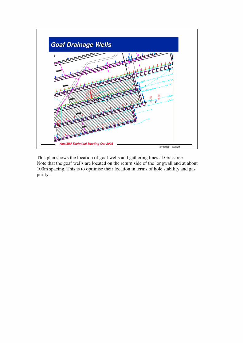
This plan shows the location of goaf wells and gathering lines at Grasstree. Note that the goaf wells are located on the return side of the longwall and at about 100m spacing. This is to optimise their location in terms of hole stability and gas purity.
15/10/2008 Slide 20
AusIMM Technical Meeting Oct 2008
Goaf Drainage WellsGoaf Drainage Wells
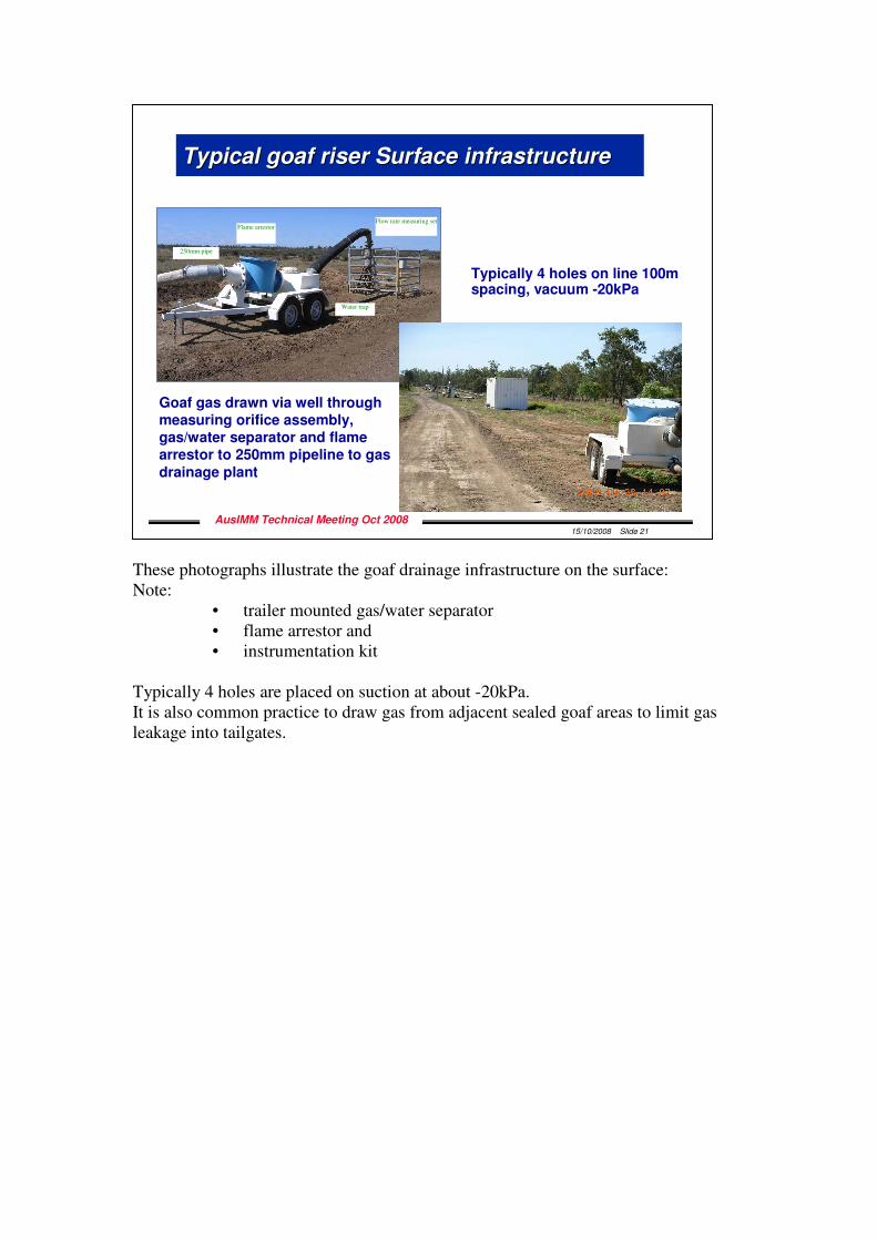
These photographs illustrate the goaf drainage infrastructure on the surface: Note:
• trailer mounted gas/water separator • flame arrestor and • instrumentation kit
Typically 4 holes are placed on suction at about -20kPa. It is also common practice to draw gas from adjacent sealed goaf areas to limit gas leakage into tailgates.
15/10/2008 Slide 21
AusIMM Technical Meeting Oct 2008
Typical goaf riser Surface infrastructureTypical goaf riser Surface infrastructure
Flow rate measuring setFlame arrestor
Water trap
250mm pipe
Typically 4 holes on line 100m spacing, vacuum -20kPa
Goaf gas drawn via well through measuring orifice assembly, gas/water separator and flame arrestor to 250mm pipeline to gas
drainage plant
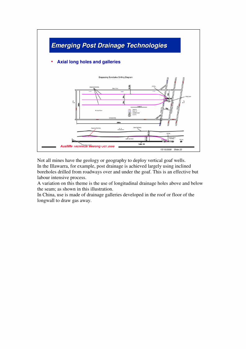
Not all mines have the geology or geography to deploy vertical goaf wells. In the Illawarra, for example, post drainage is achieved largely using inclined boreholes drilled from roadways over and under the goaf. This is an effective but labour intensive process. A variation on this theme is the use of longitudinal drainage holes above and below the seam; as shown in this illustration. In China, use is made of drainage galleries developed in the roof or floor of the longwall to draw gas away.
15/10/2008 Slide 22
AusIMM Technical Meeting Oct 2008
Emerging Post Drainage TechnologiesEmerging Post Drainage Technologies
• Axial long holes and galleries
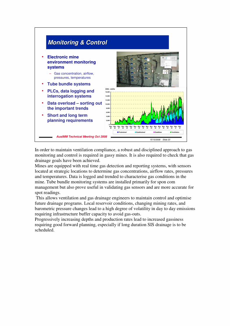
In order to maintain ventilation compliance, a robust and disciplined approach to gas monitoring and control is required in gassy mines. It is also required to check that gas drainage goals have been achieved. Mines are equipped with real time gas detection and reporting systems, with sensors located at strategic locations to determine gas concentrations, airflow rates, pressures and temperatures. Data is logged and trended to characterise gas conditions in the mine. Tube bundle monitoring systems are installed primarily for spon com management but also prove useful in validating gas sensors and are more accurate for spot readings. This allows ventilation and gas drainage engineers to maintain control and optimise future drainage programs. Local reservoir conditions, changing mining rates, and barometric pressure changes lead to a high degree of volatility in day to day emissions requiring infrastructure buffer capacity to avoid gas-outs. Progressively increasing depths and production rates lead to increased gassiness requiring good forward planning, especially if long duration SIS drainage is to be scheduled.
15/10/2008 Slide 23
AusIMM Technical Meeting Oct 2008
Monitoring & ControlMonitoring & Control
• Electronic mine environment monitoring systems
– Gas concentration, airflow, pressures, temperatures
• Tube bundle systems
• PLCs, data logging and interrogation systems
• Data overload – sorting out
the important trends
• Short and long term planning requirements
Central Colliery Gassiness
0
2,000
4,000
6,000
8,000
10,000
12,000
14,000
16,000
May-
85
May-
86
May-
87
May-
88
May-
89
May-
90
May-
91
May-
92
May-
93
May-
94
May-
95
May-
96
May-
97
May-
98
May-
99
May-
00
May-
01
May-
02
CH4 - m3/hr
Predrained Goafdrained Goafblow Ventilation
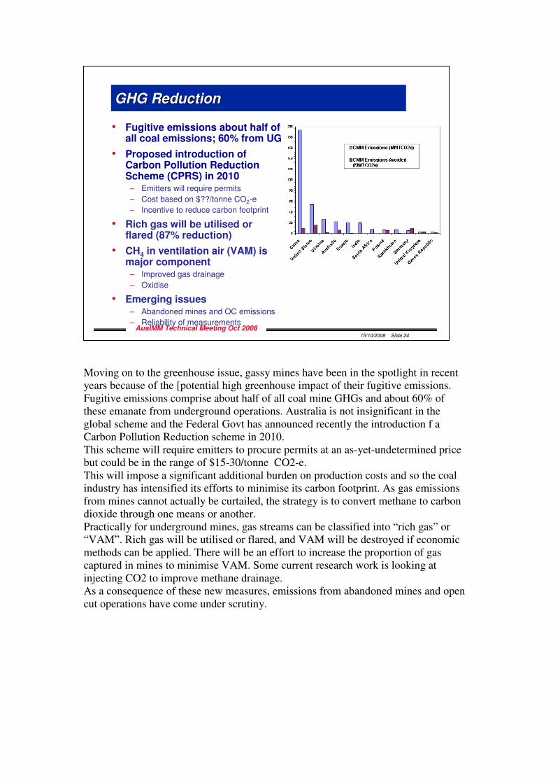
Moving on to the greenhouse issue, gassy mines have been in the spotlight in recent years because of the [potential high greenhouse impact of their fugitive emissions. Fugitive emissions comprise about half of all coal mine GHGs and about 60% of these emanate from underground operations. Australia is not insignificant in the global scheme and the Federal Govt has announced recently the introduction f a Carbon Pollution Reduction scheme in 2010. This scheme will require emitters to procure permits at an as-yet-undetermined price but could be in the range of $15-30/tonne CO2-e. This will impose a significant additional burden on production costs and so the coal industry has intensified its efforts to minimise its carbon footprint. As gas emissions from mines cannot actually be curtailed, the strategy is to convert methane to carbon dioxide through one means or another. Practically for underground mines, gas streams can be classified into “rich gas” or “VAM”. Rich gas will be utilised or flared, and VAM will be destroyed if economic methods can be applied. There will be an effort to increase the proportion of gas captured in mines to minimise VAM. Some current research work is looking at injecting CO2 to improve methane drainage. As a consequence of these new measures, emissions from abandoned mines and open cut operations have come under scrutiny.
15/10/2008 Slide 24
AusIMM Technical Meeting Oct 2008
GHG ReductionGHG Reduction
• Fugitive emissions about half of all coal emissions; 60% from UG
• Proposed introduction of Carbon Pollution Reduction Scheme (CPRS) in 2010
– Emitters will require permits
– Cost based on $??/tonne CO2-e
– Incentive to reduce carbon footprint
• Rich gas will be utilised or flared (87% reduction)
• CH4 in ventilation air (VAM) is major component
– Improved gas drainage
– Oxidise
• Emerging issues– Abandoned mines and OC emissions
– Reliability of measurements
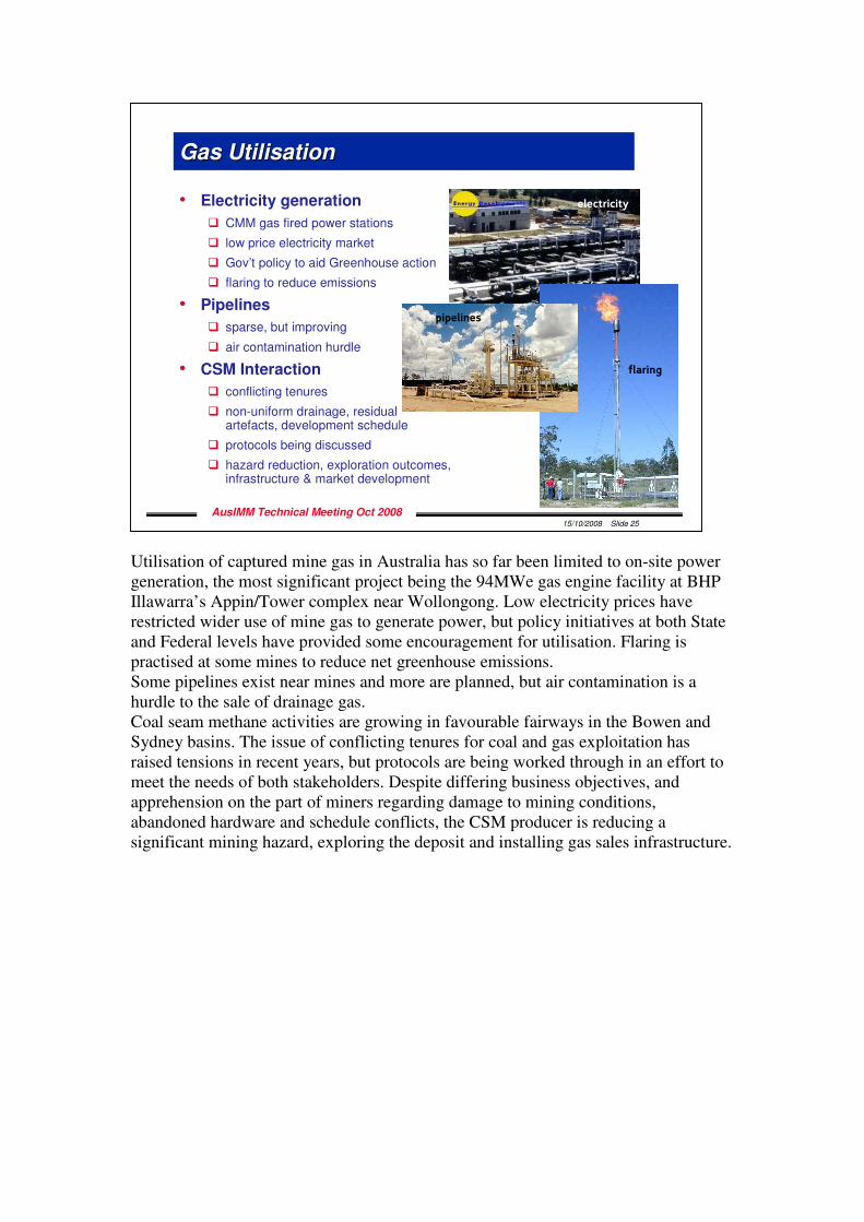
Utilisation of captured mine gas in Australia has so far been limited to on-site power generation, the most significant project being the 94MWe gas engine facility at BHP Illawarra’s Appin/Tower complex near Wollongong. Low electricity prices have restricted wider use of mine gas to generate power, but policy initiatives at both State and Federal levels have provided some encouragement for utilisation. Flaring is practised at some mines to reduce net greenhouse emissions. Some pipelines exist near mines and more are planned, but air contamination is a hurdle to the sale of drainage gas. Coal seam methane activities are growing in favourable fairways in the Bowen and Sydney basins. The issue of conflicting tenures for coal and gas exploitation has raised tensions in recent years, but protocols are being worked through in an effort to meet the needs of both stakeholders. Despite differing business objectives, and apprehension on the part of miners regarding damage to mining conditions, abandoned hardware and schedule conflicts, the CSM producer is reducing a significant mining hazard, exploring the deposit and installing gas sales infrastructure.
15/10/2008 Slide 25
AusIMM Technical Meeting Oct 2008
Gas Gas UtilisationUtilisation
• Electricity generation
� CMM gas fired power stations
� low price electricity market
� Gov’t policy to aid Greenhouse action
� flaring to reduce emissions
• Pipelines
� sparse, but improving
� air contamination hurdle
• CSM Interaction
� conflicting tenures
� non-uniform drainage, residual artefacts, development schedule
� protocols being discussed
� hazard reduction, exploration outcomes, infrastructure & market development
electricity
flaring
pipelines
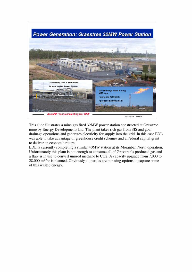
This slide illustrates a mine gas fired 32MW power station constructed at Grasstree mine by Energy Developments Ltd. The plant takes rich gas from SIS and goaf drainage operations and generates electricity for supply into the grid. In this case EDL was able to take advantage of greenhouse credit schemes and a Federal capital grant to deliver an economic return. EDL is currently completing a similar 40MW station at its Moranbah North operation. Unfortunately this plant is not enough to consume all of Grasstree’s produced gas and a flare is in use to convert unused methane to CO2. A capacity upgrade from 7,000 to 28,000 m3/hr is planned. Obviously all parties are pursuing options to capture some of this wasted energy.
15/10/2008 Slide 26
AusIMM Technical Meeting Oct 2008
Power Generation: Grasstree 32MW Power StationPower Generation: Grasstree 32MW Power Station
Gas mixing tank & Scrubbers
At front end of Power Station
Gas Drainage Plant Flaring
MRD gas
� currently 7200m2/hr
� proposed 28,000 m3/hr
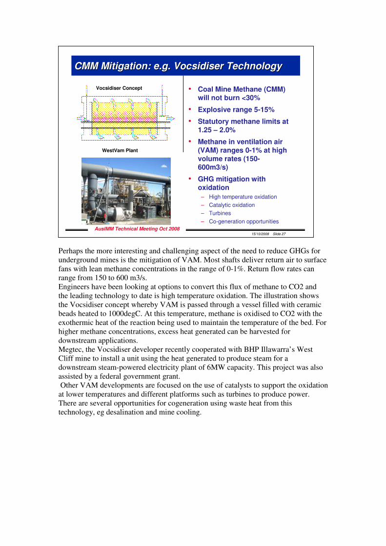
Perhaps the more interesting and challenging aspect of the need to reduce GHGs for underground mines is the mitigation of VAM. Most shafts deliver return air to surface fans with lean methane concentrations in the range of 0-1%. Return flow rates can range from 150 to 600 m3/s. Engineers have been looking at options to convert this flux of methane to CO2 and the leading technology to date is high temperature oxidation. The illustration shows the Vocsidiser concept whereby VAM is passed through a vessel filled with ceramic beads heated to 1000degC. At this temperature, methane is oxidised to CO2 with the exothermic heat of the reaction being used to maintain the temperature of the bed. For higher methane concentrations, excess heat generated can be harvested for downstream applications. Megtec, the Vocsidiser developer recently cooperated with BHP Illawarra’s West Cliff mine to install a unit using the heat generated to produce steam for a downstream steam-powered electricity plant of 6MW capacity. This project was also assisted by a federal government grant. Other VAM developments are focused on the use of catalysts to support the oxidation at lower temperatures and different platforms such as turbines to produce power. There are several opportunities for cogeneration using waste heat from this technology, eg desalination and mine cooling.
15/10/2008 Slide 27
AusIMM Technical Meeting Oct 2008
CMM Mitigation: e.g. Vocsidiser TechnologyCMM Mitigation: e.g. Vocsidiser Technology
• Coal Mine Methane (CMM) will not burn <30%
• Explosive range 5-15%
• Statutory methane limits at 1.25 – 2.0%
• Methane in ventilation air (VAM) ranges 0-1% at high volume rates (150-600m3/s)
• GHG mitigation with oxidation
– High temperature oxidation
– Catalytic oxidation
– Turbines
– Co-generation opportunities
Vocsidiser Concept
WestVam Plant
In conclusion, I would see the outlook for methane management in mines as a combination of challenge and opportunity. I have noted that mines will generally become more gassy with increasing depth and production intensity; this will put pressure on ventilation capability at mines and require higher standards of competency and professionalism in our ventilation and gas drainage engineers, as has existed in other mining communities such as deep metalliferous mines and there will be increasing demands on statutory officials as well. The financial implications of the emerging carbon pollution reduction scheme will intensify this need providing opportunities for significant cost avoidance in GHG permits. Pre-drainage of non-worked seams will become more common to reduce longwall gassiness and to capture more rich gas. The ability to provide adequate, reliable ventilation will require more efficient ventilation systems; one means of delivering and controlling this is the use of automation to control ventilation control devices and goaf drainage operations. And there will be a need to work more closely with our CSM resource partners to not only ensure that we don’t encumber each other but rather capitalise on the different financial systems related to our businesses. Thankyou for your attention.
15/10/2008 Slide 28
AusIMM Technical Meeting Oct 2008
OutlookOutlook
• More intensive, gassier mining environments and GHG costs will drive higher degrees of competency and professionalism in ventilation and gas drainage engineers
• Pre-drainage of non-worked seams will become more common to reduce longwall gassiness and capture more CMM
• The requirement for more efficient ventilation systems will stimulate automation of VCDs and goaf drainage controls
• Improved coordination of CSM and miners