eminent air (thailand) co., ltd. magnetic full falling film
TRANSCRIPT

Commercial Air Conditioners 2017
Magnetic Full Falling FilmCentrifugal Chiller
Cooling Capacity: 150~700RT50/60Hz
Eminent Air (Thailand) Co., Ltd.405 Moo 5 Soi Soonthonvasu,
Bhudharaksa Road, Preakasamai,Muang, Samutprakarn ,10280 Thailand
Tel. +662 083-5555 Fax: +662 033-6234 or 35
E-mail: [email protected]: www.eminent.co.th
ISO 14001 2004
OHSA
S18001 OHSAS
18001

Unit Member
Full falling f ilm evaporator(patented)
Economizer Control panel
Starter panel
Condenserwith integral sub-cooler
FeaturesEnergy Saving
6% higher efficiency than single-stage compression.
Lower speed and higher reliability.
Two-stage compressor
Condenser
Economizer
Evaporator
Impellers
Two-stage compressing
Motor efficiency exceeds 95%, with the highest efficiency up to 97%.
High power density and compact size.
The motor is cooled by refrigerant, high efficiency and long life span.
High-speed permanent magnet motor
Adopting magnetic bearing and without the need for lubrication. The refrigerating system can realize 100% oil free
operation to eliminate the heat transfer loss resulting from lubricating oil.
Heat transfer optimization through oil-free design
00 1 2 3 4 5 6 7 8
(% Oil)
(% Energy loss)
2
4
6
8
10
12
14
16
3.5% oil content=8% capacity reduced
AHRI data indicates that when the lubricating oil amount of centrifugal chiller evaporator reaches 3.5%, COP will reduce by over 8%.
Year-by-year operation comparison between Magnetic and common model.
(Operating life: Y)
(% Capacity)
30%
0 1 2 3 4 5 76 8 9 10
50%
90%
70%
110%
The e�ciency of chiller containing oil will
reduce with increase of its running time.
Magnetic
Common model
Feat
ures
Magnetic compressorwith integral VFD

Feat
ures
Feat
ures
2A
400A
The high power factor eliminates the need for a power factor connection capacitor.
0.95 power factor
The rotor is levitating in the non-contact magnetic bearing when the unit is started. As the starting torque is small, a smooth
starting process becomes possible in combination with the optimum control of soft start and VFD. The starting current of a
single compressor is only 2A and no impact on the grid.
Compare a 700RT magnetic centrifugal chiller to a typical centrifugal chiller. During one year, a system can help customers get
an annual saving rate of 45%. For the whole operating life, the operating cost saving is considerable and it is worth to invest a
magnetic centrifugal chiller system.
Zero in-rush current Energy cost comparison
Input values
Based on IPLV
AHRI
700
4000
0.0813
Standard
Capacity (RT)
Operating Hrs
kW/h Rate ($)
Model ACL(AHRI) IPLV Operating Cost ($)
406 11.23 41338
745266.229406
CWCM-700
CWCH-700
Star-delta start
Magnetic start
1.0
0.9
0.8
0.7
0.6
0.5
0.4
0.3
0.2
0.1
0.0
20
Chiller load(%)
Pow
er fa
ctor
10090807060504030
Chiller with inverter drive
Constant speed chiller without power factor correction capacitor
0
20000
40000
60000
80000
CWCM-700 CWCH-700
APPROXIMATE ANNUAL COST
reduced45%

Feat
ures
Feat
ures
3-Phase Mains 380-480VAC
50/60Hz
Line Reactor Recti�erDC Link
Capacitors IGBT Motor
DC Bus+
+300V
-300V
DC Bus-
-300V
+300VIGBT
ControlSCR
Control
Softstart Controller
Motor/Bearing Controller
High-Voltage DC-DC Converter
Magnetic compressor
Technology leading
Pressure and temperature sensor
Motor and bearing control
Two-stage centrifugal compression
Inlet guide vane
Soft starter
Permanent magnetic synchronous motor
Integral VFD
High e�ciency direct-drive technology
No acceleration gear and transmission loss, higher efficiency.
Simpler transmission system, less moving parts, higher reliability.
Magnetic technology is combined to significantly reduce the running noise.
Digital control
The magnetic compressor uses the integral variable frequency drive and soft starter.
VFD+IGV regulation, chiller capacity range can be 10-100%.
Lower in-rush current.
Intelligent control to avoid surge and choke points.
First created the application of full falling film evaporator and adopted spray technology to achieve film evaporation on the
surface of heat exchange tube, greatly increase the overall heat transfer efficiency and reduce refrigerant charge by up to 40%.
The patented refrigerant distributor can improve the homogeneity of liquid, avoid drying, fully display the performance
of heat exchange tube and increase the unit efficiency.
Full Falling-�lm Evaporating Technology
40% reduction of refrigerant charge
Flooded type Mixed falling �lm
Patent No: 201210414053.9; 201220552298.
Full falling �lm achieved 40% less refrigerant charge
than �ooded type
Full falling f ilm achieved 25% less refrigerant charge than the mixed �ooded type
Full falling f ilm
Almost zero percent liquid level
Magnetic compressor is a miniaturized, highly innovative compressor with magnetic bearing, VFD and permanent magnetic
synchronous motor technologies.
Realized oil-free, effective and safe operation.
Flash refrigerant vapor
From condenser
EXV
To evaporator
Fixed ori�ce
Advanced throttling technology
Adopting the throttle method of Fixed orifice+EXV:
Precisely liquid level control, best performance of condenser and evaporator.
Fast response, avoid hot gas bypass, higher efficiency in part load.
Energy saving and reliable.

Feat
ures
Feat
ures
Less moving parts
Less maintenance
Power outage protection
Each compressor has four 8,000μF capacitors for energy storage and to filter DC voltage fluctuations. In case of a power
failure, the capacitors provide continuity power to the bearings to keep the shaft levitated, allowing the motor to turn into
a generator and to power itself down to a stop. Extended life testing confirms the system’s remarkable durability.
Intelligent surge controlReal-time monitoring of compressor running status, adjust compressor speed and inlet guide vane opening through the
powerful control system to ensure safe and high efficiency of compressor.
Magnetic bearing guarantees total levitating of the rotor during operation. No contact between the bearing and rotor, no
fricition and structural vibtation.
The motor directly drives the rotor, the compressor has one moving component and system without oil supply system
and oil recovery system, greatly reduced unit parts, less fault points and higher reliability.
Two-stage compression of impeller
Position sensor Position sensor Thrust bearing
Rotor
Solenoid coil
Front bearing Rear bearingDC motor
No gear drive No mechanical bearing No lubricating system
Environmental friendlyQuieter operation
No physical contact between moving metal parts, very low sound and vibration levels are achieved.
With reference to AHRI standard 575, sound pressure ratings as low as 78dB(A). That makes it ideal for
sound sensitive environments such as schools, performance halls, museums, condominiums and libraries.
LEED
Zero-ozone depletion R134a refrigerant, friendly and doesn’ t have an elimination cycle.
Full falling-film technology reduces refrigerant charge by up to 40%, which will enable you
to qualify for maximum Leadership in Energy and Environmental Design (LEED) points for
Enhanced Refrigerant Management. And with chiller’ s high efficiency, you could also earn
additional points for the Optimize Energy Performance (EAc1) credit.
Less maintenanceNo oil system, no need for regular maintenance. 95% maintanance procedures reduced.
Modular design of compressor, all parts are universal, plug and play, easy to maintain.
Comparison between various centrifugal chillers maintenance items.
No. R123 chiller R134a chiller
1 Once a year Once every three years
2 Once a year Once a year
3 4 times a year 4 times a year
4 Once a week Once a week
5 Once a month Once a month
6 Once a year Once a year
7 Once every three years Once every three years
8 Once every three years Once every three years
9 Once a year Once a year
10 Once a year Once a year
11 Once a week No
12
Maintenance items
Motor winding check
Oil heater check
Oil pump insulation check
Compressor vibration test
Oil filter pressure drop detect
Oil quality check
Oil pump pressure detect
Oil filter change
Oil change
Contactor and overload setting check
Refrigerant clearness check
Refrigerant filter change 4 times a year No
Magnetic centrifugal chiller(oil-free)
No
No
No
No
No
No
No
No
No
No
No
No
50
87
150150
140
160
20
40
60
80
100
120
0IndoorNoise dB(A) Magnetic Typical centrifugal chiller Airplane takeof f
78

Spec
i�ca
tions
Dim
ensi
ons
Length A Width B Height CModel
Dimensions Location dimension of connecting pipe Maintenance space
mm
3500
3500
3500
1180
1180
1180
2075
2075
2075
335
335
335
635
635
635
1045
1045
1045
1395
1395
1395
368
368
368
/
/
/
3500
3500
3500
1200
1200
1200
1200
1200
1200
DN200
DN200
DN200
DN200
DN200
DN200
1500
1500
1500
mm mm mm mm mm mm mm mm mm mm mm mm
D E F G H M I J K L
CCWD-250
CCWD-300
CCWD-350
Diameter of Diameter ofconnecting
pipe for evaporator
connecting pipe for
condenser
mm
2500
2500
1180
1180
2075
2075
355
355
615
615
1030
1030
1410
1410
368
368
/
/
2500
2500
1200
1200
1200
1200
DN150
DN150
DN150
DN150
1500
1500
mm mm mm mm mm mm mm mm mm mm mm mm
Dimensions Location dimension of connecting pipe Maintenance space Diameter of Diameter of
Length A Width BModel Height C D E F G H M I J K L
CCWD-150
CCWD-200
connecting pipe for
evaporator
connecting pipe for
condenser
150 200 250 300 350 400 450 500 550 600 650 700
150 190 250 300 350 400 450 500 550 600 650 700
527.4 668.0 879.0 1055 1231 1406 1582 1758 1934 2110 2286 2461
45 57 76 91 106 121 136 151 166 181 197 212
Power input kW 90.79 111.7 145.3 178.8 198.3 226.7 255.4 282.2 304.5 340.6 367.8 391.6
COP kW/kW 5.809 5.978 6.051 5.900 6.205 6.205 6.194 6.230 6.351 6.193 6.213 6.285
Conf igured power kW 120 240 240 240 240 360 360 360 480 480 480 480
Chilled water f low
Cooling water f low
82 103 136 163 191 218 245 272 299 327 354 381
Chilled water inlet/outlet temp kPa 72.8 75.9 44.9 47.2 48.1 73.2 74.1 75.3 47.8 48.5 49.8 51.6
2 2 2 2 2 2 2 2 2 2 2 2
Chilled water inlet/outlet temp °C
Fouling factor
DN150 DN150 DN200 DN200 DN200 DN200 DN200 DN200 DN250 DN250 DN250 DN250
m3/h
m3/h
102 136 170 204 238 273 307 341 375 409 443 477
Cooling water pressure drop kPa 31.7 4.1 48.2 49.6 50.9 77.3 81.3 82.6 55.9 55.9 57 58
2 2 2 2 2 2 2 2 2 2 2 2
Cooling water inlet/outlet temp °C
Fouling factor m2.°C/kW
m2.°C/kW
DN150 DN150 DN200 DN200 DN200 DN200 DN200 DN200 DN250 DN250 DN250 DN250
Shipping weight kg 2565 2685 3235 3375 3515 4160 4300 4440 6730 6870 6990 7110
Running weight kg 2685 2805 3355 3495 3635 4280 4420 4560 6850 6990 7110 7230
Unit length mm 2500 2500 3500 3500 3500 4000 4000 4000 4100 4100 4100 4100
Unit width mm 1180 1180 1180 1180 1180 1380 1380 1380 2500 2500 2500 2500
Unit height mm 2075 2075 2075 2075 2075 2155 2155 2155 2150 2150 2150 2150
Packing length mm 2500 2500 3500 3500 3500 4000 4000 4000 4100 4100 4100 4100
Packing width mm 1650 1650 1650 1650 1650 1850 1850 1850 2500 2500 2500 2500
Packing height mm 2225 2225 2225 2225 2225 2305 2305 2305 2300 2300 2300 2300
Evaporator
Compressor
Efficiency
Model(CCWD-***)
Dimension
Weight
Condenser
Cooling capacity
Connection type
Pass
Connection type
Pass
Power supply
Starting method
Motor cooled by
RT
29.44/34.67
0.044
Victaulic
Water pipe connection
kW
104 kcal/h
380V-3Ph-50/60Hz
VFD
Refrigerant
12.22/6.67
0.0176
Victaulic
Water pipe connection
DimensionsSpeci�cations
Pipe drawing space I
Chilled water outlet
Space L on the top of the unit
Chilled water inlet
Cooling water outlet
Cooling water inlet
Operation and maintenancespace at the left side
Operation and maintenance space at the right side
C
G
FED
JHB
KA
Single-compressor unit
Two-compressors unit
Pipe drawing space I
Space L on the top of the unit
Chilled water outlet
Chilled water inlet
Cooling water outlet
Cooling water inlet
Operation andmaintenance
space at the left side
AK
BH
D
J
EF
F2
v
G
C
Operation andmaintenance space
at the right side
Note:
Performance and efficiency are based on AHRI 550/590-2011.
The design max. working pressure for both evaporator and condenser are 1.0MPa, higher pressure demand can be customized.

Dim
ensi
ons
Dim
ensi
ons
Model
Dimensions
P
mm
2970
2970
2970
2970
Q
mm
860
860
860
860
R
mm
200
200
200
200
S
mm
50
50
50
50
T
mm
2680
2680
2680
2680
W
mm
3670
3670
3670
3670
V
mm
350
350
350
350
U
mm
860
860
860
860
X
mm
260
260
260
260
CCWD-550
CCWD-600
CCWD-650
CCWD-700
Model
Dimensions
P
mm
1970
1970
2970
2970
2970
3470
3470
3470
Q
mm
860
860
860
860
860
990
990
990
R
mm
200
200
200
200
200
200
200
200
S
mm
50
50
50
50
50
50
50
50
T
mm
1560
1560
1560
1560
1560
1690
1690
1690
W
mm
2670
2670
3670
3670
3670
4170
4170
4170
V
mm
350
350
350
350
350
350
350
350
CCWD-150
CCWD-200
CCWD-250
CCWD-300
CCWD-350
CCWD-400
CCWD-450
CCWD-500
mm
4100
4100
4100
2500
2500
2500
2150
2150
2150
485
485
485
1220
1220
1220
368
368
368
3500
3500
3500
DN250
DN250
DN250
DN250
DN250
DN250
1500
1500
1500
4100 2500 2150 485 1220 368
1488
1488
1488
1488 3500 DN250 DN2501500
mm mm mm mm mm mm mm mm
D E
485
485
485
1220
1220
1220
485 1220
mm mm
F G H M I
1200
1200
1200
1200
1200
1200
1200 1200
mm mm
J K L
CCWD-550
CCWD-600
CCWD-650
CCWD-700
Model
Dimensions Location dimension of connecting pipe Maintenance Space
Length A Width B Height C
Diameter ofconnecting
pipe for evaporator
Diameter ofconnecting
pipe for evaporator
mm
4000
4000
4000
1380
1380
1380
2155
2155
2155
315
315
315
665
665
665
395
395
395
/
/
/
4000
4000
4000
DN200
DN200
DN200
DN200
DN200
DN200
1500
1500
1500
mm mm mm mm mm mm mm mm mm
D E
1080
1080
1080
1430
1430
1430
mm mm
F G H M I
1200
1200
1200
1200
1200
1200
mm
J K L
CCWD-400
CCWD-450
CCWD-500
Model
Dimensions Location dimension of connecting pipe Maintenance space Diameter ofconnecting
pipe for condenser
Diameter ofconnecting
pipe for condenser
Length A Width B Height C
Basic Layout of UnitThree-compressors
T
Foot plate
Cement base
Drain ditch
Basic wiring diagram1:25
Rubber tie-plate ( 15)300X300Pedestal steel plate 20x(W)300x(L)300
100
200x200
Grouting after the unit is in position
100
350
450
80
Installation drawing
Installation drawing
B-B
45°
100
200x200 Grouting after the unit is in position
Unit baseboard
Prepared by users
100
350 45
0
80
C-C
45°
500
200
B
C
S
RP
W
B
UXT
QV
Pedestal steel plate 20x(W)300x(L)300Rubber tie-plate ( 15)300x300
550
200
100
200x200
Grouting after the unit is in position
100
350 45
0
80BB
Q
P R
C
Foot plate
Cement base
Drain ditch
C
S
W
V
Basic wiring diagram1:25
Installation drawingB-B
100
200x200 Grouting after the unit is in position
Unit baseboard
Prepared by users
100
350 45
0
80
Installation drawingC-C
45°
45°
C
G
FED
JHK
B
Chilled water outlet
Chilled water inlet
Space L on the top of the unit
Cooling water inlet
Cooling water outlet
Operation and maintenance space
at the left side
Operation and maintenance space at the right side
Pipe drawing space IA
Space L on the top of the unit
J
Chilled water inlet Chilled water outlet
Cooling water outlet
Cooling water inlet
Operation and maintenance space
at the left side
Operation and maintenance space at the right side
C
GF
ED
M
B
HK
Pipe drawing space I
A
Four-compressorsBasic layout of four-compressors unit
Basic layouts for single-, two- and three-compressors units
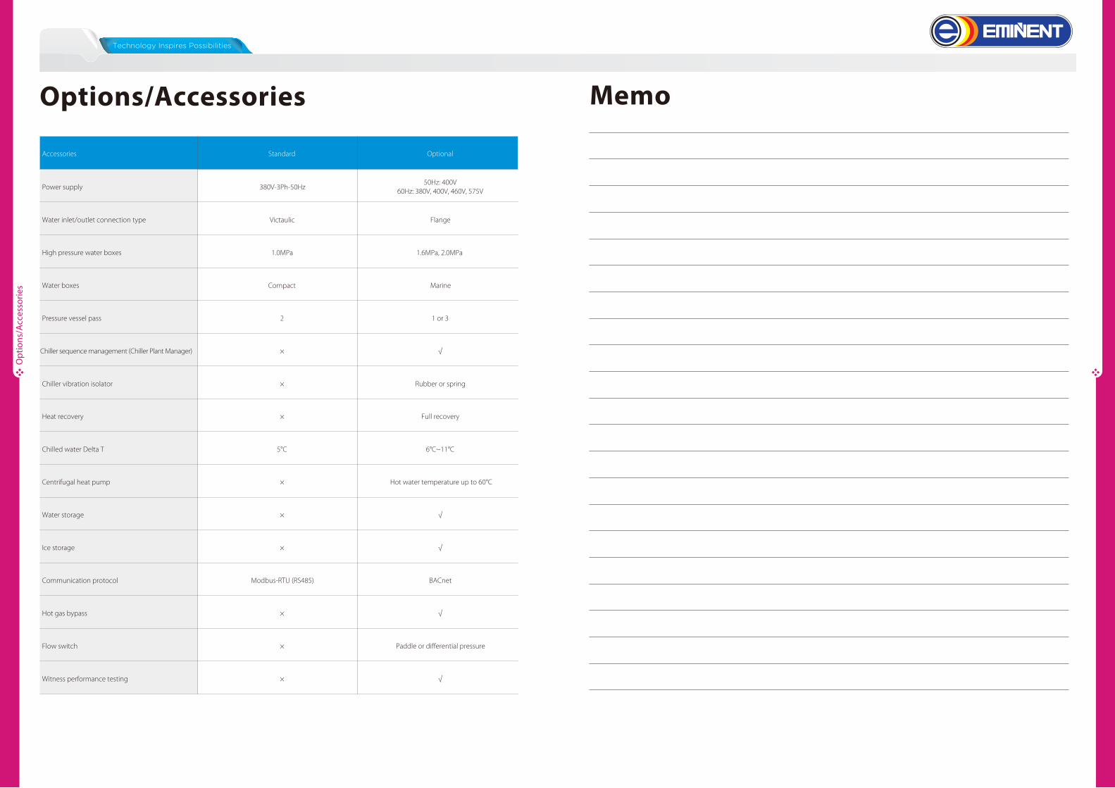
Opt
ions
/Acc
esso
ries
Accessories Optional
Power supply50Hz: 400V
60Hz: 380V, 400V, 460V, 575V
Water inlet/outlet connection type Flange
High pressure water boxes 1.6MPa, 2.0MPa
Water boxes Marine
Pressure vessel pass 1 or 3
Chiller sequence management (Chiller Plant Manager) ×
Chiller vibration isolator Rubber or spring
Heat recovery
Chilled water Delta T
Centrifugal heat pump
Water storage
Ice storage
Communication protocol
Hot gas bypass
Flow switch
Witness performance testing
Standard
380V-3Ph-50Hz
Victaulic
1.0MPa
Compact
2
√
×
×
5°C
×
×
×
Modbus-RTU (RS485)
×
×
×
Full recovery
6°C~11°C
Hot water temperature up to 60°C
√
√
BACnet
√
Paddle or differential pressure
√
Options/Accessories Memo