emp-7300 service manual
DESCRIPTION
EMP-7300 Service ManualTRANSCRIPT

EPSON EMP-7300Service Manual Revision: 3 Jun 1998
Epson (UK) Ltd. 1998 Page: 1 of 1
EPSON ®
Front Cover
Introduction
Precautions
Index Pages
Specifications Section
Back Cover
Goto:-
Spares Guide
Select:-
? << <
Chapter 1Product Description
Chapter 2Theory of Operation
Chapter 3Disassembly & Assembly
Appendix
Notes:-• Detailed circuit board component
diagrams may be found in theAppendix section of this manual.
EPSON EMP-7300

EPSON DATA PROJECTOR
XGA Data Projector
SERVICE MANUAL
EMP-7300
EPSON

INTRODUCTIONThis Service Manual describes of the hardware information which is necessary forthe smooth field service of the XGA DATA PROJECTOR EMP-7300 and the troubleshooting.As the primary technologies will be supplied with the service bulletin, you may updatethis manual.
HOW TO USE THE SERVICE MANUALSince the service manual describes the topics, which may be required in the fieldmaintenance, you may utilize this for repair or diagnosis of failures. The contents areas following. Before you start the maintenance service, read every safetyprecautions and observe safety precautions and observe safety rules. Precautions : SAFETY, MAINTENANCE, and PERSON Chapter 1: GENERAL (PART NAME, SYSTEM FUNCTION, SPECIFICATION, etc.) Chapter 2: THEORY OF OPERATION (HARDWARE, INTERNAL CONNECTION,
and FUNCTION OF UNITS, etc.) Chapter 3: DISASSEMBLE & ASSEMBLE (ASSEMBLY PROCESS FOR MAIN
FRAME) Chapter 4: TROUBLE SHOOTING Appendix: PARTS LIST, EXPLODED DIAGRAM, CIRCUIT DIAGRAM,
HARDWARE COMPARISON TABLE, etc.
VCCI RADIO FREQUENCY INTERFERENCE SELF RESTRICTIONThis product is the type 1 information equipment and uses radio frequency energyand fully complies with the limits for the specifications in the computer informationequipment radio interference regulation (VCCI rules). If not installed and usedproperly manufacturer's instructions, may cause interference to radio and televisionreception.
TRADEMARKIBM and DOS/V are the trademark or the registered trademark of InternationalBusiness Machines Corporation.Macintosh and Power Book are the registered trademarks of Apple Computer Inc.Windows is the trademark of Microsoft Corporation.EPSON is the trademark of SEIKO EPSON CORPORATION.
NOTICES1. This document should not be reproduced in whole or in part without the written permission of SEIKO
EPSON CORPORATION.2. Any of description in this document is the subject to change without notice in future.3. The information and specification in this document are the most up-to-date at the time of publication.
However, we are unable to guarantee the accuracy of printed material after the date of publication. Incase of any mistake or lack of description, please kindly notify us to correct.
4. Any influence by utilizing the document may be out of our responsibility regardless the item 3 above. © 1998 SEIKO EPSON CORPORATION

Record of Revisions
History Issued Date Alternation
REVA 1998,February.13 Preliminary Issued
Memo Random
Free area to memorize any important technical information here.

PRECAUTIONS
1. MAINTAIN THE SAFETY OF OPERATORS
(1) PROTECTION FROM ELECTRIC SHOCK* Whenever doing any repair work on the product, be sure to turn off the powerswitch and remove the electric power cable from the electrical outlet.
* Whenever inevitably turning the power on to the product opening the case or cover(repair process) be sure to take off any metallic materials such as a watch, cuffs,rings, and tie pins which may touch the metallic part of the product and dangerousof electric shock.
(2) PROTECTION FROM ACCIDENTAL INJURY* Be sure not to touch the lamp inner housing and its circumstances after the poweris turned off, they may be heated up even after the cooling down process wasended. Also make sure not to touch the light source and its circumstances duringthe operation of repair as turning the power on.
* Make sure to protect your hands by gloves from sharp edges during assembly anddisassembly.
* Do not look into the light source or lens while the light is on. Protect eyes frombeing damaged.
(3) PROTECTION FROM ACCIDENTS* Any operation should be done while the device placed on a flat and stable place toprevent the device or parts from being dropped. Be careful not to place tools andparts on the device or at your feet.
* Whenever doing any repair work on the product, be sure to away from a place forforeigner come across in order to prevent the product from being used inincomplete condition or accidental near miss. Be sure not to leave the productduring any repair work.
* Be sure to use attached power cable when you supply the power to the product.
2. SAFETY MAINTENANCE
(1) ELECTROSTATIC DISCHARGE* Whenever doing any repair work on the product, be sure to wear the wristband andthe electrostatic mat with grounding. When replacing any electric components(Boards and Optical engine), it is recommended to touch the electrostatic plasticbag of the component to the metallic part of the product once before take thecomponent out from the plastic bag.

(2) LIMITATION OF PARTS* Use only authorized or supplied parts from EPSON for the replacement ofmechanical parts including the lamp inner housing, fuse, air filter and so on.
* Use only the power cable and the interface cables attached with the product.
(3) Others* Visually checks the distortion or dirt at the connectors of the power cable. If dirty,clean off, and if distorted, replace the cable in order to avoid firing by the flush overphenomenon.
* When plug the internal connector cables or the interface cables, be sure to fully pluginto the connectors until it stack to the connector edge.
* When remove the FPC cable of the light valve are sure to remove the connector lockin advance. The connector lock should be unlocked by pulling up the both end ofconnector lock simultaneously with tweezers.
* Whenever doing removal of parts or repair work on the product, make sure that thework is done in a clean room, free of dust and dirt in order to keep the opticalelement away from dirt.
3. REQUIREMENT FOR THE MAINTENANCE PERSON
Authorized person should have the following knowledge and skill for the maintenanceof EMP-7300.* Need to be trained by EPSON authorized maintenance training program and to beauthorized as a service engineer.
* Need to sufficiently understand the operation and the descriptions of this servicemanual.
* Need to have the basic knowledge of electricity (safety operation, circuit diagram,electrostatic, and else...)
4. OTHERS
* Any questions on the RS-361/RS-376 maintenance including supply of the serviceparts or contents of the document would like to be contacted to the below address.Any technical information about amendments is occasionally available as the servicebulletin.
SEIKO EPSON CORPORATION4897 OH-AZA SHIMAUCHI,MATSUMOTO-SHI, NAGANO-KEN 390 JAPANTEL: 81-263-47-5603FAX: 81-263-48-5680ATTN: Visual Device Customer Support Group

Contents
Chapter 1Product general
1.1 PRODUCT GENERAL................................................................................ 1-11.2 PART NAME............................................................................................... 1-2
1.2.1 Outside View of Main Frame ............................................................. 1-21.2.2 Inside View of Main Frame................................................................ 1-31.2.3 Outside View of Remote Controller ................................................... 1-7
1.3 CONNECTION............................................................................................ 1-81.3.1 Connecting to a PC........................................................................... 1-81.3.2 Connecting to a Macintosh................................................................ 1-91.3.3 Connecting to a Video source ......................................................... 1-101.3.4 Connecting to an Audio source ....................................................... 1-10
1.4 MAIN COMPORNENT .............................................................................. 1-111.5 SPECIFICATIONS.................................................................................... 1-151.6 INTERFACE SPECIFICATION ................................................................. 1-17
1.6.1 Computer 1/2 .................................................................................. 1-171.6.2 Audio 1/2......................................................................................... 1-181.6.3 Audio Out ........................................................................................ 1-181.6.4 S-Video ........................................................................................... 1-181.6.5 Video............................................................................................... 1-191.6.6 Audio L/R ........................................................................................ 1-191.6.7 Mouse / Com 1/2............................................................................. 1-191.6.8 Receptor ......................................................................................... 1-201.6.9 RGB Video Input (EHQ option I/F)................................................... 1-20
Chapter 2Theory of operation
2.1 HARDWARE............................................................................................... 2-12.1.1 Electrical System Connections.......................................................... 2-22.1.2 Optical System Connections (Optical Engine) ................................... 2-3
2.2 POWER SUPPLY UNIT.............................................................................. 2-52.3 CD10MA BOARD ....................................................................................... 2-82.4 CD10DR BOARD...................................................................................... 2-112.5 SWITCH PANEL....................................................................................... 2-142.6 CD10AU BOARD...................................................................................... 2-152.7 CD10MJ BOARD ...................................................................................... 2-172.8 CD10AJ BOARD....................................................................................... 2-192.9 CD10VJ BOARD....................................................................................... 2-202.10 CD10PJ BOARD..................................................................................... 2-212.11 CD10RC BOARD (RECEPTOR BOARD) ............................................... 2-222.12 SPEAKER UNIT...................................................................................... 2-242.13 LIGHT GUIDE UNIT................................................................................ 2-252.14 LAMP INNER HOUSING ........................................................................ 2-272.15 SENSOR / SWITCH................................................................................ 2-30

2.15.1 Interlock Switch............................................................................. 2-312.15.2 Safety Switch ................................................................................ 2-322.15.3 Lamp House Thermistor................................................................ 2-332.15.4 LV Thermistor ............................................................................... 2-342.15.5 Front Temperature Thermistor ...................................................... 2-35
Chapter 3Disassembly and assembly
3.1 DISASSEMBLY AND ASSEMBLY PROCEDURES .................................... 3-13.2 DISASSEMBLING THE MAIN UNIT............................................................ 3-5
3.2.1 Removing the Lamp Inner Housing ................................................... 3-63.2.2 Removing the Air Filter Frame Unit ................................................... 3-73.2.3 Removing the Upper Case Unit And Handle ..................................... 3-83.2.4 Removing the Switch Panel ............................................................ 3-103.2.5 Removing the Speaker Units Right / Left......................................... 3-113.2.6 Removing the CD10AU Board......................................................... 3-123.2.7 Removing the Receptor Board Assembly (FI Board / RI Board) ...... 3-133.2.8 Removing the CD10MA Board ........................................................ 3-143.2.9 Removing the Rear Case Unit Assembly ........................................ 3-163.2.10 Removing the CD10AJ/CD10MJ/CD10PJ/CD10VJ Board ............ 3-173.2.11. Removing the Lamp Thermistor ................................................... 3-193.2.12. Removing the Prism Duct / LV Thermistor.................................... 3-203.2.13. Removing the Safety Switch......................................................... 3-213.2.14. Removing the Optical Engine ....................................................... 3-223.2.15. Removing the Power Supply Unit / PBS Thermistor ..................... 3-233.2.16. Removing the Foot Adjuster A/B .................................................. 3-253.2.17. Removing the CD10DR Board Assembly ..................................... 3-263.2.18. Removing the FC Board............................................................... 3-273.2.19. Removing the Projection Lens Unit (PLU) .................................... 3-283.2.20. Removing the Cooling Fan / Optical Head Unit / Light GuideUnit/Exhaust fan....................................................................................... 3-29
Chapter 4Troubleshooting
4.1. Before Starting Troubleshooting Procedures.............................................. 4-14.1.1. Tools and Accessories Required for Troubleshooting ...................... 4-14.1.2. Field Replacement Parts .................................................................. 4-1
4.2. Entry .......................................................................................................... 4-2
AppendixParts tableCircuit diagramExploded diagramHardware comparison table

Chapter 1
Product general

1-1REV.A
1.1 PRODUCT GENERAL
EMP-7300 XGA DATA PROJECTOR designed as the full compatible XGA projector isthe maximum luminance device be used the new UHE lamp and the micro lens arraywith XGA resolution to project enhanced color images from the two personalcomputers CRT and any one of video equipment such as video tape deck, videocamcorders or digital camera.
FEATURE OF EMP-7300* Portable light weight, compact sizeThe new type of power unit and circuit board and the simple structure enables tominimize the body in A4 file size with the weight of 6.7kg. An optional carrying casewill be useful in transporting.
* Bright and clear imageThe micro lens array, the new type of UHE-120W lamp (950lm.ANSI) and the optical
block enable to achieve a wide projection image from 30" to 300" (projection distance :1.2 to 12 m). An optional high brightness screen will supply the high brightness even inthe light ambient.* High resolution full color (16770 thousands colors)3 (R, G, and B) of TN liquid crystal panels of 786,432 pixel will supply XGA resolution
of 1024 x768 dots.* Standard attachment of remote controllerThe projector can be controlled using a handheld remote control unit, with menus
being provided for Image source switching and Image adjustment. The remote controlcan also be used as a wireless mouse to control mouse operations on the computerscreen during presentations. The ELP LINK IITM software that comes with the projectorprovides a number of add-on features that are designed to make presentations moreeffective.* Connectivity with various computersThe advanced data signal determination function enables EMP-7300 to connect with
various computers such as IBM-compatible PCs and laptops, Macintosh. It alsodetermines video signal of NTSC, PAL or SECAM in composite video, S-Video format.* Advanced Image Real-time ResizerThe projector also features a new patented AIrRTM (Advanced Image Real-time
Resizer) chip for supporting of miscellaneous computer output, as well as full XGAoutput. No matter what type of output is used, the result is full-size video image ofoutstanding clarity.* Simple MaintenanceThe maintenance easy. Number of image adjustment process is not required.
* Theft - proofKensington lock is available with hole on the lower case.

1-2REV.A
1.2 PART NAME
1.2.1 Outside View of Main Frame
Figure1- 1
Lamp indicator
Temperature indicatorSpeaker
Handle
Foot lever
Remote controller
signal receptorTheft-proof
Focus ring
Zoom ring
Front foot
Operator panel
Resize button
Source button
Menu button
Operation indicator
Sync button
Power button
Blank button
Tracking button
Enter button
Volume buttonMenu button
Operator panel

1-3REV.A
Figure1- 2 Bottom side view
1.2.2 Inside View of Main Frame
Figure1- 3 Inside view of main frame
Power supply unit
Main board
Front foot
Lamp cover
Rear foot
Air filter cover

1-4REV.A
Figure1- 4 side view
Figure1- 5 Under the main board view
Driver board
Light guide unit
Exhaust fanLV Thermister Prism duct Driver board
Inlet unit

1-5REV.A
Figure1- 6 Inside of rear case unit
Figure1- 7 Under the driver board view
CD10AJ board
CD10VJ board
CD10RJ boardCD10MJ board
Foot adjuster A
Light guide unit
Safety switchLamp Thermister Lamp power cable

1-6REV.A
Figure1- 8 Lower case view (Under the light guide block)
Inlet unitFilter cover switch CN board
Filter board Air filter frame

1-7REV.A
1.2.3 Outside View of Remote Controller
Remote controller
Figure1- 11 Remote controller
Menu button
Effect button
Right click button
Custom button
Mute button
Volume button
Source button
Effect button
Pointer button
Blank button
Resize button
Freeze button
Power button
Front view Rear view
Remote infrared Ray
Left click button
Battery cover

1-8REV.A
1.3 CONNECTION
1.3.1 Connecting to a PC
Figure1- 13
Computer cable (Attached Accessory )
Computer 1

1-9REV.A
Switch A
Switch B
MAC Adapter
1.3.2 Connecting to a Macintosh
Figure1- 14* Attached accessoriesÅ ¦ Dip switch settings are required according to the machine type.
Refer to the following table for detail. (Default setting is MAC13 mode.)Table1- 1 MAC Adapter Dip Switch settings
Mode Switch A“ON”
switch B“ON”
VGA 640x480 3,4,5 813” 640x480 1,2,5 816” 832x624 2,4,5 819” 1024x768 2,3,5 821” 1152x870 1,2,3,4,5 813” Multi Res. 1,2,5 814” Multi Res. 1,2,5 3,4,817” Multi Res. 1,2,5 3,8/4,821” Multi Res. 1,2,5 3,8
Figure1- 15 Monitor adapter
Computer 1
Computer cable (Standard accessory)
Mac. Desk top adapter
(Attached accessory)

1-10REV.A
1.3.3 Connecting to a Video source
Figure1- 17 Connection for video source
1.3.4 Connecting to an Audio source
Figure1- 18 Connection for audio source
A/V cable (Attached accessory)
Video Audio L Audio R
Audio out
External audio devices
Audio cable (Consumable)
1-11REV.A
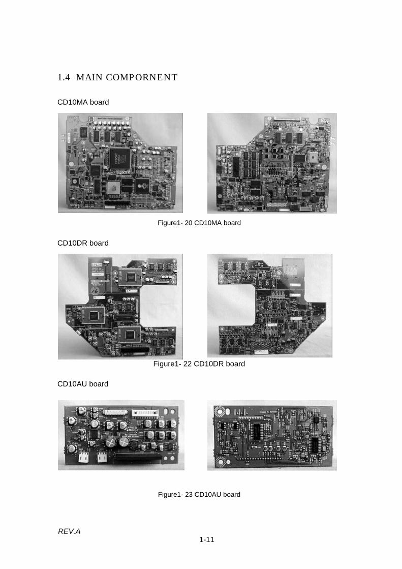
1.4 MAIN COMPORNENT
CD10MA board
Figure1- 20 CD10MA board
CD10DR board
Figure1- 22 CD10DR board
CD10AU board
Figure1- 23 CD10AU board

1-12REV.A
CD10MJ board
Figure1- 26 CD10MJ board
CD10AJ board
Figure1- 27 CD10AJ board
CD10PJ board
Figure1- 28 CD10PJ board
CD10VJ board
Figure1- 29 CD10VJ board

1-13REV.A
Power supply unit
Figure1- 30 Switch panel
Switch panel
Figure1- 31 Switch panel
(15) Optical engine
Figure1- 32 Optical engine

1-14REV.A
Receptor board
Figure1- 33 Receptor board
Receptor boardReceptor board

1-15REV.A
1.5 SPECIFICATIONSTable1- 2 specifications
OPTICAL FEATURESDisplay method Poly-silicon TFT (MLA built) color liquid crystal display
(R/G/B three panels)Full lines, twelve phase block series
Optical method Dichroic mirror separation and prism combine methodProjection image size Minimum 30 inch to maximum 300 inchProjection distance 1.2 m to 12 mResolution 1024 x768 dots, 2,359,296 pixels (786,432 x 3)Projection Lens Zoom lens F2.0 - 2.3 (55-72 mm)Focus adjustment ManualZooming adjustment Manual(1:1.3)Light SourceLife(Lamp inner housing)
120 W (AC drive)UHE lamp,(type ELPLP05)2000 hours at 50% brightness
Average iluminance Typical:950Lm(ANSI), Average:85% of typicalAUDIO FEATURES
Output for internal speaker Dynamic speaker(3W-8Ω) x 2 (stereo)Audio out Interface External speaker 3.5mm Stereo mini-jack
Internal speaker output is stopped when mini-jack isplugged.Output signal:0 to 500mVrmsload imperdance:600Ω
Audio L/R interface(For Video device )
Audio signal(stereo) from the video devices. Input interfaceis separated with R(Right) and L(Left).Interface type:RCA jackInput signal:500mVrms
Audio 1 interface(For Computer 1)
Host computer 1 Audio input (stereo)Interface type:3.5mm Stereo mini-jackInput signal: 500mVrms/47KΩ
Audio 2 interface(For Computer 2)
Host computer 2 Audio input (stereo)Interface type:3.5mm Stereo mini-jackInput signal: 500mVrms/47KΩ
REMOTE CONTROLWireless remote controller For controlling EMP-7300 operating mode and controlling
host computer from EMP-7300.Signal is detected with internal receptor board.Control range: Within 10 m and 30 degree wide (right/left),15 degree wide (upper/lower) from receptor of LCP.
VIDEO INPUT/OUTPUTComputer 1 interfaceComputer 2 interfaceS-Video Interface
Host computer RGB outputInterface type: HD-15pin(DDC1/2B compatible)Input signal: Luminous 0.714Vp-p,Chrominous 0.284Vp-p.Interface type: Min-DIN 4pinS-Video is prior to composite video.
Video Interface(Composite video interface)
Input signal: 0.7Vp-p, 75Ωsync: negative 0.3Vp-pInterface type: RCA jackTV signal type: NTSC 3.58MHz AL 4.43MHz SECAM 4.43MHz Auto identification(Default)

1-16REV.A
MOUSE/COM 1/2 Auto identification (Mouse or RS-232C)
Serial Mouse or RS-232C Interface type: DIN 13pin
COMPONENT VIDEO INPUT(For EHQ option interface)This interface is as RGB video inputterminal as well,then distinguish thesignal classification automatically.
Input signal: 0.7Vp-p, 75Ωsync: negative 0.3Vp-pInterface type: BNC jack
Y :Commonjack as Video In GR-Y:Commonjack as Video In BB-Y:Commonjack as Video In R
POWER SUPPLYInput Voltage AC100-120V /200-240V ±10% (50/60Hz)Power Consumption Approx. 260 W (Standby mode:30W)
300 mm (W) x 120 mm (H) x 363 mm (D)Dimensions300 mm (W) x 129 mm (H) x 400 mm (D)include foot adjuster and lens.
Weight Approx. 6.7 kgENVIRONMENT
Operational temperatureStorage temperature
+5 to +40 degrees centigrrate-10 to +60 degrees centigrrate (non condensing)
Operational humidity/ Storage humidity 20% to 80% / 10% to 90% (non condensing)Operational/storage Altitude 3048m / 6096m

1-17REV.A
1.6 INTERFACE SPECIFICATION
Figure1- 35
1.6.1 Computer 1/2
Computer video input D-SUB 15 (HD)
Pin Terminal Pin Terminal1 Red video 9 +5V2 Green video 10 Synchronous GND3 Blue video 11 Monitor (ID bit 0)4 Monitor (ID bit 2) 12 SDA5 GND 13 Horizontal synchronization6 Red video GND 14 Vertical synchronization7 Green video GND 15 SCL8 Blue video GND
1510 6
1115

1-18REV.A
1.6.2 Audio 1/2
Stereo mini jack with 2 circuits for detection pin(The detection pin which is not required for audio input, is equipped for audio outterminal.)
1 pin: GND2 pin: Computer audio input L3 pin: Computer audio input RThe other pins: NC
1.6.3 Audio Out
Stereo mini jack with 2 circuits for detection pin
1,4 pin: GND2 pin: Audio output L 3 pin: Audio output R5 pin: Detection of Line-out jack insertionThe other pins: NC
1.6.4 S-Video
Mini DIN 4-pin with a detection pin
1,2,6 pin: GND3 pin: Y signal input4 pin: C signal input5 pin: Input detection terminal
Å H
Å H
Å H
Å H
Å H
Å H
Å H
Å H
Å H
Å H
Å H
Å H
Å H
Å H
Å H
Å H
Å H
Å H
4
2
3
1
56
1-19REV.A
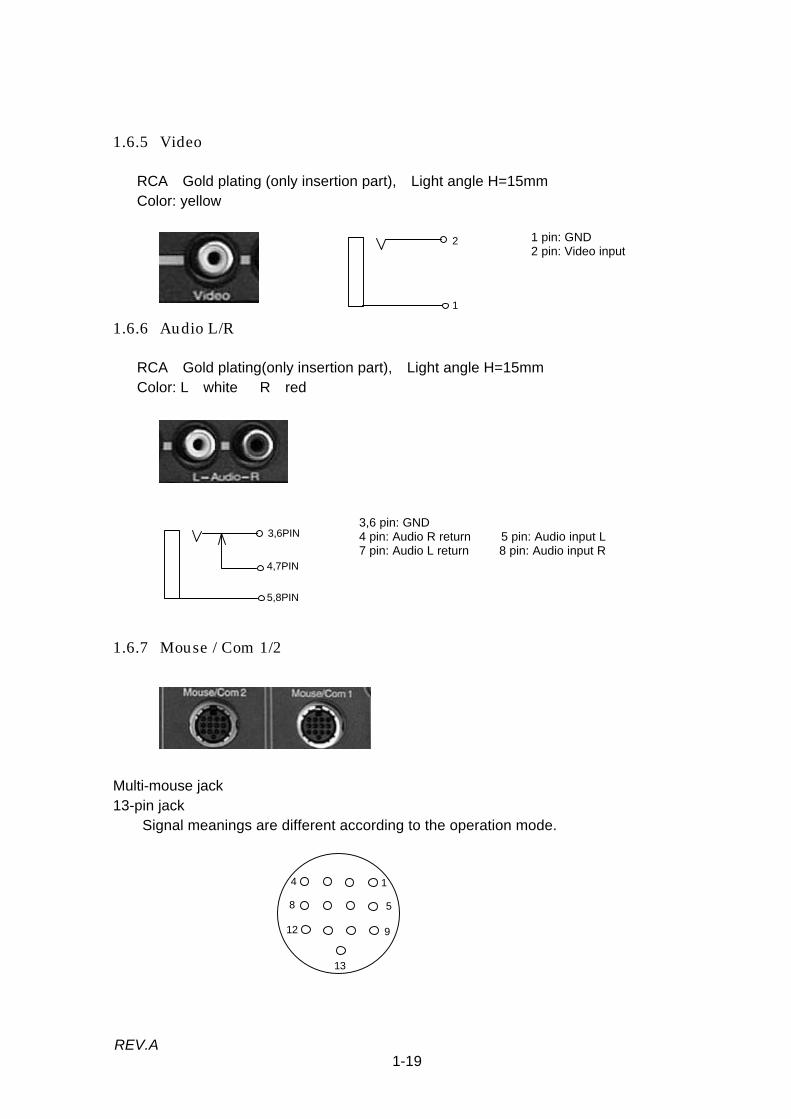
1.6.5 Video
RCA Gold plating (only insertion part), Light angle H=15mmColor: yellow
1 pin: GND2 pin: Video input
1.6.6 Audio L/R
RCA Gold plating(only insertion part), Light angle H=15mmColor: L white R red
3,6 pin: GND4 pin: Audio R return 5 pin: Audio input L7 pin: Audio L return 8 pin: Audio input R
1.6.7 Mouse / Com 1/2
Multi-mouse jack13-pin jack Signal meanings are different according to the operation mode.
2
1
3,6PIN
5,8PIN
4,7PIN
4
8
12
1
5
9
13

1-20REV.A
Pin PS/2Mousel
98Mouse
Mac.Mouse
SerialMouse
PC serial/Mac.serial
1 XA XA XA Reserved Reserved2 XB XB Reserved Reserved Reserved3 Reserved YA Reserved TXD Reserved4 Reserved YB Reserved READY Reserved5 LEFT LEFT Reserved GND Reserved6 Reserved RIGHT LEFT GND Reserved7 Reserved Reserved Reserved GND Reserved8 Reserved Reserved Reserved Reserved TXD9 Reserved Reserved Reserved Reserved RXD10 Reserved Reserved Reserved Reserved DTR11 Reserved Reserved Reserved Reserved DSR12 PCV(+5V) PCV(+5V) PCV(+5V) Reserved Reserved13 GND GND GND GND GND
1.6.8 Receptor
1.6.9 RGB Video Input (EHQ option I/F)
2
1
PIN: GNDPIN1: GNDPIN2: Serial Data

Chapter 2
Theory of operation

2-1REV.A
2.1 HARDWARE
The hardware of EMP-7300 XGA data projector is distinguished in the optical systemand the electrical system.The lower level beyond the breaking line in the Figure2-1 show the optical system,and the upper level shows the electrical system.
Figure2- 1 Optical system block diagram(Projection process outline)1. Digital or analog R/G/B signal is provided from a computer 1 or 2 to the CD10MA
board through CD10PJ board. Analog signal (S-Video or Video signal) is provided tothe CD10MA board through CD10VJ board. (Analog signal should be oncechanged into digital signal by the CD10MA board.)
2. Video signal (digital) is once stored in the video memory (SRAM) on the CD10MAboard , then the CD10DR board generates signals to drive the light valves R/G/B.
3. The light valves R/G/B are individual panels each others. LCD driver signalsgenerated CD10DR board drive LCD shutter. (They work to shut or transmit thelights from the light guide unit.)
4. The lights transmitted through the light valves will be combined the prism andprojected through the projection lens unit.
Note *1: Cooling fan cools the light valves of R/G/B (LCD panel)Note *2: Exhaust fan exhausts mainly the heated air around the light source.Note *3: Blower fan exhausts mainly the heated air in the power supply unit.
CD10MJ
CD10PJ
CD10AJ
CD10VJ
CD10DRBOARDGenerate theR/G/Bvideo signal andoutput to theLight valves.
CD10MA BOARDConduct setting of theinitial operation of circuitand control thecomputer interface.Conduct the internalcontrol(Sensor, Fan, Speaker,
Switch Panel)
POWERSUPPLYUNITGenerates DCvoltage(+5V,+12V,+22V,+3.3V)for the electriccircuit.Generates ACvoltage for theLight Source.
COOLING FAN *1SWITCH PANEL
BLOWER FAN*3 PROJECTIONLENS UNITFocus/Zoom
Audio Out
Video in
S-Video
Computer 1/2
Mouse/COM1/2
OPTICALHEAD UNIT(Polarizationplate / Lightvalve R/G/B)
PRISMR/G/Bcomposite
EXHAUST FAN *2
LIGHT GUIDE UNITDivide the light Into 3(R/G/B) by Lens,filter, and Mirror
LAMP INNERHOUSINGUHE 120W(Light Source)
R/G/B/BNC/HD/VD
Audio 1/2

2-2REV.A
2.1.1 Electrical System Connections
Electrical units of EMP-7300 are physically connected mainly to the CD10MA board asshown below.
Figure2- 2 EMP-7300 Hardware connection
Lamp Thermister
Thermister
Power unit fan
CN500
CD10MJ boardCooling fan
CD10RC board
CD10RC board
LV Thermister
CD10FC board CD10FU board
CN103
CN100
CD10AJ boardCN301 CN300
CN101
CN100CN620(IN-FAN)
CN902(MOUSE) CN401(S-DET) CN800(IF-B)
CN201(PC-IN)
CN200(PC-SYN)
CN901(R-RC)
CN622(EX-FAN)
CN651(LAMP-TH)
Lamp
CN621(LAMP-FAN)
CN600(PS)CN650(AIR-TH)
CN652
CN400(SW)CD10MA board
Power supply unit
CN104CN700
CN800
CD10DR board
CN900
CN100(Fuse)Lamp inner housing
Speaker R
CD10VJ board
CN402(AU)
CN203CD10PJ board
CN204
CN900(F-RC)
Speaker L
CN100
CN103CN102
CN101CD10AU board
Fan
Exhaust fan

2-3REV.A
2.1.2 Optical System Connections (Optical Engine)
The optical systems consists of 5 blocks (Exhaust fan, Light guide unit, Opticalhead/Prism unit, and Projection lens unit) as shown below. These units and CD10DRboard are specified as “Optical engine” and it is one replaceable part.In addition to the five items, CD10FC board is attached at the bottom of light guide unit.It relay the switch signal on the lamp inner housing to the CD10DR board. It istherefore independent of the optical functions.
Figure2- 3 Optical block
(Inside view of light guide unit)
Figure2- 4 Inside of light guide unit Figure2- 5
Lamp inner housingMounting position
Projection lens unitOptical head/Prism unitLight guide unit
FC board
Exhaust fan

2-4REV.A
Caution:Take care not to cause any shock or mechanical stress to the optical engine and alsonot to disassemble it. Otherwise, the pixel divergence may occur.The alignment adjustment for each other is applied in the factory, and also electricalcorrection is applied with CD10DR board according to the each optical engine.Therefor do not separate or exchange the each unit to the others.
Table2- 1 Unit functionUNIT NAME FUNCTION & REMARKS
LAMP INNER HOUSING Include one UHE LAMP as a light source.CD10FU board is mounted for lamp inner housing detection.
LIGHT GUIDE UNIT Disperse the light from the light source and uniform by the lens array A/B.(Ultraviolet ray also eliminated.)Disperse the light in three (R/G/B) factors, with condensor lens and mirror.
OPTICAL HEAD/PRISM UNIT
Consist of three light valves, polarization plate and prism unit.Each light valve controls shutter of pixels with twelve levels.Prism unit composes R/G/B optical signals and transfers to the projection lensunit.
Caution:Exhaust fan, Light guide unit ,Optical head /Prism unit, Projection lens unit andCD10DR board are treat as one parts named Optical engine.

2-5REV.A
2.2 POWER SUPPLY UNIT
The Power Supply unit includes DC regulator, blower fan and interlock switch withlamp cover.The Power Supply unit generates the voltage for the control circuit (+3.3V,+5V, +12V,+22V) and for the ballast (AC power) from AC inputFront temperature thermistor is installed on the side of the power supply inhale fanand is retained with a clamp on the power supply unit. It detects the temperature, if itsenses overheat, it shuts off the regulator output via the CD10MA board.Although the outline of its function is shown below, please never disassemble thepower supply unit at the field maintenance service.
Figure2- 6 Power supply unit
(1) Function block
Figure2- 7 Function block
REGULATORFILTER/
RECTIFIRE
+12V
+22V
+5V
ACLight sourcelamp
BLOWER FAN
SAFTY SW
POWER CONTROL
INTERLOCK SW
AC IN
N/CN/C
+3.3V
Front temperatureThermister
CD10MABOARD
CN600
Connect toCN600 on theCD10MA board(DC output andpower control signals)
Interlock switch
Power cable forlight source
Front temperature
Inhale fan

2-6REV.A
* The input signal from the safety switch is prepared for the protection of over heat. Itshuts the supply of AC power with overheat condition. Safety switch is mounted onthe light guide unit closed to the lamp inner housing.
(2) Outline of function* The Interlock switch is built for the safety purpose.* The Interlock switch is accordingly work with the lamp cover at the bottom of mainchassis. It is normally at the ON position. It will shut the AC power by opening thelamp cover.
* The cable of the power supply unit is connected to CN 600 on the CD10MA board.Additionally, the following voltage and signal are connected to CN 800(801):
DC output (+3.3/+5/+12/+22V),PWDS signal for the power down detection,PWON signal for power on/off.Lamp status signal (LPST),Power on/off signal (BACT).
Caution:If the AC power cable is still connected after the power is shut off, +3.3V backgroundvoltage is supplied to the CD10MA board via CN 600. The background voltage issubsequently supplied to the power on/off circuit.
* The filter/rectification circuit work to neglect noise on the AC line and generate DCvoltage for the regulator.
* The regulator generates the various level of DC voltage as shown in the below tablein the switching regulator. The regulator detects the voltage output level at the +5Vline and feed back to the switching circuit to maintain the output level stableregardless the load variation.Each output voltage level is not the subject of adjustment.
Table2- 2 Output specificationsPower source +5V +3.3V +12V +12FV +22V
Output voltage accuracy (%) ±5 ±5 ±5 12.0-13.8V 19.0-24.0VRipple (mV p-p) 200 100 100 400 400Ripple/ Spike(mV p-p) 200 100 100 400 400Output current Min(A) 1.0 0.3 0.2 0.05 0.0 Rated (A) 2.4 2.0 1.0 1.5 0.3 Peak(A) - - - 2.0 -Overvoltage protection +7V +4.6V - +16V +30VOvercurrent protection Transient
(Note)Distortion Distortion Transient
(Note)Transient (Note)
Use Logic circuit Logic circuit Analog circuitfor LCD
Fan/Audiocircuit
Light valves
NOTE : Protection is the transient detection type, it is recoverable with power on.

2-7REV.A
* The blower fan (connect to the CN622 on the CD10MA board) is built for exhaustingthe heat generated in the power supply unit. The heat exhausted by the blower fan willbe exhausted outside by the exhaust fan which is connected to the connector CN 621on the CD10MA board.
(3) Pin assignment on the CD10MA board connector CN 600
Table2- 3 CN600Pin .No Signal
1 +5V_S2,3 +5V4,5 3.3V6,7 12V_F8 PWDS9 PWON1 to 12 L GND13,14 A GND15 -12V16 +12V17 +22V18 L GND19 LPSTC20 BACTA
Figure2- 8
PIN 20PIN 1 CN600

2-8REV.A
2.3 CD10MA BOARD
The CD10MA board controls the center of the product. It consists of CPU, P-ROM,video memory(SRAM), digital video controller, and circuits for switch panel control,computer in 1/2 interface control, display output control, power management control,and etc...The CD10MA board controls everything except to generate and audio output thedisplay signal. The CD10MA board is available as a unit for the service parts.
Figure2- 9 CD10MA board
Figure2- 10 CD10MA board
2-9REV.A
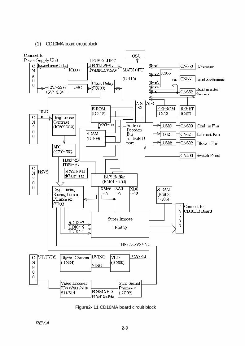
(1) CD10MA board circuit block
!"
"
##$!"%
$##&!
'' ((' )*(+ ), +
-$!"
$!.
/+(()+ (+.)"
0 &1$(234111'3+"
*, 1,(
*55 !"!!
$"%%
-$%
678.
+ / 18!
8
6' #' 8)88)8")8"")8"!
((
" "
!
+ + *,, +
)71,+
9"6):6):6):%0%6
7 #)77#)7&7)77;&);6
$40
<)6
#=/*(+
+/
>8"
>
>"
+ +"$ '
$4
<?)6?
% 64
?4
<)6<)6)$4)+0
?))6
%%
Figure2- 11 CD10MA board circuit block
6

2-10REV.A
(2) Outline of function
1. Main CPU / SRAM and related circuits are backed up with +3.3V which providedfrom power supply. (If the AC cable is connected to the AC source, power supplyprovides the +3.3V for back-up bias even if the power is turned off condition.)
2. When the power is turned on with power button on the switch panel or remote tocontroller, CD10MA board generate the reset signal and initialize the circuit, andthe CPU reads the program from F-ROM and write it into SRAM (IC409). Then theCPU sets functions according to the program and indicates the initial image.
3. Three thermistors (LV Thermistor / Lamp House Thermistor / Front TemperatureThermistor) detects temperature. If the temperature exceeds certain degrees, thethermistors signal generates interrupted signal to the main CPU and shut off thepower supply regulation.
4. CN200 display input signals (Analog or digital) are converted into analog signal atfirst, then converted to digital again with ADC.These display data are write into the video memory (SRAM).
5. To display the data , received data are stored into the SRAM (IC300 to 305), thenread out to the video controller via Super Impose (IC502). Digital video controllergenerate the display control timing and send to the CD10DR board.
6. The EEPROM (IC413) and timer circuit provided the operating time control of thelight source bulb (lamp inner housing). It’s operation is described below.
Table2- 4Light source state Lamp monitor state
When the operating time of the light source bulb(lamp inner housing) exceeds 1900 hours.
The lamp monitor continues to flash red and orangefor 5 minutes after it is turned on. (The light sourcestays on)
When the operating time of the light source bulb(lamp inner housing) exceeds 2000 hours.
The lamp monitor lights in red.
When the light source bulb (lamp inner housing)runs out before it’s life.
The lamp monitor lights in red.
If the above phenomenon is observed, it is necessary to replace the light source bulb(lamp inner housing)Then please turn on the switch. The fuse involved in the lamp will melt and short outso that lamp timer will be reset automatically.
The temperature detection circuit (three of thermisters) the section is more thancertain degrees, the circuit causes an interrupt to the CPU, then shut the power supplyregulation.

2-11REV.A
2.4 CD10DR BOARD
The CD10DR board has two functions, one is for converting the R/G/B display signalfrom the CD10MA board into twelve states of analog signals (light valve driver signals)and another is for controlling the display image by referencing electrical correctiondata.
Figure2- 12 CD10DR board
Figure2- 13

2-12REV.A
(1) Outline of function
1. CD10DR board generates analog display signals for the light valve driver. DAC(digital signals converted into analog signals) , level shifter circuit for bios circuit /timing control, and interface connector connected to the light valve are installed onthe board.
2. The signals RD(0~7)/GD(0-7)/BD(0-7) output from the CD10MA board are onceconverted into analog signals by the D/A before output to the video amplifier drivercircuit (IC700 to 702, 800 to 802, 900 to 902) for light valves.
3. The timing signals (Hsync, Vsync etc..) output from the display controller are twelvechannels DAC generated signals for R, G, B again, then the signals output to thelight valves (LCD) via level shifter circuit.
4. Brightness is done that bios (R/G/B) generated from twelve channels DAC control,then changing each analog signals output level (R/G/B) of video amplifier circuit.
5. The flash ROM contains electrical correction data for image display. Correction dataare read by display controller on CD10MA board. And use for display timinggeneration, brightness / contrast / chroma and density control.
6. Parameters read from flash ROM are read to CD10MA board, then send to twelvechannels DAC on CD10DR board by serial data, and control the display signals andthe timing signals.
7. Video amplifier circuit convert the input analog signals to the LCD (Liquid CrystalDisplay) driver signals.

2-13REV.A
(2) Circuit block diagram of CD10DR board
Figure2- 14
CN103
IC200
IC250
IC300
IC900/901/902
Video Amp
IC800/801/802
Video Amp
IC700/701/702
Video Amp
CN900BLUE
CN800GREEN
CN700RED
REDLEVELSHIFTER
GREENLEVELSHIFTER
BLUELEVELSHIFTER
F101 REGULATOR
F100 REGULATOR
REGULATOR
REGULATOR
REGULATOR
REGULATOR
BIAS CONTROL
GD0 to 7
BD0 to 7
CLK/SCL/SDACLR/HSYSC/VSYNC
RA1 to 12/RBIASRDYDIR/CLY/CLX/DX/DY/ENB/NRG
GDYGA1 to 12/GBIAS
BDYBA1 to 12/BBIAS
P12V
P5V
P22VVDDY
P3V VDDY
P15V
-9V
M12V
RGB BIASBIAS COM
R G B
RD1 to 12 GD1 to 12 BD1 to 12
RD0 to 7
DAC(12)Channel
CN100CD10FC
FLASH ROMSCL/SDA

2-14REV.A
2.5 SWITCH PANEL
This panel includes the board with 13 switches, and is connected to the connector CN400 on the CD10MA board.
Figure2- 15 Figure2- 16

2-15REV.A
2.6 CD10AU BOARD
CD10AU board includes audio controller (IC105), 3D effector (IC102/104), amplifier(IC107) and connector for internal speaker.3D effector receive input audio signal (Audio1/2, Video audio) from CD10AJ board,then output internal speaker or Audio out (internal speaker via CD10AJ board) viaamplifier circuit.The audio controller control volume (include MUTE) based the serial data (SDA/SCL)output from CD10MA board.The audio signal interfaces controlled CD10AU board are shown below.
(1) The voice generated from CD10MA board. (Waning voice etc.)
(2) - Audio In 1 (for computer 1) - Audio In 2 (for computer 2)
- Audio out (for outside sparker output)
(3) - S-Video (Super impose video input)- Video In (Video device image data input)- Audio In L (Video device audio L input )- Audio Out R (Video device audio R input)
Figure2- 17 CD10AU board
Figure2- 18 CD10AU board

2-16REV.A
The CD10AU board circuit block is shown below.
Figure2- 19 CD10AU board circuit block
Audio input signals from computer 1/2 (via Audio In 1/2) or from a video device (viaAudio In L/R) are first input to the 3D effector and amplified by the sound preamplifier,then output to the “Audio Out” interface or the built-in speaker through the 3D effectoragain.The sound controller performs the audio-signal output selection based on the SCL /SDA (serial data / clock) signals provided from the CD10MA board.
(CONNECT TOCD10MA BOARD CN402)
SPEAKER L
SPEAKER R
CN100
IC102 PREAMPLIFIER
IC105AUDIO CONTROLLER
IC1043D
EFECTORAMP
IC107 AMPLIFIERONTIME IN1/2
CN102BV REGULATOR
CN101
IC603
IC106
CN103
(CONNECT TOCD10AJ BOARD CN301)
Audio L/RLine Out L/R
SW 1/2
LINE OUT DETECTSCL/SDA
RESET
MUTE

2-17REV.A
2.7 CD10MJ BOARD
CD10MJ board includes the board for connecting a remote control receiver and themouse / serial interfaces of a host computer. The electric current control resistanceand the noise filter circuit are only installed on the board. CD10MA board controlsswitching and other things.CN 101 (Mouse / Com 1) and CN 102 (Mouse / Com 2) are multi-mouse connectors. Ifthe ELP communication kit 2 option is installed on the host computer and cables areconnected to them, host computer control is available from remote controller. Thecontroller on the CD10MA board automatically determines the interface operationmode to apply the proper circuit to them.The optional remote control receiver can be connected to the receptor interface (J101).The receiver provides the same functions as the standard receptor board (FI / RIboard). Without the receiver the remote controller is enabled to use within the limitedarea in front and rear. The receiver expands the controllable range for the remotecontroller.
Figure2- 20 CD10MJ board
Figure2- 21 CD10MJ board

2-18REV.A
The CD10MJ board circuit block shown below.
Figure2- 22 CD10MJ board circuit block
You must use the cable appointed our company for Mouse/COM interface. Exclusiveconnector cable is not only connect signals but also connect to ground line in part andreturn to the other signal line inside.
J100
CN100
CN101
CN102
Mouse/Com1
Mouse/Com2
Repeater

2-19REV.A
2.8 CD10AJ BOARD
CD10AJ board includes Audio 1/2 and Audio out interface connector. The noise filtercircuit and switching circuit of Audio 1/2 are installed on the board. The switchingcircuit connect to the audio signals (S-Video) from CD10VJ circuit and select the audiosignals, then output the audio signals amplified CD10AU board.
Figure2- 23 CD10AJ board
Figure2- 24 CD10AJ board
Figure2- 25 CD10AJ board circuit block* When the outside speakers connect to Audio out, Line Out Detect signal is ON, thenstop audio output to the internal speaker connected CD10AU board controlled byCD10MA board.
IN1
IN2
CN300
IN2
IN1
CN301
Audio1
Audio2
Audio Out
J300
J301
J302
Filter circuit
Filter circuit
Filter circuit
IC300 SelectorIN3
IN3
IC301 Selector
Connect to CD10VJ board
Line Out R
RL
RL
DETRL
Audio L
Audio R
Line Out L
Line Out Detect
Connect to CD10AU
2-20REV.A
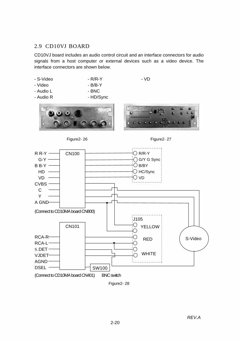
2.9 CD10VJ BOARD
CD10VJ board includes an audio control circuit and an interface connectors for audiosignals from a host computer or external devices such as a video device. Theinterface connectors are shown below.
- S-Video - R/R-Y - VD- Video - B/B-Y- Audio L - BNC- Audio R - HD/Sync
Figure2- 26 Figure2- 27
Figure2- 28
R R-YG-Y
B B-YHDVD
CVBSCY
A GND
CN100 R/R-YG/Y G SyncB/BYHC/SyncVD
CN101
J105
RCA-RRCA-LS. DETVJDETAGNDDSEL
YELLOW
RED
WHITE
S-Video
SW100
(Connect to CD10MA board CN800)
(Connect to CD10MA board CN401) BNC switch

2-21REV.A
2.10 CD10PJ BOARD
CD10PJ board includes computer input interface (Computer1/2) and RGB monitoroutput interface (Computer Out). The noise filter circuit and the output circuit to RGBmonitor are installed on the board.
Figure2- 29
Figure2- 30
Figure2- 31
Computer 1
(RGB Input 1)
CN200
Computer 2
(RGB Input 2)
Computer Out
(RGB Output)
CN201
CN202
Filter circuit
Filter Circuit
IC203
IC206
IC207 CN203
CN204
IC204
R-ING-INB-IN
(Connect to CD10MA board CN201)
(Connect to CD10MA board CN200)
PCHSPCVSCP05/07+5V/GNB
RGB

2-22REV.A
2.11 CD10RC BOARD (RECEPTOR BOARD)
This is the board with the infrared signal detection component. There are two receptorboards equipped in this device, one is attached to the speaker bracket on front face(Front), another is on the rear case (Rear). You can control this device through theboards on both sides. There are used same boards.
The figure 2-32 to2-33 shows the receptor boards and their circuits.
Figure2- 32
Figure2- 33
Each receptor board is connected to CN 900(Front)/901(Rear) on the CD10MA board,its output signal (serial data) is connected to I/F control CPU after wired OR is appliedon CD10MA board.
1. The CD10MA board performs the power ON/OFF operation and the starting upmenus, utilizing the serial data received from the remote controller (button switchesand pointers).
2. The serial signal send to the CD10DR board via the CD10MA board performs thedisplay control (Freeze / Blank).
3. The serial signal send to the CD10VJ board via the CD10MA board performs themute control and the audio volume control.
The figure 2-26 shows remote control circuit block.
IC300GP1U102X
CN300S38-PH-K
R30047
GNDVCC1 2 1 4
GNDVOUT11 2 3
0.1µ100µ
22 1CHIP33
2
IRD
+5V
GND
GND

2-23REV.A
The CD10RC board connecting block shown below.
Figure2- 34 CD10RC board connecting block
CD10RC
(Front)
FI board
(Rear)
Remotecontrol
Infrared Ray
CN900
CN901
IC901
I/FCPU
IC
902
CD10MA board

2-24REV.A
2.12 SPEAKER UNIT
Two speaker units (8Ω-3W) are equipped inside the upper case, faced upward. Theaudio input signal from a host computer or AV devices connected to this device canbe output in stereo through the units.If an external speaker is connected (with the help of an accessory audio cable) to the“Audio Out” terminal on the rear face, the built-in speakers are disabled.
Speaker (Left) Speaker (Right)
Figure2- 35 Speaker unit
Figure2- 36 Speaker control circuit block
The audio input signals from computers or an audio device are first amplified by thecontrol circuit on the CD10AU board, then are output to the speakers. The speakersare connected to CN 102 / 103 on the CD10AU board. Detecting the connection to anexternal speaker (Audio Out), the CD10MA board only determines the use of thebuilt-in speaker or the external speaker.
CD10AJ board
CD10VJ board
CN
300CD10AU board
CN100
CN103
CN101
CN102
Connect to the
CD10MA board
Audio1
Audio2
Audio Out
Audio L
Audio RSpeaker RSpeaker L

2-25REV.A
2.13 LIGHT GUIDE UNIT
The light valve unit eliminates ultraviolet rays which are harmful to the light valve anduniforms the intensity of the light from the light source lamp before dividing it into 3light outputs(R/G/B). There are lenses and mirrors for dispersing the light built in theblock. The below drawings show the appearance and the internal block of the lightvalve block.
Figure2- 37 Light guide unit
Figure2- 38
CONDENSOR LENS D
GDM
CONDENSOR LENS L
MIRROR L
LENS ADJUSTING
SCREW
LENS ARRAY
ADJUSTING SPRINGMIRROR R UNIT
CONDENSOR LENS G
CONDENSOR LENS RMIRROR C UNIT
MIRROR B
LENS ADJUSTING SCREW CONDENSOR LENS E CONDENSOR LENS B
LENS ARRAY BLENS ARRAY A
CDM
CD10FC board is fixed on the base.

2-26REV.A
(1) Lens Array A/BDispersion of the light from the light source lamp by the Lens Array A/B roughlyuniform the brightness. The UV filter coated on the surface of the multi-lens arrayeliminates ultraviolet rays.The light dispersed through the Lens Array A/B is further dispersed through PBSfor the light intensity to be uniformed.
(2) CDMCDM is a light filter looks red in the visual light. The CDM(A) filter transmit only thered light and reflect blue and green lights from the light source.
(3) GDMGDM is a light filter looks blue in the visual light. The GDM filter transmit only theblue light from the light source. Since the input light to the GDM is only blue andgreen lights by the CDM as described above, green light is reflected by the GDMand provided to the condenser lens G.
(4) Condenser Lens LThe condenser lens L collects the light dispersed by the Lens Array A/B in order toprotect reduction and provide to the mirror L at the next stage.
(5) Condenser Lens R/G/BTo collect the lights dispersed into polarization plate on the optical head.
(6) Mirror R/C Unit and Lens Adjusting ScrewReflect the light to the condenser lens E/B.The reflection angle can be adjustable with lens adjusting screw.
(7) Mirror BReflect the light to the condenser lens E.
(8) Lens Array Adjusting ScrewAdjusting the Lens Array A/B position to obtain the best uniformity of source light.

2-27REV.A
2.14 LAMP INNER HOUSING
This unit includes the AC drive light source lamp (UHE-120W), the connector forpower supply and fuse board (FU board). The lamp fixed on the base of the lowercase is user replaceable item (Type: ELPLP05) you can purchase it at EPSON servicecenter.The average brightness of the lamp is 950 Im (ANSI), but it reduces corresponding toits running hours. When the lamp is new, its brightness is approx. 1000 Im (maximum).After running about 2000 hours, the lamp reduces its brightness to almost half of anew one.The fuse board (FU board) is provided to determine whether the lamp inner housing isnew one or not, and used to control the end of the lamp life (2000 hours).The connector for power supply is applied to receive the alternating current from thepower supply unit, so its lead wire is connected to the lamp.
Figure2- 39 Figure2- 40
1. The light source lampThe brightness of the light source lamp reduces in proportion to its running hours asmentioned above. In this device the standard lamp life is 2000 hours. If you notice thelamp brightness reduces, we recommend you to replace the lamp inner housing evenbefore 2000 hours.The total running hour of the light source lamp is written in EEPROM(IC413) on theCD10MA board. If the lamp is reaching or has reached the end of its life, the mainCPU (IC415) outputs some signals to control the following.
1.When the total running hour has reached 1900 hours (1900 to 2000), an orange anda red lamp indicators blink alternately. The main CPU on the CD10MA board has
equipped on the baseThe connector for the power supply
upper face Light source lamp
CD10FU board

2-28REV.A
counted the total running hours and has written the running data in IC 413. Thelamp will run only 100 hours after the orange and the red lamp indicators start toblink alternately, so you should replace the lamp as soon as possible. (If the lampindicators blink alternately from beginning, the lamp life is no more than 100 hours.Therefore the lamp life may be suddenly terminated.)
2.When the total running hour exceeds 2000 hours (the lamp is used),the lamp will notrun before you replace it with a new lamp inner housing.(You can’t replace withused lamp inner housing ) Once you start up with a new lamp inner housing, thefuse on the FU board is blown, so it doesn’t recognize as a new one.
The figure 2-33 shows the control circuit.
Figure2- 41 Lamp inner housing controlCD10FC Board
Signal meaningLTPCL: Light power supply control signal
LPFAL: Light power supply failure
LLIFE: Lamp life
LFUSE: FU board fuse is blown
EEPROM
(IC413)
Main CPU
(IC415)
Generator
(X400)
IC600
CN500
CN103
AC power
CD10MA Board
Lamp indicator
CN600Power Supply Unit
Lamp inner housing
CD10DR Board
LPCTL
LPFAL
LLIFE
LFUSE
+5V
CN100
1 2
LSTAT
BACTA
LPSTC
Lamp
+5VD
1K7.5
CD10FU board

2-29REV.A
2. CD10FU board (Fuse)The lamp inner housing is installed to distinguish a new one ( placed and haven’t
started up ) from an old one. This is the board with rated 62mA fuse, a new one has afuse circuit. The terminal sections placed on the both ends of this board touch theCD10FC board installed on the base of the light guide unit. The cable of the CD10FCboard is connected to the connector CN500 on the CD10MA board. When it is new orchanged to a new one, “LLIFE” signal from IC600 on the CD10MA board becomeshigh. ( +5VA on the CD10MA board pulls up “LLIFE” signal line through the resistanceand the fuse on the CD10FU board.) When “LLIFE” shows high, IC600 is reset thelamp total hour in EEPROM ( IC413 ) to zero. After word, main CPU (IC415) on theCD10MA board output “LFUSE” signal, and connects “LLIFE” signal line to the groundthrough a resistance and the transistor. Consequently, the fuse on the CD10FU boardis blown, the lamp total hour in “EEPROM” ( IC413 ) will not be reset, the running houris integrated every power supply operation.

2-30REV.A
2.15 SENSOR / SWITCH
For user’s safety and safety operation of this projector (for prevention frommalfunction), the following devices listed the table *-* are installed in it.Table2- 5 Sensor/switch
Name Location/Type Function/UseInterlock switch Push-switch on the power supply
unitPower off, in opening the lampcover. (Power on is disabled.)
Safety switch Thermal switch on the lamp outerhousing
Overheat protection for lightsource lamp area. Power is shut,temperature exceeds limitation.
Lamp house thermistor On the lamp outer housing(Thermistor)
Overheat protection for lightsource lamp area. Power off,temperature exceeds limitation
LV thermistor On the prism duct (Thermistor) Overheat protection for light bulb.Power off, temperature exceedslimitation.
Front temperature thermistor On the side of the power supplyunit (Thermistor)
Overheat protection for powersupply unit. Power is shut,temperature exceeds limitation.

2-31REV.A
2.15.1 Interlock SwitchThis switch is installed on the side of the power supply unit and interlocks with the tabof the lamp cover. If you turn on the projector with the lamp cover open, the lightsource lamp (lamp inner housing) runs and generates the high heat. For replacing thelamp inner housing you open the cover. For this reason, the switch is installed toprotect you from burn.
Figure2- 42 Interlock switch
Figure2- 43
The interlock switch is installed on the AC power source line. Consequently, if thelamp cover is open, the AC power source is shut off and you can not turn on thepower.
Interlock switch
Interlock switch

2-32REV.A
2.15.2 Safety SwitchThis is the thermal switch for overheat protection installed on the lamp inner housing.If overheat condition is caused by the contamination of the exhaust fan, normally thelamp thermistor (listed in 2.13.4) temporarily shuts off the supply of AC power toprotect it from overheat. The safety switch is installed, considering the lamp thermistortrouble in overheat condition.
Figure2- 44 Safety switch
To the safety switch the power supply unit cable with fasten tab is connected. Whenthe temperature rises to certain degrees, every regulating operations of the powersupply unit are stopped and power is shut off. This switch runs once, you can not startup the power, before the temperature falls to certain degrees. In this case, you mustalso consider the lamp thermistor trouble or the CD10MA board trouble.
Safety switch

2-33REV.A
2.15.3 Lamp House ThermistorThis is the temperature detection thermistor installed on the lamp outer housing (nearthe safety switch). To protect the circumstances around the light source lamp from theoverheat of the lamp, this thermistor shuts off the power regulation on the powersupply unit, if the temperature rises to certain degrees (lower than safety switch’slevel).
Figure2- 45 Lamp thermistor
The lamp house thermistor is connected to CN 651 on the CD10MA board. When itbecomes the overheat condition, to main CPU it output the interrupt signal and shutsoff the power regulation on the power supply unit via CN 600.
Lamp Thermister

2-34REV.A
2.15.4 LV ThermistorThis is the temperature detection thermistor installed top the light valve. If the coolingis not sufficient because of the cooling fan failure (installed at the bottom of the lightvalve) or filter contamination (installed at the top of the light valve), the power is shutoff to protect the light valves from overheat. The thermal stability of the light valve(Liquid crystal panel) is not so good. The power shut off control is the same as thelamp house thermistor’s written in 2.15.3.
Figure2- 46 LV thermistor
LV Thermister

2-35REV.A
2.15.5 Front Temperature ThermistorThis is the temperature detection thermistor installed on the side of the fan (attachedto the power supply unit). If the circumstances around the power supply unit becomethe overheat condition by the abnormal fan or circuit condition, this thermistor shutsoff the power. The power shut off control is the same as the lamp house thermistor’swritten in 2.15.3.
Figure 2-47 Front temperature thermistor
Front temperature Thermister

Chapter 3
Disassembly and assembly

3-1REV.A
3.1 DISASSEMBLY AND ASSEMBLY PROCEDURESThis section explains how to disassemble the EMP-7300. The reassembly procedureis the exact reverse of the disassembly procedure.
(1) Preparatory Procedure
1) Remove any ring, wrist watch, cuff buttons, or other metal accessories that arelikely to get in contact with the equipment.
2) Wear gloves.3) Wear a wrist band and ground it. Place a ground mat.4) Turn off the main unit and the host computer.5) Unplug the power cord from the main unit and service outlet. (Even if the power is off condition, back-up bias is regulated and supplied to the circuit board when the power code is connected to the service outlet.)6) Disconnect the interface cable from the main unit.7) Clean the air filter, interface and case cover with a vacuum cleaner.
(2) Required tools and accessories
Prepare the tools and accessories listed in the table below.Table3- 1 Tool requirement
Name Q.t.y Supply UsePhillips screwdriver 2 1 Market Dissasemble the case and interiors(-)Phillips screwdriver 1 Market Remove lamp cover and air filter coverTweezers 1 Market Unlock the FPC connnector on D.R boardBrush 1 Market Burush off the dust around fanVacuum cleaner 1 Market Clean the fan and filterPaper wiper Some Market Clean the projection lensAir blower 1 Market Clean the fan and filter.Glove 1 Market Avoide finger injuryWrist band,Groung map 1 Market Avoide electro ststic influence
(3) Limitation of disassembly (Optical engine handling)
The disassembly of the mechanical section is detailed in paragraph 3.2. The opticalengine is one replaceable part. When you order the maintenance parts or request ourrepair service, perform works by the units listed in the table on next page. The opticalcomponents listed in the table are required the mechanical alignment or electricalcorrection in the control circuit. (writing the image adjustment data)

3-2REV.A
Table3- 21 Optical head unit2 Prism unit3 Light guide unit4 Projection lens unit5 CD10DR board
These units are specified as “Opticalengine”.(Treat as one replaceable part in thefield maintenance.)
* Do not disassemble the Optical engine.* Do not exchange any unit on the optical engine to the others.
Mechanical adjustments for optical engine.
1. Optical Head UnitThe alignment (height/left and right/concurrent) of the polarization plates (includeR/G/B light valves) is applied in the factory. If the alignment is modified, clear colorimage will not be made, because of the color divergence.
Caution: Do not apply any mechanical stress to the polarization plate, and alsonot loosen the screws.
2. Prism UnitTo synthesize the light output from each polarization plate (include R/G/B lightvalves), the alignment (concurrent to the polarization plate) of the prism unit isapplied in our factory. If the alignment is modified, clear image will not be made,because of the pixel divergence to R/G/B synthesizing and projection lens unit,being out of focus and color uniformity.
Caution: Do not loosen the prism unit fixing screws.
3. Light guide unitThe alignment of the light guide unit on the optical head unit is applied (gap andconcurrent to the polarization plate) in our factory. If the alignment is modified,clear image will not be made, because of being out of the brightness uniformity onthe display screen (brightness or chroma is not uniform on the screen.)In consideration of the alignment of the lens array and the mirrors, and also theircombinations, the factory setting is applied to the light guide unit to support thebest display performance. (If the alignment is modified or the location is changed,there comes distortion on the display screen, therefore clear image will nit bemade.)
Caution: Do not disassemble the light guide unit. If you remove the upper guidecover from the unit, the alignment of lenses or mirrors may beunintentionally changed and also dust may stick to the unit.Since EMP-7300 requires very precise adjustment, it can not be adjustedin the field.

3-3REV.A
4. Projection lens unitThe alignment of the projection lens unit is applied (position and fixing torque) inour factory. If the alignment is modified, clear image will not be made, because ofthe pixel divergence.
Electrical corrections (CD10DR board)
Some parts in the mechanical section of the optical system require somemechanical adjustments mentioned above. In the control circuit (CD10DR board),the output driver for the display signal is slightly different from the output driver ofother device (CD10DR board) in individuality. The mechanical section itself of theoptical system (e.g. light valves) must be electrically corrected. Therefore to obtainthe best image, not only the mechanical adjustment but the electric correction isrequired. For this reason some correction values are written to Flash ROM of theCD10DR board on factory shipping. For matching the optical system and electricalsystem, the electric correction is necessary. Consequently, the CD10DR boardand the optical block (consists of optical head / light guide unit) make one set.
At the factory shipment, following correction data are stored in the Flash ROM onthe CD10DR board according to the specified optical engine.
Gamma adjustment dataFlicker adjustment dataGhost contrast adjustment dataSub contrast adjustment data
For the writing correction values, an expensive, special device and also skillfulengineer are necessary, therefore it can not adjust in the field.
Caution for field maintenance
Observe the following procedure, when you repair. Otherwise, display quality isnot guaranteed, and also EPSON repair service is not available.
1). Do not disassemble the block. (Do not loosen any screws.)2). If either the optical block or the CD10DR board becomes wrong, replace
them in set. And when you send back them to us for repair, send backthem in set (by optical engine).
3).The optical block and the CD10DR board make the optical engine set, sonever change its combination (e.g. use only the CD10DR board for theother repair parts).

3-4REV.A
(4) Precautions
Precautions given to the individual assembly and disassembly procedures. Readthem carefully before starting the assembly or disassembly procedure. A set ofgeneral precautions are given below.As you disassemble the main unit, dust that is sticked to the internal fansand air filters is likely to migrate and contaminate the light valves R, G, and B whichare the heart of the display mechanism, thus deteriorating the display quality.Accordingly, before reassembling, check the dust inside of the main unit and, ifnecessary, clean them with a vacuum cleaner.The light valves R, G, and B and circuit board assemblies are highly sensitive to staticelectricity. When you remove a optical engine or circuit board ,place it in an anti-static bag immediately.When you perform the assembly or disassembly operations listed below, check thepertinent unit and its surfaces for any dirt before reinstalling them. If the unit is founddirty, clean it.
1). Removing the optical engine.2). Removing the lamp inner housing.3). Removing the air filter frame.
The speaker unit incorporates a permanent magnet. Keep it away fromelectromagnetic media such as floppy disks and magnetic cards.
Handle the optical engine(projection lens and light guide units) with care as they arehighly susceptible to vibration and shock.
Do not try to disassemble any part (e.g., power supply unit) that is not covered in thismanual.

3-5REV.A
3.2 DISASSEMBLING THE MAIN UNITThe flowchart for disassembling the main unit is shown below. You can take samedisassembling procedure for EMP-7300. Since you can reassemble the dismantledparts in the reverse order of disassembly, unless specifically specified, this manualcontains no reassembly procedure. Detailed descriptions of the disassemblyprocedures are given in Subsections 3.2.1 through 3.2.20.Paragraph 3.2.19 to 3.2.20 are reference only, do not disassemble
Figure3- 1 Disassembly flow chart
Prism duct/LV Thermister
(3.2.12)
Air filter frame(3.2.2)
Upper case Unit(3.2.3)
Foot adjuster(3.2.16)
Lamp Thermister(3.2.11)
START
Lamp innerhousing (3.2.1)
Safety Switch(3.2.13)
Optical engine(3.2.14)
CD10DR head(3.2.17)
FC board(3.2.18)
Projection lensunit
(3.2.19)
Cooling fan/Exhaust fan/optical head unit/
Left guide unit(3.2.20)
Power supplyunit/PBS
Thermister(3.2.15)
Rear case unit(3.2.9)
CD10MA board(3.2.8)
CD10AJ/MJ/PJ/VJboard(3.2.10)
Switch Panel(3.2.4)
Speaker (L/R)(3.2.5)
CD10AU board(3.2.6)
Receptor BD(3.2.7)

3-6REV.A
3.2.1 Removing the Lamp Inner HousingPrerequisite conditions: None.Warning:The lamp unit is very hot immediately after it is in use and may cause burns if youhandle it carelessly. Before removing the lamp unit, make sure the temperature ofthe lamp inner housing unit has cooled down.
Lamp cover
Screws
Figure3- 2 Screws
Lamp inner housing
Handle
Figure3- 3
1. Remove the lamp cover unit two fixing screws from the bottom of lower case.Screw:-M4*7 B/Ni: P/N1038173 (mounting torque: 4.5 kg.cm = 3.9 lb.inch)
2. Remove two lamp inner housing fixing screws.Screw:-M4*7 B/Ni: P/N1038173 (mounting torque: 4.5 kg.cm = 3.9 lb.inch)
3. Pull up the handle on the lamp inner housing and remove the lamp unit.Caution:When installing the lamp unit, take care not to touch the lamp's reflector with a hand(to prevent the reflector from being contaminated).

3-7REV.A
3.2.2 Removing the Air Filter Frame UnitPrerequisite conditions: None.
Figure3- 4
1. Remove the Air Filter Flame Unit Pull down the tab from the bottom of lower case.
Air filter frame
tab

3-8REV.A
3.2.3 Removing the Upper Case Unit And HandlePrerequisite conditions: None.
Figure3- 5
Figure3- 6
1. Pull up the handle.2. Remove the two screws under the handle, fixing lower case and upper case.
Screw: +M4*14 F/Zn Bind: P/N1021825 (mounting torque: 6.5kg.cm = 5.6lb.inch)3. Remove two upper case unit fixing screws on right sides.4. Remove two upper case unit fixing screws on left sides.
Screw: +M4*9 F/ZB :P/N1034033 (mounting torque: 6.5kg.cm = 5.6lb.inch)5. Hold the left and right sides of the upper case unit and lightly pull the upper case
straight up a little.
(Continued on the next page)
screw
Handle
screw

3-9REV.A
(Continued from the previous page)
Figure3- 7
Figure3- 8
5. Disconnect the switch panel cable from connector (CN 1400) on the CD10MAboard.
6. Remove the upper case.7. Remove the handle out of the lower case unit.
Upper case
CN1400Switch panel cable
3-10REV.A
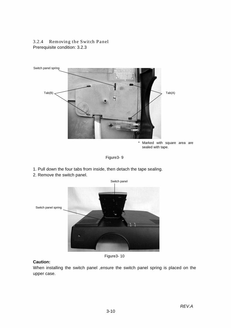
3.2.4 Removing the Switch PanelPrerequisite condition: 3.2.3
Figure3- 9
1. Pull down the four tabs from inside, then detach the tape sealing.2. Remove the switch panel.
Figure3- 10Caution:When installing the switch panel ,ensure the switch panel spring is placed on theupper case.
Tab(B) Tab(A)
* Marked with square area aresealed with tape.
Switch panel spring
Switch panel
Switch panel spring

3-11REV.A
3.2.5 Removing the Speaker Units Right / LeftPrerequisite condition: 3.2.3
Figure3- 11
(1) Speaker Unit Right
1). Remove two screws fixing the speaker unit (right) .Screw: +M3*6 F/Ni: P/N1033122 (mounting torque: 4.5kg.cm = 3.9lb.inch)
2). Disconnect the speaker cable from CN602 on the CD10MA board.
(2) Speaker Unit Left
1).Remove two screws fixing the speaker unit (left) .Screw: +M3*6 F/Ni: P/N1033122 (mounting torque: 4.5kg.cm = 3.9lb.inch)
2) Disconnect the speaker cable from CN601 on the CD10MA board.
Caution:1)The speaker unit incorporates a permanent magnet. Keep it away from
electromagnetic media such as floppy disks and magnetic cards.2) When fixing a speaker, align the two speaker holes with those of the frame, then
secure them with same tightening torque.3) Do not broken or detach the speaker cushions.
Speaker unitLeft
Speaker unitRight
screwscrew

3-12REV.A
3.2.6 Removing the CD10AU BoardPrerequisite condition: 3.2.3/3.2.9
Figure3- 12
1. Remove three screws fixing speaker bracket on the lower case, then removespeaker bracket.Screw: +M3*6 F/Ni: P/N1033122 (mounting torque: 4.5kg.cm = 3.9lb.inch)
Screw: +M3*8 F/ZN Bind : P/N1021824 (mounting torque: 4.5kg.cm = 3.9lb.inch)2. Disconnect the connector on CD10AU board.3. Remove two screws fixing CD10AU board on the speaker bracket , then remove
CD10AU board.Screw: +M3*6 F/Ni: P/N1033122 (mounting torque: 4.5kg.cm = 3.9lb.inch)
Figure3- 13
Speaker bracket
screw
screws

3-13REV.A
3.2.7 Removing the Receptor Board Assembly (FI Board / RI Board)Prerequisite condition: 3.2.3
(1) FI Board (Located on the power supply unit)
Figure3-141. Disconnect the cable connector on the FI board.2. Remove the screw fixing the FI board on the power supply unit.
Screw: +M3*6 F/Ni: P/N1033122 (mounting torque: 4.5kg.cm = 3.9lb.inch)
(2) RI Board (Located on the power supply unit)
Figure3- 15
1. Disconnect the cable connector on the RI board.2. Remove the screw fixing the RI board on the power supply unit.
Screw: +M3*6 F/Ni: P/N1033122 (mounting torque: 4.5kg.cm = 3.9lb.inch)
Caution:When installing the receptor board assembly, align the hole on the board with theboss on the frame before tightening the screw.
FI boardscrew cable connector
Receptor boardscrew
3-14REV.A
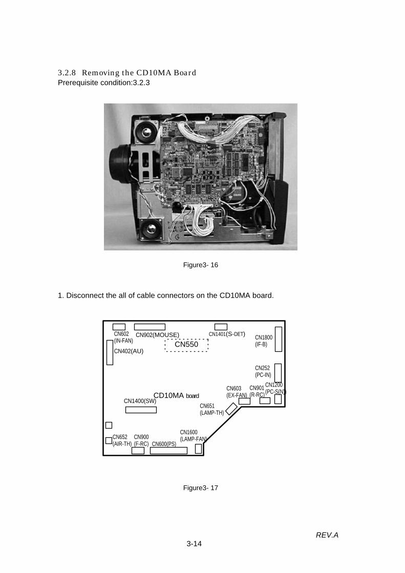
3.2.8 Removing the CD10MA BoardPrerequisite condition:3.2.3
Figure3- 16
1. Disconnect the all of cable connectors on the CD10MA board.
Figure3- 17
CN550CN602(IN-FAN)
CN902(MOUSE) CN1401(S-DET) CN1800(IF-B)
CN252(PC-IN)
CN1200(PC-S(N))CN901
(R-RC)CN603(EX-FAN)
CN651(LAMP-TH)
CN1600(LAMP-FAN)
CN600(PS)CN652(AIR-TH)
CN1400(SW)CD10MA board
CN402(AU)
CN900(F-RC)

3-15REV.A
(Continued from the previous page)
Figure3- 18
2. Remove six fixing screws on the CD10MA board.Screw: +M3*6 F/Ni: P/N1033122 (mounting torque: 4.5kg.cm = 3.9lb.inch)
3. Grasp the CD10MA board on the left side and disconnect the connector from theCD10DR board.
Caution:Never apply any mechanical stress to the CD10MA board to avoid malfunction causedby wire breaking or solder flaking.
screwscrews
screws

3-16REV.A
3.2.9 Removing the Rear Case Unit AssemblyPrerequisite conditions: 3.2.3/3.2.7
Figure3- 19
1. Remove four screws fixing the rear case on the bottom of lower case.Screw: +M3*8 F/ZN Bind : P/N1021824 (mounting torque: 4.5kg.cm = 3.9lb.inch)Screw: +M3*6 F/Ni: P/N1033122 (mounting torque: 4.5kg.cm = 3.9lb.inch)
2. Disconnect the connectors on the CD10VJ board.3. Grasp the both side of the rear case unit, then pull it out.
Caution:When installing the rear case unit assembly, slowly push it.
screws

3-17REV.A
3.2.10 Removing the CD10AJ/CD10MJ/CD10PJ/CD10VJ BoardPrerequisite condition: 3.2.3/3.2.7/3.2.8
Figure3- 20 Figure3- 21
1. Remove four screws fixing the panel, then remove the panel.Screw: +M3*6 F/Ni: P/N1033122 (mounting torque: 4.5kg.cm = 3.9lb.inch)
2. Remove two screws fixing the metal flame (upper), then remove the metal flame.3. Remove two screws fixing the metal flame (lower), then remove the metal flame. (CD10VJ board is glued on the metal flame.)
Screw: +M3*6 F/Ni: P/N1033122 (mounting torque: 4.5kg.cm = 3.9lb.inch)
Figure3- 22
(Continued on the next page)
CD10AJ board
CD10MJ boardCD10VJ board
CD10PJ board
screwsscrews
3-18REV.A
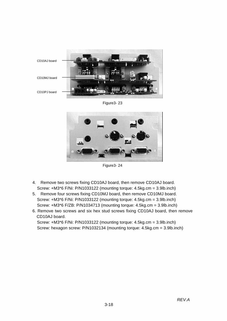
Figure3- 23
Figure3- 24
4. Remove two screws fixing CD10AJ board, then remove CD10AJ board.Screw: +M3*6 F/Ni: P/N1033122 (mounting torque: 4.5kg.cm = 3.9lb.inch)
5. Remove four screws fixing CD10MJ board, then remove CD10MJ board.Screw: +M3*6 F/Ni: P/N1033122 (mounting torque: 4.5kg.cm = 3.9lb.inch)Screw: +M3*6 F/ZB: P/N1034713 (mounting torque: 4.5kg.cm = 3.9lb.inch)
6. Remove two screws and six hex stud screws fixing CD10AJ board, then removeCD10AJ board.Screw: +M3*6 F/Ni: P/N1033122 (mounting torque: 4.5kg.cm = 3.9lb.inch)Screw: hexagon screw: P/N1032134 (mounting torque: 4.5kg.cm = 3.9lb.inch)
CD10AJ board
CD10MJ board
CD10PJ board

3-19REV.A
3.2.11. Removing the Lamp ThermistorPrerequisite condition: 3.2.3/3.2.7
Figure3- 25
1. Remove the screw fixing the lamp thermistor on the light guide unit.Screw: +M3*12 F/Zn Bind: P/N1021823 (mounting torque: 6.0kg.cm = 5.2lb.inch)
Lamp Thermister

3-20REV.A
3.2.12. Removing the Prism Duct / LV ThermistorPrerequisite condition: 3.2.3/3.2.7/3.2.8
.Figure3- 26
1. Remove the clamp screw fixing the LV thermistor cable.Screw: +M2.5*5 F/ZN: P/N1034261 (mounting torque: 4.5kg.cm = 3.9lb.inch)
2. Remove two screws fixing prism duct.Screw: +M3*8 F/ZB: P/N1033691 (mounting torque: 6.0kg.cm = 5.2lb.inch)
3. Remove the prism duct, lifting it straight up.
Caution:When you replace the prism duct, make sure that three FCC cables are not caughtbetween light guide unit and it.The filter on the prism duct is susceptible to dust and dirt. When installing the prismduct, check its cleanness and clean it if necessary.When installing the prism duct, make sure that direction is right.
Prism duct
screws
LV Thermister
Clamp screw

3-21REV.A
3.2.13. Removing the Safety SwitchPrerequisite condition:3.2.3/3.2.7/3.2.8
Figure3- 27
1. Disconnect the Fast-on tab terminals of the two cables connected to the safetyswitch.
2. Remove two fixing screws from the safety switch and detach the safety switch.Screw: +M3*12 F/Zn Bind: P-Tight P/N1021823 (mounting torque: 6.0 kg.cm = 5.2
lb.inch)
Caution:When removing the Fast-on terminals, do not apply excessive force to the terminalson the safety switch in the horizontal or vertical direction.* The polarity of the cables is not significant; connect them to any terminals on thesafety switch.
Safety switch
screws
Fast-on tab

3-22REV.A
3.2.14. Removing the Optical EnginePrerequisite condition: 3.2.3/3.2.7/3.2.8(left)
Figure3- 28
1. Remove three screws fixing speaker bracket to the optical head chassis.Screw: +M3*4 F/ZN: P/N1021795 (mounting torque: 4.0kg.cm = 3.5lb.inch)Screw: +M3*6 F/Ni: P/N1033122 (mounting torque: 4.5kg.cm = 3.9lb.inch)
2. Remove four optical block fixing screws.Screw: +M4*14 F/ZN Bind :P/N1021825 (mounting torque: 6.5kg.cm = 5.6lb.inch)
3. Pull out the speaker bracket.4. Pull the optical engine straight up from the lower case.
Figure3- 29
screws(speaker bracket)
screws

3-23REV.A
3.2.15. Removing the Power Supply Unit / PBS ThermistorPrerequisite condition: 3.2.3/3.2.7/3.2.8 (speaker R)/3.2.10
(1)Power Supply Unit
Figure3- 30
1. Remove two wire cables connecting the safety switch.2. Remove two screws (with washer) fixing the power supply cable connector, then
remove the power supply cable.Screw: +M3*10 F/Zn: P/N1038273 (mounting torque: 6.5kg.cm = 5.6lb.inch)
Power cable
screwsPower supply cable
Safety switch

3-24REV.A
PBS Thermister
Figure3- 313. Remove three screws fixing base area of the power supply unit.
Screw : M3*8 F/ZN Bind: P/N1021824 (mounting torque: 6.5kg.cm = 5.6lb.inch)4. Remove the power supply unit, lifting it straight up.
Caution:When removing the power supply unit, take care not to bend or damage the twobosses on the lower case unit. When installing the power supply unit, align the powersupply unit positioning holes with these bosses. The cooling fan and its peripheralparts in the power supply unit is susceptible to dust and dirt. When installing the powersupply unit, check fan's cleanness and clean it if necessary.
(2) PBS Thermistor
Figure3- 321). Take off the tapes fixing the PBS thermistor on the power supply unit.2). Separate the PBS Thermistor from cable clamp.
Screws
Screws are located
on the bottom of
power supply unit,
thus screws are
not shown on the
figureÅ B

3-25REV.A
3.2.16. Removing the Foot Adjuster A/BPrerequisite condition: 3.2.3
(2) Foot Adjuster B
Figure3- 33 Figure3- 34
1. Remove two screws fixing the Foot Unit on the lower case, then remove the Foot Unit.Screw: +M3*15 F/Zn Bind: P-Tight P/N1039678 (mounting torque: 6.0 kg.cm = 5.2
lb.inch)2. Remove the OP ring D on the foot adjuster.3. Push the lever, then remove the foot adjuster.
Foot adjuster OP ring screws
Lever

3-26REV.A
3.2.17. Removing the CD10DR Board AssemblyPrerequisite condition: 3.2.3/3.2.7/3.2.8
Figure3- 35EMP-7300 CD10DR board
1. Remove five hex stud screws fixing the CD10DR board.Screw: hexagon screw P/N1033069 (mounting torque: 6.0kg.cm = 5.2lb.inch)
2. Disconnect the connectors from CN 100.3. Disconnect the FPC cables from CN 700/800/900.4. Pull it straight up.
Figure3- 36 EMP-7300 CD10DR boardCaution:Before disconnecting the FPC cable from the connectors, softly pull each connectorstraight up to unlock it.
LV Thermister
CN103
CN104(Adjustment)
CN700
CN800
CD10DR board
CN900
CN100(fuse)
CN700
CN100
CN800
CN900
Hex stud screws
Hex stud screws

3-27REV.A
3.2.18. Removing the FC BoardPrerequisite condition: 3.2.1/3.2.3/3.2.7/3.2.8/3.2.14
Figure3- 37
1. Disconnect the cable connector CN1 on the FC Board.2. To detach the FC Board, remove the screw on it.
Screw: +M3*12 F/Zn Bind: P-Tight P/N1021823 (mounting torque: 6.0 kg.cm = 5.2lb.inch)
FC Board
Screw

3-28REV.A
3.2.19. Removing the Projection Lens Unit (PLU)
Caution: This paragraph is limited for references.Do not take the disassemble operations.
Prerequisite condition: 3.2.3/3.2.7/3.2.8/3.2.14
Figure3- 38 Figure3- 39
1. Remove four screws fixing the projection lens unit (PLU) and remove the projectionlens unit.(Hold the projection lens unit with your hand before removing all screws.)Screw: +M4*10 F/ZN: P/N1034026 (mounting torque: 6.0 kg.cm = 5.2 lb.inch)
Caution:1) When installing the projection lens unit, align the two bosses on the frame with the
positioning holes before tightening the screws. Tighten the screws with a torque of6.0 kg. Do not make the screws too tight (too large mounting torque may damagethe projection lens unit).
2) Take care not to touch the lens surface of the projection lens unit with a hand (toprevent their surface from being contaminated).
Screws

3-29REV.A
3.2.20. Removing the Cooling Fan / Optical Head Unit / Light GuideUnit/Exhaust fan
Caution: This paragraph is limited for references.Do not disassemble expect fans.
(You can remove the cooling fan and exhaust fan for cleaning purpose.)
Prerequisite condition: 3.2.3/3.2.7/3.2.8/3.2.14
Screws
Figure3- 40
(1) Cooling fan1. Remove two cooling fan fixing screws and remove the cooling fan.
Screw: +M4*20 F/ZN S2W1: P/N1033711 (mounting torque: 6.0kg.cm = 5.2lb.inch)
Caution:When installing the cooling fan, place it so that the label side faces down (on thealuminum die-cast side) and that its cable is oriented as shown in the photo. Clean thecooling fan until it is free of dust and dirt.

3-30REV.A
Figure3- 41
(2) Optical head unit/Light guide unit1. Remove four fixing screws in the bottom of the light guide unit.
Screw: +M4*6 F/ZN: P/N1004532 (mounting torque: 6.0kg.cm = 5.2lb.inch)
Caution:Do not touch the three light bulb screens on the optical head unit with a hand or bendthe FPC cable. When installing the light guide unit on the optical head unit, align thetwo bosses (beside the screws of front side ) to the holes of the optical head unitbefore tightening the screws.Do not disassemble or bend the light valve on the optical head unit. (Three light valvesare required factory adjustment.)
Screws
Screws

3-31REV.A
(3) Removing the Exhaust Fan Unit
Prerequisite condition: 3.2.3/3.2.7/3.2.8
Screws
Figure3- 42
Figure3- 43
1. Disconnect the cable connector CN806 on the CD10MA board.2. Remove two fixing screws on the exhaust fan.
Screw: +M4*35 F/ZB: P Tight P/N1033696 (mounting torque: 6.0kg.cm = 5.2lb.inch)3. Remove the exhaust fan.
Caution:1) When installing the exhaust fan, take care with the orientation of it. Installing the fan
in the reverse orientation may result in a device failure or extended cooling timebecause of an overheat condition. Make sure that the label on the fan facesoutward.
2) The exhaust fan unit and its peripherals are susceptible to dust and dirt. Wheninstalling the exhaust fan unit, check its cleanness and clean it if necessary.
Cable connector

Chapter 4
Troubleshooting

4-1REV.A
4.1. Before Starting Troubleshooting Procedures
1. Whenever you replace a unit or block for maintenance purposes, double-check thereplaced unit or block is defective (to determine whether the problem was due to apoor cable connection).
2. If you find questions you want to check while examining the flowchart, be sure tocheck those items during the troubleshooting procedure.
3. Refer to the instructions given in Chapter 3, "Disassembly and Assembly," whenreplacing a component unit.
4. Before making a functional check, be sure to check for proper connection.
4.1.1. Tools and Accessories Required for TroubleshootingThe tools and accessories required for troubleshooting (including fault isolation) arelisted below. They need to be prepared by the user.
Table4- 1Name Quantity Use/Remarks
Projector screen 1 To project imagesRule (3 m) 1 To measure the projection distanceHost computer 1 To supply test patterns (PC or compatible)Color display 1 To manipulate and display on host computerVideo equipment 1 To test video input
(video deck, video camera, etc.)
External speaker unit 1 To test voice output (with audio cable terminals)Multi-meter 1 To measure resistance and voltage (AC/DC)Tool set 1 set Tools and accessories listed in Section 3.1
4.1.2. Field Replacement PartsThe parts that need be replaced during troubleshooting , such as board, cases, plates,and screws, refer to the parts list listed in an appendix of this manual.
Optical engine (consist from Light guide unit, Optical head unit, Projection lens unit,Prism unit and Driver board) is the one maintenance unit. Do not separate any unitfrom optical engine.

4-2REV.A
4.2. Entry
Follow the flowchart shown below when starting troubleshooting EMP-7300 problemsand proceed to the pertinent detailed flowchart (given on the next and subsequentpates).
Figure4- 1
Outside view
Internal cable connectors
Power ON/OFF
Display/Picture quality
Audio out
Switch panel
Remote controller
Mouse/Com
interface control
Others
Start
− Visual check for outside view.
(Check out the any damage on the cover area.)
− Ensure internal cable connections on the CD10MA board .
(Remove the upper case unit.)
− Ensure power on/off and initialization (No signal display).
(Connect power cable and turn on the power.)
− Ensure screen display and picture quality.
(Connect host computer, video device and RGB monitor.)
− Ensure audio output to the internal speaker and external speaker.
− Ensure button operations on the switch panel.
− Ensure button operations on the remote controller.
− Ensure ELP communication functions from remote controller.
(ELP communication kit II option is necessary.)
− Noise, Over heat, etc.

4-3REV.A
Figure4- 2
Upper case unit
Switch panel
Rear case unit
Projection lens unit
Lower case unit
Air filter frame
Lamp cover
Lamp inner housing
Foot adjuster A/B
Interface connectors
AC inlet
Attach the air filter frame, lamp
inner housing and lamp cover.
Start
Outside view Turn off the power then remove power and interface cables.
− Any transformation or crack are not presented.
− Upper case is secured to the lower case with screws.(Refer to 3.2.3)
− Dirt condition is not presented on the receptor window (front/rear) on
the Upper case unit.
− Button switches should move in smoothly.
− Switch panel is fixed on the upper case with four tabs.
− Any transformation or crack are not presented.
− Focus ring and zoom ring are adjustable.(move it in easily)
− Dirt condition is not presented on the lens surface.
-Any transformation or crack are not presented.
− Fixing screw on the Air filter frame is not loosen.
− Tab on the Air filter frame is not transformed.
− Dirt condition is not presented on the Air filter frame.
− Dirt condition is not presented on the cooling fan.(cooling fan is located under the
Air filter frame.− Two of fixing screw on the Lamp cover are not loosen.
− Tab on the Lamp cover is not transformed.
− Any transformation or discoloration are not presented on the Lamp inner
housing frame and power cable connector.
− Any damage or dirt condition is not presented on the reflector and
circumferences.
-Foot adjuster A/B should move in smoothly.
− Any transformation or discoloration are not presented on the interface
connector. (Rust may cause discoloration.)
− Any damage or dirt condition is not presented on the Socket
− Discoloration is not presented on the connector terminal
− Any damage or dirt condition is not presented on the Socket

4-4REV.A
Preceding to the cable connection check, turn off the power then disconnect the AC powercable.Ensure the cable connection on the CD10MA board and related circuit. (Refer to the followingfigure for cable and connector location.)
Figure4- 3
Internal cable connections
Front temperature Thermister CD10AU board Cooling fan
CD10MJboard
CD10AJboard
CD10VJboard
CD10PJboard
CD10RCboard
Blowerfan
LampThermister
Exhaustfan
Powersupplyunit
CD10RCboard
LV Thermister

4-5REV.A
Figure4- 4
Disconnect all interface cable and projection lens cover then connect the power cable.
B
Does Operation and lampindicator change the condition1 to 3 which are shown next
page table.?
Does Exhaust fan work?
Refer to the table on nextpage according to the lamp
indication.
Does Exhaust fan work?
Replace CD10MA board.
Replace Exhaust fan
Press Power button on the switch panel.Operation or lamp indicator become lights
or blink.?
Make sure CN400 connectionthen replace the Switch panel.
Press Power button on the switch panel.Operation or lamp indicator become lights
or blink.?
Press Power button on the switch panel.Operation or lamp indicator become lights
or blink.?
Replace Power supply unit.
Does the lamp cover secureto lower case.?
Install the lamp cover andlamp inner housing again.
Replace the safety switch.Does the safety switchresistance is almost 0 ohm?
∗2
-Disconnect power cable.-Disconnect fast-on tab on
the safety switch.-Measure the safety switch
resistance.
A
B
Go to Start
Go to Display/
Picture quality.
∗1 : AC Measurement point
∗2 : Measure the resistance when the
safety switch is not hot condition.
YES YES
NOYES
NOYES
NO
YESYES
NO
Press Power button on theremote controller.
Operation or lamp indicatorbecome lights or blink.?
Power ON/OFF
Start
Press Power button on the
switch panel.
Operation or lamp indicatorbecome lights or blink.?
Does AC power apply to theconnector on the power
supply unit.? ∗1
NO
NOYES
YESNO
NOYES
NONO
YES
NO
YES

4-6REV.A
Figure4- 5
Continued from page 4-5
Replace power cable.
Connect AC cable to the otheroutlet.
Does AC power is applied tothe connector on the Power
supply unit.?
Does AC power is applied tothe connector on the Power
supply unit.?
Replace the power supplyunit.
NO
YES
YES
NO
A
Go to start
< Lamp indication table >Condition
Lampindicator
Operationindicator
Meanings
1 OFF Orange System initialization.2 Green-blink Green Warm up operation.3 Green Green Operating.4 Orange-blink Orange Cool down operation.5 OFF Orange Standby.
(Cool down complete)6 OFF OFF Power off condition.7 - Red or
Orange-blinkOver heat condition.
8 - Red-blink Circuit malfunction.9 Orange and Red - Lamp timer exceed 1900 hours.10 Red - Lamp life is finished.11 Red-blink - Lamp or Power supply problem.
< Suspect cause reason >
(1)Stop at the condition 1 or 8.
- CD10MAboard, Driver board(Optical engine), Power supply unit.
(2)Stop at the condition 2.
- CD10MA board, Power supply unit, Lamp inner housing.
(3)Stop at the condition 4.
-Exhaust fan, Lamp Thermister,
(4)Stop at the condition 6.(Power on problem)
-AC input, Power supply unit(include interlock switch), CD10MA board,
Safety switch.
(5)Stop at the condition 7. (Sometimes occur during operation.)
-Air filter frame(dirt condition), Exhaust fan, Power supply unit, CD10MA
board, Thermister(LV/PBS/Lamp)
(6)Stop at the condition 9 or 10.
-Lamp inner housing,, FC board.
(7)Stop at the condition 11.
-Power supply unit, Lamp inner housing.

4-7REV.A
Figure4- 6
Does “NO SIGNAL” messageappear?
Replace CD10MA board.
Does “NO SIGNAL” messageappear?
Replace Optical engine.
Does fine image appear byadjusting focus and zoom ring.
Press Menu button on theswitch panel or remote
controller.
Does Menu screen appear?
Take the adjustment shown inthe table 1.
Does fine image appear?
Replace CD10MA board.
Does fine image appear?
Take the adjustment shown inthe table 1.
Does fine image appear?
YESYES
NO NO
YES
NONO
YES
YES
NO
YES
NO
YES
NOReplace Optical engine.
Display/Picture quality
Start
Does screen appear?
Does light source lamp on?
Replace Lamp inner housing.
Does light source lamp on?
Replace CD10MA board.
Does light source lamp on?
Replace Lamp Thermister.
Does light source lamp on?
Replace Power supply unit.
Does light source lamp on?
Replace Optical engine.
YES
NOYES
NO
YES
NO
YES
NO
YES
NO
YES
NO
Go tonext page.
Table1
Computer In1/2
Video In/S-Video
− Brightness− Contrast− Synchroniz
ation− Tracking
− Brightness− Contrast− Saturation− Tint− Mode

4-8REV.A
Figure4- 7
Continued from page 4-7
Connect host computer to theComputer In 1 interface.
Does picture quality is good.?
Does screen appear.?
Change the video input by
pressing Source button.
Does screen appear.?
Replace CD10MA board.
Does screen appear.?
Replace computer cable. Press Auto button.
Does picture quality is good.?
Does picture quality is good.?
Take the adjustment shown inthe table 1(page 4-8).
Does screen appear.?
Replace Optical engine.
YES
NO
YES
YES
YES
YES
YES
NO
YES
NO
YES
NO
NO
NO
NO
NO
NONO
NO
YESYES
YES
Does following devices arechecked.?
1. Computer In 22. Video In3. S-Video
Connect the proper devicewhich are not checked.
A
AC
Connect the CRT to theMonitor interface.
Does screen appear on theCRT.?
Replace CD10MA board.
Does screen appear on theCRT.?
Replace monitor cable.
Does screen appear on theCRT.?
Replace CRT monitor.
Go to Audio out
B C
C
B

4-9REV.A
Figure4- 8
Audio output
Start
Does audio device is pluggedto the Audio interface?
Connect the audio cable tothe above interface.
Connect the audio cable tothe Audio In 1 or 2 interface.
YES
YES
YES
YES
YESYES
Does volume control works?
Replace CD10AU board.
Does internal speaker R/Loutput the sound?
Connect the external speakerto the Audio out.
Does external speaker outputthe sound?
Replace CD10AU board.
Replace CD10AU board.
Replace CD10MA board.
Does volume control works?
Replace CD10MA board.
Does Mute button works?
Does Mute button works?
Re-connect the CN402 on theCD10MA board.
Does internal speaker R/Loutput the sound?
Replace speaker R/L.
Does internal speaker R/Loutput the sound?
Replace CD10AU board.
Does internal speaker R/Loutput the sound?
Replace CD10MA board.
YES
NO
NO
NO NO
NO
NONO
YES
NO
YES
NO
YES
NO
A
A
Go to Switch panel.
Does internal speaker R/L
output the sound?
Replace CD10AJ board.

4-10REV.A
Figure4- 9
Switch panel
Start
Does Power button works?
Does Menu button works?
Does Sync +/- button works?
Does Enter button works?
Does Source button works?
Replace Switch panel.
Does all button works?
Replace CD10MA .board.
Does Blank button works?
Does Resize button works?
Does Volume button works?
Does Mute button works?
Does Tracking +/- buttonworks?
YES
NO
NO
NO
NO
YES
NO
YESYES
YES
YES
NO
NO
NO
NO
YES
NO
YES
YES
YES
NO
YES
YES
NO
Go to Remote controller.

4-11REV.A
Figure4- 10
Does Remote controllerworks with 10m distance?
Does remote controller workswith 10m distance?
Does remote controller workswith 10m distance?
Replace batteries.
Replace CD10RC board.
Replace Remote controller.
Does all switches exceptEffect1 to 5 are works
correctly?
Exchange remote controller.
Does all switches exceptEffect1 to 5 are works
correctly?
Replace CD10MA board.
Replace batteries.
Does power ON/OFF areavailable?
Exchange Remote controller.
Does power ON/OFF areavailable?
Re-connect CN900/901 onthe CD10MA board.
Does power ON/OFF areavailable?
Replace CD10RC board.
Does power ON/OFF areavailable?
Replace CD10MA board.
Does power ON/OFF areavailable?
Replace the cable betweenCD10MA toCD10RC board.
YESYES
YES
YES
YES
YES
YES
NO
NONO
NO
NO
NO
YES
NO
YES
NO
YES
NO
YES
NO
Remote controller
Start
Does power ON/OFF areavailable?
YES
NO
Go to
Mouse/
Com
control.

4-12REV.A
Figure4- 11
Mouse/Com
Start
Install the ELP link IIprogram to the host computer
again.
Does Remote controllerworks correctly?
Does Remote controllerworks correctly?
Replace CD10MJ board.
ReplaceCD10MA board.
Replace following cables.- Main cable- Mouse cable- Serial cable
Does Remote controllerworks correctly?
Does pointer button on theRemote controller works
correctly?
Does Function assignmentfor Effect button 1 to 5 are
available?
Does presentation andprojector control functionsare available with Remote
controller?
YES
YESYESYES
YES
YES
NO
NONONO
NO
NO
Go to Others.
ELP communication kit II option is necessary.
Above option is not installed, ignore the following check out flowchart

4-13REV.A
Figure4- 12
Others
Start
Noise problem? Suspect following defects.− Exhaust fan, cooling fan and inhale fan on the power supply unit.− Power supply unit (Vibration noise from pulse transformer)
Suspect following defects.− Thermister (LV/PBS/Lamp)− Exhaust fan, Cooling fan− Air filter frame (Dirt condition)
Suspect following defects.− Optical engine (May cause with dirt condition on the light guide unit, projection
lens unit and light valve on the optical head unit.)
Suspect following defects.− AC input(Include power line transit or distortion)− Power supply unit− CD10MA board− Cable connection (fail to make condition.)
Overheat problem?
Image display problem?
Low reproduced problem?
YES
YES
YES
YES
NO
NO
NO