employment of fiber laser technology to weld austenitic ... · department of mechanical ... these...
TRANSCRIPT

�������� ����� ��
Employment of fiber laser technology to weld Austenitic stainless steel 304L with Aluminum alloy 5083 using pre-placed activating flux
M.A. Ezazi, Farazila Yusof, Ahmed A.D. Sarhan, Mohd Hamdi AbdulShukor, M. Fadzil
PII: S0264-1275(15)30264-1DOI: doi: 10.1016/j.matdes.2015.08.014Reference: JMADE 422
To appear in:
Received date: 11 February 2015Revised date: 13 July 2015Accepted date: 3 August 2015
Please cite this article as: M.A. Ezazi, Farazila Yusof, Ahmed A.D. Sarhan, Mohd HamdiAbdul Shukor, M. Fadzil, Employment of fiber laser technology to weld Austenitic stain-less steel 304 L with Aluminum alloy 5083 using pre-placed activating flux, (2015), doi:10.1016/j.matdes.2015.08.014
This is a PDF file of an unedited manuscript that has been accepted for publication.As a service to our customers we are providing this early version of the manuscript.The manuscript will undergo copyediting, typesetting, and review of the resulting proofbefore it is published in its final form. Please note that during the production processerrors may be discovered which could affect the content, and all legal disclaimers thatapply to the journal pertain.
ACC
EPTE
D M
ANU
SCR
IPT
ACCEPTED MANUSCRIPT
1
Employment of fiber laser technology to weld Austenitic stainless
steel 304 L with Aluminum alloy 5083 using pre-placed activating
flux
M.A. Ezazi
1,2, Farazila Yusof
1,2,*, Ahmed A.D. Sarhan
1,2, Mohd Hamdi Abdul Shukor
1,2, M.Fadzil
2
1 Department of Mechanical engineering, University of Malaya, 50603 Kuala Lumpur, Malaysia.
2 Center of Advanced Manufacturing and Material Processing (AMMP Centre), Faculty of Engineering, University of Malaya, 50603
Kuala Lumpur, Malaysia.
Corresponding Author: Farazila Binti Yusof
Email: [email protected]
Tel: +60 3 7967 7633
Fax: +60 3 7967 5317
Abstract
The overlapping welding was carried out in keyhole mode between austenitic stainless steel 304 L
and aluminum alloy 5083 using a low power fiber laser in continuous irradiation. The significant
content of magnesium as the alloying element with low boiling point and high vapor pressure inside
the AA 5083 matrix can induce the spatter formation and depression on surface of the weld beads
upon laser beam absorption and temperature growth which can deteriorate the mechanical properties
and appearance of the joints. To reduce these defects, a variety of single and multi-components
activating fluxes including oxide-based TiO2 and halide-based CaF2 flux powders were pre-placed on
the surface of welding material prior to laser welding. The EDX and XRD analyses in addition to
microhardness and shear tests were carried out to characterize the joints. The obtained results
showed that, the oxide and halide activating fluxes can significantly improve the joints' strength up
to 1.48 and 1.85 times in average respectively compared with autogenous joint. It was deduced that
the simultaneous effect of significant decrease in joints' surface depression leading to welds'
geometry improvement in addition to less formation of interfacial Fe-Al intermetallics, were the
major causes for considerable strength improvements.
Keywords: Dissimilar materials welding, Fiber laser, Activating flux, Stainless steel 304 L,
Aluminum alloy 5083.

ACC
EPTE
D M
ANU
SCR
IPT
ACCEPTED MANUSCRIPT
2
1. Introduction
The recent anti-pollution regulations aiming to set restrictions on pollutant emissions from light road
vehicles, have forced the transportation industries to revise their manufacturing procedures in order
to meet the new policies' requirements [1]. These requirements can be met by reducing the weight of
the vehicles which can result in considerable decrease in fuel consumption and thus the air pollutants
curtailment [2,3]. Extensive efforts have been made to attain this goal through employment of
lightweight materials such as magnesium alloys, aluminum alloys and carbon-fiber-reinforced
plastics [4,5]. Amongst them, the aluminum alloys with their desirable properties including: good
stiffness and corrosion resistance have attracted exceptional attention. However their relatively
higher preparation costs and lower fatigue strength compared with other materials such as steels,
have restricted their application in structural components [4,6]. The growing need for high strength
structures having light weight and lower price in addition to increasing demand for improving the
design flexibility of products, have focused further investigations on manufacturing of light-weight
hybrid materials with remarkable mechanical properties [4]. Therefore, the welding of dissimilar
materials can be a promising method to produce the intended hybrid structures [4,5]. In particular,
the process of joining the aluminum alloys with various types of steels has undergone widespread
research due to its outstanding applicability in various structural components [7,8]. However, direct
joining of aluminum alloys to steels accompanies various challenges due to tremendous differences
in their thermo-physical properties such as coefficient of thermal expansion, specific heat and heat
conductivity which can lead to formation of various defects [9-11]. In addition, iron and aluminum
are metallurgically incompatible owing to their low solid solution miscibility, which can result in
formation of various FexAly brittle intermetallic compounds [9-11]. Various joining methods
including mechanical [2,5,12], solid state [2,4,5] and fusion joining [7,11,13], have been
implemented to join aluminum alloys to steels. Amongst them, the laser welding as a fusion joining
method has numerous advantages over the more conventional techniques due to its higher speed and
flexibility in addition to high ability to produce joints with higher depth/width ratio [14,15].
Furthermore, its more localized energy diminishes the interaction time between molten steel and
aluminum leading to a shorter thermal history, smaller heat-affected zone and less residual stress
[10,11]. Several works have been carried out to join steel to aluminum using high power lasers in the
form of continuous or pulse irradiation according to sheet thicknesses, materials type and joint
shapes many of which have investigated the laser braze welding of zinc-coated steel to aluminum
alloy [8,16]. Despite the advantages, laser braze welding of steel to aluminum alloy has shown some
difficulties namely: the low mechanical strength due to the formation of brittle reaction layer,
porosity and spatter at the seam/steel interface [6,17,18].
The deleterious effects of brittle Fe-Al intermetallics on steel-aluminum alloy joints have been
indicated by many researchers as a potential problem and profound investigations have been carried
out to control them. In a study [16], it was shown that the penetration depth of molten steel in
aluminum is a consequential factor that must be kept below 0.4 mm in order to avoid cracks and
maintain the joint's strength. In another study [12], the researchers showed that the interaction of
solid steel with molten aluminum through conduction welding can result in joints with promising
mechanical properties. Likewise, the results of another research showed that the mechanical
properties preservation can be obtained by limiting the intermetallic layer thickness below 10
[19]. Contrary, Sonia meco et al. reported that there is no optimum thickness for the intermetallics, as
the favorable effect of increasing in wetting and bonding area can compensate for the detrimental
effects of thicker intermetallics [20]. Other investigations have exhibited significant improvements in
metallurgical reactions at the joints' interfaces when a thin interlayer of copper or nickel is placed in
between the steel and aluminum sheets which can enhance the joints' toughness and tensile
properties [21-23].
It is suggested that the formation of intermetallics is dependent on the welding duration and
Rev
iewer 3
, Co
mm
ent 2

ACC
EPTE
D M
ANU
SCR
IPT
ACCEPTED MANUSCRIPT
3
temperature which can be restricted by diminishing the thermal cycle duration [4,24]. To achieve this
goal, it is suggested [25-30] that a thin deposited layer of activating flux powder on the surface of
welding material can significantly improve the low-power laser welding efficiency through
enhancing the laser-material coupling and heating more evenly throughout the thickness of materials.
This action can result in faster formation of laser-induced plasma leading to a faster peak
temperature achievement and shorter overall thermal cycle with less incidence of thermal stress.
Although the activating flux-aided welding was introduced initially through the arc welding methods
such as TIG, however the mechanism through which it improves the welding efficiency and quality
is deemed to be similar in case of laser welding [28]. There are a variety of proposed mechanisms
[25,31] that explain the higher activating flux-aided welding efficiency and quality such as:
constricting the plasma column formed between the heating source and substrate [30,32]. To explain
in detail, oxide-based activating fluxes have been reported to improve the joint's aspect ratio
(depth/width) and penetration depth via changing the Marangoni convection's direction as a result of
switching in surface tension gradient after decomposition of their structure and oxygen liberation
which acts as an active element [33,34]. Amongst the oxide activating fluxes, the TiO2 is able to
improve the absorption of laser beam through absorbing the laser radiation and transmitting its
energy to welding materials underneath the flux layer during the early period of welding [26,34]. On
the other hand, the halide-based CaF2 flux has shown promising deoxidization effects by acting as a
dilutent to existed gaseous elements such as oxygen and hydrogen in addition to high ability to
improve the absorption of heating source [26].
Nevertheless, the probable thwarting effect of activating flux on the Fe-Al intermetallics growth
through the abovementioned mechanisms for the dissimilar steel-aluminum alloy joints is unknown.
Correspondingly, the combination of advantageous properties of activating flux with a single-mode
fiber laser which has high beam quality and noticeable capabilities to produce high-aspect ratio joints
can be of high significance.
The current research is intended to investigate the effect of pre-placed oxide-based TiO2 and halide-
based CaF2 activating flux powders on the mechanical properties and metallurgical characteristics of
keyhole joints welded between stainless steel 304 L and aluminum alloy AA 5083 using a low power
fiber laser in steel-on-aluminum overlapping configuration with only one laser pass.
2. Materials and methods
2.1. Materials and sample preparation
The base materials used in this study consisted of the commercially available austenitic stainless
steel (SS) 304 L sheets with 1 mm of thickness and 3 mm thick non-heat treatable aluminum alloy
(AA) 5083 plates. The chemical composition as well as the physical and thermal properties of the
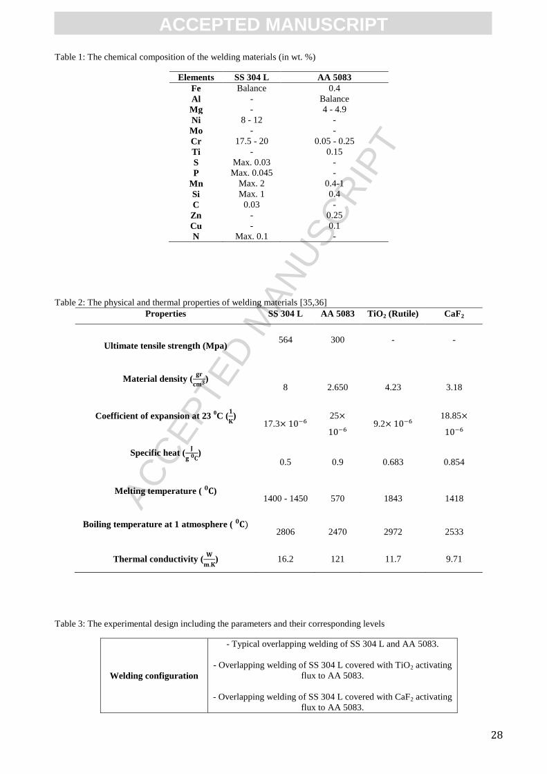
base materials are given in Table 1 and Table 2 [35,36] respectively.
Figure 1.a shows the metallographic views of etched SS 304 L illustrating a normal equiaxed
austenitic grain structure which contains the annealing twin boundaries as a result of growth accident
during the recrystallization. Besides, the microstructure of the AA 5083 in Fig. 1.b shows the
supersaturated solid solution with magnesium solute atoms that have precipitated out as an
equilibrium " " phase along the grain boundaries or have randomly distributed within the grain
structure. Using the image processing software (ImageJ® 1.47v, Wayne Rasband National Institute
of Health, USA), the average grain size for SS 304 L was estimated to be 35 , whereas it was 30
for the AA 5083. Prior to welding process, the SS 304 L and AA 5083 sheets were cut using
wire-cut EDM and then were ground using SiC grinding papers of up to 2500 grit, in order to remove
any oxide films and significant asperities which can cause gap formation via local separation. Then
the sheets were degreased thoroughly using aceton while placed in ultrasonic cleaner and eventually

ACC
EPTE
D M
ANU
SCR
IPT
ACCEPTED MANUSCRIPT
4
were cleansed using the distilled water to remove any residual surface contamination. After sample
preparation, a dial gauge was utilized for both sheets to assure that their surfaces are completely flat
before clamping, in order to avoid air-gap formation between the overlapped sheets.
Two categories of commercial flux powders were utilized in the current study. The first was the
oxide-based TiO2 (rutile) and the second was the halide type CaF2, which were provided as fine
powders to be mixed as single and double-components with ethanol as the organic carrier solvent to
form a consistent activating flux paste.
2.2. Pre-placed flux powders preparation and utilization
Figure 2 demonstrates the morphology and elemental composition of the as-received powders. In
order to remove the agglomerated particles, the flux powders were sifted using a 25 mesh size
sieve. Then each type of powder was poured separately into a low-speed planetary ball milling
equipment with zirconium oxide (ZrO2) grinding tool for 1 hour with periodic cooling breaks in
order to avoid excessive heat generation.
The deposition process of activating fluxes started with making the powder paste consistency by
mixing the flux powders with ethanol in a beaker and pouring the mixture across the surface of steel
sheets with the aid of an protruding enclosed area which retains the activating flux mixture until the
carrier solvent dries completely. In addition, ultrasonic equipment was used in order to assist
depositing the suspended particles more homogeneously throughout the steel's surface (Fig. 3).
Although the ratio of carrier solvent to flux powder is not suggested to be an critical factor [32],
however it must be within an acceptable range that forms a paste consistency with sufficient
viscosity which minimizes the immediate deposition of suspended flux powders at the bottom of
beaker. The activating flux paste was prepared by mixing 1 gr of flux powder with 10 ml of ethanol
in case of single-component setups. Correspondingly, 0.5 gr TiO2 was added to 0.5 gr of CaF2 which
were altogether mixed with 10 ml of ethanol to form the two-component activating flux paste.
Thereafter the activating flux paste was gradually poured inside the enclosed protruding area to an
extend that prevents the visual observation of steel substrate underneath the flux layer [32]. When the
carrier solvent dried completely, the "Elcometer 355" coating thickness gauge employed in 10
different points across each sample's surface, showed a thickness range of 100 + 20 for the flux
layers, which is in a good accordance with the values reported by other researchers as well [26,34].
2.3. Welding setup and methods
After materials preparation, the stainless steel sheets covered with various combinations of activating
flux powders: "TiO2", "CaF2" and "TiO2 + CaF2", were placed on the aluminum alloy sheets in
overlapping configuration under tight clamping condition (Fig. 4). Although an acceptable air gap in
between the overlapping sheets can facilitate the release of high-pressure vapors and decrease the
molten pool ejection, however the existence of such gaps can cause notch effect, keyhole's periodic
fluctuation and melt pool instability [11]. Therefore an adjustable clamping system was used to
retain the overlapped sheets in a full contact condition during the welding process. Thereafter the
laser beam was irradiated on the steel side, since the higher absorptivity of steel facilitates the laser-
induced plasma formation and it can inhibit the excessive formation of thick brittle intermetallic
compounds that usually appears in case of joints welded in aluminum-on-steel overlapping
configuration [2,16].
The keyhole welding of SS 304 L to AA 5083 was carried out under continuous irradiation by a
single-mode "Rofin starfiber 300 Ytterbium fiber laser" equipment (Fig. 4) with maximum output
power of 314 watts and 1070 nm of wavelength. The Gaussian-shaped profile of the laser beam in
this equipment has a quality (M2) equal to 1.05 and spatial intensity distribution of near perfect
(TEM00), which can be concentrated down to a minimum spot diameter of 100 in complete
focused condition when the focal distance is equal to 350 mm.

ACC
EPTE
D M
ANU
SCR
IPT
ACCEPTED MANUSCRIPT
5
Since the current research aimed at investigating the keyhole welding mode, thus all the experiments
were realized in complete focused condition while the focused laser beam was emitted on the top
surface of SS 304 L [11]. In a recent study it was reported that whenever the laser beam was focused
underneath the steel's top surface, more extensive and accentuated crazings were observed due to
increased thermal gradient at the interface of two overlapped sheets, compared with the condition in
which the laser spot was focused on the surface of steel [37]. In addition, the concentration of
optimum laser beam spot underneath the material's surface can lead to higher heat input and slower
cooling rate which provides a longer duration for the formation of intermetallic compounds that can
result in deterioration of joint's mechanical strength [1].
Prior to main experiments, extensive welding trials were carried out to identify the range of
parameters that produce weld nuggets that go all the way through the top stainless steel sheet and
reach the aluminum alloy bulk while possessing least imperfections. It was observed that whenever
the output power was set to values below 300 watts, the laser beam could hardly penetrate through
aluminum alloy bulk for even speeds of less than 5 mm/s. Therefore the design of experiment (Table
3) was performed while setting the output power to 300 watts in order to evaluate the effect of speed
on welding process considering various configurations of joining with and without activating fluxes.
2.4. Weld samples preparation for further mechanical and metallurgical analyses
In order to reveal the microstructure of the weld nuggets, the samples were cut in the direction
vertical to the weld beads' trajectory and their cross-sections were ground up to grit 2500
subsequently, followed by mirror polishing using alumina suspension. Then, the joints' cross-section
were etched using the mixture of (50 ml distilled water + 20 ml of HCl + 10 ml of H2O2) for steel
section and Keller's reagent (100 ml distilled water + 5 ml HNO3 + 3 ml HCl + 2 ml HF) for the
aluminum alloy part. The morphology, microstructure and elemental composition of the joints were
characterized using "Olympus BX61" optical microscope in addition to "Hitachi TM3030"
SEM/EDX equipment. For crystallographic characterization of fractured sections, the "Pananalytical
Empyrean" x-ray diffractometer using Cu K radiation was operated. The X-ray patterns of samples
were obtained in the step width of 0.026o and the peaks indexing was carried out using the software
configured with the XRD system. Besides, the "Instron 3369" shear strength tester equipment in
addition to "HMV microhardness tester Shimadzu" were utilized to evaluate the mechanical
properties of the joints. The microhardness tests' loading and duration were set to 2 newtons and 10
seconds respectively and the mean value of 3 pin-loaded shear strength tests (Fig. 4) per each setup
was reported based on ASTM-E8/E8M-11 [38] standard code in which the strain rate was adjusted to
0.1 mm/min. In order to investigate the joints' appearance, the "Alicona Infinite Focus" three-
dimensional scanning system was used for topographical observations and the "Mitutoyo surftest SJ-
210" tester was employed in order to examine the weld beads' top surface roughness.
3. Results and discussion 3.1. Analysis of morphological and metallurgical characteristics of joints 3.1.1. Weld beads geometry
The effect of welding speed on the appearance and cross-section of laser-welded joints are shown in
Fig. 5. For all setups, the penetration of stainless steel into the aluminum alloy's bulk increased when
the welding speed decreased. However the increasing rate in penetration depth was more remarkable
and consistent for TiO2+CaF2-aided joints compared with other welding setups whereas the joints
welded without powder showed least variation once the speed exceeded 6 mm/s (Fig. 6). This
increase in penetration happened due to the enhancement in the length of the gas capillary or in other
words the increase in linear energy of the welding [11] due to the augmentation in the output power
and/or reduction in the welding speed. Further, as the lower welding speeds led to longer laser-
material interaction, the width of the weld beads showed widening trend upon speed reduction.

ACC
EPTE
D M
ANU
SCR
IPT
ACCEPTED MANUSCRIPT
6
Similarly, the surface roughness of the beads increased upon decreasing the welding speed for all
setups.
Unlike the joints welded without activating flux (Fig. 5.a) which showed a near parallel shape on the
steel and aluminum sides of fusion zone (FZ) for various speeds, the aluminum side of the weld
nuggets in activating flux-aided joints (Fig. 5.b-d), promoted wider FZ than that on the steel side
when the laser speed decreased. As it is shown in Fig. 5.a, the depression (underfilling) is evident at
the top surface of weld beads. This lack of material was caused by enhanced vaporization-induced
recoil pressure leading to the ejection of the molten pool from the interaction zone and spatter
formation [39]. In case of our experiments, the alloying elements existed inside the solid solution
with aluminum matrix caused the molten pool ejection. To explain more, the AA 5083 is reported to
lose some portion of its alloying elements particularly the magnesium and zinc during the keyhole
laser welding due to their lower boiling temperatures (Mg ~ 1100 0C and Zn ~ 907
0C) compared
with aluminum matrix (Al ~ 2470 0C) and very high vapor pressure (1.14 5
pa for Zn and
1.11 5 pa for Mg), that can lead to significant ejection of encompassing Al-rich molten pool and
formation of cavity at weld bead's top section [40,41]. Therefore, in case another material such as
steel overlaps the AA 5083 sheet, the molten pool of the top material will be ejected as well. In this
study, the ejection of molten materials was observed whenever the laser beam penetrated completely
through the steel bulk and reached the aluminum interface to form the keyhole which left lengthwise
narrow cavities along the welding trajectory as shown in Fig. 5.a top views. The EDX analysis
performed on a typical joint welded with parameters: Power = 300 watts and V=10 mm/s, which
experienced severe magnesium loss is illustrated in Fig. 7. Likewise, the considerable amount of
magnesium detected inside the residual spatter on the weld bead's surface, validates the intervention
of high-pressure vapors of alloying elements as the main cause for materials ejection out of the
molten pool during the welding process.
Furthermore, although by decreasing the welding speed we increased the induced laser energy onto
the surface of the welding material and therefore we would expect to observe more materials melting
and evaporation, however since the lower speeds (V=4 and 5 mm/s) led to formation of relatively
bigger keyhole openings thus, the occluded gas inside the keyhole could escape the weld pool more
straightforward. Therefore the escaping gas did not eject more molten material compared with higher
speeds (V=10, 8 and 6 mm/s) in case of typical joints welded without powder (Fig. 5.a cross
sections). Moreover, the solidification cracks formed in the middle part of the weld nuggets close to
the steel-aluminum interface, were originated from the severe alterations in the molten pool's
composition as a result of significant loss of alloying elements.
On the other hand, the materials ejection is significantly less in case of joints welded with activating
fluxes compared with typical joints (Fig. 5.b-d). This observation is due to the intermediary role of
thin activating flux layer which distributed the absorbed energy more evenly throughout the whole
steel and aluminum's thickness. This action prevented the energy localization near the top section of
welding materials which is closer to the laser source leading to less vapor formation and spattering
[32]. The joints welded with CaF2 (Fig. 5.c) showed the least surface depression amongst the setups
and were almost defectless in their cross sections except for joint welded at V=4 mm/s in which a
small gas pore is visible at the lower left of weld-aluminum interface. These gas pores were more
frequently observed in case of welding with TiO2+CaF2 as it is shown in Fig. 5.d.
In general, despite the reported observations [25], we did not observe significant improvement in
penetration depth of activating flux-aided joints when the speed was set to high rate of 10 mm/s
except for joint welded with TiO2 which showed a weld nugget with deeper root penetrating through
the aluminum alloy bulk. In such a relatively higher speed, numerous horizontal and vertical cracks
were observed across the weld nugget. These cracks faded gradually upon lowering the travel speed
until the slowest rate of 4 mm/s in which a sizable vertical macro segregation was observed (Fig.
5.b).
The top surface width of the weld beads for almost all joints exhibited a growing trend upon
decreasing the welding speed with the typical joints showing the least average width of 0.89 mm

ACC
EPTE
D M
ANU
SCR
IPT
ACCEPTED MANUSCRIPT
7
followed by joints welded with TiO2+CaF2, TiO2 and CaF2 which showed average width values of
1.3, 1.34 and 1.42 mm respectively. Furthermore, the surface width of the beads for all setups
showed some transverse periodic fluctuations along the weld beads' trajectory, that might be caused
by (1) inconstant gap clearance between the steel and aluminum sheets and/or (2) the instabilities of
the keyhole. These observations are very consistent with those reported previously by G.Sierra et al.
as well in which the main cause for such instabilities was related to gas capillary-molten pool
interactions which tends to induce keyhole closure and occlusion of the gases, in addition to the
brutal variations in the pressure inside the capillary [11]. Based on the visual investigations, the
joints welded with TiO2+CaF2 demonstrated the highest weld bead consistency along the bead's
trajectory followed by CaF2, whereas the TiO2-aided welds represented lowest consistency and
highest fluctuations. Beside that, some macro-scale gas pores could be observed on top surface of the
weld beads (Fig. 5.c,d) at V=4 mm/s, whereas there were no significant hot cracks on beads'
surfaces. These pores were formed as a result of molten pool's instabilities leading to entrapment of
gaseous phases existed in the surrounding environment (such as oxygen and hydrogen) or the gases
released as a result of molten pool's elements evaporation.
The mean surface roughness (Ra) values of the weld beads showed decreasing trends when the
activating fluxes were applied so that the TiO2-aided joints possessed the least surface roughness
(smoothest bead surface) averaged 5.105 , followed by the TiO2+CaF2 and CaF2-aided joints
exhibiting 5.6302 and 6.0294 respectively.
Figure 8 illustrates the three-dimensional views of welded joints which shows the topographical
characteristics of the weld beads' surfaces at V=8 mm/s.
The formation of residual slag on the surface of the activating flux-aided joints was another
noticeable observation that has been reported by many researchers in which cases the detachability of
such slags were announced to be poor particularly for the welding with oxide-based activating fluxes
[26,30,33]. These slags (Fig. 9) were formed on the surface of the joints welded with activating
fluxes in the current study, however there were considerable differences between them in terms of
composition and detachability. Therefore in order to figure out the characteristics of these slags, we
did not remove them completely from the joints, but rather they were abraded partially by the sand
paper with grit of 1000 for 20 sec in order to reveal the actual morphology of weld beads while
keeping a small portion of the slags' residue for further analyses. In general, the slags formed by
single-component TiO2 showed the highest resistance against the abrasion compared to the other
setups whereas in case of single component CaF2, the removal process was carried out more
straightforward. In case of joints welded with TiO2, the oxygen and titanium elements were detected
almost in the same regions on the weld bead (Fig. 9.a). The negligible aluminum content detected on
the bead's surface in addition to the higher affinity of titanium to oxygen than iron oxide [25]
corroborate the TiO2 to be the main constituent of the slag, which was floated on the iron-rich molten
pool above the welding region and remained as a thin layer of slag after complete solidification of
molten pool. Correspondingly, the slags detected in case of CaF2-aided joints contained components
of calcium, iron and oxygen. The higher amount of calcium detected in the slag composition of
CaF2-aided joints compared with titanium content in TiO2-aided setup can be owing to lower density
of CaF2 compared with TiO2 (Table 2) that facilitates floating on the surface of molten pool.
Moreover, the high capability of CaF2 to dissolve the oxide species led to detection of less amount of
oxide components on the top section (Fig. 9.b). Eventually, in case of welding with TiO2+CaF2, the
slag was composed mainly of oxygen, calcium, titanium and iron.
3.1.2. Microstructure of weld-AA 5083 interface
Figure 10 shows an example for microstructure of weld-AA 5083 interface including the fusion zone
(FZ), heat-affected zone (HAZ) and AA 5083 bulk in case of welding at V=10 mm/s. The same
trends were observed at other speeds for all welding setups as well. The microstructural variations
observed in these 3 zones dominate the changes in overall behavior of the bonds due to the non-
uniform heating and solidification. The microstructure of the solidified weld pools for all setups was

ACC
EPTE
D M
ANU
SCR
IPT
ACCEPTED MANUSCRIPT
8
mainly composed of inhomogeneous and complex columnar grains resembling the dendritic
morphology as a result of rapid outward solidification of the molten pool parallel to the temperature
gradient initiating from the central regions to the weld boundaries. This directional solidification as a
result of rapid cooling rate which is typical to laser welding process, can cause hydrodynamic
movements inside the liquefied aluminum and steel mixture leading to formation of this kind of
morphology across the fusion zone [37].
The growth of these small columnar grains terminated with the appearance of narrow strip of coarser
grains in the heat-affected-zone (HAZ) with equiaxed morphology for typical setup and elongated
shape for activating flux-aided welding setups. Considering the significant dependence of HAZ
microstructure on the heating and cooling rates during the welding process, the HAZ of various
welding setups showed different width values based on their specific thermal history. The
measurement results showed that the HAZ width for the welding setups with activating flux (Fig.
10.b-d) was less than value exhibited by typical joint (Fig 10.a). This smaller HAZ for activating
flux-aided joints has the characteristic of rapid heat inducement and extraction leading to shorter
thermal history. This phenomenon is explained by the fact that when the temperature of the metal
surface raises the absorptivity to the laser radiation increases as well, which leads to transmission of
generated heat to interior parts. Therefore the faster the temperature grows, the higher amounts of
energy can be absorbed. When the steel's surface was covered with thin layer of activating flux, most
of the laser beam radiation was absorbed by the flux and transmitted to the surface of base metal
during the early period of laser action [34]. Thus, the temperature of the base metal would rise in
shorter period of time leading to a reduction in total thermal cycle duration, and the flux layer would
not exist on the steel's surface due to evaporation, forceful ejection by low-boiling point alloying
elements vapor and/or dissolving into the molten pool. This intermediate role of activating flux
medium to boost up the laser-steel coupling, led to an enhancement in absorbed energy density
although the welding power and speed were kept constant. As a result of increase in energy density,
the heat required per unit length of the weld deposit decreased as well [32]. This action contributes to
a reduction in the amount of induced heat, thereby preventing the base metal from overheating which
can in turn reduce the incidence of thermal stress, distortion and significant microstructure alteration
across the HAZ.
3.1.3. Microstructure, morphology and chemical composition of phases formed across the weld
nuggets
Figure 11 illustrates the SEM micrographs of weld nuggets' boundaries for various setups at V=10
mm/s which are given as example. Based on Fig. 11.a, the bond line of typical joint has enclosed the
welded zone with a very distinct boundary around the weld nugget circumference. However the
interfacial regions in case of welding with activating fluxes (Fig. 11.b-d), show the trace of intense
convection leading to a drastic molten materials mixture and emergence of a root-shape interface at
the weld-AA 5083 boundaries which resembles the mechanical interlock morphology. Various zones
were identified along the weld boundaries, which possessed diverse elemental compositions. The Fe-
Al intermetallic compounds (IMC) contributed to the majority of phases detected at the interfaces.
According to Fe-Al phases diagram [42], the IMC phases with FexAly stoichiometries including the
Al-rich: FeAl2, Fe2Al5, FeAl3 and the Fe-rich: Fe3Al and FeAl can be formed inevitably due to the
nature of fusion-based laser welding. The examples of EDX spectrum for Al-rich FeAl3 and Fe-rich
Fe3Al intermetallics are given in Fig. 11.a. Amongst the aforementioned intermetallic phases, the Fe-
rich compounds are recognized for their relatively higher toughness and ductility whereas the Al-rich
phases possess brittle characteristic which can deteriorate the strength of the joint as they can provide
nucleation and propagation sites for the cracks [1,2,37]. The rapid thermal cycle during the laser
welding accelerates the formation of brittle FeAl3 and Fe2Al5 with different mechanical properties
[1]. Therefore, the co-existence of these brittle IMC phases after complete solidification of weld's
molten pool may lead to physical and thermodynamic incompatibilities such as mismatches in
expansion coefficient that can ease the crack nucleation, hence the content of brittle IMC phases are

ACC
EPTE
D M
ANU
SCR
IPT
ACCEPTED MANUSCRIPT
9
in direct proportion to the existence of such cracks. The origin of the cracks (black arrows in Fig. 11)
observed across the welded regions was deduced to be the brittle Fe-Al IMC phases as well. In order
to realize the regional distribution and amount of each IMC phase across the joints welded under
various setups, the EDX area mapping along with the spot scanning were performed and the IMC
phases were determined by comparing the detected atomic percentage of aluminum and iron (Table
4) with the information provided in literature and Fe-Al phase diagram [1,2,4,43].
In general, as we scanned from the weld boundaries to the interior sections, the amount of IMC
phases richer in iron increased whereas the content of Al-rich intermetallics either decreased or
remained constant (Fig. 12). The thickness of IMC phases for various setups differed to a high extent
not only with the location within a given joint but also with the varying heat input. The thickness of
the intermetallic compounds in the middle part of the weld nuggets found out to be greater than at the
boundaries as the middle part was closer to the laser impact and therefore experienced higher
temperatures compared with the interfacial sections located at the margins of weld nuggets.
With such a large composition range (Table 4), the IMC phases at the weld nugget boundaries close
to the AA 5083 bulk in case of all welded joints were inferred to be the Al-rich: FeAl2, FeAl3 and
Fe2Al5. For all welding setups, the Fe2Al5 IMC layer possessed serrated (tongue-shaped) morphology
with jagged irregularities oriented toward the AA 5083 bulk and quasi-flat edge toward the welded
section. In case of typical joints (Fig. 11.a), the thickness of Fe2Al5 as well as the intensity of the
sharp irregularities was more significant compared with setups with activating flux, which can be
owing to exposure to an extended thermal cycle. This can be explained by considering that the
Fe2Al5 growth rate is a function of Fe-Al interaction duration as well as the immersion temperature
ranging from 973 to 1073 K during which the dissolution of "Fe" atoms in "Al" in the initial steps
leads to nucleation and propagation of this brittle phase [44]. The thickness of Fe2Al5 layer increased
for all setups when the speed decreased and in case of the typical joint welded without activating
flux, covered a range between 4 and 20 . This range exceeds the critical threshold of 10
reported by many researchers as a requirement for mechanically sound joints [12,18]. However in
case of the activating flux-aided joints, it hardly reached above this critical value for all speeds. This
observation elucidates fewer occurrences of cracks in the interfacial regions in case of the joints
welded with activating fluxes.
Moreover, it turned out that the thickness of interfacial IMC phase layers for various joints is not
consistent along the weld nuggets' boundaries. In particular, the observation of such inconsistencies
is more evident in case of Fe2Al5 intermetallic layer due to its seam-shape morphology with
distinguishable boundaries that separates the weld interiors from the AA 5083 bulk (areas showed by
"plus" symbol in Fig. 11). The main cause for such thickness fluctuations is the non-uniform thermal
cycle near the weld seam area which motivates the heterogeneous diffusion [10].
Apart from Fe2Al5, the elemental analyses led to detection of another infrequent IMC phase
resembling needle-shape platelets attached mostly to the Fe2Al5 while oriented toward the aluminum
side ("star" symbols in Fig. 11). With the aluminum content ranging 73-75 atomic percent, the
stoichiometry of this phase was found out to be FeAl3. The formation of this phase could be due to
the "Fe" re-dissolution and diffusion inside the molten pool of aluminum, possibly favored by the
convection movements of the liquid aluminum close to the intermetallic interface. Though
inconsiderable, the amount this phase was more in case of the typical joint welded without powder
than the activating-flux aided joints. This is owing to the more heat input induced inside the typical
joint leading to longer thermal history and slower cooling rate, as it is suggested that the formation of
FeAl3 is determined by the cooling rate which is a function of heat input. Therefore, the large heat
input can cause slower cooling down rate resulting in more formation of FeAl3 precipitates [45].
Unlike the Fe2Al5 and FeAl3 brittle phases that were detected in small quantities at weld boundaries,
the Fe-rich phases were detected more frequently inside the weld nuggets for all setups. According to
a study [46], unlike the more diffusion controlled Fe2Al5 and FeAl3, the IMC phases richer in "Fe"
particularly the FeAl and Fe3Al are preferentially formed at higher temperatures of over 1273 K.

ACC
EPTE
D M
ANU
SCR
IPT
ACCEPTED MANUSCRIPT
10
That is why the content of these phases was considerable at middle section of weld nuggets as the
central regions were in direct exposure to the laser beam radiation.
Considering the EDX analyses, SEM micrographs and microhardness experiments performed across
various regions of the weld nuggets, the Fe-Al intermetallic compounds percentage (IMCP) [2]
calculated using the following equation can be plotted with respect to various welding setups and
speeds (Fig. 13):
IMCP = (
(1)
where "IMCP" is the intermetallic compounds percentage, "A1" is the area of intermetallic phases
and "A2" is the total area of the weld nugget in cross section view.
As shown in Fig. 13, the Al-rich brittle phases including Fe2Al5 and FeAl3 constituted the least
contents of IMC phases for all setups, whereas the Fe-rich ductile phases were detected in
significantly higher percentages. Besides, as the speed decreased the amount of Al-rich Fe2Al5 and
FeAl3 phases increased for all setups. This can be due to more upward movement of molten
aluminum toward the steel section as a result of increase in convection forces inside the molten pool
which led to more dilution of steel and more Fe-Al reactions [2]. Further, the FeAl2 content showed
almost a constant trend for all speeds whereas the Fe-rich FeAl represented an increasing trend as the
speed decreased, although its variation was not considerable. In case of Fe3Al phase, the variation of
speed led to variable amounts without showing a specific trend, although in case of TiO2+CaF2 and
CaF2 the amount of Fe3Al increased when the speed decreased. To conclude, the joints welded
without activating flux, showed the highest percentage of IMC phases in average for various speeds,
followed by welding setups with TiO2 and TiO2+CaF2 whereas the CaF2-aided joints showing the
least contents of IMC phases.
Apart from the Fe-Al intermetallics, the EDX area mapping at cross section of the joints (results at
V=10 mm/s are shown in Fig. 14) showed the detection of oxide components as well. In case of all
setups, as the welding speed decreased the amount of oxygen detected inside the molten pool
increased. From the Fig. 14.b, it is evident that the oxygen content in case of the joints welded with
TiO2 is significantly more compared with typical setup (Fig. 14.a) and other activating flux-aided
joints (Fig. 14.c,d) whereas the welding setup with CaF2 showed the least amount of oxide
impurities. It is noteworthy to say that the detected oxygen in case of TiO2-aided joints can be
originated from the dissolution of liberated oxygen inside the molten pool as a result of TiO2
decomposition under very high temperature of laser source, although the decomposition of TiO2 is
difficult due to its structural stability even at very high temperatures [32,33].
As it is illustrated in Fig. 14.b-d, the elemental analyses led to detection of flux powders' components
melted down inside the molten pool of the joints. More amounts of flux components were detected
above the steel-aluminum alloy interface compared with bottom sections. Beside that, when the
welding speed decreased, the content of flux components existed inside the molten pool decreased
significantly which is an attribute of more flux powder evaporation due to exposure to longer laser
beam irradiation. In case of welding with TiO2 (Fig. 14.b), more amount of flux particles was
detected which can be owing to higher melting and evaporation temperature of rutile TiO2 compared
with CaF2.
The small portion of flux powders melted down inside the molten pool of the joints welded with
activating fluxes, might contribute to more enhancement in penetration depth and surface compared
with typical joints as shown in Fig. 5 and 6. It is suggested that the flux powders dissolved into the
weld pool can act as an interference to the heat transfer inside the hot molten pool due to their
significantly lower thermal conductivity values compared with base metals [29]. In fact, the
mechanism of heat transfer in metals is through the flow of free electrons. The extremely hot molten

ACC
EPTE
D M
ANU
SCR
IPT
ACCEPTED MANUSCRIPT
11
pool during the welding is full of thermally induced electrons. If the transfer of the hot electrons
happens rapidly the heat existed in the molten pool would be less, therefore leading to a reduction in
the penetration depth. As a matter of fact, the thermal conductivity of both TiO2 and CaF2 powders
(Table 2) is significantly less than that of the AA 5083 and SS 304 L. Hence, the dissolution of these
powders in the molten pool reduced the heat transfer and subsequently enhanced the penetration
depth.
3.2. Mechanical properties of the joints 3.2.1. Microhardness characterization of weld nuggets
In order to correlate the elemental analyses and microscopic observations to mechanical properties,
the transverse microhardness indentations (Vickers) were carried out along the top and bottom of the
joints' cross section and the measurement results at V=10 mm/s is presented as example in Fig. 15.
The indentations were performed with offset distance of 300 above and below the steel-
aluminum alloy interface. For all welding setups, the results showed remarkable increase in mean
hardness values across the joints and slight hardness loss across the heat affected zones adjacent to
steel sections considering that the hardness values for AA 5083 and SS 304 L original materials were
measured 74 and 210 respectively. The higher hardness across the joint areas is due to the very
fast cooling rate during the laser welding favoring the formation of fine dendritic microstructure
within the fusion zone (Fig. 10) which usually imparts augmented hardness values [47].
Correspondingly, the sharp increase in hardness values within the joints is owing to the formation of
various Fe-Al intermetallic phases which are significantly harder than either SS 304 L or AA 5083
bulks [2,11,46].
Despite the extremely limited thermal cycle in laser welding process which can restrict the molten
steel-aluminum interaction, the aluminum components were detected in upper section of the joints in
case of welding with activating fluxes (Fig. 14.b-d). This up flow movement of liquefied aluminum
into the steel's molten pool as a result of convection forces, was the main cause of IMC-induced
hardness increase at upper section of activating flux-aided joints, however the elemental analysis of
the typical joint welded without flux (Fig. 14.a) showed rather negligible amount of aluminum at
upper weld section. This observation invalidates the influence of IMC phases in hardness increase
for this setup. Based on the results reported in literature [47,48], the extended exposure to high
temperatures during welding process can make the steels containing large amount of chromium such
as SS 304 L, more prone to sensitization process in which the chromium tends to bond with carbon
content to form the chromium carbide precipitate (CCP) on the grain boundaries. This precipitate can
impede the movement of dislocations and therefore cause the reduction of ductility. Hence, the
observation of wider heat-affected zones adjacent to the aluminum section shown in Fig. 10.a in
addition to significant hardness loss across the HAZ adjacent to steel bulk (Fig. 15.a) consolidate the
exposure to longer thermal history as the influential factor to ease the CCP transition inside the
steel's molten pool for typical joints.
On the other hand, the transition from both the joint and bulk material areas into the HAZ adjacent to
steel sections accompanied slight hardness reduction for all setups. This reduction can be due to the
slight increase in mean size of austenite and ferrite grains due to tempering effect of steel above 600 0C [49]. The degree of hardness reduction in addition to the proliferation extent into the bulk
materials was perceived to be a function of welded joints' thermal history as discussed earlier. The
typical joints (Fig. 15.a) showed wider HAZ adjacent to steel section compared with the joints
welded with activating fluxes, which is due to the longer thermal cycle leading to slower heat
extraction during the cooling down process. In addition, the joints welded with TiO2 and TiO2+CaF2
(Fig. 15.b,d) possessed almost the same HAZ size, whereas the CaF2-aided joints showed the least
extended HAZ adjacent to steel bulk (Fig. 15.c). Correspondingly, the joints welded with TiO2+CaF2
represented exceptional hardness preservation by showing the average hardness of 203.6 in the
HAZ, followed by CaF2 and TiO2 showing 196.8 and 194.7 respectively, whereas the typical
joints welded without activating flux demonstrated the least average hardness value of 193.2

ACC
EPTE
D M
ANU
SCR
IPT
ACCEPTED MANUSCRIPT
12
which is equal to 8% of hardness loss in HAZ adjacent to steel bulk. On the other hand, no
significant hardness alteration could be observed on the HAZ of the joints adjacent to AA 5083 bulk.
Fig. 16 shows the variation of hardness values across the fusion and heat-affected zones adjacent to
both the steel and aluminum bulks for different setups with respect to various welding speeds.
Overall, as the welding speed decreased the mean hardness values across the joints increased which
is due to the increase in aluminum percentage inside the weld caused by higher penetration depth that
contributes to formation of brittle Al-rich IMC phases. Contrary, the speed reduction made the mean
hardness values on HAZ adjacent to both SS 304 L and AA 5083 to show slight decreasing trend.
The HAZ beside the AA 5083 section showed insignificant decreasing trend for almost all setups
when speed decreased, however it was more significant in case of typical welding setup without
activating flux. Despite that, reducing the speed led to more significant reduction in mean hardness
across the HAZ adjacent to SS 304 L sections for all setups, so that the typical and TiO2-aided joints
showed 22 and 20 units of hardness loss compared with SS 304 L bulk in case of welding at V=4
mm/s.
3.2.2. Shear strength
The results of shear strength tests in case of joints welded under various welding setups are given
with respect to various speeds in Fig. 17. The error bars in the diagram designate the shear force
values scatter within 3 specimens corresponding to each welding speed. Considering various welding
speeds, the joints welded with CaF2 showed the highest strength (average: 5.225 kN) followed by
joints welded with TiO2+CaF2 (average: 4.355 kN) and TiO2 (average: 4.163 kN) whereas the joints
welded under the typical setup demonstrated the least strength (average: 2.812 kN). The superiority
of maximum shear strength values (CaF2: 5.656 kN ~ 452 N/mm and TiO2+CaF2: 4.888 kN ~ 391
N/mm) obtained in the current study is evident when compared with the maximum shear strength
results achieved in the most similar previous works: 250 N/mm [11], around 4.7 kN [1], 158 N/mm
[43] and 250 N/mm [10]. From the viewpoint of joints' geometry, the higher strength represented by
joints welded with activating fluxes can be essentially ascribed to the less surface depression at
joints' surfaces which reduced the shear stress concentration. In addition, the root-shape morphology
of weld nuggets interface with AA 5083 at the bottom section contributed to strength enhancement
through acting similar to the mechanical interlocking mechanism. However, considering the joints'
metallurgy the simultaneous effect of two factors influenced the joints strength which are: 1)
penetration depth of joints and effective wetting area between molten steel and aluminum and 2)
percentage of brittle Fe-Al intermetallic phases. Although many authors have attributed the fracture
of dissimilar steel-aluminum alloy joints mostly to IMC phases thickness, however the shear strength
tests' results indicate that mechanical strength of joints can not be directly correlated to IMC
thickness. From Fig. 17, it is evident that although the speed reduction can expose molten pool to
longer thermal history and accelerate the formation of thick brittle IMC phases, however the highest
shear strength values were not achieved at higher speeds in which the IMC formation is less, but
rather at intermediate speeds. To explain in detail, when the welding parameters induce the formation
of thicker IMC phases particularly at higher powers or lower speeds, the wetting area of the
aluminum and iron increases as well which can result in stronger joints. Owing to these concomitant
facts, the potential detrimental effects of increasing in brittle IMC thickness upon speed reduction
can be compromised by the compensating effect of increasing in the wetting area between the mixed
materials [6,20]. This increase in wetting area between molten pools of aluminum and iron is
apparent from the wider and deeper nuggets obtained with activating fluxes particularly at lower
speeds (Fig. 5). Moreover, Fig. 17 indicates that when the welding speed set to highest value (V=10
mm/s), the lack of sufficient penetration into the aluminum bulk and smaller wetting area between
two materials, did not result in promising strength values. Correspondingly, when the speed set to
lowest value (V=4 mm/s), the excessive formation of brittle IMC phases restricted the gain for
higher strength values.

ACC
EPTE
D M
ANU
SCR
IPT
ACCEPTED MANUSCRIPT
13
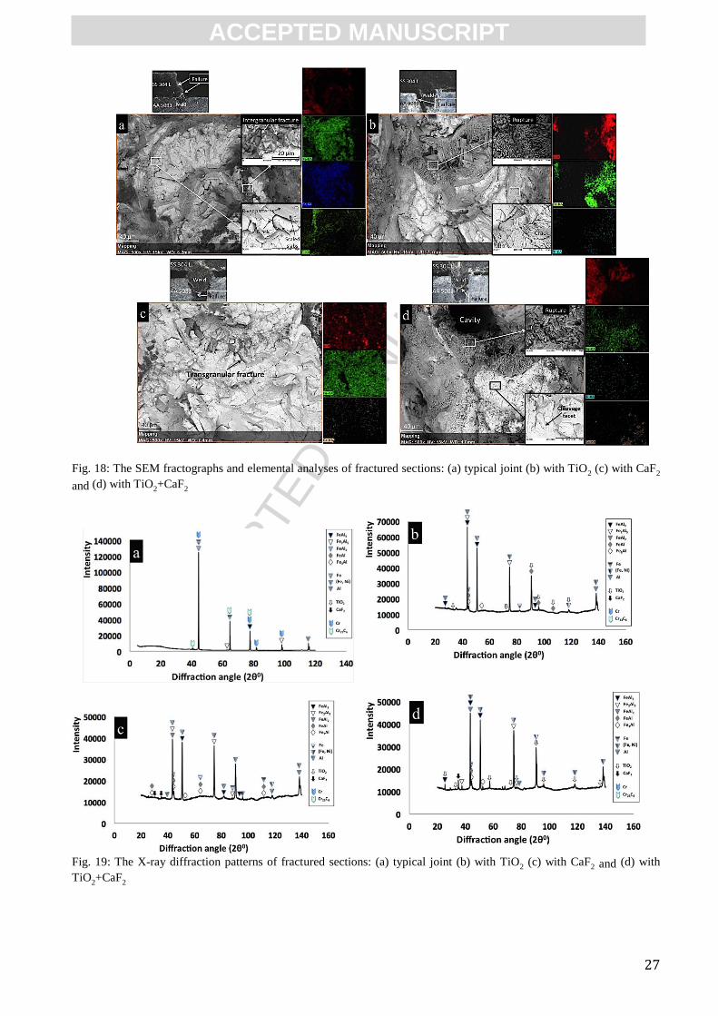
3.2.3. Fractographic and elemental analyses of fractured sections
The failure locations after shear strength tests in addition to the normal (500x) and magnified
(4000x) fractographs of fractured sections in case of the samples with highest strength (typical weld
at V=6, TiO2 at V=8, CaF2 at V=6 and TiO2+CaF2 at V=6 mm/s) are illustrated in Fig. 18. The
samples failure occurred at aluminum alloy-weld interfaces along the Fe-Al intermetallics in case of
the joints welded with activating fluxes, and at steel-weld interface in case of typical joint which
exhibited the characteristics of brittle fracture predominantly. The high thickness of AA 5083 sheets
(3 mm) in addition to high shear strength of SS 304 L bulk even at the HAZ are the main reasons for
fracture being located at weld interfaces.
As it is shown in Fig. 18.a, the significant molten pool's ejection that led to considerable surface
depression at joint's top section localized the shear force at this weaker point which resulted in
failure at steel-weld interface. The fractured section of the failed typical joint at the weld side
exhibits the propagated cracks and shiny scaled slabs with sharp edges and river patterns which
characterizes the brittle fracture. In addition, the occurrence of intergranular fracture is evident as a
result of chromium carbide precipitation at the grain boundaries.
From the Fig. 18.b, a ruptured zone with blunt edges and a large cavity can be observed at the weld
side of the fractured section which characterizes the overloading condition. Beside that, the SEM
image at higher magnification reveals the trace of crack propagation during the shear force
application which led to brittle fracture. Similarly, the fractograph of the TiO2+CaF2 failed joint on
the weld side (Fig. 18.d), characterizes similar morphology to TiO2 fracture section by showing the
ruptured areas in addition to cleavage zones with conchoidal morphology. However the failure of the
CaF2 joint (Fig. 18.c) shows merely the transgranular cleavage planes which are the characteristics of
brittle fracture as well.
Furthermore, the EDX area mapping (Fig. 18) carried out at the fractured sections of failed activating
flux-aided joints, detected the components of flux powders melted down inside the molten pool
which corroborates the reported results in section 3.1.3. Nevertheless, no evidence was found to
validate the deleterious effect of melted down flux components on joints' shear strength.
3.2.4. Crystallographic analyses of fractured sections
In order to identify the phases in charge of joints' failure, the XRD analyses were performed on the
weld side of fractured sections (Fig. 19). In conformity with EDX analyses (Fig. 18), the majority of
phases detected at failure zones of the joints welded with activating fluxes are composed of Fe-Al
intermetallics (Fig. 19.b-d). The intensity of brittle intermetallics particularly the FeAl3 and Fe2Al5
was higher in case of welding setup with TiO2 (Fig. 19.b) compared with the joints welded with CaF2
and TiO2+CaF2. This observation justifies the lower shear strength of TiO2-aided joints compared
with other joints welded with activating fluxes (Fig. 17). Moreover, the inconsiderable peaks of CaF2
and TiO2 validated further the dissolution of small portion of flux powders inside the molten pool
during the welding process which are in accordance with the EDX results reported in last sections
(Fig. 14 and 18).
On the other hand, the significant amount of chromium and chromium carbide phases which were
detected in case of typical joint (Fig. 19.a), consolidates the deleterious effect of sensitization process
on shear strength of typical joint. In addition, the slight intersection of typical joint's fractured section
with upper part of the weld nugget, led to detection of brittle Fe-Al intermetallics with insignificant
intensities.

ACC
EPTE
D M
ANU
SCR
IPT
ACCEPTED MANUSCRIPT
14
Conclusion
A novel technique was proposed to perform keyhole welding between austenitic stainless steel 304 L
(low carbon) and aluminum alloy 5083 with the aid of oxide-based TiO2 and halide-based CaF2
activating fluxes. Based on the obtained results and analyses, the following conclusions can be
declared:
1) Sound overlapping joints with narrow heat-affected zones can be achieved by a low power
continuous wave fiber laser and only one pass after application of activating flux powders.
2) The molten pool's ejection caused by high pressure vapors of alloying elements led to significant
depression (underfilling) on top section of typical joints. The surface depressions decreased
significantly after application of activating fluxes, owing to the intermediate role of thin activating
flux layer which distributed the absorbed laser energy with higher density throughout the whole
thickness of both steel and aluminum alloy sheets. This action decreased the localization of laser
energy on top section of welding materials which is closer to the laser impact. Furthermore, the
considerable reduction in joints' surface depression can be owing to direction reversal in Marangoni
convection within the molten pool which turned the surface tension's pulling force into the inward
pushing force leading to better molten pool integrity on the keyhole's opening and hence the higher
resistance against the escaping gaseous phases.
3) The thin layer of activating flux powders absorbed the laser energy and transmitted it to the bulk
material during the early period of laser action which led to an immediate laser-material coupling,
faster heat inducement and extraction resulting in shorter overall thermal cycle. This action restricted
the formation of Fe-Al brittle intermetallic phases and contributed to weld-AA 5083 and weld-SS
304 L interfaces with extremely small heat-affected zones.
4) The shear strength values can reach as high as 5.656, 4.888 and 4.735 kN in case of joints welded
with CaF2, TiO2+CaF2 and TiO2 respectively which show considerable improvements compared with
typical joints. It was deduced that these significant improvement were achieved due to the
simultaneous effect of significant decrease in surface depression which prevented the shear force
from concentration in addition to less formation of brittle interfacial Fe-Al intermetallics.
Acknowledgement
The authors would like to acknowledge the University of Malaya for providing the necessary
facilities and resources for this research. This research was fully funded by the Ministry of Higher
Education, Malaysia with the high impact research (HIR) grant number of HIR-MOHE-16001-
D000001.
References
[1] H.-C. Chen, A. J. Pinkerton, L. Li, Z. Liu, and A. T. Mistry, “Gap-free fibre laser welding of
Zn-coated steel on Al alloy for light-weight automotive applications,” Mater. Des., vol. 32,
no. 2, pp. 495–504, 2011.
[2] M. J. Torkamany, S. Tahamtan, and J. Sabbaghzadeh, “Dissimilar welding of carbon steel to
5754 aluminum alloy by Nd:YAG pulsed laser,” Mater. Des., vol. 31, no. 1, pp. 458–465, Jan.
2010.
[3] S. Chen, L. Li, Y. Chen, and J. Huang, “Joining mechanism of Ti/Al dissimilar alloys during
laser welding-brazing process,” J. Alloys Compd., vol. 509, no. 3, pp. 891–898, Jan. 2011.
[4] E. Taban, J. E. Gould, and J. C. Lippold, “Dissimilar friction welding of 6061-T6 aluminum
and AISI 1018 steel: Properties and microstructural characterization,” Mater. Des., vol. 31,
no. 5, pp. 2305–2311, May 2010.
Rev
iewer 3
, Co
mm
ent 2

ACC
EPTE
D M
ANU
SCR
IPT
ACCEPTED MANUSCRIPT
15
[5] T. Sakayama, Y. Naito, Y. Miyazakki, T. Nose, G. Murayma, K. Saita, and H. Oikawa,
“Dissimilar metal joining technologies for steel sheet and aluminum alloy sheet in auto body,”
Nippon Steel Tech. Rep, vol. 103, pp. 91–98, 2013.
[6] A. Mathieu, R. Shabadi, A. Deschamps, M. Suery, S. Matteï, D. Grevey, and E. Cicala,
“Dissimilar material joining using laser (aluminum to steel using zinc-based filler wire),” Opt.
Laser Technol., vol. 39, no. 3, pp. 652–661, Apr. 2007.
[7] H. Zhang and J. Liu, “Microstructure characteristics and mechanical property of aluminum
alloy/stainless steel lap joints fabricated by MIG welding–brazing process,” Mater. Sci. Eng.
A, vol. 528, no. 19–20, pp. 6179–6185, Jul. 2011.
[8] L. H. Shah and M. Ishak, “Review of Research Progress on Aluminum–Steel Dissimilar
Welding,” Mater. Manuf. Process., vol. 29, no. 8, pp. 928–933, 2014.
[9] S. Yan, Z. Hong, T. Watanabe, and T. Jingguo, “CW/PW dual-beam YAG laser welding of
steel/aluminum alloy sheets,” Opt. Lasers Eng., vol. 48, no. 7–8, pp. 732–736, Jul. 2010.
[10] C. Dharmendra, K. P. Rao, J. Wilden, and S. Reich, “Study on laser welding–brazing of zinc
coated steel to aluminum alloy with a zinc based filler,” Mater. Sci. Eng. A, vol. 528, no. 3,
pp. 1497–1503, Jan. 2011.
[11] G. Sierra, P. Peyre, F. Deschaux-Beaume, D. Stuart, and G. Fras, “Steel to aluminium key-
hole laser welding,” Mater. Sci. Eng. A, vol. 447, no. 1–2, pp. 197–208, Feb. 2007.
[12] G. Sierra, P. Peyre, F. Deschaux Beaume, D. Stuart, and G. Fras, “Galvanised steel to
aluminium joining by laser and GTAW processes,” Mater. Charact., vol. 59, no. 12, pp.
1705–1715, Dec. 2008.
[13] M. M. Atabaki, M. Nikodinovski, P. Chenier, J. Ma, M. Harooni, and R. Kovacevic, “Welding
of aluminum alloys to steels: an overview,” J Manuf Sci Prod, vol. 14, no. 2, pp. 59–78, 2014.
[14] J. P. Bergmann, M. Bielenin, M. Stambke, T. Feustel, P. V. Witzendorff, and J. Hermsdorf,
“Effects of Diode Laser Superposition on Pulsed Laser Welding of Aluminum,” Phys.
Procedia, vol. 41, pp. 180–189, Jan. 2013.
[15] J. Um and I. a. Stroud, “Total Energy Estimation Model for Remote Laser Welding Process,”
Procedia CIRP, vol. 7, pp. 658–663, Jan. 2013.
[16] S. Katayama, “Laser welding of aluminium alloys and dissimilar metals,” Weld. Int., vol. 18,
no. 8, pp. 618–625, Aug. 2004.
[17] A. Mathieu, S. Pontevicci, J. Viala, E. Cicala, S. Matteï, and D. Grevey, “Laser brazing of a
steel/aluminium assembly with hot filler wire (88% Al, 12% Si),” Mater. Sci. Eng. A, vol.
435–436, pp. 19–28, Nov. 2006.
[18] H. T. Zhang, J. C. Feng, P. He, and H. Hackl, “Interfacial microstructure and mechanical
properties of aluminium–zinc-coated steel joints made by a modified metal inert gas welding–
brazing process,” Mater. Charact., vol. 58, no. 7, pp. 588–592, Jul. 2007.
[19] M. J. Zhang, G. Y. Chen, Y. Zhang, and K. R. Wu, “Research on microstructure and
mechanical properties of laser keyhole welding–brazing of automotive galvanized steel to
aluminum alloy,” Mater. Des., vol. 45, pp. 24–30, Mar. 2013.
[20] S. Meco, S. Ganguly, S. Williams, and N. McPherson, “Effect of Laser Processing Parameters
on the Formation of Intermetallic Compounds in Fe-Al Dissimilar Welding,” J. Mater. Eng.
Perform., vol. 23, no. 9, pp. 3361–3370, Jun. 2014.
[21] S. Chen, J. Huang, K. Ma, H. Zhang, and X. Zhao, “Influence of a Ni-foil interlayer on Fe / Al
dissimilar joint by laser penetration welding,” Mater. Lett., vol. 79, pp. 296–299, 2012.
[22] S. Chen, J. Huang, K. Ma, X. Zhao, and A. Vivek, “Microstructures and Mechanical
Properties of Laser Penetration Welding Joint With/Without Ni-Foil in an Overlap Steel-on-
Aluminum Configuration,” Metall. Mater. Trans. A, vol. 45, no. 7, pp. 3064–3073, Mar. 2014.
[23] S. Chen, Z. Zhai, J. Huang, X. Zhao, and J. Xiong, “Interface microstructure and fracture
behavior of single/dual-beam laser welded steel-Al dissimilar joint produced with copper
interlayer,” Int. J. Adv. Manuf. Technol., Jun. 2015.
ACC
EPTE
D M
ANU
SCR
IPT
ACCEPTED MANUSCRIPT
16
[24] R. Borrisutthekul, T. Yachi, Y. Miyashita, and Y. Mutoh, “Suppression of intermetallic
reaction layer formation by controlling heat flow in dissimilar joining of steel and aluminum
alloy,” Mater. Sci. Eng. A, vol. 467, no. 1–2, pp. 108–113, Oct. 2007.
[25] M. Kuo, Z. Sun, and D. Pan, “Laser welding with activating flux,” Sci. Technol. Weld. Join.,
vol. 6, no. 1, pp. 17–22, 2001.
[26] G. Qin, G. Wang, and Z. Zou, “Effects of activating flux on CO2 laser welding process of
6013 Al alloy,” Trans. Nonferrous Met. Soc. China, vol. 22, no. 1, pp. 23–29, Jan. 2012.
[27] S. G. Parshin, S. S. Parshin, and G. Buerkner, “The effect of ultrafine particles of activating
fluxes on the laser welding process,” Weld. Int., vol. 26, no. 12, pp. 980–983, 2012.
[28] A. Klimpel, A. Lisiecki, and M. Szczyrba, “Diode-laser welding of duplex steels using an
activating flux,” Weld. Int., vol. 17, no. 9, pp. 684–692, 2003.
[29] M. Aghakhani, M. R. Ghaderi, a. Karami, and a. a. Derakhshan, “Combined effect of TiO2
nanoparticles and input welding parameters on the weld bead penetration in submerged arc
welding process using fuzzy logic,” Int. J. Adv. Manuf. Technol., vol. 70, no. 1–4, pp. 63–72,
Aug. 2013.
[30] T.-S. Chern, K.-H. Tseng, and H.-L. Tsai, “Study of the characteristics of duplex stainless
steel activated tungsten inert gas welds,” Mater. Des., vol. 32, no. 1, pp. 255–263, 2011.
[31] K.-H. Tseng and K.-L. Chen, “Comparisons Between TiO<SUB>2</SUB>- and
SiO<SUB>2</SUB>-Flux Assisted TIG Welding Processes,” J. Nanosci. Nanotechnol., vol.
12, no. 8, pp. 6359–6367, Aug. 2012.
[32] K.-H. Tseng, “Development and application of oxide-based flux powder for tungsten inert gas
welding of austenitic stainless steels,” Powder Technol., vol. 233, pp. 72–79, Jan. 2013.
[33] S. Lu, H. Fujii, H. Sugiyama, M. Tanaka, and K. Nogi, “Weld penetration and Marangoni
convection with oxide fluxes in GTA welding,” Mater. Trans., vol. 43, no. 11, pp. 2926–2931,
2002.
[34] H. Sun, G. Song, and L. F. Zhang, “Effects of oxide activating flux on laser welding of
magnesium alloy,” Sci. Technol. Weld. Join., vol. 13, no. 4, pp. 305–311, May 2008.
[35] C. B. Carter and G. Norton, Ceramic Materials: Science and Engineering. Springer, pp. 90–
150, 2013.
[36] W. F. Gale and T. C. Totemeier, Smithells Metals Reference Book. Elsevier Science, pp.
1910–1985, 2003.
[37] A. Kouadri-David, “Study of metallurgic and mechanical properties of laser welded
heterogeneous joints between DP600 galvanised steel and aluminium 6082,” Mater. Des., vol.
54, pp. 184–195, 2014.
[38] “ASTM E8 / E8M-11, Standard Test Methods for Tension Testing of Metallic Materials,
ASTM International, West Conshohocken, PA, www.astm.org.”, 2011.
[39] M. J. Zhang, G. Y. Chen, Y. Zhou, S. C. Li, and H. Deng, “Observation of spatter formation
mechanisms in high-power fiber laser welding of thick plate,” Appl. Surf. Sci., vol. 280, pp.
868–875, Sep. 2013.
[40] J. M. Sánchez-Amaya, T. Delgado, L. González-Rovira, and F. J. Botana, “Laser welding of
aluminium alloys 5083 and 6082 under conduction regime,” Appl. Surf. Sci., vol. 255, no. 23,
pp. 9512–9521, Sep. 2009.
[41] Y. Zhang, J. R. G. Evans, and S. Yang, “Corrected Values for Boiling Points and Enthalpies
of Vaporization of Elements in Handbooks,” J. Chem. Eng. Data, vol. 56, no. 2, pp. 328–337,
Jan. 2011.
[42] O. Kubaschewski, IRON—Binary Phase Diagrams. Springer Berlin Heidelberg, pp. 5–12,
2013.
[43] J. Ma, M. Harooni, B. Carlson, and R. Kovacevic, “Dissimilar joining of galvanized high-
strength steel to aluminum alloy in a zero-gap lap joint configuration by two-pass laser
welding,” Mater. Des., vol. 58, pp. 390–401, Jun. 2014.
ACC
EPTE
D M
ANU
SCR
IPT
ACCEPTED MANUSCRIPT
17
[44] S. Kobayashi and T. Yakou, “Control of intermetallic compound layers at interface between
steel and aluminum by diffusion-treatment,” Mater. Sci. Eng. A, vol. 338, no. 1–2, pp. 44–53,
Dec. 2002.
[45] L. Shao, Y. Shi, J. K. Huang, and S. J. Wu, “Effect of joining parameters on microstructure of
dissimilar metal joints between aluminum and galvanized steel,” Mater. Des., vol. 66, pp.
453–458, Feb. 2015.
[46] X. Liu, S. Lan, and J. Ni, “Analysis of process parameters effects on friction stir welding of
dissimilar aluminum alloy to advanced high strength steel,” Mater. Des., vol. 59, pp. 50–62,
Jul. 2014.
[47] J. R. Berretta, W. de Rossi, M. David Martins das Neves, I. Alves de Almeida, and N. Dias
Vieira Junior, “Pulsed Nd:YAG laser welding of AISI 304 to AISI 420 stainless steels,” Opt.
Lasers Eng., vol. 45, no. 9, pp. 960–966, Sep. 2007.
[48] J. Yan, M. Gao, and X. Zeng, “Study on microstructure and mechanical properties of 304
stainless steel joints by TIG, laser and laser-TIG hybrid welding,” Opt. Lasers Eng., vol. 48,
no. 4, pp. 512–517, Apr. 2010.
[49] R. Yilmaz and H. Uzun, “Mechanical properties of Austenitic stainless steels Welded by
GMAW and GTAW,” J Marmara Pure Appl Sci, vol. 18, pp. 97–113, 2002.

ACC
EPTE
D M
ANU
SCR
IPT
ACCEPTED MANUSCRIPT
18
Fig. 1: The microstructure of base materials: (a) SS 304 L and (b) AA 5083
Fig. 2: The morphology and elemental composition of flux powders: (a) TiO2 and (b) CaF2
Fig. 3: The activating flux deposition setup

ACC
EPTE
D M
ANU
SCR
IPT
ACCEPTED MANUSCRIPT
19
Fig. 4: Schematic view of the laser welding setup and the dimensions for the shear strength test's specimen

ACC
EPTE
D M
ANU
SCR
IPT
ACCEPTED MANUSCRIPT
20
Fig. 5: Cross-section and top views of welded joints in addition to their top surface roughness: (a) typical welding (b)
welding with TiO2 (c) welding with CaF2 and (d) welding with TiO2+CaF2
Fig. 6: The effect of laser travelling speed on joints' penetration depth

ACC
EPTE
D M
ANU
SCR
IPT
ACCEPTED MANUSCRIPT
21
Fig. 7: The EDX line analysis of a typical joint showing significant magnesium loss as the alloying element at the (a)
cross section and (b) residual spatter containing magnesium components on the top section
Fig. 8: The three-dimensional views of the weld beads: (a) typical joint (b) with TiO2 (c) with CaF2 and (d) with
TiO2+CaF2

ACC
EPTE
D M
ANU
SCR
IPT
ACCEPTED MANUSCRIPT
22
Fig. 9: The top views and EDX line scanning results showing the residual slags on the top sections: (a) with TiO2 (b)
with CaF2 and (c) with TiO2+CaF2
Fig. 10: The microstructure of fusion zone and heat-affected zone for: (a) typical joint (b) TiO2-aided joint (c) CaF2-aided
joint and (d) TiO2+ CaF2-aided joint

ACC
EPTE
D M
ANU
SCR
IPT
ACCEPTED MANUSCRIPT
23

ACC
EPTE
D M
ANU
SCR
IPT
ACCEPTED MANUSCRIPT
24
Fig. 11: The SEM micrographs of the weld nuggets' boundaries showing the distribution of various Fe-Al intermetallics:
(a) typical joint (b) TiO2-aided joint (c) CaF2-aided joint and (d) TiO2+ CaF2-aided joint
Fig. 12: The EDX line scanning at the weld nugget-AA 5083 interface in case of typical joint at V=10 mm/s which shows
the variation of "Fe" and "Al" elements
Fig. 13: The intermetallic compounds percentage (IMCP) with respect to various welding speeds showing the proportion
of different Fe-rich and Al-rich intermetallic phases across the weld nuggets for various welding setups

ACC
EPTE
D M
ANU
SCR
IPT
ACCEPTED MANUSCRIPT
25
Fig. 14: The EDX area mapping showing the intensity and distribution of various elements across the weld nuggets: (a)
typical joint (b) TiO2-aided joint (c) CaF2-aided joint and (d) TiO2+ CaF2-aided joint
Fig. 15: Variation of hardness values vs. X-coordinate above and below the steel/aluminum alloy interface: (a) typical
joint (b) TiO2-aided joint (c) CaF2-aided joint and (d) TiO2+ CaF2-aided joint

ACC
EPTE
D M
ANU
SCR
IPT
ACCEPTED MANUSCRIPT
26
Fig. 16: The summary of hardness values with respect to various speeds across the weld nuggets and heat-affected zones
adjacent to SS 304 L and AA 5083
Fig. 17: The shear strength variation of joints with respect to various speeds
ACC
EPTE
D M
ANU
SCR
IPT
ACCEPTED MANUSCRIPT
27
Fig. 18: The SEM fractographs and elemental analyses of fractured sections: (a) typical joint (b) with TiO
2 (c) with CaF2
and (d) with TiO2+CaF
2
Fig. 19: The X-ray diffraction patterns of fractured sections: (a) typical joint (b) with TiO
2 (c) with CaF2 and (d) with
TiO2+CaF
2
ACC
EPTE
D M
ANU
SCR
IPT
ACCEPTED MANUSCRIPT
28
Table 1: The chemical composition of the welding materials (in wt. %)
Elements SS 304 L AA 5083
Fe Balance 0.4
Al - Balance
Mg - 4 - 4.9
Ni 8 - 12 -
Mo - -
Cr 17.5 - 20 0.05 - 0.25
Ti - 0.15
S Max. 0.03 -
P Max. 0.045 -
Mn Max. 2 0.4-1
Si Max. 1 0.4
C 0.03 -
Zn - 0.25
Cu - 0.1
N Max. 0.1 -
Table 2: The physical and thermal properties of welding materials [35,36]
Properties SS 304 L AA 5083 TiO2 (Rutile) CaF2
Ultimate tensile strength (Mpa)
Material density (
)
564
8
300
2.650
-
4.23
-
3.18
Coefficient of expansion at 23 0C (
)
17.3 25
9.2
18.85
Specific heat (
)
0.5 0.9 0.683 0.854
Melting temperature ( )
1400 - 1450 570 1843 1418
Boiling temperature at 1 atmosphere (
2806 2470 2972 2533
Thermal conductivity (
) 16.2 121 11.7 9.71
Table 3: The experimental design including the parameters and their corresponding levels
Welding configuration
- Typical overlapping welding of SS 304 L and AA 5083.
- Overlapping welding of SS 304 L covered with TiO2 activating
flux to AA 5083.
- Overlapping welding of SS 304 L covered with CaF2 activating
flux to AA 5083.
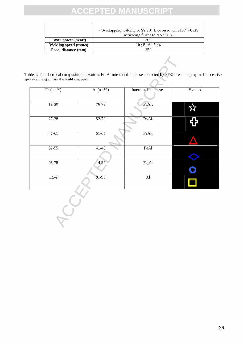
ACC
EPTE
D M
ANU
SCR
IPT
ACCEPTED MANUSCRIPT
29
- Overlapping welding of SS 304 L covered with TiO2+CaF2
activating fluxes to AA 5083.
Laser power (Watt) 300
Welding speed (mm/s) 10 ; 8 ; 6 ; 5 ; 4
Focal distance (mm) 350
Table 4: The chemical composition of various Fe-Al intermetallic phases detected by EDX area mapping and successive
spot scanning across the weld nuggets
Fe (at. %) Al (at. %) Intermetallic phases Symbol
18-20 76-78 FeAl3
27-38 52-73 Fe2Al5
47-61 51-65 FeAl2
52-55 41-45 FeAl
68-78 14-26 Fe3Al
1.5-2 91-93 Al

ACC
EPTE
D M
ANU
SCR
IPT
ACCEPTED MANUSCRIPT
30
Graphical abstract

ACC
EPTE
D M
ANU
SCR
IPT
ACCEPTED MANUSCRIPT
31
Highlights:
1) Steel-aluminum welding was performed by fiber laser using pre-placed activating flux.
2) Activating flux accelerates laser-matter coupling leading to shorter thermal cycle.
3) Shorter thermal cycle can restrict Fe-Al intermetallics formation.
4) Up to 1.85 times improvement in shear strength achieved after using activating flux.