ems-92199b electronic monitoring systems files/engine controls/ems447.8.bulletin.pdf · field...
TRANSCRIPT

EMS-92199BRevised 05-03
Catalog Section 40(00-02-0101)Electronic Monitoring Systems
EMS447 / EMS448 ControllersFull Equipment Protection (1)
Field Adjustable Parameters (1)
First-Out Shutdowns and/or Alarms (1)
Shutdown History File (1)
Service Reminders (1)
Back Lit LCD or VFD Alphanumeric Display1/4 DIN or NEMA 4X Enclosed Models Patent
Pending
DescriptionThe EMS447 and EMS448 Electronic MonitoringSystems/Controllers are micro-processor based formonitoring and control of equipment functions. Thebasic EMS system is programmed for a typicalindustrial engine power unit. Custom programmingis available to adapt the EMS to a wide variety ofengine and equipment requirements.Basic programs provide auto-start/manual start andfirst-out shutdown for engine functions such as pres-sure, temperature, level and overspeed. Necessarytime delays for start up lockout are included.Operating data is displayed on a 32 character backlit alphanumeric liquid crystal display. The EMS operating parameters are configuredthrough a simple three-button interface. Access tothe system memory is controlled by entry codes.A password-protected program uses built-in memo-ry to display the alarm/shutdown history, includinga display of the last ten shutdowns, when and whythey occurred and displays all of the engine operat-ing conditions at time of last shutdown.
Basic Program FeaturesAn on-board hourmeter keeps a log of equipmentrunning hours and alerts you when to change oil,filters and perform other routine service.Ramp Oil Pressure monitoring protects equip-ment at both high rated speed and low idle speed.For instance, based on engine manufacturer’srequirement, shutdown could occur at 30 lb. (207kPa) pressure at 1800 RPM or at 5 lb. (34 kPa) at600 RPM or any shutdown point in between.
Basic ModelsEMS448 has an extruded aluminum enclosure
suitable for panel mounting. Wiring is viaoptional wiring harness. Relay boards areavailable for additional relay contact capabil-ity. Refer to “Accessories” on the back page.
EMS448 has a NEMA 4X type enclosure. Wiring isconnected directly to the relay board terminalblock located within the enclosure. Relay boardfor additional relay contact capability is avail-able. See “Optional Accessories” on reverse side.
ApplicationsIndustrial Engines CompressorsGenerators TrucksConstruction Equipment Pumps
SpecificationsInput Voltage: 10 to 28 VDC.Operating Temperature: -4 to 149°F (-20 to 65°C).Storage Temperature: -4 to 149°F (-20 to 65°C).Display: Alphanumeric: 2-line, 32 character backlit LCD (standard); VFD optional.Relative Humidity: 95%RH @ 140°F (60°C).Communications: RS485 port, standard.Sensor Inputs:• Digital: 3-optically-isolated inputs, (positive volt-
age or ground) such as from Murphy SWICH-GAGE® instruments.(2)(3)
• Analog: Up to 8 inputs–accepts a variety of resis-tive sending units, such as from Murphy electricgage senders. NOTE: When resistive sendingunits are used, one input will be designated for battery voltage sensing. The use of 2-wire typesenders is strongly recommended. Special orderanalog inputs available (4-20 mA or 0-5 VDC).
• Frequency: 1 optically-isolated input for speed reference, such as MP3298 magnetic sensor.
EMS447 Outputs: • 3-Transistor digital: 125 mA sinking.(4)
• 3-Relay: SPST 3A @ 30VDC N.O. connected tobattery positive*.
• S449-4 Relay Board (optional)*:2-Transistor digital: 125 mA sinking. 4-Relay: 2-SPST, 5A @ 30 VDC, 250 VAC,
1/10 hp @ 120 VAC; (4)
2-DPDT, 2A @ 220 VDC,250 VAC. (5)
• S449-2 Relay Board (optional)*: 6-Dry Relay: 4 SPST, 5A @ 30 VDC, 250 VAC,
1/10 hp @ 120 VAC; (4)
2 DPDT, 2A @ 220 VDC, 250 VAC. (5)
EMS448 Outputs: • 2-Transistor digital: 125 mA sinking. • 4-Relay: 2-SPST, 5A @ 30 VDC, 250 VAC*,
1/10 hp @ 120 VAC; (4)
2-DPDT, 2A @ 220 VDC,250 VAC. (4)
• S449-1 Relay Board (optional)*: 6-Dry Relay: 4 SPST, 5A @ 30 VDC, 250 VAC,
1/10 hp @ 120 VAC; (4)
2 DPDT, 2A @ 220 VDC, 250 VAC. (5)
Shipping Weights andDimensionsEMS447: 2-1/4 lb (1 kg); 9-1/4 x 8-1/4 x 5-1/4 in. (235
x 210 x 133 mm).EMS448: 3-1/2 lb (1.5 kg); 12-1/4 x 7-1/4 x 5-3/4 in.
(311 x 184 x 146 mm).(1) Program specific. (2) One additional input can be ordered and traded for one transistor output.(3) Isolates the internal circuitry of the Murphy EMS from the sensor
input circuitry to help avoid electrical noise and damage.(4) One additional output can be ordered and traded for one digital input.(5) One DPDT pole has common connected to battery+. N.O. available
fused and unfused.*Not Class I, Division 2 approved.
EMS447
R
Approved for Cl. I,Div. 2, Grps. C & Dareas on EMS447 (all transistor out-puts) and EMS448(board only).
RC
EMS448
Bulletin EMS-92199B page 2 of 2
Front
5-43/64 in.(144 mm)
4-5/16 in.(110 mm)
.540 in.(13.716 mm)
8 in. (203 mm)Clearance for Connectors
2-5/8 in.(67 mm)
5-11/32 in.(135 mm)
Rear
2-7/8 in.(73 mm)
2-43/64 in. (68 mm)
5-3/8 in. (137 mm)
Side
Mounting Hole
EMS2-5/8 in.(67 mm)
¥¥¥¥¥¥¥¥¥¥¥¥¥¥¥¥¥¥¥¥¥¥¥¥¥¥¥¥
8-15/16 in.(227 mm)
EMS
8-1/2 in.(216 mm)
4 in.(102 mm)
4-3/4 in.(121 mm)
6-7/8 in.(175 mm)
5/16 x 1/2 in. (8 x 13 mm)Mounting Holes, 4-Places
ediStnorF
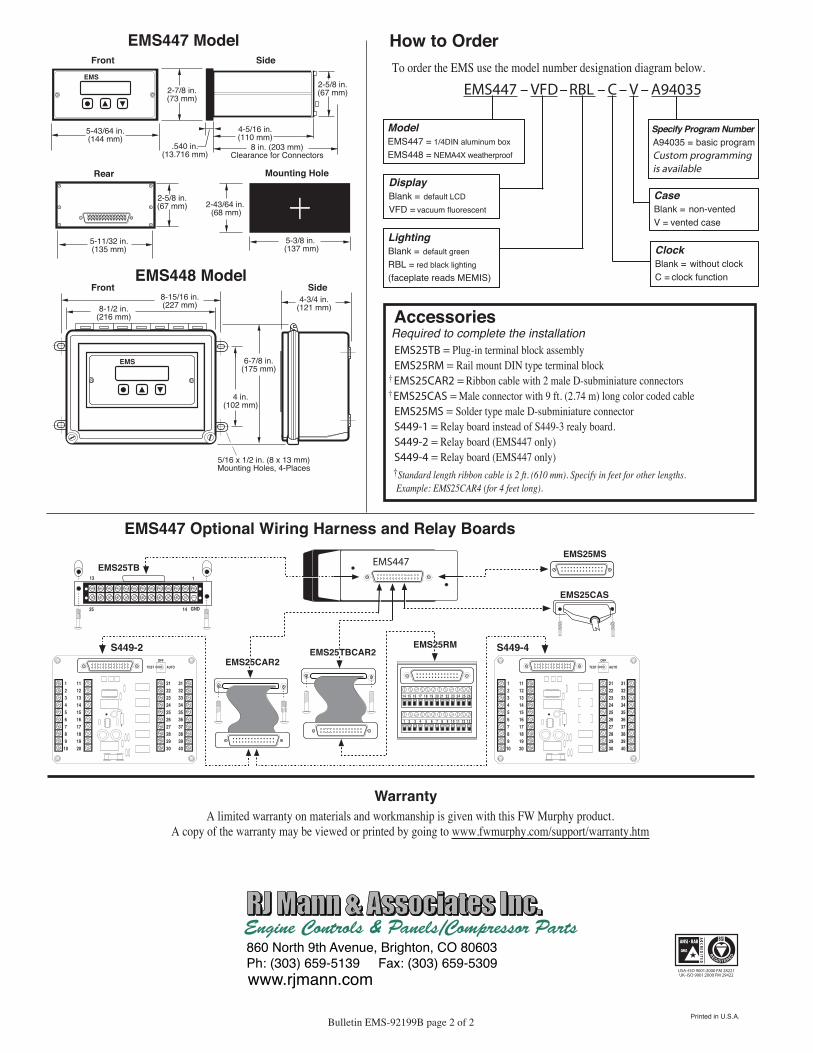
EMS447 Model
EMS448 Model
EMS447 Optional Wiring Harness and Relay Boards
14 15 16 17 18
1 2 3 4 5 6
19 20 21 22 23 24 25 26
7 8 9 10 11 12 13
••••••••••••••••••••••••••••
EMS447 EMS25TB
EMS25RM
EMS25CAS
EMS25MS
•• •• •• •• •• •• •• •• •• •• •• •• •• ••113
14 GND25
EMS25CAR2EMS25TBCAR2
••••••••••••••••••••••••••••
•• •• •• •• •• •• •• •• •• •• •• •• •• ••
S449-2
123456789
10
11121314151617181920
21222324252627282930
TEST AUTO
OFF
31323334353637383940
•• •• •• •• •• •• •• •• •• •• •• •• •• ••
S449-4
123456789
10
11121314151617181920
21222324252627282930
TEST AUTO
OFF
31323334353637383940
•• •• •• •• •• •• •• •• •• •• •• •• •• ••
••••••••••••••••••••••••••••
How to OrderTo order the EMS use the model number designation diagram below.
LightingBlank = default greenRBL = red black lighting(faceplate reads MEMIS)
ModelEMS447 = 1/4DIN aluminum boxEMS448 = NEMA4X weatherproof
DisplayBlank = default LCDVFD = vacuum fluorescent
Specify Program NumberA94035 = basic programCustom programming is available
CaseBlank = non-ventedV = vented case
ClockBlank = without clockC = clock function
EMS447 – VFD–RBL – C – V – A94035
AccessoriesRequired to complete the installationEMS25TB = Plug-in terminal block assemblyEMS25RM = Rail mount DIN type terminal block
† EMS25CAR2 = Ribbon cable with 2 male D-subminiature connectors† EMS25CAS = Male connector with 9 ft. (2.74 m) long color coded cable
EMS25MS = Solder type male D-subminiature connectorS449-1 = Relay board instead of S449-3 realy board.S449-2 = Relay board (EMS447 only)S449-4 = Relay board (EMS447 only)†Standard length ribbon cable is 2 ft. (610 mm). Specify in feet for other lengths. Example: EMS25CAR4 (for 4 feet long).
WarrantyA limited warranty on materials and workmanship is given with this FW Murphy product.
A copy of the warranty may be viewed or printed by going to www.fwmurphy.com/support/warranty.htm
REGISTERED
USA–ISO 9001:2000 FM 28221UK–ISO 9001:2000 FM 29422
Printed in U.S.A.