emu tutorial
DESCRIPTION
retertTRANSCRIPT
flat assemblerDocumentation and tutorials.
Main index Download Documentation Examples Message board
flat assembler 1.71Programmer's ManualTable of Contents
Chapter 1 - Introduction
1.1 Compiler overview1.1.1 System requirements1.1.2 Executing compiler from command line1.1.3 Compiler messages1.1.4 Output formats
1.2 Assembly syntax1.2.1 Instruction syntax1.2.2 Data definitions1.2.3 Constants and labels1.2.4 Numerical expressions1.2.5 Jumps and calls1.2.6 Size settings
Chapter 2 - Instruction Set
2.1 The x86 architecture instructions2.1.1 Data movement instructions2.1.2 Type conversion instructions2.1.3 Binary arithmetic instructions2.1.4 Decimal arithmetic instructions2.1.5 Logical instructions2.1.6 Control transfer instructions2.1.7 I/O instructions2.1.8 Strings operations2.1.9 Flag control instructions2.1.10 Conditional operations2.1.11 Miscellaneous instructions2.1.12 System instructions2.1.13 FPU instructions2.1.14 MMX instructions2.1.15 SSE instructions2.1.16 SSE2 instructions2.1.17 SSE3 instructions2.1.18 AMD 3DNow! instructions2.1.19 The x86-64 long mode instructions2.1.20 SSE4 instructions2.1.21 AVX instructions2.1.22 AVX2 instructions2.1.23 Auxiliary sets of computational instructions2.1.24 Other extensions of instruction set
2.2 Control directives2.2.1 Numerical constants2.2.2 Conditional assembly2.2.3 Repeating blocks of instructions2.2.4 Addressing spaces2.2.5 Other directives2.2.6 Multiple passes
2.3 Preprocessor directives2.3.1 Including source files2.3.2 Symbolic constants2.3.3 Macroinstructions2.3.4 Structures2.3.5 Repeating macroinstructions2.3.6 Conditional preprocessing2.3.7 Order of processing
2.4 Formatter directives2.4.1 MZ executable
2.4.2 Portable Executable2.4.3 Common Object File Format2.4.4 Executable and Linkable FormatChapter 1IntroductionThis chapter contains all the most important information you need to begin using the flat assembler. If you are experienced assembly language programmer, you should read at least this chapter before using this compiler.1.1 Compiler overviewFlat assembler is a fast assembly language compiler for the x86 architecture processors, which does multiple passes to optimize the size of generated machine code. It is self-compilable and versions for different operating systems are provided. All the versions are designed to be used from the system command line and they should not differ in behavior.1.1.1 System requirementsAll versions require the x86 architecture 32-bit processor (at least 80386), although they can produce programs for the x86 architecture 16-bit processors, too. DOS version requires an OS compatible with MS DOS 2.0 and either true real mode environment or DPMI. Windows version requires a Win32 console compatible with 3.1 version.1.1.2 Executing compiler from command lineTo execute flat assembler from the command line you need to provide two parameters - first should be name of source file, second should be name of destination file. If no second parameter is given, the name for output file will be guessed automatically. After displaying short information about the program name and version, compiler will read the data from source file and compile it. When the compilation is successful, compiler will write the generated code to the destination file and display the summary of compilation process; otherwise it will display the information about error that occurred.In the command line you can also include -m option followed by a number, which specifies how many kilobytes of memory flat assembler should maximally use. In case of DOS version this options limits only the usage of extended memory. The -p option followed by a number can be used to specify the limit for number of passes the assembler performs. If code cannot be generated within specified amount of passes, the assembly will be terminated with an error message. The maximum value of this setting is 65536, while the default limit, used when no such option is included in command line, is 100.The source file should be a text file, and can be created in any text editor. Line breaks are accepted in both DOS and Unix standards, tabulators are treated as spaces.There are no command line options that would affect the output of compiler, flat assembler requires only the source code to include the information it really needs. For example, to specify output format you specify it by using the format directive at the beginning of source.1.1.3 Compiler messagesAs it is stated above, after the successful compilation, the compiler displays the compilation summary. It includes the information of how many passes was done, how much time it took, and how many bytes were written into the destination file. The following is an example of the compilation summary:flat assembler version 1.70 (16384 kilobytes memory)38 passes, 5.3 seconds, 77824 bytes.In case of error during the compilation process, the program will display an error message. For example, when compiler can't find the input file, it will display the following message:flat assembler version 1.70 (16384 kilobytes memory)error: source file not found.If the error is connected with a specific part of source code, the source line that caused the error will be also displayed. Also placement of this line in the source is given to help you finding this error, for example:flat assembler version 1.70 (16384 kilobytes memory)example.asm [3]: mob ax,1error: illegal instruction.It means that in the third line of the example.asm file compiler has encountered an unrecognized instruction. When the line that caused error contains a macroinstruction, also the line in macroinstruction definition that generated the erroneous instruction is displayed:flat assembler version 1.70 (16384 kilobytes memory)example.asm [6]: stoschar 7example.asm [3] stoschar [1]: mob al,charerror: illegal instruction.It means that the macroinstruction in the sixth line of the example.asm file generated an unrecognized instruction with the first line of its definition.1.1.4 Output formatsBy default, when there is no format directive in source file, flat assembler simply puts generated instruction codes into output, creating this way flat binary file. By default it generates 16-bit code, but you can always turn it into the 16-bit or 32-bit mode by using use16 or use32 directive. Some of the output formats switch into 32-bit mode, when selected - more information about formats which you can choose can be found in 2.4.All output code is always in the order in which it was entered into the source file.1.2 Assembly syntaxThe information provided below is intended mainly for the assembler programmers that have been using some other assembly compilers before. If you are beginner, you should look for the assembly programming tutorials.Flat assembler by default uses the Intel syntax for the assembly instructions, although you can customize it using the preprocessor capabilities (macroinstructions and symbolic constants). It also has its own set of the directives - the instructions for compiler.
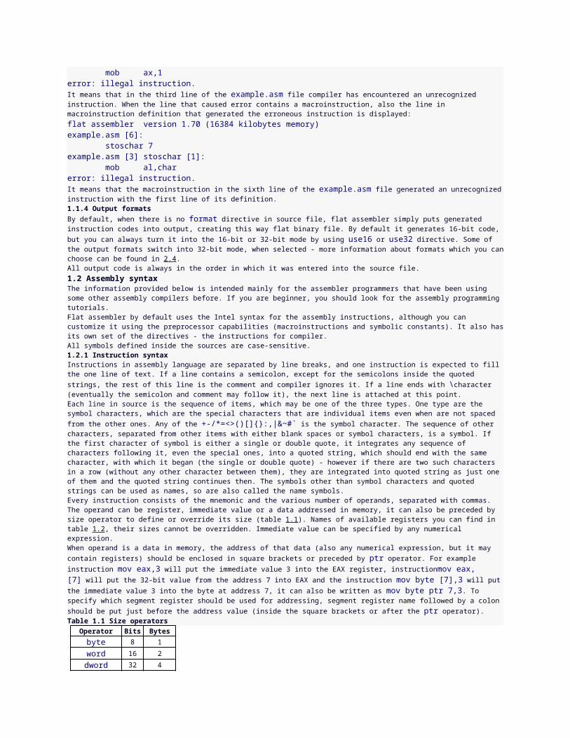
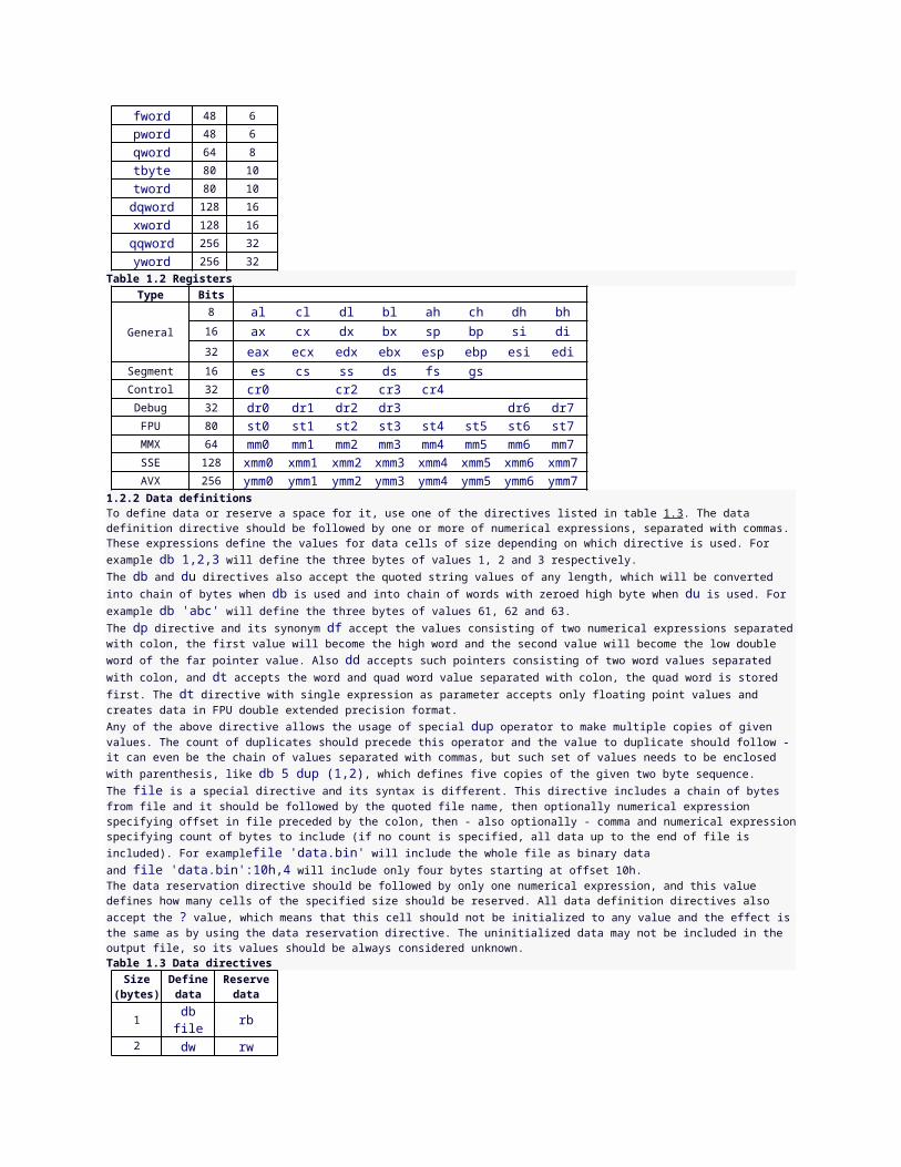
All symbols defined inside the sources are case-sensitive.1.2.1 Instruction syntaxInstructions in assembly language are separated by line breaks, and one instruction is expected to fill the one line of text. If a line contains a semicolon, except for the semicolons inside the quoted strings, the rest of this line is the comment and compiler ignores it. If a line ends with \character (eventually the semicolon and comment may follow it), the next line is attached at this point.Each line in source is the sequence of items, which may be one of the three types. One type are the symbol characters, which are the special characters that are individual items even when are not spaced from the other ones. Any of the +-/*=<>()[]{}:,|&~#` is the symbol character. The sequence of other characters, separated from other items with either blank spaces or symbol characters, is a symbol. If the first character of symbol is either a single or double quote, it integrates any sequence of characters following it, even the special ones, into a quoted string, which should end with the same character, with which it began (the single or double quote) - however if there are two such characters in a row (without any other character between them), they are integrated into quoted string as just one of them and the quoted string continues then. The symbols other than symbol characters and quoted strings can be used as names, so are also called the name symbols.Every instruction consists of the mnemonic and the various number of operands, separated with commas. The operand can be register, immediate value or a data addressed in memory, it can also be preceded by size operator to define or override its size (table 1.1). Names of available registers you can find in table 1.2, their sizes cannot be overridden. Immediate value can be specified by any numerical expression.When operand is a data in memory, the address of that data (also any numerical expression, but it may contain registers) should be enclosed in square brackets or preceded by ptr operator. For example instruction mov eax,3 will put the immediate value 3 into the EAX register, instructionmov eax,[7] will put the 32-bit value from the address 7 into EAX and the instruction mov byte [7],3 will put the immediate value 3 into the byte at address 7, it can also be written as mov byte ptr 7,3. To specify which segment register should be used for addressing, segment register name followed by a colon should be put just before the address value (inside the square brackets or after the ptr operator).Table 1.1 Size operators
Operator Bits Bytesbyte 8 1word 16 2dword 32 4fword 48 6pword 48 6qword 64 8tbyte 80 10tword 80 10dqword 128 16xword 128 16qqword 256 32yword 256 32
Table 1.2 RegistersType Bits
General
8 al cl dl bl ah ch dh bh16 ax cx dx bx sp bp si di
32 eax ecx edx ebx esp ebp esi ediSegment 16 es cs ss ds fs gs Control 32 cr0 cr2 cr3 cr4 Debug 32 dr0 dr1 dr2 dr3 dr6 dr7
FPU 80 st0 st1 st2 st3 st4 st5 st6 st7MMX 64 mm0 mm1 mm2 mm3 mm4 mm5 mm6 mm7SSE 128 xmm0 xmm1 xmm2 xmm3 xmm4 xmm5 xmm6 xmm7AVX 256 ymm0 ymm1 ymm2 ymm3 ymm4 ymm5 ymm6 ymm7
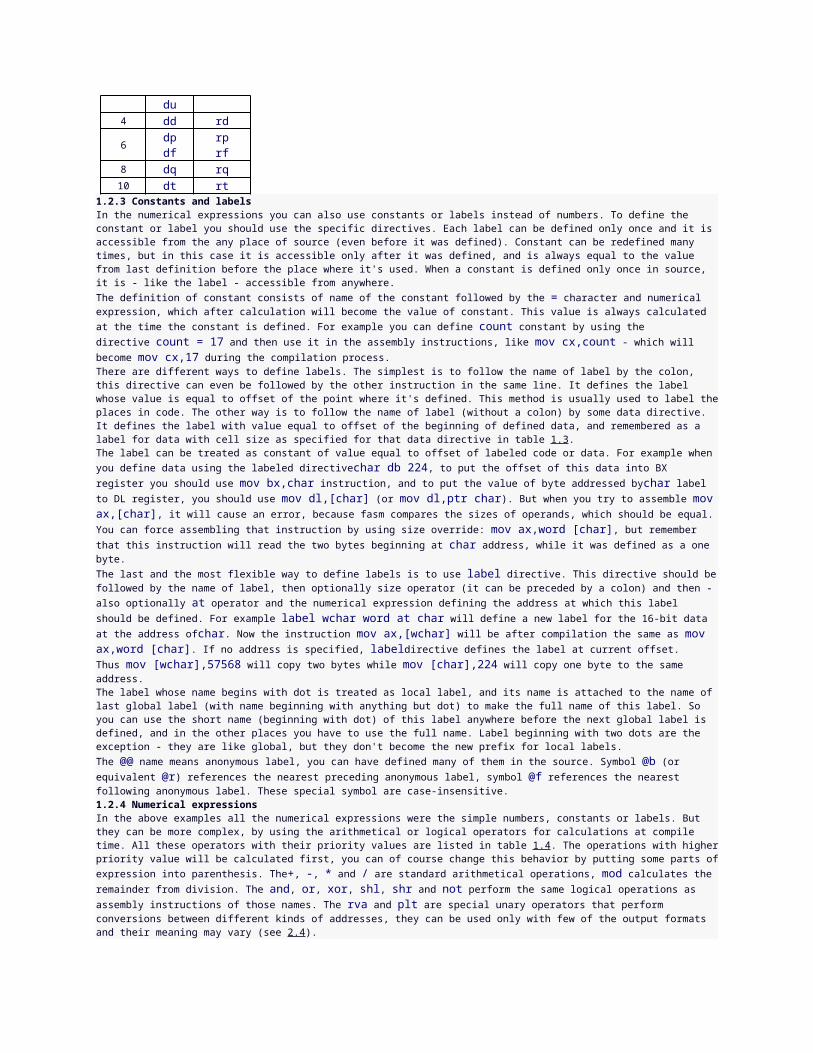
1.2.2 Data definitionsTo define data or reserve a space for it, use one of the directives listed in table 1.3. The data definition directive should be followed by one or more of numerical expressions, separated with commas. These expressions define the values for data cells of size depending on which directive is used. For example db 1,2,3 will define the three bytes of values 1, 2 and 3 respectively.The db and du directives also accept the quoted string values of any length, which will be converted into chain of bytes when db is used and into chain of words with zeroed high byte when du is used. For example db 'abc' will define the three bytes of values 61, 62 and 63.The dp directive and its synonym df accept the values consisting of two numerical expressions separated with colon, the first value will become the high word and the second value will become the low double word of the far pointer value. Also dd accepts such pointers consisting of two word values separated with colon, and dt accepts the word and quad word value separated with colon, the quad word is stored first. The dt directive with single expression as parameter accepts only floating point values and creates data in FPU double extended precision format.Any of the above directive allows the usage of special dup operator to make multiple copies of given values. The count of duplicates should precede this operator and the value to duplicate should follow - it can even be the chain of values
separated with commas, but such set of values needs to be enclosed with parenthesis, like db 5 dup (1,2), which defines five copies of the given two byte sequence.The file is a special directive and its syntax is different. This directive includes a chain of bytes from file and it should be followed by the quoted file name, then optionally numerical expression specifying offset in file preceded by the colon, then - also optionally - comma and numerical expression specifying count of bytes to include (if no count is specified, all data up to the end of file is included). For examplefile 'data.bin' will include the whole file as binary data and file 'data.bin':10h,4 will include only four bytes starting at offset 10h.The data reservation directive should be followed by only one numerical expression, and this value defines how many cells of the specified size should be reserved. All data definition directives also accept the ? value, which means that this cell should not be initialized to any value and the effect is the same as by using the data reservation directive. The uninitialized data may not be included in the output file, so its values should be always considered unknown.Table 1.3 Data directives
Size (bytes)
Define data
Reserve data
1dbfile rb
2dwdu rw
4 dd rd
6dpdf
rprf
8 dq rq10 dt rt
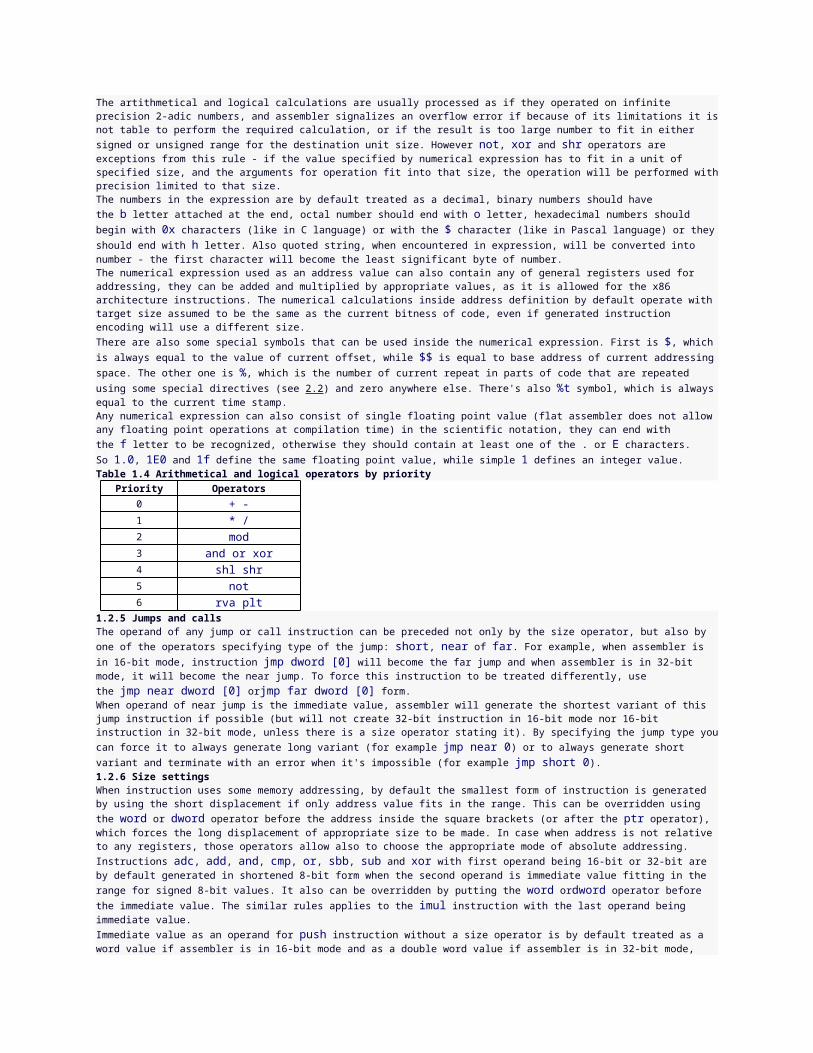
1.2.3 Constants and labelsIn the numerical expressions you can also use constants or labels instead of numbers. To define the constant or label you should use the specific directives. Each label can be defined only once and it is accessible from the any place of source (even before it was defined). Constant can be redefined many times, but in this case it is accessible only after it was defined, and is always equal to the value from last definition before the place where it's used. When a constant is defined only once in source, it is - like the label - accessible from anywhere.The definition of constant consists of name of the constant followed by the = character and numerical expression, which after calculation will become the value of constant. This value is always calculated at the time the constant is defined. For example you can define count constant by using the directive count = 17 and then use it in the assembly instructions, like mov cx,count - which will become mov cx,17 during the compilation process.There are different ways to define labels. The simplest is to follow the name of label by the colon, this directive can even be followed by the other instruction in the same line. It defines the label whose value is equal to offset of the point where it's defined. This method is usually used to label the places in code. The other way is to follow the name of label (without a colon) by some data directive. It defines the label with value equal to offset of the beginning of defined data, and remembered as a label for data with cell size as specified for that data directive in table 1.3.The label can be treated as constant of value equal to offset of labeled code or data. For example when you define data using the labeled directivechar db 224, to put the offset of this data into BX register you should use mov bx,char instruction, and to put the value of byte addressed bychar label to DL register, you should use mov dl,[char] (or mov dl,ptr char). But when you try to assemble mov ax,[char], it will cause an error, because fasm compares the sizes of operands, which should be equal. You can force assembling that instruction by using size override: mov ax,word [char], but remember that this instruction will read the two bytes beginning at char address, while it was defined as a one byte.The last and the most flexible way to define labels is to use label directive. This directive should be followed by the name of label, then optionally size operator (it can be preceded by a colon) and then - also optionally at operator and the numerical expression defining the address at which this label should be defined. For example label wchar word at char will define a new label for the 16-bit data at the address ofchar. Now the instruction mov ax,[wchar] will be after compilation the same as mov ax,word [char]. If no address is specified, labeldirective defines the label at current offset. Thus mov [wchar],57568 will copy two bytes while mov [char],224 will copy one byte to the same address.The label whose name begins with dot is treated as local label, and its name is attached to the name of last global label (with name beginning with anything but dot) to make the full name of this label. So you can use the short name (beginning with dot) of this label anywhere before the next global label is defined, and in the other places you have to use the full name. Label beginning with two dots are the exception - they are like global, but they don't become the new prefix for local labels.The @@ name means anonymous label, you can have defined many of them in the source. Symbol @b (or equivalent @r) references the nearest preceding anonymous label, symbol @f references the nearest following anonymous label. These special symbol are case-insensitive.1.2.4 Numerical expressionsIn the above examples all the numerical expressions were the simple numbers, constants or labels. But they can be more complex, by using the arithmetical or logical operators for calculations at compile time. All these operators with their priority values are listed in table 1.4. The operations with higher priority value will be calculated first, you can of course change this behavior by putting some parts of expression into parenthesis. The+, -, * and / are standard arithmetical operations, mod calculates the remainder from division. The and, or, xor, shl, shr and not perform the same logical operations as assembly instructions of those names. The rva and plt are special unary operators that perform conversions between different kinds of addresses, they can be used only with few of the output formats and their meaning may vary (see 2.4).The artithmetical and logical calculations are usually processed as if they operated on infinite precision 2-adic numbers, and assembler signalizes an overflow error if because of its limitations it is not table to perform the required calculation, or
if the result is too large number to fit in either signed or unsigned range for the destination unit size. However not, xor and shr operators are exceptions from this rule - if the value specified by numerical expression has to fit in a unit of specified size, and the arguments for operation fit into that size, the operation will be performed with precision limited to that size.The numbers in the expression are by default treated as a decimal, binary numbers should have the b letter attached at the end, octal number should end with o letter, hexadecimal numbers should begin with 0x characters (like in C language) or with the $ character (like in Pascal language) or they should end with h letter. Also quoted string, when encountered in expression, will be converted into number - the first character will become the least significant byte of number.The numerical expression used as an address value can also contain any of general registers used for addressing, they can be added and multiplied by appropriate values, as it is allowed for the x86 architecture instructions. The numerical calculations inside address definition by default operate with target size assumed to be the same as the current bitness of code, even if generated instruction encoding will use a different size.There are also some special symbols that can be used inside the numerical expression. First is $, which is always equal to the value of current offset, while $$ is equal to base address of current addressing space. The other one is %, which is the number of current repeat in parts of code that are repeated using some special directives (see 2.2) and zero anywhere else. There's also %t symbol, which is always equal to the current time stamp.Any numerical expression can also consist of single floating point value (flat assembler does not allow any floating point operations at compilation time) in the scientific notation, they can end with the f letter to be recognized, otherwise they should contain at least one of the . or E characters. So 1.0, 1E0 and 1f define the same floating point value, while simple 1 defines an integer value.Table 1.4 Arithmetical and logical operators by priority
Priority Operators0 + -1 * /2 mod3 and or xor4 shl shr5 not6 rva plt
1.2.5 Jumps and callsThe operand of any jump or call instruction can be preceded not only by the size operator, but also by one of the operators specifying type of the jump: short, near of far. For example, when assembler is in 16-bit mode, instruction jmp dword [0] will become the far jump and when assembler is in 32-bit mode, it will become the near jump. To force this instruction to be treated differently, use the jmp near dword [0] orjmp far dword [0] form.When operand of near jump is the immediate value, assembler will generate the shortest variant of this jump instruction if possible (but will not create 32-bit instruction in 16-bit mode nor 16-bit instruction in 32-bit mode, unless there is a size operator stating it). By specifying the jump type you can force it to always generate long variant (for example jmp near 0) or to always generate short variant and terminate with an error when it's impossible (for example jmp short 0).1.2.6 Size settingsWhen instruction uses some memory addressing, by default the smallest form of instruction is generated by using the short displacement if only address value fits in the range. This can be overridden using the word or dword operator before the address inside the square brackets (or after the ptr operator), which forces the long displacement of appropriate size to be made. In case when address is not relative to any registers, those operators allow also to choose the appropriate mode of absolute addressing.Instructions adc, add, and, cmp, or, sbb, sub and xor with first operand being 16-bit or 32-bit are by default generated in shortened 8-bit form when the second operand is immediate value fitting in the range for signed 8-bit values. It also can be overridden by putting the word ordword operator before the immediate value. The similar rules applies to the imul instruction with the last operand being immediate value.Immediate value as an operand for push instruction without a size operator is by default treated as a word value if assembler is in 16-bit mode and as a double word value if assembler is in 32-bit mode, shorter 8-bit form of this instruction is used if possible, word or dword size operator forces the push instruction to be generated in longer form for specified size. pushw and pushd mnemonics force assembler to generate 16-bit or 32-bit code without forcing it to use the longer form of instruction.Chapter 2Instruction set2.1 The x86 architecture instructionsIn this section you can find both the information about the syntax and purpose the assembly language instructions. If you need more technical information, look for the Intel Architecture Software Developer's Manual.Assembly instructions consist of the mnemonic (instruction's name) and from zero to three operands. If there are two or more operands, usually first is the destination operand and second is the source operand. Each operand can be register, memory or immediate value (see 1.2 for details about syntax of operands). After the description of each instruction there are examples of different combinations of operands, if the instruction has any.Some instructions act as prefixes and can be followed by other instruction in the same line, and there can be more than one prefix in a line. Each name of the segment register is also a mnemonic of instruction prefix, altough it is recommended to use segment overrides inside the square brackets instead of these prefixes.2.1.1 Data movement instructionsmov transfers a byte, word or double word from the source operand to the destination operand. It can transfer data between general registers, from the general register to memory, or from memory to general register, but it cannot move
from memory to memory. It can also transfer an immediate value to general register or memory, segment register to general register or memory, general register or memory to segment register, control or debug register to general register and general register to control or debug register. The mov can be assembled only if the size of source operand and size of destination operand are the same. Below are the examples for each of the allowed combinations: mov bx,ax ; general register to general register mov [char],al ; general register to memory mov bl,[char] ; memory to general register mov dl,32 ; immediate value to general register mov [char],32 ; immediate value to memory mov ax,ds ; segment register to general register mov [bx],ds ; segment register to memory mov ds,ax ; general register to segment register mov ds,[bx] ; memory to segment register mov eax,cr0 ; control register to general register mov cr3,ebx ; general register to control registerxchg swaps the contents of two operands. It can swap two byte operands, two word operands or two double word operands. Order of operands is not important. The operands may be two general registers, or general register with memory. For example: xchg ax,bx ; swap two general registers xchg al,[char] ; swap register with memorypush decrements the stack frame pointer (ESP register), then transfers the operand to the top of stack indicated by ESP. The operand can be memory, general register, segment register or immediate value of word or double word size. If operand is an immediate value and no size is specified, it is by default treated as a word value if assembler is in 16-bit mode and as a double word value if assembler is in 32-bit mode. pushwand pushd mnemonics are variants of this instruction that store the values of word or double word size respectively. If more operands follow in the same line (separated only with spaces, not commas), compiler will assemble chain of the push instructions with these operands. The examples are with single operands: push ax ; store general register push es ; store segment register pushw [bx] ; store memory push 1000h ; store immediate valuepusha saves the contents of the eight general register on the stack. This instruction has no operands. There are two version of this instruction, one 16-bit and one 32-bit, assembler automatically generates the appropriate version for current mode, but it can be overridden by using pushaw orpushad mnemonic to always get the 16-bit or 32-bit version. The 16-bit version of this instruction pushes general registers on the stack in the following order: AX, CX, DX, BX, the initial value of SP before AX was pushed, BP, SI and DI. The 32-bit version pushes equivalent 32-bit general registers in the same order.pop transfers the word or double word at the current top of stack to the destination operand, and then increments ESP to point to the new top of stack. The operand can be memory, general register or segment register. popw and popd mnemonics are variants of this instruction for restoring the values of word or double word size respectively. If more operands separated with spaces follow in the same line, compiler will assemble chain of the pop instructions with these operands. pop bx ; restore general register pop ds ; restore segment register popw [si] ; restore memorypopa restores the registers saved on the stack by pusha instruction, except for the saved value of SP (or ESP), which is ignored. This instruction has no operands. To force assembling 16-bit or 32-bit version of this instruction use popaw or popad mnemonic.2.1.2 Type conversion instructionsThe type conversion instructions convert bytes into words, words into double words, and double words into quad words. These conversions can be done using the sign extension or zero extension. The sign extension fills the extra bits of the larger item with the value of the sign bit of the smaller item, the zero extension simply fills them with zeros.cwd and cdq double the size of value AX or EAX register respectively and store the extra bits into the DX or EDX register. The conversion is done using the sign extension. These instructions have no operands.cbw extends the sign of the byte in AL throughout AX, and cwde extends the sign of the word in AX throughout EAX. These instructions also have no operands.movsx converts a byte to word or double word and a word to double word using the sign extension. movzx does the same, but it uses the zero extension. The source operand can be general register or memory, while the destination operand must be a general register. For example: movsx ax,al ; byte register to word register movsx edx,dl ; byte register to double word register movsx eax,ax ; word register to double word register movsx ax,byte [bx] ; byte memory to word register movsx edx,byte [bx] ; byte memory to double word register movsx eax,word [bx] ; word memory to double word register2.1.3 Binary arithmetic instructionsadd replaces the destination operand with the sum of the source and destination operands and sets CF if overflow has occurred. The operands may be bytes, words or double words. The destination operand can be general register or memory, the source operand can be general register or immediate value, it can also be memory if the destination operand is register.
add ax,bx ; add register to register add ax,[si] ; add memory to register add [di],al ; add register to memory add al,48 ; add immediate value to register add [char],48 ; add immediate value to memoryadc sums the operands, adds one if CF is set, and replaces the destination operand with the result. Rules for the operands are the same as for theadd instruction. An add followed by multiple adc instructions can be used to add numbers longer than 32 bits.inc adds one to the operand, it does not affect CF. The operand can be general register or memory, and the size of the operand can be byte, word or double word. inc ax ; increment register by one inc byte [bx] ; increment memory by onesub subtracts the source operand from the destination operand and replaces the destination operand with the result. If a borrow is required, the CF is set. Rules for the operands are the same as for the add instruction.sbb subtracts the source operand from the destination operand, subtracts one if CF is set, and stores the result to the destination operand. Rules for the operands are the same as for the add instruction. A sub followed by multiple sbb instructions may be used to subtract numbers longer than 32 bits.dec subtracts one from the operand, it does not affect CF. Rules for the operand are the same as for the inc instruction.cmp subtracts the source operand from the destination operand. It updates the flags as the sub instruction, but does not alter the source and destination operands. Rules for the operands are the same as for the sub instruction.neg subtracts a signed integer operand from zero. The effect of this instructon is to reverse the sign of the operand from positive to negative or from negative to positive. Rules for the operand are the same as for the inc instruction.xadd exchanges the destination operand with the source operand, then loads the sum of the two values into the destination operand. Rules for the operands are the same as for the add instruction.All the above binary arithmetic instructions update SF, ZF, PF and OF flags. SF is always set to the same value as the result's sign bit, ZF is set when all the bits of result are zero, PF is set when low order eight bits of result contain an even number of set bits, OF is set if result is too large for a positive number or too small for a negative number (excluding sign bit) to fit in destination operand.mul performs an unsigned multiplication of the operand and the accumulator. If the operand is a byte, the processor multiplies it by the contents of AL and returns the 16-bit result to AH and AL. If the operand is a word, the processor multiplies it by the contents of AX and returns the 32-bit result to DX and AX. If the operand is a double word, the processor multiplies it by the contents of EAX and returns the 64-bit result in EDX and EAX. mul sets CF and OF when the upper half of the result is nonzero, otherwise they are cleared. Rules for the operand are the same as for theinc instruction.imul performs a signed multiplication operation. This instruction has three variations. First has one operand and behaves in the same way as themul instruction. Second has two operands, in this case destination operand is multiplied by the source operand and the result replaces the destination operand. Destination operand must be a general register, it can be word or double word, source operand can be general register, memory or immediate value. Third form has three operands, the destination operand must be a general register, word or double word in size, source operand can be general register or memory, and third operand must be an immediate value. The source operand is multiplied by the immediate value and the result is stored in the destination register. All the three forms calculate the product to twice the size of operands and set CF and OF when the upper half of the result is nonzero, but second and third form truncate the product to the size of operands. So second and third forms can be also used for unsigned operands because, whether the operands are signed or unsigned, the lower half of the product is the same. Below are the examples for all three forms: imul bl ; accumulator by register imul word [si] ; accumulator by memory imul bx,cx ; register by register imul bx,[si] ; register by memory imul bx,10 ; register by immediate value imul ax,bx,10 ; register by immediate value to register imul ax,[si],10 ; memory by immediate value to registerdiv performs an unsigned division of the accumulator by the operand. The dividend (the accumulator) is twice the size of the divisor (the operand), the quotient and remainder have the same size as the divisor. If divisor is byte, the dividend is taken from AX register, the quotient is stored in AL and the remainder is stored in AH. If divisor is word, the upper half of dividend is taken from DX, the lower half of dividend is taken from AX, the quotient is stored in AX and the remainder is stored in DX. If divisor is double word, the upper half of dividend is taken from EDX, the lower half of dividend is taken from EAX, the quotient is stored in EAX and the remainder is stored in EDX. Rules for the operand are the same as for the mul instruction.idiv performs a signed division of the accumulator by the operand. It uses the same registers as the div instruction, and the rules for the operand are the same.2.1.4 Decimal arithmetic instructionsDecimal arithmetic is performed by combining the binary arithmetic instructions (already described in the prior section) with the decimal arithmetic instructions. The decimal arithmetic instructions are used to adjust the results of a previous binary arithmetic operation to produce a valid packed or unpacked decimal result, or to adjust the inputs to a subsequent binary arithmetic operation so the operation will produce a valid packed or unpacked decimal result.daa adjusts the result of adding two valid packed decimal operands in AL. daa must always follow the addition of two pairs of packed decimal numbers (one digit in each half-byte) to obtain a pair of valid packed decimal digits as results. The carry flag is set if carry was needed. This instruction has no operands.das adjusts the result of subtracting two valid packed decimal operands in AL. das must always follow the subtraction of one pair of packed decimal numbers (one digit in each half-byte) from another to obtain a pair of valid packed decimal digits as results. The carry flag is set if a borrow was needed. This instruction has no operands.
aaa changes the contents of register AL to a valid unpacked decimal number, and zeroes the top four bits. aaa must always follow the addition of two unpacked decimal operands in AL. The carry flag is set and AH is incremented if a carry is necessary. This instruction has no operands.aas changes the contents of register AL to a valid unpacked decimal number, and zeroes the top four bits. aas must always follow the subtraction of one unpacked decimal operand from another in AL. The carry flag is set and AH decremented if a borrow is necessary. This instruction has no operands.aam corrects the result of a multiplication of two valid unpacked decimal numbers. aam must always follow the multiplication of two decimal numbers to produce a valid decimal result. The high order digit is left in AH, the low order digit in AL. The generalized version of this instruction allows adjustment of the contents of the AX to create two unpacked digits of any number base. The standard version of this instruction has no operands, the generalized version has one operand - an immediate value specifying the number base for the created digits.aad modifies the numerator in AH and AL to prepare for the division of two valid unpacked decimal operands so that the quotient produced by the division will be a valid unpacked decimal number. AH should contain the high order digit and AL the low order digit. This instruction adjusts the value and places the result in AL, while AH will contain zero. The generalized version of this instruction allows adjustment of two unpacked digits of any number base. Rules for the operand are the same as for the aam instruction.2.1.5 Logical instructionsnot inverts the bits in the specified operand to form a one's complement of the operand. It has no effect on the flags. Rules for the operand are the same as for the inc instruction.and, or and xor instructions perform the standard logical operations. They update the SF, ZF and PF flags. Rules for the operands are the same as for the add instruction.bt, bts, btr and btc instructions operate on a single bit which can be in memory or in a general register. The location of the bit is specified as an offset from the low order end of the operand. The value of the offset is the taken from the second operand, it either may be an immediate byte or a general register. These instructions first assign the value of the selected bit to CF. bt instruction does nothing more, bts sets the selected bit to 1, btr resets the selected bit to 0, btc changes the bit to its complement. The first operand can be word or double word. bt ax,15 ; test bit in register bts word [bx],15 ; test and set bit in memory btr ax,cx ; test and reset bit in register btc word [bx],cx ; test and complement bit in memorybsf and bsr instructions scan a word or double word for first set bit and store the index of this bit into destination operand, which must be general register. The bit string being scanned is specified by source operand, it may be either general register or memory. The ZF flag is set if the entire string is zero (no set bits are found); otherwise it is cleared. If no set bit is found, the value of the destination register is undefined. bsfscans from low order to high order (starting from bit index zero). bsr scans from high order to low order (starting from bit index 15 of a word or index 31 of a double word). bsf ax,bx ; scan register forward bsr ax,[si] ; scan memory reverseshl shifts the destination operand left by the number of bits specified in the second operand. The destination operand can be byte, word, or double word general register or memory. The second operand can be an immediate value or the CL register. The processor shifts zeros in from the right (low order) side of the operand as bits exit from the left side. The last bit that exited is stored in CF. sal is a synonym for shl. shl al,1 ; shift register left by one bit shl byte [bx],1 ; shift memory left by one bit shl ax,cl ; shift register left by count from cl shl word [bx],cl ; shift memory left by count from clshr and sar shift the destination operand right by the number of bits specified in the second operand. Rules for operands are the same as for theshl instruction. shr shifts zeros in from the left side of the operand as bits exit from the right side. The last bit that exited is stored in CF. sarpreserves the sign of the operand by shifting in zeros on the left side if the value is positive or by shifting in ones if the value is negative.shld shifts bits of the destination operand to the left by the number of bits specified in third operand, while shifting high order bits from the source operand into the destination operand on the right. The source operand remains unmodified. The destination operand can be a word or double word general register or memory, the source operand must be a general register, third operand can be an immediate value or the CL register. shld ax,bx,1 ; shift register left by one bit shld [di],bx,1 ; shift memory left by one bit shld ax,bx,cl ; shift register left by count from cl shld [di],bx,cl ; shift memory left by count from clshrd shifts bits of the destination operand to the right, while shifting low order bits from the source operand into the destination operand on the left. The source operand remains unmodified. Rules for operands are the same as for the shld instruction.rol and rcl rotate the byte, word or double word destination operand left by the number of bits specified in the second operand. For each rotation specified, the high order bit that exits from the left of the operand returns at the right to become the new low order bit. rcl additionally puts in CF each high order bit that exits from the left side of the operand before it returns to the operand as the low order bit on the next rotation cycle. Rules for operands are the same as for the shl instruction.ror and rcr rotate the byte, word or double word destination operand right by the number of bits specified in the second operand. For each rotation specified, the low order bit that exits from the right of the operand returns at the left to become the new high order bit. rcr additionally puts in CF each low order bit that exits from the right side of the operand before it
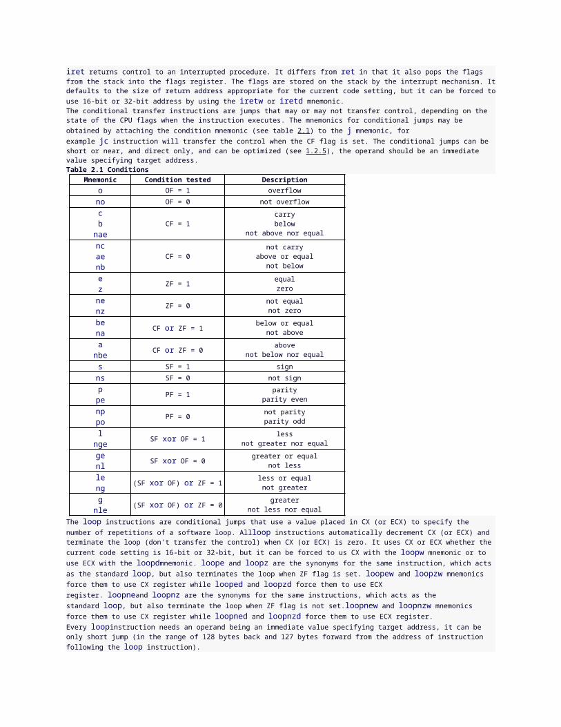
returns to the operand as the high order bit on the next rotation cycle. Rules for operands are the same as for the shl instruction.test performs the same action as the and instruction, but it does not alter the destination operand, only updates flags. Rules for the operands are the same as for the and instruction.bswap reverses the byte order of a 32-bit general register: bits 0 through 7 are swapped with bits 24 through 31, and bits 8 through 15 are swapped with bits 16 through 23. This instruction is provided for converting little-endian values to big-endian format and vice versa. bswap edx ; swap bytes in register2.1.6 Control transfer instructionsjmp unconditionally transfers control to the target location. The destination address can be specified directly within the instruction or indirectly through a register or memory, the acceptable size of this address depends on whether the jump is near or far (it can be specified by preceding the operand with near or far operator) and whether the instruction is 16-bit or 32-bit. Operand for near jump should be word size for 16-bit instruction or the dword size for 32-bit instruction. Operand for far jump should be dword size for 16-bit instruction or pword size for 32-bit instruction. A direct jmp instruction includes the destination address as part of the instruction (and can be preceded by short, near or faroperator), the operand specifying address should be the numerical expression for near or short jump, or two numerical expressions separated with colon for far jump, the first specifies selector of segment, the second is the offset within segment. The pword operator can be used to force the 32-bit far call, and dword to force the 16-bit far call. An indirect jmp instruction obtains the destination address indirectly through a register or a pointer variable, the operand should be general register or memory. See also 1.2.5 for some more details. jmp 100h ; direct near jump jmp 0FFFFh:0 ; direct far jump jmp ax ; indirect near jump jmp pword [ebx] ; indirect far jumpcall transfers control to the procedure, saving on the stack the address of the instruction following the call for later use by a ret (return) instruction. Rules for the operands are the same as for the jmp instruction, but the call has no short variant of direct instruction and thus it not optimized.ret, retn and retf instructions terminate the execution of a procedure and transfers control back to the program that originally invoked the procedure using the address that was stored on the stack by the call instruction. ret is the equivalent for retn, which returns from the procedure that was executed using the near call, while retf returns from the procedure that was executed using the far call. These instructions default to the size of address appropriate for the current code setting, but the size of address can be forced to 16-bit by using the retw, retnwand retfw mnemonics, and to 32-bit by using the retd, retnd and retfd mnemonics. All these instructions may optionally specify an immediate operand, by adding this constant to the stack pointer, they effectively remove any arguments that the calling program pushed on the stack before the execution of the call instruction.iret returns control to an interrupted procedure. It differs from ret in that it also pops the flags from the stack into the flags register. The flags are stored on the stack by the interrupt mechanism. It defaults to the size of return address appropriate for the current code setting, but it can be forced to use 16-bit or 32-bit address by using the iretw or iretd mnemonic.The conditional transfer instructions are jumps that may or may not transfer control, depending on the state of the CPU flags when the instruction executes. The mnemonics for conditional jumps may be obtained by attaching the condition mnemonic (see table 2.1) to the j mnemonic, for example jc instruction will transfer the control when the CF flag is set. The conditional jumps can be short or near, and direct only, and can be optimized (see 1.2.5), the operand should be an immediate value specifying target address.Table 2.1 Conditions
Mnemonic Condition tested Descriptiono OF = 1 overflowno OF = 0 not overflowcbnae
CF = 1carrybelow
not above nor equal
ncaenb
CF = 0not carry
above or equalnot below
ez ZF = 1
equalzero
nenz ZF = 0
not equalnot zero
bena CF or ZF = 1 below or equal
not aboveanbe CF or ZF = 0 above
not below nor equals SF = 1 signns SF = 0 not signppe PF = 1
parityparity even
np PF = 0 not parity
po parity oddlnge SF xor OF = 1 less
not greater nor equalgenl SF xor OF = 0 greater or equal
not lessleng (SF xor OF) or ZF = 1 less or equal
not greatergnle (SF xor OF) or ZF = 0 greater
not less nor equalThe loop instructions are conditional jumps that use a value placed in CX (or ECX) to specify the number of repetitions of a software loop. Allloop instructions automatically decrement CX (or ECX) and terminate the loop (don't transfer the control) when CX (or ECX) is zero. It uses CX or ECX whether the current code setting is 16-bit or 32-bit, but it can be forced to us CX with the loopw mnemonic or to use ECX with the loopdmnemonic. loope and loopz are the synonyms for the same instruction, which acts as the standard loop, but also terminates the loop when ZF flag is set. loopew and loopzw mnemonics force them to use CX register while looped and loopzd force them to use ECX register. loopneand loopnz are the synonyms for the same instructions, which acts as the standard loop, but also terminate the loop when ZF flag is not set.loopnew and loopnzw mnemonics force them to use CX register while loopned and loopnzd force them to use ECX register. Every loopinstruction needs an operand being an immediate value specifying target address, it can be only short jump (in the range of 128 bytes back and 127 bytes forward from the address of instruction following the loop instruction).jcxz branches to the label specified in the instruction if it finds a value of zero in CX, jecxz does the same, but checks the value of ECX instead of CX. Rules for the operands are the same as for the loop instruction.int activates the interrupt service routine that corresponds to the number specified as an operand to the instruction, the number should be in range from 0 to 255. The interrupt service routine terminates with an iret instruction that returns control to the instruction that follows int.int3 mnemonic codes the short (one byte) trap that invokes the interrupt 3. into instruction invokes the interrupt 4 if the OF flag is set.bound verifies that the signed value contained in the specified register lies within specified limits. An interrupt 5 occurs if the value contained in the register is less than the lower bound or greater than the upper bound. It needs two operands, the first operand specifies the register being tested, the second operand should be memory address for the two signed limit values. The operands can be word or dword in size. bound ax,[bx] ; check word for bounds bound eax,[esi] ; check double word for bounds2.1.7 I/O instructionsin transfers a byte, word, or double word from an input port to AL, AX, or EAX. I/O ports can be addressed either directly, with the immediate byte value coded in instruction, or indirectly via the DX register. The destination operand should be AL, AX, or EAX register. The source operand should be an immediate value in range from 0 to 255, or DX register. in al,20h ; input byte from port 20h in ax,dx ; input word from port addressed by dxout transfers a byte, word, or double word to an output port from AL, AX, or EAX. The program can specify the number of the port using the same methods as the in instruction. The destination operand should be an immediate value in range from 0 to 255, or DX register. The source operand should be AL, AX, or EAX register. out 20h,ax ; output word to port 20h out dx,al ; output byte to port addressed by dx2.1.8 Strings operationsThe string operations operate on one element of a string. A string element may be a byte, a word, or a double word. The string elements are addressed by SI and DI (or ESI and EDI) registers. After every string operation SI and/or DI (or ESI and/or EDI) are automatically updated to point to the next element of the string. If DF (direction flag) is zero, the index registers are incremented, if DF is one, they are decremented. The amount of the increment or decrement is 1, 2, or 4 depending on the size of the string element. Every string operation instruction has short forms which have no operands and use SI and/or DI when the code type is 16-bit, and ESI and/or EDI when the code type is 32-bit. SI and ESI by default address data in the segment selected by DS, DI and EDI always address data in the segment selected by ES. Short form is obtained by attaching to the mnemonic of string operation letter specifying the size of string element, it should be b for byte element, w for word element, andd for double word element. Full form of string operation needs operands providing the size operator and the memory addresses, which can be SI or ESI with any segment prefix, DI or EDI always with ES segment prefix.movs transfers the string element pointed to by SI (or ESI) to the location pointed to by DI (or EDI). Size of operands can be byte, word, or double word. The destination operand should be memory addressed by DI or EDI, the source operand should be memory addressed by SI or ESI with any segment prefix. movs byte [di],[si] ; transfer byte movs word [es:di],[ss:si] ; transfer word movsd ; transfer double wordcmps subtracts the destination string element from the source string element and updates the flags AF, SF, PF, CF and OF, but it does not change any of the compared elements. If the string elements are equal, ZF is set, otherwise it is cleared. The first operand for this instruction should be the source string element addressed by SI or ESI with any segment prefix, the second operand should be the destination string element addressed by DI or EDI. cmpsb ; compare bytes cmps word [ds:si],[es:di] ; compare words cmps dword [fs:esi],[edi] ; compare double words
scas subtracts the destination string element from AL, AX, or EAX (depending on the size of string element) and updates the flags AF, SF, ZF, PF, CF and OF. If the values are equal, ZF is set, otherwise it is cleared. The operand should be the destination string element addressed by DI or EDI. scas byte [es:di] ; scan byte scasw ; scan word scas dword [es:edi] ; scan double wordstos places the value of AL, AX, or EAX into the destination string element. Rules for the operand are the same as for the scas instruction.lods places the source string element into AL, AX, or EAX. The operand should be the source string element addressed by SI or ESI with any segment prefix. lods byte [ds:si] ; load byte lods word [cs:si] ; load word lodsd ; load double wordins transfers a byte, word, or double word from an input port addressed by DX register to the destination string element. The destination operand should be memory addressed by DI or EDI, the source operand should be the DX register. insb ; input byte ins word [es:di],dx ; input word ins dword [edi],dx ; input double wordouts transfers the source string element to an output port addressed by DX register. The destination operand should be the DX register and the source operand should be memory addressed by SI or ESI with any segment prefix. outs dx,byte [si] ; output byte outsw ; output word outs dx,dword [gs:esi] ; output double wordThe repeat prefixes rep, repe/repz, and repne/repnz specify repeated string operation. When a string operation instruction has a repeat prefix, the operation is executed repeatedly, each time using a different element of the string. The repetition terminates when one of the conditions specified by the prefix is satisfied. All three prefixes automatically decrease CX or ECX register (depending whether string operation instruction uses the 16-bit or 32-bit addressing) after each operation and repeat the associated operation until CX or ECX is zero. repe/repz andrepne/repnz are used exclusively with the scas and cmps instructions (described below). When these prefixes are used, repetition of the next instruction depends on the zero flag (ZF) also, repe and repz terminate the execution when the ZF is zero, repne and repnz terminate the execution when the ZF is set. rep movsd ; transfer multiple double words repe cmpsb ; compare bytes until not equal2.1.9 Flag control instructionsThe flag control instructions provide a method for directly changing the state of bits in the flag register. All instructions described in this section have no operands.stc sets the CF (carry flag) to 1, clc zeroes the CF, cmc changes the CF to its complement. std sets the DF (direction flag) to 1, cld zeroes the DF, sti sets the IF (interrupt flag) to 1 and therefore enables the interrupts, cli zeroes the IF and therefore disables the interrupts.lahf copies SF, ZF, AF, PF, and CF to bits 7, 6, 4, 2, and 0 of the AH register. The contents of the remaining bits are undefined. The flags remain unaffected.sahf transfers bits 7, 6, 4, 2, and 0 from the AH register into SF, ZF, AF, PF, and CF.pushf decrements esp by two or four and stores the low word or double word of flags register at the top of stack, size of stored data depends on the current code setting. pushfw variant forces storing the word and pushfd forces storing the double word.popf transfers specific bits from the word or double word at the top of stack, then increments esp by two or four, this value depends on the current code setting. popfw variant forces restoring from the word and popfd forces restoring from the double word.2.1.10 Conditional operationsThe instructions obtained by attaching the condition mnemonic (see table 2.1) to the set mnemonic set a byte to one if the condition is true and set the byte to zero otherwise. The operand should be an 8-bit be general register or the byte in memory. setne al ; set al if zero flag cleared seto byte [bx] ; set byte if overflowsalc instruction sets the all bits of AL register when the carry flag is set and zeroes the AL register otherwise. This instruction has no arguments.The instructions obtained by attaching the condition mnemonic to cmov mnemonic transfer the word or double word from the general register or memory to the general register only when the condition is true. The destination operand should be general register, the source operand can be general register or memory. cmove ax,bx ; move when zero flag set cmovnc eax,[ebx] ; move when carry flag clearedcmpxchg compares the value in the AL, AX, or EAX register with the destination operand. If the two values are equal, the source operand is loaded into the destination operand. Otherwise, the destination operand is loaded into the AL, AX, or EAX register. The destination operand may be a general register or memory, the source operand must be a general register. cmpxchg dl,bl ; compare and exchange with register cmpxchg [bx],dx ; compare and exchange with memorycmpxchg8b compares the 64-bit value in EDX and EAX registers with the destination operand. If the values are equal, the 64-bit value in ECX and EBX registers is stored in the destination operand. Otherwise, the value in the destination operand is loaded into EDX and EAX registers. The destination operand should be a quad word in memory.
cmpxchg8b [bx] ; compare and exchange 8 bytes2.1.11 Miscellaneous instructionsnop instruction occupies one byte but affects nothing but the instruction pointer. This instruction has no operands and doesn't perform any operation.ud2 instruction generates an invalid opcode exception. This instruction is provided for software testing to explicitly generate an invalid opcode. This is instruction has no operands.xlat replaces a byte in the AL register with a byte indexed by its value in a translation table addressed by BX or EBX. The operand should be a byte memory addressed by BX or EBX with any segment prefix. This instruction has also a short form xlatb which has no operands and uses the BX or EBX address in the segment selected by DS depending on the current code setting.lds transfers a pointer variable from the source operand to DS and the destination register. The source operand must be a memory operand, and the destination operand must be a general register. The DS register receives the segment selector of the pointer while the destination register receives the offset part of the pointer. les, lfs, lgs and lss operate identically to lds except that rather than DS register the ES, FS, GS and SS is used respectively. lds bx,[si] ; load pointer to ds:bxlea transfers the offset of the source operand (rather than its value) to the destination operand. The source operand must be a memory operand, and the destination operand must be a general register. lea dx,[bx+si+1] ; load effective address to dxcpuid returns processor identification and feature information in the EAX, EBX, ECX, and EDX registers. The information returned is selected by entering a value in the EAX register before the instruction is executed. This instruction has no operands.pause instruction delays the execution of the next instruction an implementation specific amount of time. It can be used to improve the performance of spin wait loops. This instruction has no operands.enter creates a stack frame that may be used to implement the scope rules of block-structured high-level languages. A leave instruction at the end of a procedure complements an enter at the beginning of the procedure to simplify stack management and to control access to variables for nested procedures. The enter instruction includes two parameters. The first parameter specifies the number of bytes of dynamic storage to be allocated on the stack for the routine being entered. The second parameter corresponds to the lexical nesting level of the routine, it can be in range from 0 to 31. The specified lexical level determines how many sets of stack frame pointers the CPU copies into the new stack frame from the preceding frame. This list of stack frame pointers is sometimes called the display. The first word (or double word when code is 32-bit) of the display is a pointer to the last stack frame. This pointer enables a leave instruction to reverse the action of the previous enter instruction by effectively discarding the last stack frame. After enter creates the new display for a procedure, it allocates the dynamic storage space for that procedure by decrementing ESP by the number of bytes specified in the first parameter. To enable a procedure to address its display, enterleaves BP (or EBP) pointing to the beginning of the new stack frame. If the lexical level is zero, enter pushes BP (or EBP), copies SP to BP (or ESP to EBP) and then subtracts the first operand from ESP. For nesting levels greater than zero, the processor pushes additional frame pointers on the stack before adjusting the stack pointer. enter 2048,0 ; enter and allocate 2048 bytes on stack2.1.12 System instructionslmsw loads the operand into the machine status word (bits 0 through 15 of CR0 register), while smsw stores the machine status word into the destination operand. The operand for both those instructions can be 16-bit general register or memory, for smsw it can also be 32-bit general register. lmsw ax ; load machine status from register smsw [bx] ; store machine status to memorylgdt and lidt instructions load the values in operand into the global descriptor table register or the interrupt descriptor table register respectively. sgdt and sidt store the contents of the global descriptor table register or the interrupt descriptor table register in the destination operand. The operand should be a 6 bytes in memory. lgdt [ebx] ; load global descriptor tablelldt loads the operand into the segment selector field of the local descriptor table register and sldt stores the segment selector from the local descriptor table register in the operand. ltr loads the operand into the segment selector field of the task register and str stores the segment selector from the task register in the operand. Rules for operand are the same as for the lmsw and smsw instructions.lar loads the access rights from the segment descriptor specified by the selector in source operand into the destination operand and sets the ZF flag. The destination operand can be a 16-bit or 32-bit general register. The source operand should be a 16-bit general register or memory. lar ax,[bx] ; load access rights into word lar eax,dx ; load access rights into double wordlsl loads the segment limit from the segment descriptor specified by the selector in source operand into the destination operand and sets the ZF flag. Rules for operand are the same as for the lar instruction.verr and verw verify whether the code or data segment specified with the operand is readable or writable from the current privilege level. The operand should be a word, it can be general register or memory. If the segment is accessible and readable (for verr) or writable (for verw) the ZF flag is set, otherwise it's cleared. Rules for operand are the same as for the lldt instruction.arpl compares the RPL (requestor's privilege level) fields of two segment selectors. The first operand contains one segment selector and the second operand contains the other. If the RPL field of the destination operand is less than the RPL field of the source operand, the ZF flag is set and the RPL field of the destination operand is increased to match that of the source operand. Otherwise, the ZF flag is cleared and no change is made to the destination operand. The destination operand can be a word general register or memory, the source operand must be a general register. arpl bx,ax ; adjust RPL of selector in register
arpl [bx],ax ; adjust RPL of selector in memoryclts clears the TS (task switched) flag in the CR0 register. This instruction has no operands.lock prefix causes the processor's bus-lock signal to be asserted during execution of the accompanying instruction. In a multiprocessor environment, the bus-lock signal insures that the processor has exclusive use of any shared memory while the signal is asserted. The lock prefix can be prepended only to the following instructions and only to those forms of the instructions where the destination operand is a memory operand:add, adc, and, btc, btr, bts, cmpxchg, cmpxchg8b, dec, inc, neg, not, or, sbb sub, xor, xadd and xchg. If the lock prefix is used with one of these instructions and the source operand is a memory operand, an undefined opcode exception may be generated. An undefined opcode exception will also be generated if the lock prefix is used with any instruction not in the above list. The xchg instruction always asserts the bus-lock signal regardless of the presence or absence of the lock prefix.hlt stops instruction execution and places the processor in a halted state. An enabled interrupt, a debug exception, the BINIT, INIT or the RESET signal will resume execution. This instruction has no operands.invlpg invalidates (flushes) the TLB (translation lookaside buffer) entry specified with the operand, which should be a memory. The processor determines the page that contains that address and flushes the TLB entry for that page.rdmsr loads the contents of a 64-bit MSR (model specific register) of the address specified in the ECX register into registers EDX and EAX. wrmsrwrites the contents of registers EDX and EAX into the 64-bit MSR of the address specified in the ECX register. rdtsc loads the current value of the processor's time stamp counter from the 64-bit MSR into the EDX and EAX registers. The processor increments the time stamp counter MSR every clock cycle and resets it to 0 whenever the processor is reset. rdpmc loads the contents of the 40-bit performance monitoring counter specified in the ECX register into registers EDX and EAX. These instructions have no operands.wbinvd writes back all modified cache lines in the processor's internal cache to main memory and invalidates (flushes) the internal caches. The instruction then issues a special function bus cycle that directs external caches to also write back modified data and another bus cycle to indicate that the external caches should be invalidated. This instruction has no operands.rsm return program control from the system management mode to the program that was interrupted when the processor received an SMM interrupt. This instruction has no operands.sysenter executes a fast call to a level 0 system procedure, sysexit executes a fast return to level 3 user code. The addresses used by these instructions are stored in MSRs. These instructions have no operands.2.1.13 FPU instructionsThe FPU (Floating-Point Unit) instructions operate on the floating-point values in three formats: single precision (32-bit), double precision (64-bit) and double extended precision (80-bit). The FPU registers form the stack and each of them holds the double extended precision floating-point value. When some values are pushed onto the stack or are removed from the top, the FPU registers are shifted, so ST0 is always the value on the top of FPU stack, ST1 is the first value below the top, etc. The ST0 name has also the synonym ST.fld pushes the floating-point value onto the FPU register stack. The operand can be 32-bit, 64-bit or 80-bit memory location or the FPU register, it's value is then loaded onto the top of FPU register stack (the ST0 register) and is automatically converted into the double extended precision format. fld dword [bx] ; load single prevision value from memory fld st2 ; push value of st2 onto register stackfld1, fldz, fldl2t, fldl2e, fldpi, fldlg2 and fldln2 load the commonly used contants onto the FPU register stack. The loaded constants are +1.0, +0.0, log210, log2e, π, log102 and ln 2 respectively. These instructions have no operands.fild converts the signed integer source operand into double extended precision floating-point format and pushes the result onto the FPU register stack. The source operand can be a 16-bit, 32-bit or 64-bit memory location. fild qword [bx] ; load 64-bit integer from memoryfst copies the value of ST0 register to the destination operand, which can be 32-bit or 64-bit memory location or another FPU register. fstpperforms the same operation as fst and then pops the register stack, getting rid of ST0. fstp accepts the same operands as the fst instruction and can also store value in the 80-bit memory. fst st3 ; copy value of st0 into st3 register fstp tword [bx] ; store value in memory and pop stackfist converts the value in ST0 to a signed integer and stores the result in the destination operand. The operand can be 16-bit or 32-bit memory location. fistp performs the same operation and then pops the register stack, it accepts the same operands as the fist instruction and can also store integer value in the 64-bit memory, so it has the same rules for operands as fild instruction.fbld converts the packed BCD integer into double extended precision floating-point format and pushes this value onto the FPU stack. fbstpconverts the value in ST0 to an 18-digit packed BCD integer, stores the result in the destination operand, and pops the register stack. The operand should be an 80-bit memory location.fadd adds the destination and source operand and stores the sum in the destination location. The destination operand is always an FPU register, if the source is a memory location, the destination is ST0 register and only source operand should be specified. If both operands are FPU registers, at least one of them should be ST0 register. An operand in memory can be a 32-bit or 64-bit value. fadd qword [bx] ; add double precision value to st0 fadd st2,st0 ; add st0 to st2faddp adds the destination and source operand, stores the sum in the destination location and then pops the register stack. The destination operand must be an FPU register and the source operand must be the ST0. When no operands are specified, ST1 is used as a destination operand. faddp ; add st0 to st1 and pop the stack faddp st2,st0 ; add st0 to st2 and pop the stack
fiadd instruction converts an integer source operand into double extended precision floating-point value and adds it to the destination operand. The operand should be a 16-bit or 32-bit memory location. fiadd word [bx] ; add word integer to st0fsub, fsubr, fmul, fdiv, fdivr instruction are similar to fadd, have the same rules for operands and differ only in the perfomed computation. fsub substracts the source operand from the destination operand, fsubr substract the destination operand from the source operand,fmul multiplies the destination and source operands, fdiv divides the destination operand by the source operand and fdivr divides the source operand by the destination operand. fsubp, fsubrp, fmulp, fdivp, fdivrp perform the same operations and pop the register stack, the rules for operand are the same as for the faddp instruction. fisub, fisubr, fimul, fidiv, fidivr perform these operations after converting the integer source operand into floating-point value, they have the same rules for operands as fiadd instruction.fsqrt computes the square root of the value in ST0 register, fsin computes the sine of that value, fcos computes the cosine of that value,fchs complements its sign bit, fabs clears its sign to create the absolute value, frndint rounds it to the nearest integral value, depending on the current rounding mode. f2xm1 computes the exponential value of 2 to the power of ST0 and substracts the 1.0 from it, the value of ST0 must lie in the range -1.0 to +1.0. All these instructions store the result in ST0 and have no operands.fsincos computes both the sine and the cosine of the value in ST0 register, stores the sine in ST0 and pushes the cosine on the top of FPU register stack. fptan computes the tangent of the value in ST0, stores the result in ST0 and pushes a 1.0 onto the FPU register stack. fpatancomputes the arctangent of the value in ST1 divided by the value in ST0, stores the result in ST1 and pops the FPU register stack. fyl2xcomputes the binary logarithm of ST0, multiplies it by ST1, stores the result in ST1 and pop the FPU register stack; fyl2xp1 performs the same operation but it adds 1.0 to ST0 before computing the logarithm. fprem computes the remainder obtained from dividing the value in ST0 by the value in ST1, and stores the result in ST0. fprem1 performs the same operation as fprem, but it computes the remainder in the way specified by IEEE Standard 754. fscale truncates the value in ST1 and increases the exponent of ST0 by this value. fxtract separates the value in ST0 into its exponent and significand, stores the exponent in ST0 and pushes the significand onto the register stack. fnop performs no operation. These instructions have no operands.fxch exchanges the contents of ST0 an another FPU register. The operand should be an FPU register, if no operand is specified, the contents of ST0 and ST1 are exchanged.fcom and fcomp compare the contents of ST0 and the source operand and set flags in the FPU status word according to the results. fcompadditionally pops the register stack after performing the comparision. The operand can be a single or double precision value in memory or the FPU register. When no operand is specified, ST1 is used as a source operand. fcom ; compare st0 with st1 fcomp st2 ; compare st0 with st2 and pop stackfcompp compares the contents of ST0 and ST1, sets flags in the FPU status word according to the results and pops the register stack twice. This instruction has no operands.fucom, fucomp and fucompp performs an unordered comparision of two FPU registers. Rules for operands are the same as for the fcom, fcompand fcompp, but the source operand must be an FPU register.ficom and ficomp compare the value in ST0 with an integer source operand and set the flags in the FPU status word according to the results.ficomp additionally pops the register stack after performing the comparision. The integer value is converted to double extended precision floating-point format before the comparision is made. The operand should be a 16-bit or 32-bit memory location. ficom word [bx] ; compare st0 with 16-bit integerfcomi, fcomip, fucomi, fucomip perform the comparision of ST0 with another FPU register and set the ZF, PF and CF flags according to the results. fcomip and fucomip additionaly pop the register stack after performing the comparision. The instructions obtained by attaching the FPU condition mnemonic (see table 2.2) to the fcmov mnemonic transfer the specified FPU register into ST0 register if the given test condition is true. These instructions allow two different syntaxes, one with single operand specifying the source FPU register, and one with two operands, in that case destination operand should be ST0 register and the second operand specifies the source FPU register. fcomi st2 ; compare st0 with st2 and set flags fcmovb st0,st2 ; transfer st2 to st0 if belowTable 2.2 FPU conditions
Mnemonic Condition tested Descriptionb CF = 1 belowe ZF = 1 equalbe CF or ZF = 1 equalu PF = 1 unorderednb CF = 0 not belowne ZF = 0 not equalnbe CF or ZF = 0 not equalnu PF = 0 not unordered
ftst compares the value in ST0 with 0.0 and sets the flags in the FPU status word according to the results. fxam examines the contents of the ST0 and sets the flags in FPU status word to indicate the class of value in the register. These instructions have no operands.fstsw and fnstsw store the current value of the FPU status word in the destination location. The destination operand can be either a 16-bit memory or the AX register. fstsw checks for pending unmasked FPU exceptions before storing the status word, fnstsw does not.
fstcw and fnstcw store the current value of the FPU control word at the specified destination in memory. fstcw checks for pending umasked FPU exceptions before storing the control word, fnstcw does not. fldcw loads the operand into the FPU control word. The operand should be a 16-bit memory location.fstenv and fnstenv store the current FPU operating environment at the memory location specified with the destination operand, and then mask all FPU exceptions. fstenv checks for pending umasked FPU exceptions before proceeding, fnstenv does not. fldenv loads the complete operating environment from memory into the FPU. fsave and fnsave store the current FPU state (operating environment and register stack) at the specified destination in memory and reinitializes the FPU. fsave check for pending unmasked FPU exceptions before proceeding, fnsave does not. frstor loads the FPU state from the specified memory location. All these instructions need an operand being a memory location. For each of these instructions exist two additional mnemonics that allow to precisely select the type of the operation. The fstenvw, fnstenvw, fldenvw,fsavew, fnsavew and frstorw mnemonics force the instruction to perform operation as in the 16-bit mode, while fstenvd, fnstenvd,fldenvd, fsaved, fnsaved and frstord force the operation as in 32-bit mode.finit and fninit set the FPU operating environment into its default state. finit checks for pending unmasked FPU exception before proceeding, fninit does not. fclex and fnclex clear the FPU exception flags in the FPU status word. fclex checks for pending unmasked FPU exception before proceeding, fnclex does not. wait and fwait are synonyms for the same instruction, which causes the processor to check for pending unmasked FPU exceptions and handle them before proceeding. These instructions have no operands.ffree sets the tag associated with specified FPU register to empty. The operand should be an FPU register.fincstp and fdecstp rotate the FPU stack by one by adding or substracting one to the pointer of the top of stack. These instructions have no operands.2.1.14 MMX instructionsThe MMX instructions operate on the packed integer types and use the MMX registers, which are the low 64-bit parts of the 80-bit FPU registers. Because of this MMX instructions cannot be used at the same time as FPU instructions. They can operate on packed bytes (eight 8-bit integers), packed words (four 16-bit integers) or packed double words (two 32-bit integers), use of packed formats allows to perform operations on multiple data at one time.movq copies a quad word from the source operand to the destination operand. At least one of the operands must be a MMX register, the second one can be also a MMX register or 64-bit memory location. movq mm0,mm1 ; move quad word from register to register movq mm2,[ebx] ; move quad word from memory to registermovd copies a double word from the source operand to the destination operand. One of the operands must be a MMX register, the second one can be a general register or 32-bit memory location. Only low double word of MMX register is used.All general MMX operations have two operands, the destination operand should be a MMX register, the source operand can be a MMX register or 64-bit memory location. Operation is performed on the corresponding data elements of the source and destination operand and stored in the data elements of the destination operand. paddb, paddw and paddd perform the addition of packed bytes, packed words, or packed double words.psubb, psubw and psubd perform the substraction of appropriate types. paddsb, paddsw, psubsb and psubsw perform the addition or substraction of packed bytes or packed words with the signed saturation. paddusb, paddusw, psubusb, psubusw are analoguous, but with unsigned saturation. pmulhw and pmullw performs a signed multiplication of the packed words and store the high or low words of the results in the destination operand. pmaddwd performs a multiply of the packed words and adds the four intermediate double word products in pairs to produce result as a packed double words. pand, por and pxor perform the logical operations on the quad words, pandn peforms also a logical negation of the destination operand before performing the and operation. pcmpeqb, pcmpeqw and pcmpeqd compare for equality of packed bytes, packed words or packed double words. If a pair of data elements is equal, the corresponding data element in the destination operand is filled with bits of value 1, otherwise it's set to 0. pcmpgtb, pcmpgtw and pcmpgtd perform the similar operation, but they check whether the data elements in the destination operand are greater than the correspoding data elements in the source operand. packsswb converts packed signed words into packed signed bytes, packssdw converts packed signed double words into packed signed words, using saturation to handle overflow conditions. packuswb converts packed signed words into packed unsigned bytes. Converted data elements from the source operand are stored in the low part of the destination operand, while converted data elements from the destination operand are stored in the high part.punpckhbw, punpckhwd and punpckhdq interleaves the data elements from the high parts of the source and destination operands and stores the result into the destination operand. punpcklbw, punpcklwd and punpckldq perform the same operation, but the low parts of the source and destination operand are used. paddsb mm0,[esi] ; add packed bytes with signed saturation pcmpeqw mm3,mm7 ; compare packed words for equalitypsllw, pslld and psllq perform logical shift left of the packed words, packed double words or a single quad word in the destination operand by the amount specified in the source operand. psrlw, psrld and psrlq perform logical shift right of the packed words, packed double words or a single quad word. psraw and psrad perform arithmetic shift of the packed words or double words. The destination operand should be a MMX register, while source operand can be a MMX register, 64-bit memory location, or 8-bit immediate value. psllw mm2,mm4 ; shift words left logically psrad mm4,[ebx] ; shift double words right arithmeticallyemms makes the FPU registers usable for the FPU instructions, it must be used before using the FPU instructions if any MMX instructions were used.2.1.15 SSE instructionsThe SSE extension adds more MMX instructions and also introduces the operations on packed single precision floating point values. The 128-bit packed single precision format consists of four single precision floating point values. The 128-bit SSE registers are designed for the purpose of operations on this data type.
movaps and movups transfer a double quad word operand containing packed single precision values from source operand to destination operand. At least one of the operands have to be a SSE register, the second one can be also a SSE register or 128-bit memory location. Memory operands for movaps instruction must be aligned on boundary of 16 bytes, operands for movups instruction don't have to be aligned. movups xmm0,[ebx] ; move unaligned double quad wordmovlps moves packed two single precision values between the memory and the low quad word of SSE register. movhps moved packed two single precision values between the memory and the high quad word of SSE register. One of the operands must be a SSE register, and the other operand must be a 64-bit memory location. movlps xmm0,[ebx] ; move memory to low quad word of xmm0 movhps [esi],xmm7 ; move high quad word of xmm7 to memorymovlhps moves packed two single precision values from the low quad word of source register to the high quad word of destination register.movhlps moves two packed single precision values from the high quad word of source register to the low quad word of destination register. Both operands have to be a SSE registers.movmskps transfers the most significant bit of each of the four single precision values in the SSE register into low four bits of a general register. The source operand must be a SSE register, the destination operand must be a general register.movss transfers a single precision value between source and destination operand (only the low double word is trasferred). At least one of the operands have to be a SSE register, the second one can be also a SSE register or 32-bit memory location. movss [edi],xmm3 ; move low double word of xmm3 to memoryEach of the SSE arithmetic operations has two variants. When the mnemonic ends with ps, the source operand can be a 128-bit memory location or a SSE register, the destination operand must be a SSE register and the operation is performed on packed four single precision values, for each pair of the corresponding data elements separately, the result is stored in the destination register. When the mnemonic ends with ss, the source operand can be a 32-bit memory location or a SSE register, the destination operand must be a SSE register and the operation is performed on single precision values, only low double words of SSE registers are used in this case, the result is stored in the low double word of destination register. addps and addss add the values, subps and subss substract the source value from destination value, mulps and mulss multiply the values, divps and divss divide the destination value by the source value, rcpps and rcpss compute the approximate reciprocal of the source value, sqrtps and sqrtss compute the square root of the source value, rsqrtps and rsqrtss compute the approximate reciprocal of square root of the source value, maxps and maxss compare the source and destination values and return the greater one, minps and minss compare the source and destination values and return the lesser one. mulss xmm0,[ebx] ; multiply single precision values addps xmm3,xmm7 ; add packed single precision valuesandps, andnps, orps and xorps perform the logical operations on packed single precision values. The source operand can be a 128-bit memory location or a SSE register, the destination operand must be a SSE register.cmpps compares packed single precision values and returns a mask result into the destination operand, which must be a SSE register. The source operand can be a 128-bit memory location or SSE register, the third operand must be an immediate operand selecting code of one of the eight compare conditions (table 2.3). cmpss performs the same operation on single precision values, only low double word of destination register is affected, in this case source operand can be a 32-bit memory location or SSE register. These two instructions have also variants with only two operands and the condition encoded within mnemonic. Their mnemonics are obtained by attaching the mnemonic from table 2.3 to the cmpmnemonic and then attaching the ps or ss at the end. cmpps xmm2,xmm4,0 ; compare packed single precision values cmpltss xmm0,[ebx] ; compare single precision valuesTable 2.3 SSE conditions
Code Mnemonic Description0 eq equal1 lt less than2 le less than or equal3 unord unordered4 neq not equal5 nlt not less than6 nle not less than nor equal7 ord ordered
comiss and ucomiss compare the single precision values and set the ZF, PF and CF flags to show the result. The destination operand must be a SSE register, the source operand can be a 32-bit memory location or SSE register.shufps moves any two of the four single precision values from the destination operand into the low quad word of the destination operand, and any two of the four values from the source operand into the high quad word of the destination operand. The destination operand must be a SSE register, the source operand can be a 128-bit memory location or SSE register, the third operand must be an 8-bit immediate value selecting which values will be moved into the destination operand. Bits 0 and 1 select the value to be moved from destination operand to the low double word of the result, bits 2 and 3 select the value to be moved from the destination operand to the second double word, bits 4 and 5 select the value to be moved from the source operand to the third double word, and bits 6 and 7 select the value to be moved from the source operand to the high double word of the result. shufps xmm0,xmm0,10010011b ; shuffle double wordsunpckhps performs an interleaved unpack of the values from the high parts of the source and destination operands and stores the result in the destination operand, which must be a SSE register. The source operand can be a 128-bit memory
location or a SSE register. unpcklps performs an interleaved unpack of the values from the low parts of the source and destination operand and stores the result in the destination operand, the rules for operands are the same.cvtpi2ps converts packed two double word integers into the the packed two single precision floating point values and stores the result in the low quad word of the destination operand, which should be a SSE register. The source operand can be a 64-bit memory location or MMX register. cvtpi2ps xmm0,mm0 ; convert integers to single precision valuescvtsi2ss converts a double word integer into a single precision floating point value and stores the result in the low double word of the destination operand, which should be a SSE register. The source operand can be a 32-bit memory location or 32-bit general register. cvtsi2ss xmm0,eax ; convert integer to single precision valuecvtps2pi converts packed two single precision floating point values into packed two double word integers and stores the result in the destination operand, which should be a MMX register. The source operand can be a 64-bit memory location or SSE register, only low quad word of SSE register is used. cvttps2pi performs the similar operation, except that truncation is used to round a source values to integers, rules for the operands are the same. cvtps2pi mm0,xmm0 ; convert single precision values to integerscvtss2si convert a single precision floating point value into a double word integer and stores the result in the destination operand, which should be a 32-bit general register. The source operand can be a 32-bit memory location or SSE register, only low double word of SSE register is used.cvttss2si performs the similar operation, except that truncation is used to round a source value to integer, rules for the operands are the same. cvtss2si eax,xmm0 ; convert single precision value to integerpextrw copies the word in the source operand specified by the third operand to the destination operand. The source operand must be a MMX register, the destination operand must be a 32-bit general register (the high word of the destination is cleared), the third operand must an 8-bit immediate value. pextrw eax,mm0,1 ; extract word into eaxpinsrw inserts a word from the source operand in the destination operand at the location specified with the third operand, which must be an 8-bit immediate value. The destination operand must be a MMX register, the source operand can be a 16-bit memory location or 32-bit general register (only low word of the register is used). pinsrw mm1,ebx,2 ; insert word from ebxpavgb and pavgw compute average of packed bytes or words. pmaxub return the maximum values of packed unsigned bytes, pminub returns the minimum values of packed unsigned bytes, pmaxsw returns the maximum values of packed signed words, pminsw returns the minimum values of packed signed words. pmulhuw performs a unsigned multiplication of the packed words and stores the high words of the results in the destination operand. psadbw computes the absolute differences of packed unsigned bytes, sums the differences, and stores the sum in the low word of destination operand. All these instructions follow the same rules for operands as the general MMX operations described in previous section.pmovmskb creates a mask made of the most significant bit of each byte in the source operand and stores the result in the low byte of destination operand. The source operand must be a MMX register, the destination operand must a 32-bit general register.pshufw inserts words from the source operand in the destination operand from the locations specified with the third operand. The destination operand must be a MMX register, the source operand can be a 64-bit memory location or MMX register, third operand must an 8-bit immediate value selecting which values will be moved into destination operand, in the similar way as the third operand of the shufps instruction.movntq moves the quad word from the source operand to memory using a non-temporal hint to minimize cache pollution. The source operand should be a MMX register, the destination operand should be a 64-bit memory location. movntps stores packed single precision values from the SSE register to memory using a non-temporal hint. The source operand should be a SSE register, the destination operand should be a 128-bit memory location. maskmovq stores selected bytes from the first operand into a 64-bit memory location using a non-temporal hint. Both operands should be a MMX registers, the second operand selects wich bytes from the source operand are written to memory. The memory location is pointed by DI (or EDI) register in the segment selected by DS.prefetcht0, prefetcht1, prefetcht2 and prefetchnta fetch the line of data from memory that contains byte specified with the operand to a specified location in hierarchy. The operand should be an 8-bit memory location.sfence performs a serializing operation on all instruction storing to memory that were issued prior to it. This instruction has no operands.ldmxcsr loads the 32-bit memory operand into the MXCSR register. stmxcsr stores the contents of MXCSR into a 32-bit memory operand.fxsave saves the current state of the FPU, MXCSR register, and all the FPU and SSE registers to a 512-byte memory location specified in the destination operand. fxrstor reloads data previously stored with fxsave instruction from the specified 512-byte memory location. The memory operand for both those instructions must be aligned on 16 byte boundary, it should declare operand of no specified size.2.1.16 SSE2 instructionsThe SSE2 extension introduces the operations on packed double precision floating point values, extends the syntax of MMX instructions, and adds also some new instructions.movapd and movupd transfer a double quad word operand containing packed double precision values from source operand to destination operand. These instructions are analogous to movaps and movups and have the same rules for operands.movlpd moves double precision value between the memory and the low quad word of SSE register. movhpd moved double precision value between the memory and the high quad word of SSE register. These instructions are analogous to movlps and movhps and have the same rules for operands.movmskpd transfers the most significant bit of each of the two double precision values in the SSE register into low two bits of a general register. This instruction is analogous to movmskps and has the same rules for operands.
movsd transfers a double precision value between source and destination operand (only the low quad word is trasferred). At least one of the operands have to be a SSE register, the second one can be also a SSE register or 64-bit memory location.Arithmetic operations on double precision values are: addpd, addsd, subpd, subsd, mulpd, mulsd, divpd, divsd, sqrtpd, sqrtsd,maxpd, maxsd, minpd, minsd, and they are analoguous to arithmetic operations on single precision values described in previous section. When the mnemonic ends with pd instead of ps, the operation is performed on packed two double precision values, but rules for operands are the same. When the mnemonic ends with sd instead of ss, the source operand can be a 64-bit memory location or a SSE register, the destination operand must be a SSE register and the operation is performed on double precision values, only low quad words of SSE registers are used in this case.andpd, andnpd, orpd and xorpd perform the logical operations on packed double precision values. They are analoguous to SSE logical operations on single prevision values and have the same rules for operands.cmppd compares packed double precision values and returns and returns a mask result into the destination operand. This instruction is analoguous to cmpps and has the same rules for operands. cmpsd performs the same operation on double precision values, only low quad word of destination register is affected, in this case source operand can be a 64-bit memory or SSE register. Variant with only two operands are obtained by attaching the condition mnemonic from table 2.3 to the cmp mnemonic and then attaching the pd or sd at the end.comisd and ucomisd compare the double precision values and set the ZF, PF and CF flags to show the result. The destination operand must be a SSE register, the source operand can be a 128-bit memory location or SSE register.shufpd moves any of the two double precision values from the destination operand into the low quad word of the destination operand, and any of the two values from the source operand into the high quad word of the destination operand. This instruction is analoguous to shufps and has the same rules for operand. Bit 0 of the third operand selects the value to be moved from the destination operand, bit 1 selects the value to be moved from the source operand, the rest of bits are reserved and must be zeroed.unpckhpd performs an unpack of the high quad words from the source and destination operands, unpcklpd performs an unpack of the low quad words from the source and destination operands. They are analoguous to unpckhps and unpcklps, and have the same rules for operands.cvtps2pd converts the packed two single precision floating point values to two packed double precision floating point values, the destination operand must be a SSE register, the source operand can be a 64-bit memory location or SSE register. cvtpd2ps converts the packed two double precision floating point values to packed two single precision floating point values, the destination operand must be a SSE register, the source operand can be a 128-bit memory location or SSE register. cvtss2sd converts the single precision floating point value to double precision floating point value, the destination operand must be a SSE register, the source operand can be a 32-bit memory location or SSE register. cvtsd2ssconverts the double precision floating point value to single precision floating point value, the destination operand must be a SSE register, the source operand can be 64-bit memory location or SSE register.cvtpi2pd converts packed two double word integers into the the packed double precision floating point values, the destination operand must be a SSE register, the source operand can be a 64-bit memory location or MMX register. cvtsi2sd converts a double word integer into a double precision floating point value, the destination operand must be a SSE register, the source operand can be a 32-bit memory location or 32-bit general register. cvtpd2pi converts packed double precision floating point values into packed two double word integers, the destination operand should be a MMX register, the source operand can be a 128-bit memory location or SSE register. cvttpd2pi performs the similar operation, except that truncation is used to round a source values to integers, rules for operands are the same. cvtsd2si converts a double precision floating point value into a double word integer, the destination operand should be a 32-bit general register, the source operand can be a 64-bit memory location or SSE register. cvttsd2si performs the similar operation, except that truncation is used to round a source value to integer, rules for operands are the same.cvtps2dq and cvttps2dq convert packed single precision floating point values to packed four double word integers, storing them in the destination operand. cvtpd2dq and cvttpd2dq convert packed double precision floating point values to packed two double word integers, storing the result in the low quad word of the destination operand. cvtdq2ps converts packed four double word integers to packed single precision floating point values. For all these instructions destination operand must be a SSE register, the source operand can be a 128-bit memory location or SSE register. cvtdq2pd converts packed two double word integers from the low quad word of the source operand to packed double precision floating point values, the source can be a 64-bit memory location or SSE register, destination has to be SSE register.movdqa and movdqu transfer a double quad word operand containing packed integers from source operand to destination operand. At least one of the operands have to be a SSE register, the second one can be also a SSE register or 128-bit memory location. Memory operands for movdqainstruction must be aligned on boundary of 16 bytes, operands for movdqu instruction don't have to be aligned.movq2dq moves the contents of the MMX source register to the low quad word of destination SSE register. movdq2q moves the low quad word from the source SSE register to the destination MMX register. movq2dq xmm0,mm1 ; move from MMX register to SSE register movdq2q mm0,xmm1 ; move from SSE register to MMX registerAll MMX instructions operating on the 64-bit packed integers (those with mnemonics starting with p) are extended to operate on 128-bit packed integers located in SSE registers. Additional syntax for these instructions needs an SSE register where MMX register was needed, and the 128-bit memory location or SSE register where 64-bit memory location or MMX register were needed. The exception is pshufw instruction, which doesn't allow extended syntax, but has two new variants: pshufhw and pshuflw, which allow only the extended syntax, and perform the same operation as pshufw on the high or low quad words of operands respectively. Also the new instruction pshufd is introduced, which performs the same operation as pshufw, but on the double words instead of words, it allows only the extended syntax.
psubb xmm0,[esi] ; substract 16 packed bytes pextrw eax,xmm0,7 ; extract highest word into eaxpaddq performs the addition of packed quad words, psubq performs the substraction of packed quad words, pmuludq performs an unsigned multiplication of low double words from each corresponding quad words and returns the results in packed quad words. These instructions follow the same rules for operands as the general MMX operations described in 2.1.14.pslldq and psrldq perform logical shift left or right of the double quad word in the destination operand by the amount of bytes specified in the source operand. The destination operand should be a SSE register, source operand should be an 8-bit immediate value.punpckhqdq interleaves the high quad word of the source operand and the high quad word of the destination operand and writes them to the destination SSE register. punpcklqdq interleaves the low quad word of the source operand and the low quad word of the destination operand and writes them to the destination SSE register. The source operand can be a 128-bit memory location or SSE register.movntdq stores packed integer data from the SSE register to memory using non-temporal hint. The source operand should be a SSE register, the destination operand should be a 128-bit memory location. movntpd stores packed double precision values from the SSE register to memory using a non-temporal hint. Rules for operand are the same. movnti stores integer from a general register to memory using a non-temporal hint. The source operand should be a 32-bit general register, the destination operand should be a 32-bit memory location. maskmovdqu stores selected bytes from the first operand into a 128-bit memory location using a non-temporal hint. Both operands should be a SSE registers, the second operand selects wich bytes from the source operand are written to memory. The memory location is pointed by DI (or EDI) register in the segment selected by DS and does not need to be aligned.clflush writes and invalidates the cache line associated with the address of byte specified with the operand, which should be a 8-bit memory location.lfence performs a serializing operation on all instruction loading from memory that were issued prior to it. mfence performs a serializing operation on all instruction accesing memory that were issued prior to it, and so it combines the functions of sfence (described in previous section) and lfence instructions. These instructions have no operands.2.1.17 SSE3 instructionsPrescott technology introduced some new instructions to improve the performance of SSE and SSE2 - this extension is called SSE3.fisttp behaves like the fistp instruction and accepts the same operands, the only difference is that it always used truncation, irrespective of the rounding mode.movshdup loads into destination operand the 128-bit value obtained from the source value of the same size by filling the each quad word with the two duplicates of the value in its high double word. movsldup performs the same action, except it duplicates the values of low double words. The destination operand should be SSE register, the source operand can be SSE register or 128-bit memory location.movddup loads the 64-bit source value and duplicates it into high and low quad word of the destination operand. The destination operand should be SSE register, the source operand can be SSE register or 64-bit memory location.lddqu is functionally equivalent to movdqu with memory as source operand, but it may improve performance when the source operand crosses a cacheline boundary. The destination operand has to be SSE register, the source operand must be 128-bit memory location.addsubps performs single precision addition of second and fourth pairs and single precision substracion of the first and third pairs of floating point values in the operands. addsubpd performs double precision addition of the second pair and double precision substraction of the first pair of floating point values in the operand. haddps performs the addition of two single precision values within the each quad word of source and destination operands, and stores the results of such horizontal addition of values from destination operand into low quad word of destination operand, and the results from the source operand into high quad word of destination operand. haddpd performs the addition of two double precision values within each operand, and stores the result from destination operand into low quad word of destination operand, and the result from source operand into high quad word of destination operand. All these instructions need the destination operand to be SSE register, source operand can be SSE register or 128-bit memory location.monitor sets up an address range for monitoring of write-back stores. It need its three operands to be EAX, ECX and EDX register in that order.mwait waits for a write-back store to the address range set up by the monitor instruction. It uses two operands with additional parameters, first being the EAX and second the ECX register.The functionality of SSE3 is further extended by the set of Supplemental SSE3 instructions (SSSE3). They generally follow the same rules for operands as all the MMX operations extended by SSE.phaddw and phaddd perform the horizontal additional of the pairs of adjacent values from both the source and destination operand, and stores the sums into the destination (sums from the source operand go into lower part of destination register). They operate on 16-bit or 32-bit chunks, respectively. phaddsw performs the same operation on signed 16-bit packed values, but the result of each addition is saturated. phsubw andphsubd analogously perform the horizontal substraction of 16-bit or 32-bit packed value, and phsubsw performs the horizontal substraction of signed 16-bit packed values with saturation.pabsb, pabsw and pabsd calculate the absolute value of each signed packed signed value in source operand and stores them into the destination register. They operator on 8-bit, 16-bit and 32-bit elements respectively.pmaddubsw multiplies signed 8-bit values from the source operand with the corresponding unsigned 8-bit values from the destination operand to produce intermediate 16-bit values, and every adjacent pair of those intermediate values is then added horizontally and those 16-bit sums are stored into the destination operand.pmulhrsw multiplies corresponding 16-bit integers from the source and destination operand to produce intermediate 32-bit values, and the 16 bits next to the highest bit of each of those values are then rounded and packed into the destination operand.
pshufb shuffles the bytes in the destination operand according to the mask provided by source operand - each of the bytes in source operand is an index of the target position for the corresponding byte in the destination.psignb, psignw and psignd perform the operation on 8-bit, 16-bit or 32-bit integers in destination operand, depending on the signs of the values in the source. If the value in source is negative, the corresponding value in the destination register is negated, if the value in source is positive, no operation is performed on the corresponding value is performed, and if the value in source is zero, the value in destination is zeroed, too.palignr appends the source operand to the destination operand to form the intermediate value of twice the size, and then extracts into the destination register the 64 or 128 bits that are right-aligned to the byte offset specified by the third operand, which should be an 8-bit immediate value. This is the only SSSE3 instruction that takes three arguments.2.1.18 AMD 3DNow! instructionsThe 3DNow! extension adds a new MMX instructions to those described in 2.1.14, and introduces operation on the 64-bit packed floating point values, each consisting of two single precision floating point values.These instructions follow the same rules as the general MMX operations, the destination operand should be a MMX register, the source operand can be a MMX register or 64-bit memory location. pavgusb computes the rounded averages of packed unsigned bytes. pmulhrw performs a signed multiplication of the packed words, round the high word of each double word results and stores them in the destination operand. pi2fd converts packed double word integers into packed floating point values. pf2id converts packed floating point values into packed double word integers using truncation. pi2fw converts packed word integers into packed floating point values, only low words of each double word in source operand are used.pf2iw converts packed floating point values to packed word integers, results are extended to double words using the sign extension. pfadd adds packed floating point values. pfsub and pfsubr substracts packed floating point values, the first one substracts source values from destination values, the second one substracts destination values from the source values. pfmul multiplies packed floating point values. pfacc adds the low and high floating point values of the destination operand, storing the result in the low double word of destination, and adds the low and high floating point values of the source operand, storing the result in the high double word of destination. pfnacc substracts the high floating point value of the destination operand from the low, storing the result in the low double word of destination, and substracts the high floating point value of the source operand from the low, storing the result in the high double word of destination. pfpnacc substracts the high floating point value of the destination operand from the low, storing the result in the low double word of destination, and adds the low and high floating point values of the source operand, storing the result in the high double word of destination. pfmax and pfmin compute the maximum and minimum of floating point values. pswapd reverses the high and low double word of the source operand. pfrcp returns an estimates of the reciprocals of floating point values from the source operand, pfrsqrt returns an estimates of the reciprocal square roots of floating point values from the source operand,pfrcpit1 performs the first step in the Newton-Raphson iteration to refine the reciprocal approximation produced by pfrcp instruction,pfrsqit1 performs the first step in the Newton-Raphson iteration to refine the reciprocal square root approximation produced by pfrsqrtinstruction, pfrcpit2 performs the second final step in the Newton-Raphson iteration to refine the reciprocal approximation or the reciprocal square root approximation. pfcmpeq, pfcmpge and pfcmpgt compare the packed floating point values and sets all bits or zeroes all bits of the correspoding data element in the destination operand according to the result of comparision, first checks whether values are equal, second checks whether destination value is greater or equal to source value, third checks whether destination value is greater than source value.prefetch and prefetchw load the line of data from memory that contains byte specified with the operand into the data cache, prefetchwinstruction should be used when the data in the cache line is expected to be modified, otherwise the prefetch instruction should be used. The operand should be an 8-bit memory location.femms performs a fast clear of MMX state. This instruction has no operands.2.1.19 The x86-64 long mode instructionsThe AMD64 and EM64T architectures (we will use the common name x86-64 for them both) extend the x86 instruction set for the 64-bit processing. While legacy and compatibility modes use the same set of registers and instructions, the new long mode extends the x86 operations to 64 bits and introduces several new registers. You can turn on generating the code for this mode with the use64 directive.Each of the general purpose registers is extended to 64 bits and the eight whole new general purpose registers and also eight new SSE registers are added. See table 2.4 for the summary of new registers (only the ones that was not listed in table 1.2). The general purpose registers of smallers sizes are the low order portions of the larger ones. You can still access the ah, bh, ch and dh registers in long mode, but you cannot use them in the same instruction with any of the new registers.Table 2.4 New registers in long mode
Type General SSE AVXBits 8 16 32 64 128 256
splbplsildilr8br9br10br11br12b
r8wr9wr10wr11wr12w
r8dr9dr10dr11dr12d
raxrcxrdxrbxrsprbprsirdir8r9r10r11r12
xmm8xmm9xmm10xmm11xmm12
ymm8ymm9ymm10ymm11ymm12
r13br14br15b
r13wr14wr15w
r13dr14dr15d
r13r14r15
xmm13xmm14xmm15
ymm13ymm14ymm15
In general any instruction from x86 architecture, which allowed 16-bit or 32-bit operand sizes, in long mode allows also the 64-bit operands. The 64-bit registers should be used for addressing in long mode, the 32-bit addressing is also allowed, but it's not possible to use the addresses based on 16-bit registers. Below are the samples of new operations possible in long mode on the example of mov instruction: mov rax,r8 ; transfer 64-bit general register mov al,[rbx] ; transfer memory addressed by 64-bit registerThe long mode uses also the instruction pointer based addresses, you can specify it manually with the special RIP register symbol, but such addressing is also automatically generated by flat assembler, since there is no 64-bit absolute addressing in long mode. You can still force the assembler to use the 32-bit absolute addressing by putting the dword size override for address inside the square brackets. There is also one exception, where the 64-bit absolute addressing is possible, it's the mov instruction with one of the operand being accumulator register, and second being the memory operand. To force the assembler to use the 64-bit absolute addressing there, use the qword size operator for address inside the square brackets. When no size operator is applied to address, assembler generates the optimal form automatically. mov [qword 0],rax ; absolute 64-bit addressing mov [dword 0],r15d ; absolute 32-bit addressing mov [0],rsi ; automatic RIP-relative addressing mov [rip+3],sil ; manual RIP-relative addressingAlso as the immediate operands for 64-bit operations only the signed 32-bit values are possible, with the only exception being the mov instruction with destination operand being 64-bit general purpose register. Trying to force the 64-bit immediate with any other instruction will cause an error.If any operation is performed on the 32-bit general registers in long mode, the upper 32 bits of the 64-bit registers containing them are filled with zeros. This is unlike the operations on 16-bit or 8-bit portions of those registers, which preserve the upper bits.Three new type conversion instructions are available. The cdqe sign extends the double word in EAX into quad word and stores the result in RAX register. cqo sign extends the quad word in RAX into double quad word and stores the extra bits in the RDX register. These instructions have no operands. movsxd sign extends the double word source operand, being either the 32-bit register or memory, into 64-bit destination operand, which has to be register. No analogous instruction is needed for the zero extension, since it is done automatically by any operations on 32-bit registers, as noted in previous paragraph. And the movzx and movsx instructions, conforming to the general rule, can be used with 64-bit destination operand, allowing extension of byte or word values into quad words.All the binary arithmetic and logical instruction are promoted to allow 64-bit operands in long mode. The use of decimal arithmetic instructions in long mode prohibited.The stack operations, like push and pop in long mode default to 64-bit operands and it's not possible to use 32-bit operands with them. Thepusha and popa are disallowed in long mode.The indirect near jumps and calls in long mode default to 64-bit operands and it's not possible to use the 32-bit operands with them. On the other hand, the indirect far jumps and calls allow any operands that were allowed by the x86 architecture and also 80-bit memory operand is allowed (though only EM64T seems to implement such variant), with the first eight bytes defining the offset and two last bytes specifying the selector. The direct far jumps and calls are not allowed in long mode.The I/O instructions, in, out, ins and outs are the exceptional instructions that are not extended to accept quad word operands in long mode. But all other string operations are, and there are new short forms movsq, cmpsq, scasq, lodsq and stosq introduced for the variants of string operations for 64-bit string elements. The RSI and RDI registers are used by default to address the string elements.The lfs, lgs and lss instructions are extended to accept 80-bit source memory operand with 64-bit destination register (though only EM64T seems to implement such variant). The lds and les are disallowed in long mode.The system instructions like lgdt which required the 48-bit memory operand, in long mode require the 80-bit memory operand.The cmpxchg16b is the 64-bit equivalent of cmpxchg8b instruction, it uses the double quad word memory operand and 64-bit registers to perform the analoguous operation.The fxsave64 and fxrstor64 are new variants of fxsave and fxrstor instructions, available only in long mode, which use a different format of storage area in order to store some pointers in full 64-bit size.swapgs is the new instruction, which swaps the contents of GS register and the KernelGSbase model-specific register (MSR address 0C0000102h).syscall and sysret is the pair of new instructions that provide the functionality similar to sysenter and sysexit in long mode, where the latter pair is disallowed. The sysexitq and sysretq mnemonics provide the 64-bit versions of sysexit and sysret instructions.The rdmsrq and wrmsrq mnemonics are the 64-bit variants of the rdmsr and wrmsr instructions.2.1.20 SSE4 instructionsThere are actually three different sets of instructions under the name SSE4. Intel designed two of them, SSE4.1 and SSE4.2, with latter extending the former into the full Intel's SSE4 set. On the other hand, the implementation by AMD includes only a few instructions from this set, but also contains some additional instructions, that are called the SSE4a set.The SSE4.1 instructions mostly follow the same rules for operands, as the basic SSE operations, so they require destination operand to be SSE register and source operand to be 128-bit memory location or SSE register, and some operations require a third operand, the 8-bit immediate value.pmulld performs a signed multiplication of the packed double words and stores the low double words of the results in the destination operand.pmuldq performs a two signed multiplications of the corresponding double words in the lower quad words of operands, and stores the results as packed quad words into the destination register. pminsb and pmaxsb return
the minimum or maximum values of packed signed bytes, pminuwand pmaxuw return the minimum and maximum values of packed unsigned words, pminud, pmaxud, pminsd and pmaxsd return minimum or maximum values of packed unsigned or signed words. These instructions complement the instructions computing packed minimum or maximum introduced by SSE.ptest sets the ZF flag to one when the result of bitwise AND of the both operands is zero, and zeroes the ZF otherwise. It also sets CF flag to one, when the result of bitwise AND of the destination operand with the bitwise NOT of the source operand is zero, and zeroes the CF otherwise.pcmpeqq compares packed quad words for equality, and fills the corresponding elements of destination operand with either ones or zeros, depending on the result of comparison.packusdw converts packed signed double words from both the source and destination operand into the unsigned words using saturation, and stores the eight resulting word values into the destination register.phminposuw finds the minimum unsigned word value in source operand and places it into the lowest word of destination operand, setting the remaining upper bits of destination to zero.roundps, roundss, roundpd and roundsd perform the rounding of packed or individual floating point value of single or double precision, using the rounding mode specified by the third operand. roundsd xmm0,xmm1,0011b ; round toward zerodpps calculates dot product of packed single precision floating point values, that is it multiplies the corresponding pairs of values from source and destination operand and then sums the products up. The high four bits of the 8-bit immediate third operand control which products are calculated and taken to the sum, and the low four bits control, into which elements of destination the resulting dot product is copied (the other elements are filled with zero). dppd calculates dot product of packed double precision floating point values. The bits 4 and 5 of third operand control, which products are calculated and added, and bits 0 and 1 of this value control, which elements in destination register should get filled with the result.mpsadbw calculates multiple sums of absolute differences of unsigned bytes. The third operand controls, with value in bits 0-1, which of the four-byte blocks in source operand is taken to calculate the absolute differencies, and with value in bit 2, at which of the two first four-byte block in destination operand start calculating multiple sums. The sum is calculated from four absolute differencies between the corresponding unsigned bytes in the source and destination block, and each next sum is calculated in the same way, but taking the four bytes from destination at the position one byte after the position of previous block. The four bytes from the source stay the same each time. This way eight sums of absolute differencies are calculated and stored as packed word values into the destination operand. The instructions described in this paragraph follow the same rules for operands, as roundps instruction.blendps, blendvps, blendpd and blendvpd conditionally copy the values from source operand into the destination operand, depending on the bits of the mask provided by third operand. If a mask bit is set, the corresponding element of source is copied into the same place in destination, otherwise this position is destination is left unchanged. The rules for the first two operands are the same, as for general SSE instructions. blendpsand blendpd need third operand to be 8-bit immediate, and they operate on single or double precision values, respectively. blendvps andblendvpd require third operand to be the XMM0 register. blendvps xmm3,xmm7,xmm0 ; blend according to maskpblendw conditionally copies word elements from the source operand into the destination, depending on the bits of mask provided by third operand, which needs to be 8-bit immediate value. pblendvb conditionally copies byte elements from the source operands into destination, depending on mask defined by the third operand, which has to be XMM0 register. These instructions follow the same rules for operands asblendps and blendvps instructions, respectively.insertps inserts a single precision floating point value taken from the position in source operand specified by bits 6-7 of third operand into location in destination register selected by bits 4-5 of third operand. Additionally, the low four bits of third operand control, which elements in destination register will be set to zero. The first two operands follow the same rules as for the general SSE operation, the third operand should be 8-bit immediate.extractps extracts a single precision floating point value taken from the location in source operand specified by low two bits of third operand, and stores it into the destination operand. The destination can be a 32-bit memory value or general purpose register, the source operand must be SSE register, and the third operand should be 8-bit immediate value. extractps edx,xmm3,3 ; extract the highest valuepinsrb, pinsrd and pinsrq copy a byte, double word or quad word from the source operand into the location of destination operand determined by the third operand. The destination operand has to be SSE register, the source operand can be a memory location of appropriate size, or the 32-bit general purpose register (but 64-bit general purpose register for pinsrq, which is only available in long mode), and the third operand has to be 8-bit immediate value. These instructions complement the pinsrw instruction operating on SSE register destination, which was introduced by SSE2. pinsrd xmm4,eax,1 ; insert double word into second positionpextrb, pextrw, pextrd and pextrq copy a byte, word, double word or quad word from the location in source operand specified by third operand, into the destination. The source operand should be SSE register, the third operand should be 8-bit immediate, and the destination operand can be memory location of appropriate size, or the 32-bit general purpose register (but 64-bit general purpose register for pextrq, which is only available in long mode). The pextrw instruction with SSE register as source was already introduced by SSE2, but SSE4 extends it to allow memory operand as destination. pextrw [ebx],xmm3,7 ; extract highest word into memorypmovsxbw and pmovzxbw perform sign extension or zero extension of eight byte values from the source operand into packed word values in destination operand, which has to be SSE register. The source can be 64-bit memory or SSE register - when it is register, only its low portion is used. pmovsxbd and pmovzxbd perform sign extension or zero extension of the four byte values from the source operand into packed double word values in destination operand, the source can be 32-bit memory or SSE register. pmovsxbq and pmovzxbq perform sign extension or zero extension of the two byte values from the source operand into packed quad word values in destination operand, the source can be 16-bit memory or SSE register. pmovsxwd and pmovzxwd perform sign extension or zero extension of the four word values from the source operand into packed double words in destination operand, the source can be 64-bit memory or SSE register. pmovsxwq and pmovzxwq perform sign extension or zero extension of the two word values from the source operand into packed quad words in destination operand, the source can be 32-bit memory or SSE
register. pmovsxdq and pmovzxdq perform sign extension or zero extension of the two double word values from the source operand into packed quad words in destination operand, the source can be 64-bit memory or SSE register. pmovzxbq xmm0,word [si] ; zero-extend bytes to quad words pmovsxwq xmm0,xmm1 ; sign-extend words to quad wordsmovntdqa loads double quad word from the source operand to the destination using a non-temporal hint. The destination operand should be SSE register, and the source operand should be 128-bit memory location.The SSE4.2, described below, adds not only some new operations on SSE registers, but also introduces some completely new instructions operating on general purpose registers only.pcmpistri compares two zero-ended (implicit length) strings provided in its source and destination operand and generates an index stored to ECX; pcmpistrm performs the same comparison and generates a mask stored to XMM0. pcmpestri compares two strings of explicit lengths, with length provided in EAX for the destination operand and in EDX for the source operand, and generates an index stored to ECX; pcmpestrmperforms the same comparision and generates a mask stored to XMM0. The source and destination operand follow the same rules as for general SSE instructions, the third operand should be 8-bit immediate value determining the details of performed operation - refer to Intel documentation for information on those details.pcmpgtq compares packed quad words, and fills the corresponding elements of destination operand with either ones or zeros, depending on whether the value in destination is greater than the one in source, or not. This instruction follows the same rules for operands as pcmpeqq.crc32 accumulates a CRC32 value for the source operand starting with initial value provided by destination operand, and stores the result in destination. Unless in long mode, the destination operand should be a 32-bit general purpose register, and the source operand can be a byte, word, or double word register or memory location. In long mode the destination operand can also be a 64-bit general purpose register, and the source operand in such case can be a byte or quad word register or memory location. crc32 eax,dl ; accumulate CRC32 on byte value crc32 eax,word [ebx] ; accumulate CRC32 on word value crc32 rax,qword [rbx] ; accumulate CRC32 on quad word valuepopcnt calculates the number of bits set in the source operand, which can be 16-bit, 32-bit, or 64-bit general purpose register or memory location, and stores this count in the destination operand, which has to be register of the same size as source operand. The 64-bit variant is available only in long mode. popcnt ecx,eax ; count bits set to 1The SSE4a extension, which also includes the popcnt instruction introduced by SSE4.2, at the same time adds the lzcnt instruction, which follows the same syntax, and calculates the count of leading zero bits in source operand (if the source operand is all zero bits, the total number of bits in source operand is stored in destination).extrq extract the sequence of bits from the low quad word of SSE register provided as first operand and stores them at the low end of this register, filling the remaining bits in the low quad word with zeros. The position of bit string and its length can either be provided with two 8-bit immediate values as second and third operand, or by SSE register as second operand (and there is no third operand in such case), which should contain position value in bits 8-13 and length of bit string in bits 0-5. extrq xmm0,8,7 ; extract 8 bits from position 7 extrq xmm0,xmm5 ; extract bits defined by registerinsertq writes the sequence of bits from the low quad word of the source operand into specified position in low quad word of the destination operand, leaving the other bits in low quad word of destination intact. The position where bits should be written and the length of bit string can either be provided with two 8-bit immediate values as third and fourth operand, or by the bit fields in source operand (and there are only two operands in such case), which should contain position value in bits 72-77 and length of bit string in bits 64-69. insertq xmm1,xmm0,4,2 ; insert 4 bits at position 2 insertq xmm1,xmm0 ; insert bits defined by registermovntss and movntsd store single or double precision floating point value from the source SSE register into 32-bit or 64-bit destination memory location respectively, using non-temporal hint.2.1.21 AVX instructionsThe Advanced Vector Extensions introduce instructions that are new variants of SSE instructions, with new scheme of encoding that allows extended syntax having a destination operand separate from all the source operands. It also introduces 256-bit AVX registers, which extend up the old 128-bit SSE registers. Any AVX instruction that puts some result into SSE register, puts zero bits into high portion of the AVX register containing it.The AVX version of SSE instruction has the mnemonic obtained by prepending SSE instruction name with v. For any SSE arithmetic instruction which had a destination operand also being used as one of the source values, the AVX variant has a new syntax with three operands - the destination and two sources. The destination and first source can be SSE registers, and second source can be SSE register or memory. If the operation is performed on single pair of values, the remaining bits of first source SSE register are copied into the the destination register. vsubss xmm0,xmm2,xmm3 ; substract two 32-bit floats vmulsd xmm0,xmm7,qword [esi] ; multiply two 64-bit floatsIn case of packed operations, each instruction can also operate on the 256-bit data size when the AVX registers are specified instead of SSE registers, and the size of memory operand is also doubled then. vaddps ymm1,ymm5,yword [esi] ; eight sums of 32-bit float pairsThe instructions that operate on packed integer types (in particular the ones that earlier had been promoted from MMX to SSE) also acquired the new syntax with three operands, however they are only allowed to operate on 128-bit packed types and thus cannot use the whole AVX registers. vpavgw xmm3,xmm0,xmm2 ; average of 16-bit integers vpslld xmm1,xmm0,1 ; shift double words left
If the SSE version of instruction had a syntax with three operands, the third one being an immediate value, the AVX version of such instruction takes four operands, with immediate remaining the last one. vshufpd ymm0,ymm1,ymm2,10010011b ; shuffle 64-bit floats vpalignr xmm0,xmm4,xmm2,3 ; extract byte aligned valueThe promotion to new syntax according to the rules described above has been applied to all the instructions from SSE extensions up to SSE4, with the exceptions described below.vdppd instruction has syntax extended to four operans, but it does not have a 256-bit version.The are a few instructions, namely vsqrtpd, vsqrtps, vrcpps and vrsqrtps, which can operate on 256-bit data size, but retained the syntax with only two operands, because they use data from only one source: vsqrtpd ymm1,ymm0 ; put square roots into other registerIn a similar way vroundpd and vroundps retained the syntax with three operands, the last one being immediate value. vroundps ymm0,ymm1,0011b ; round toward zeroAlso some of the operations on packed integers kept their two-operand or three-operand syntax while being promoted to AVX version. In such case these instructions follow exactly the same rules for operands as their SSE counterparts (since operations on packed integers do not have 256-bit variants in AVX extension). These include vpcmpestri, vpcmpestrm, vpcmpistri, vpcmpistrm, vphminposuw, vpshufd, vpshufhw,vpshuflw. And there are more instructions that in AVX versions keep exactly the same syntax for operands as the one from SSE, without any additional options: vcomiss, vcomisd, vcvtss2si, vcvtsd2si, vcvttss2si, vcvttsd2si, vextractps, vpextrb, vpextrw,vpextrd, vpextrq, vmovd, vmovq, vmovntdqa, vmaskmovdqu, vpmovmskb, vpmovsxbw, vpmovsxbd, vpmovsxbq, vpmovsxwd,vpmovsxwq, vpmovsxdq, vpmovzxbw, vpmovzxbd, vpmovzxbq, vpmovzxwd, vpmovzxwq and vpmovzxdq.The move and conversion instructions have mostly been promoted to allow 256-bit size operands in addition to the 128-bit variant with syntax identical to that from SSE version of the same instruction. Each of the vcvtdq2ps, vcvtps2dq and vcvttps2dq, vmovaps, vmovapd,vmovups, vmovupd, vmovdqa, vmovdqu, vlddqu, vmovntps, vmovntpd, vmovntdq, vmovsldup, vmovshdup, vmovmskps andvmovmskpd inherits the 128-bit syntax from SSE without any changes, and also allows a new form with 256-bit operands in place of 128-bit ones. vmovups [edi],ymm6 ; store unaligned 256-bit datavmovddup has the identical 128-bit syntax as its SSE version, and it also has a 256-bit version, which stores the duplicates of the lowest quad word from the source operand in the lower half of destination operand, and in the upper half of destination the duplicates of the low quad word from the upper half of source. Both source and destination operands need then to be 256-bit values.vmovlhps and vmovhlps have only 128-bit versions, and each takes three operands, which all must be SSE registers. vmovlhps copies two single precision values from the low quad word of second source register to the high quad word of destination register, and copies the low quad word of first source register into the low quad word of destination register. vmovhlps copies two single precision values from the high quad word of second source register to the low quad word of destination register, and copies the high quad word of first source register into the high quad word of destination register.vmovlps, vmovhps, vmovlpd and vmovhpd have only 128-bit versions and their syntax varies depending on whether memory operand is a destination or source. When memory is destination, the syntax is identical to the one of equivalent SSE instruction, and when memory is source, the instruction requires three operands, first two being SSE registers and the third one 64-bit memory. The value put into destination is then the value copied from first source with either low or high quad word replaced with value from second source (the memory operand). vmovhps [esi],xmm7 ; store upper half to memory vmovlps xmm0,xmm7,[ebx] ; low from memory, rest from registervmovss and vmovsd have syntax identical to their SSE equivalents as long as one of the operands is memory, while the versions that operate purely on registers require three operands (each being SSE register). The value stored in destination is then the value copied from first source with lowest data element replaced with the lowest value from second source. vmovss xmm3,[edi] ; low from memory, rest zeroed vmovss xmm0,xmm1,xmm2 ; one value from xmm2, three from xmm1vcvtss2sd, vcvtsd2ss, vcvtsi2ss and vcvtsi2d use the three-operand syntax, where destination and first source are always SSE registers, and the second source follows the same rules and the source in syntax of equivalent SSE instruction. The value stored in destination is then the value copied from first source with lowest data element replaced with the result of conversion. vcvtsi2sd xmm4,xmm4,ecx ; 32-bit integer to 64-bit float vcvtsi2ss xmm0,xmm0,rax ; 64-bit integer to 32-bit floatvcvtdq2pd and vcvtps2pd allow the same syntax as their SSE equivalents, plus the new variants with AVX register as destination and SSE register or 128-bit memory as source. Analogously vcvtpd2dq, vcvttpd2dq and vcvtpd2ps, in addition to variant with syntax identical to SSE version, allow a variant with SSE register as destination and AVX register or 256-bit memory as source.vinsertps, vpinsrb, vpinsrw, vpinsrd, vpinsrq and vpblendw use a syntax with four operands, where destination and first source have to be SSE registers, and the third and fourth operand follow the same rules as second and third operand in the syntax of equivalent SSE instruction. Value stored in destination is the the value copied from first source with some data elements replaced with values extracted from the second source, analogously to the operation of corresponding SSE instruction. vpinsrd xmm0,xmm0,eax,3 ; insert double wordvblendvps, vblendvpd and vpblendvb use a new syntax with four register operands: destination, two sources and a mask, where second source can also be a memory operand. vblendvps and vblendvpd have 256-bit variant, where operands are AVX registers or 256-bit memory, as well as 128-bit variant, which has operands being SSE registers or 128-bit memory. vpblendvb has only a 128-bit variant. Value stored in destination is the value copied from the first source with some data elements replaced, according to mask, by values from the second source.
vblendvps ymm3,ymm1,ymm2,ymm7 ; blend according to maskvptest allows the same syntax as its SSE version and also has a 256-bit version, with both operands doubled in size. There are also two new instructions, vtestps and vtestpd, which perform analogous tests, but only of the sign bits of corresponding single precision or double precision values, and set the ZF and CF accordingly. They follow the same syntax rules as vptest. vptest ymm0,yword [ebx] ; test 256-bit values vtestpd xmm0,xmm1 ; test sign bits of 64-bit floatsvbroadcastss, vbroadcastsd and vbroadcastf128 are new instructions, which broadcast the data element defined by source operand into all elements of corresponing size in the destination register. vbroadcastss needs source to be 32-bit memory and destination to be either SSE or AVX register. vbroadcastsd requires 64-bit memory as source, and AVX register as destination. vbroadcastf128 requires 128-bit memory as source, and AVX register as destination. vbroadcastss ymm0,dword [eax] ; get eight copies of valuevinsertf128 is the new instruction, which takes four operands. The destination and first source have to be AVX registers, second source can be SSE register or 128-bit memory location, and fourth operand should be an immediate value. It stores in destination the value obtained by taking contents of first source and replacing one of its 128-bit units with value of the second source. The lowest bit of fourth operand specifies at which position that replacement is done (either 0 or 1).vextractf128 is the new instruction with three operands. The destination needs to be SSE register or 128-bit memory location, the source must be AVX register, and the third operand should be an immediate value. It extracts into destination one of the 128-bit units from source. The lowest bit of third operand specifies, which unit is extracted.vmaskmovps and vmaskmovpd are the new instructions with three operands that selectively store in destination the elements from second source depending on the sign bits of corresponding elements from first source. These instructions can operate on either 128-bit data (SSE registers) or 256-bit data (AVX registers). Either destination or second source has to be a memory location of appropriate size, the two other operands should be registers. vmaskmovps [edi],xmm0,xmm5 ; conditionally store vmaskmovpd ymm5,ymm0,[esi] ; conditionally loadvpermilpd and vpermilps are the new instructions with three operands that permute the values from first source according to the control fields from second source and put the result into destination operand. It allows to use either three SSE registers or three AVX registers as its operands, the second source can be a memory of size equal to the registers used. In alternative form the second source can be immediate value and then the first source can be a memory location of the size equal to destination register.vperm2f128 is the new instruction with four operands, which selects 128-bit blocks of floating point data from first and second source according to the bit fields from fourth operand, and stores them in destination. Destination and first source need to be AVX registers, second source can be AVX register or 256-bit memory area, and fourth operand should be an immediate value. vperm2f128 ymm0,ymm6,ymm7,12h ; permute 128-bit blocksvzeroall instruction sets all the AVX registers to zero. vzeroupper sets the upper 128-bit portions of all AVX registers to zero, leaving the SSE registers intact. These new instructions take no operands.vldmxcsr and vstmxcsr are the AVX versions of ldmxcsr and stmxcsr instructions. The rules for their operands remain unchanged.2.1.22 AVX2 instructionsThe AVX2 extension allows all the AVX instructions operating on packed integers to use 256-bit data types, and introduces some new instructions as well.The AVX instructions that operate on packed integers and had only a 128-bit variants, have been supplemented with 256-bit variants, and thus their syntax rules became analogous to AVX instructions operating on packed floating point types. vpsubb ymm0,ymm0,[esi] ; substract 32 packed bytes vpavgw ymm3,ymm0,ymm2 ; average of 16-bit integersHowever there are some instructions that have not been equipped with the 256-bit variants. vpcmpestri, vpcmpestrm, vpcmpistri,vpcmpistrm, vpextrb, vpextrw, vpextrd, vpextrq, vpinsrb, vpinsrw, vpinsrd, vpinsrq and vphminposuw are not affected by AVX2 and allow only the 128-bit operands.The packed shift instructions, which allowed the third operand specifying amount to be SSE register or 128-bit memory location, use the same rules for the third operand in their 256-bit variant. vpsllw ymm2,ymm2,xmm4 ; shift words left vpsrad ymm0,ymm3,xword [ebx] ; shift double words rightThere are also new packed shift instructions with standard three-operand AVX syntax, which shift each element from first source by the amount specified in corresponding element of second source, and store the results in destination. vpsllvd shifts 32-bit elements left, vpsllvq shifts 64-bit elements left, vpsrlvd shifts 32-bit elements right logically, vpsrlvq shifts 64-bit elements right logically and vpsravd shifts 32-bit elements right arithmetically.The sign-extend and zero-extend instructions, which in AVX versions allowed source operand to be SSE register or a memory of specific size, in the new 256-bit variant need memory of that size doubled or SSE register as source and AVX register as destination. vpmovzxbq ymm0,dword [esi] ; bytes to quad wordsAlso vmovntdqa has been upgraded with 256-bit variant, so it allows to transfer 256-bit value from memory to AVX register, it needs memory address to be aligned to 32 bytes.vpmaskmovd and vpmaskmovq are the new instructions with syntax identical to vmaskmovps or vmaskmovpd, and they performs analogous operation on packed 32-bit or 64-bit values.vinserti128, vextracti128, vbroadcasti128 and vperm2i128 are the new instructions with syntax identical to vinsertf128,vextractf128, vbroadcastf128 and vperm2f128 respectively, and they perform analogous operations on 128-bit blocks of integer data.vbroadcastss and vbroadcastsd instructions have been extended to allow SSE register as a source operand (which in AVX could only be a memory).
vpbroadcastb, vpbroadcastw, vpbroadcastd and vpbroadcastq are the new instructions which broadcast the byte, word, double word or quad word from the source operand into all elements of corresponing size in the destination register. The destination operand can be either SSE or AVX register, and the source operand can be SSE register or memory of size equal to the size of data element. vpbroadcastb ymm0,byte [ebx] ; get 32 identical bytesvpermd and vpermps are new three-operand instructions, which use each 32-bit element from first source as an index of element in second source which is copied into destination at position corresponding to element containing index. The destination and first source have to be AVX registers, and the second source can be AVX register or 256-bit memory.vpermq and vpermpd are new three-operand instructions, which use 2-bit indexes from the immediate value specified as third operand to determine which element from source store at given position in destination. The destination has to be AVX register, source can be AVX register or 256-bit memory, and the third operand must be 8-bit immediate value.The family of new instructions performing gather operation have special syntax, as in their memory operand they use addressing mode that is unique to them. The base of address can be a 32-bit or 64-bit general purpose register (the latter only in long mode), and the index (possibly multiplied by scale value, as in standard addressing) is specified by SSE or AVX register. It is possible to use only index without base and any numerical displacement can be added to the address. Each of those instructions takes three operands. First operand is the destination register, second operand is memory addressed with a vector index, and third operand is register containing a mask. The most significant bit of each element of mask determines whether a value will be loaded from memory into corresponding element in destination. The address of each element to load is determined by using the corresponding element from index register in memory operand to calculate final address with given base and displacement. When the index register contains less elements than the destination and mask registers, the higher elements of destination are zeroed. After the value is successfuly loaded, the corresponding element in mask register is set to zero. The destination, index and mask should all be distinct registers, it is not allowed to use the same register in two different roles.vgatherdps loads single precision floating point values addressed by 32-bit indexes. The destination, index and mask should all be registers of the same type, either SSE or AVX. The data addressed by memory operand is 32-bit in size. vgatherdps xmm0,[eax+xmm1],xmm3 ; gather four floats vgatherdps ymm0,[ebx+ymm7*4],ymm3 ; gather eight floatsvgatherqps loads single precision floating point values addressed by 64-bit indexes. The destination and mask should always be SSE registers, while index register can be either SSE or AVX register. The data addressed by memory operand is 32-bit in size. vgatherqps xmm0,[xmm2],xmm3 ; gather two floats vgatherqps xmm0,[ymm2+64],xmm3 ; gather four floatsvgatherdpd loads double precision floating point values addressed by 32-bit indexes. The index register should always be SSE register, the destination and mask should be two registers of the same type, either SSE or AVX. The data addressed by memory operand is 64-bit in size. vgatherdpd xmm0,[ebp+xmm1],xmm3 ; gather two doubles vgatherdpd ymm0,[xmm3*8],ymm5 ; gather four doublesvgatherqpd loads double precision floating point values addressed by 64-bit indexes. The destination, index and mask should all be registers of the same type, either SSE or AVX. The data addressed by memory operand is 64-bit in size.vpgatherdd and vpgatherqd load 32-bit values addressed by either 32-bit or 64-bit indexes. They follow the same rules as vgatherdps andvgatherqps respectively.vpgatherdq and vpgatherqq load 64-bit values addressed by either 32-bit or 64-bit indexes. They follow the same rules as vgatherdpd andvgatherqpd respectively.2.1.23 Auxiliary sets of computational instructionsThere is a number of additional instruction set extensions related to AVX. They introduce new vector instructions (and sometimes also their SSE equivalents that use classic instruction encoding), and even some new instructions operating on general registers that use the AVX-like encoding allowing the extended syntax with separate destination and source operands. The CPU support for each of these instructions sets needs to be determined separately.The AES extension provides a specialized set of instructions for the purpose of cryptographic computations defined by Advanced Encryption Standard. Each of these instructions has two versions: the AVX one and the one with SSE-like syntax that uses classic encoding. Refer to the Intel manuals for the details of operation of these instructions.aesenc and aesenclast perform a single round of AES encryption on data from first source with a round key from second source, and store result in destination. The destination and first source are SSE registers, and the second source can be SSE register or 128-bit memory. The AVX versions of these instructions, vaesenc and vaesenclast, use the syntax with three operands, while the SSE-like version has only two operands, with first operand being both the destination and first source.aesdec and aesdeclast perform a single round of AES decryption on data from first source with a round key from second source. The syntax rules for them and their AVX versions are the same as for aesenc.aesimc performs the InvMixColumns transformation of source operand and store the result in destination. Both aesimc and vaesimc use only two operands, destination being SSE register, and source being SSE register or 128-bit memory location.aeskeygenassist is a helper instruction for generating the round key. It needs three operands: destination being SSE register, source being SSE register or 128-bit memory, and third operand being 8-bit immediate value. The AVX version of this instruction uses the same syntax.The CLMUL extension introduces just one instruction, pclmulqdq, and its AVX version as well. This instruction performs a carryless multiplication of two 64-bit values selected from first and second source according to the bit fields in immediate value. The destination and first source are SSE registers, second source is SSE register or 128-bit memory, and immediate value is provided as last operand. vpclmulqdq takes four operands, while pclmulqdq takes only three operands, with the first one serving both the role of destination and first source.The FMA (Fused Multiply-Add) extension introduces additional AVX instructions which perform multiplication and summation as single operation. Each one takes three operands, first one serving both the role of destination and first
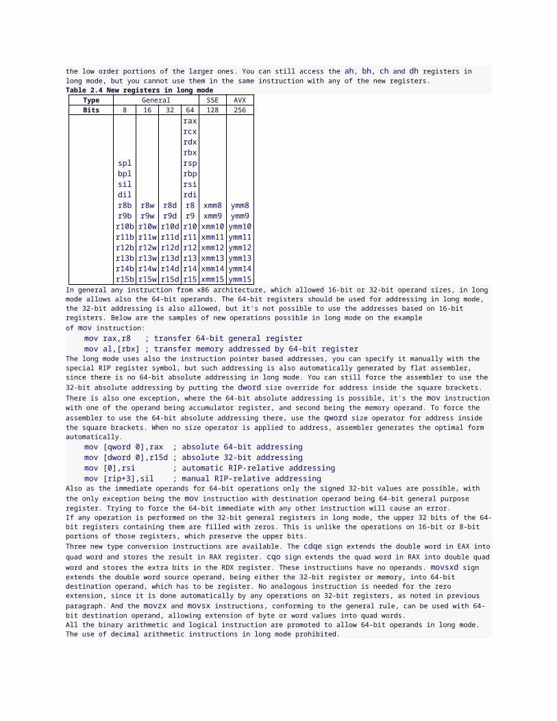
source, and the following ones being the second and third source. The mnemonic of FMA instruction is obtained by appending to vf prefix: first either m or nm to select whether result of multiplication should be taken as-is or negated, then either add or sub to select whether third value will be added to the product or substracted from the product, then either 132, 213 or 231 to select which source operands are multiplied and which one is added or substracted, and finally the type of data on which the instruction operates, either ps, pd, ss or sd. As it was with SSE instructions promoted to AVX, instructions operating on packed floating point values allow 128-bit or 256-bit syntax, in former all the operands are SSE registers, but the third one can also be a 128-bit memory, in latter the operands are AVX registers and the third one can also be a 256-bit memory. Instructions that compute just one floating point result need operands to be SSE registers, and the third operand can also be a memory, either 32-bit for single precision or 64-bit for double precision. vfmsub231ps ymm1,ymm2,ymm3 ; multiply and substract vfnmadd132sd xmm0,xmm5,[ebx] ; multiply, negate and addIn addition to the instructions created by the rule described above, there are families of instructions with mnemonics starting with eithervfmaddsub or vfmsubadd, followed by either 132, 213 or 231 and then either ps or pd (the operation must always be on packed values in this case). They add to the result of multiplication or substract from it depending on the position of value in packed data - instructions from thevfmaddsub group add when the position is odd and substract when the position is even, instructions from the vfmsubadd group add when the position is even and subtstract when the position is odd. The rules for operands are the same as for other FMA instructions.The FMA4 instructions are similar to FMA, but use syntax with four operands and thus allow destination to be different than all the sources. Their mnemonics are identical to FMA instructions with the 132, 213 or 231 cut out, as having separate destination operand makes such selection of operands superfluous. The multiplication is always performed on values from the first and second source, and then the value from third source is added or substracted. Either second or third source can be a memory operand, and the rules for the sizes of operands are the same as for FMA instructions. vfmaddpd ymm0,ymm1,[esi],ymm2 ; multiply and add vfmsubss xmm0,xmm1,xmm2,[ebx] ; multiply and substractThe F16C extension consists of two instructions, vcvtps2ph and vcvtph2ps, which convert floating point values between single precision and half precision (the 16-bit floating point format). vcvtps2ph takes three operands: destination, source, and rounding controls. The third operand is always an immediate, the source is either SSE or AVX register containing single precision values, and the destination is SSE register or memory, the size of memory is 64 bits when the source is SSE register and 128 bits when the source is AVX register. vcvtph2ps takes two operands, the destination that can be SSE or AVX register, and the source that is SSE register or memory with size of the half of destination operand's size.The AMD XOP extension introduces a number of new vector instructions with encoding and syntax analogous to AVX instructions. vfrczps,vfrczss, vfrczpd and vfrczsd extract fractional portions of single or double precision values, they all take two operands. The packed operations allow either SSE or AVX register as destination, for the other two it has to be SSE register. Source can be register of the same type as destination, or memory of appropriate size (256-bit for destination being AVX register, 128-bit for packed operation with destination being SSE register, 64-bit for operation on a solitary double precision value and 32-bit for operation on a solitary single precision value). vfrczps ymm0,[esi] ; load fractional partsvpcmov copies bits from either first or second source into destination depending on the values of corresponding bits in the fourth operand (the selector). If the bit in selector is set, the corresponding bit from first source is copied into the same position in destination, otherwise the bit from second source is copied. Either second source or selector can be memory location, 128-bit or 256-bit depending on whether SSE registers or AVX registers are specified as the other operands. vpcmov xmm0,xmm1,xmm2,[ebx] ; selector in memory vpcmov ymm0,ymm5,[esi],ymm2 ; source in memoryThe family of packed comparison instructions take four operands, the destination and first source being SSE register, second source being SSE register or 128-bit memory and the fourth operand being immediate value defining the type of comparison. The mnemonic or instruction is created by appending to vpcom prefix either b or ub to compare signed or unsigned bytes, w or uw to compare signed or unsigned words, d or ud to compare signed or unsigned double words, q or uq to compare signed or unsigned quad words. The respective values from the first and second source are compared and the corresponding data element in destination is set to either all ones or all zeros depending on the result of comparison. The fourth operand has to specify one of the eight comparison types (table 2.5). All these instructions have also variants with only three operands and the type of comparison encoded within the instruction name by inserting the comparison mnemonic after vpcom. vpcomb xmm0,xmm1,xmm2,4 ; test for equal bytes vpcomgew xmm0,xmm1,[ebx] ; compare signed wordsTable 2.5 XOP comparisons.
Code Mnemonic Description0 lt less than1 le less than or equal2 gt greater than3 ge greater than or equal4 eq equal5 neq not equal6 false false7 true true
vpermil2ps and vpermil2pd set the elements in destination register to zero or to a value selected from first or second source depending on the corresponding bit fields from the fourth operand (the selector) and the immediate value provided in fifth operand. Refer to the AMD manuals for the detailed explanation of the operation performed by these instructions. Each of the first four operands can be a register, and either second source or selector can be memory location, 128-bit or 256-bit depending on whether SSE registers or AVX registers are used for the other operands.
vpermil2ps ymm0,ymm3,ymm7,ymm2,0 ; permute from two sourcesvphaddbw adds pairs of adjacent signed bytes to form 16-bit values and stores them at the same positions in destination. vphaddubw does the same but treats the bytes as unsigned. vphaddbd and vphaddubd sum all bytes (either signed or unsigned) in each four-byte block to 32-bit results, vphaddbq and vphaddubq sum all bytes in each eight-byte block to 64-bit results, vphaddwd and vphadduwd add pairs of words to 32-bit results, vphaddwq and vphadduwq sum all words in each four-word block to 64-bit results, vphadddq and vphaddudq add pairs of double words to 64-bit results. vphsubbw substracts in each two-byte block the byte at higher position from the one at lower position, and stores the result as a signed 16-bit value at the corresponding position in destination, vphsubwd substracts in each two-word block the word at higher position from the one at lower position and makes signed 32-bit results, vphsubdq substract in each block of two double word the one at higher position from the one at lower position and makes signed 64-bit results. Each of these instructions takes two operands, the destination being SSE register, and the source being SSE register or 128-bit memory. vphadduwq xmm0,xmm1 ; sum quadruplets of wordsvpmacsww and vpmacssww multiply the corresponding signed 16-bit values from the first and second source and then add the products to the parallel values from the third source, then vpmacsww takes the lowest 16 bits of the result and vpmacssww saturates the result down to 16-bit value, and they store the final 16-bit results in the destination. vpmacsdd and vpmacssdd perform the analogous operation on 32-bit values.vpmacswd and vpmacsswd do the same calculation only on the low 16-bit values from each 32-bit block and form the 32-bit results. vpmacsdqland vpmacssdql perform such operation on the low 32-bit values from each 64-bit block and form the 64-bit results, while vpmacsdqh andvpmacssdqh do the same on the high 32-bit values from each 64-bit block, also forming the 64-bit results. vpmadcswd and vpmadcsswdmultiply the corresponding signed 16-bit value from the first and second source, then sum all the four products and add this sum to each 16-bit element from third source, storing the truncated or saturated result in destination. All these instructions take four operands, the second source can be 128-bit memory or SSE register, all the other operands have to be SSE registers. vpmacsdd xmm6,xmm1,[ebx],xmm6 ; accumulate productvpperm selects bytes from first and second source, optionally applies a separate transformation to each of them, and stores them in the destination. The bit fields in fourth operand (the selector) specify for each position in destination what byte from which source is taken and what operation is applied to it before it is stored there. Refer to the AMD manuals for the detailed information about these bit fields. This instruction takes four operands, either second source or selector can be a 128-bit memory (or they can be SSE registers both), all the other operands have to be SSE registers.vpshlb, vpshlw, vpshld and vpshlq shift logically bytes, words, double words or quad words respectively. The amount of bits to shift by is specified for each element separately by the signed byte placed at the corresponding position in the third operand. The source containing elements to shift is provided as second operand. Either second or third operand can be 128-bit memory (or they can be SSE registers both) and the other operands have to be SSE registers. vpshld xmm3,xmm1,[ebx] ; shift bytes from xmm1vpshab, vpshaw, vpshad and vpshaq arithmetically shift bytes, words, double words or quad words. These instructions follow the same rules as the logical shifts described above. vprotb, vprotw, vprotd and vprotq rotate bytes, word, double words or quad words. They follow the same rules as shifts, but additionally allow third operand to be immediate value, in which case the same amount of rotation is specified for all the elements in source. vprotb xmm0,[esi],3 ; rotate bytes to the leftThe MOVBE extension introduces just one new instruction, movbe, which swaps bytes in value from source before storing it in destination, so can be used to load and store big endian values. It takes two operands, either the destination or source should be a 16-bit, 32-bit or 64-bit memory (the last one being only allowed in long mode), and the other operand should be a general register of the same size.The BMI extension, consisting of two subsets - BMI1 and BMI2, introduces new instructions operating on general registers, which use the same encoding as AVX instructions and so allow the extended syntax. All these instructions use 32-bit operands, and in long mode they also allow the forms with 64-bit operands.andn calculates the bitwise AND of second source with the inverted bits of first source and stores the result in destination. The destination and the first source have to be general registers, the second source can be general register or memory. andn edx,eax,[ebx] ; bit-multiply inverted eax with memorybextr extracts from the first source the sequence of bits using an index and length specified by bit fields in the second source operand and stores it into destination. The lowest 8 bits of second source specify the position of bit sequence to extract and the next 8 bits of second source specify the length of sequence. The first source can be a general register or memory, the other two operands have to be general registers. bextr eax,[esi],ecx ; extract bit field from memoryblsi extracts the lowest set bit from the source, setting all the other bits in destination to zero. The destination must be a general register, the source can be general register or memory. blsi rax,r11 ; isolate the lowest set bitblsmsk sets all the bits in the destination up to the lowest set bit in the source, including this bit. blsr copies all the bits from the source to destination except for the lowest set bit, which is replaced by zero. These instructions follow the same rules for operands as blsi.tzcnt counts the number of trailing zero bits, that is the zero bits up to the lowest set bit of source value. This instruction is analogous to lzcntand follows the same rules for operands, so it also has a 16-bit version, unlike the other BMI instructions.bzhi is BMI2 instruction, which copies the bits from first source to destination, zeroing all the bits up from the position specified by second source. It follows the same rules for operands as bextr.pext uses a mask in second source operand to select bits from first operands and puts the selected bits as a continuous sequence into destination.pdep performs the reverse operation - it takes sequence of bits from the first source and puts
them consecutively at the positions where the bits in second source are set, setting all the other bits in destination to zero. These BMI2 instructions follow the same rules for operands as andn.mulx is a BMI2 instruction which performs an unsigned multiplication of value from EDX or RDX register (depending on the size of specified operands) by the value from third operand, and stores the low half of result in the second operand, and the high half of result in the first operand, and it does it without affecting the flags. The third operand can be general register or memory, and both the destination operands have to be general registers. mulx edx,eax,ecx ; multiply edx by ecx into edx:eaxshlx, shrx and sarx are BMI2 instructions, which perform logical or arithmetical shifts of value from first source by the amount specified by second source, and store the result in destination without affecting the flags. The have the same rules for operands as bzhi instruction.rorx is a BMI2 instruction which rotates right the value from source operand by the constant amount specified in third operand and stores the result in destination without affecting the flags. The destination operand has to be general register, the source operand can be general register or memory, and the third operand has to be an immediate value. rorx eax,edx,7 ; rotate without affecting flagsThe TBM is an extension designed by AMD to supplement the BMI set. The bextr instruction is extended with a new form, in which second source is a 32-bit immediate value. blsic is a new instruction which performs the same operation as blsi, but with the bits of result reversed. It uses the same rules for operands as blsi. blsfill is a new instruction, which takes the value from source, sets all the bits below the lowest set bit and store the result in destination, it also uses the same rules for operands as blsi.blci, blcic, blcs, blcmsk and blcfill are instructions analogous to blsi, blsic, blsr, blsmsk and blsfill respectively, but they perform the bit-inverted versions of the same operations. They follow the same rules for operands as the instructions they reflect.tzmsk finds the lowest set bit in value from source operand, sets all bits below it to 1 and all the rest of bits to zero, then writes the result to destination. t1mskc finds the least significant zero bit in the value from source operand, sets the bits below it to zero and all the other bits to 1, and writes the result to destination. These instructions have the same rules for operands as blsi.2.1.24 Other extensions of instruction setThere is a number of additional instruction set extensions recognized by flat assembler, and the general syntax of the instructions introduced by those extensions is provided here. For a detailed information on the operations performed by them, check out the manuals from Intel (for the VMX, SMX, XSAVE, RDRAND, FSGSBASE, INVPCID, HLE and RTM extensions) or AMD (for the SVM extension).The Virtual-Machine Extensions (VMX) provide a set of instructions for the management of virtual machines. The vmxon instruction, which enters the VMX operation, requires a single 64-bit memory operand, which should be a physical address of memory region, which the logical processor may use to support VMX operation. The vmxoff instruction, which leaves the VMX operation, has no operands. The vmlaunch and vmresume, which launch or resume the virtual machines, and vmcall, which allows guest software to call the VM monitor, use no operands either.The vmptrld loads the physical address of current Virtual Machine Control Structure (VMCS) from its memory operand, vmptrst stores the pointer to current VMCS into address specified by its memory operand, and vmclear sets the launch state of the VMCS referenced by its memory operand to clear. These three instruction all require single 64-bit memory operand.The vmread reads from VCMS a field specified by the source operand and stores it into the destination operand. The source operand should be a general purpose register, and the destination operand can be a register of memory. The vmwrite writes into a VMCS field specified by the destination operand the value provided by source operand. The source operand can be a general purpose register or memory, and the destination operand must be a register. The size of operands for those instructions should be 64-bit when in long mode, and 32-bit otherwise.The invept and invvpid invalidate the translation lookaside buffers (TLBs) and paging-structure caches, either derived from extended page tables (EPT), or based on the virtual processor identifier (VPID). These instructions require two operands, the first one being the general purpose register specifying the type of invalidation, and the second one being a 128-bit memory operand providing the invalidation descriptor. The first operand should be a 64-bit register when in long mode, and 32-bit register otherwise.The Safer Mode Extensions (SMX) provide the functionalities available throught the getsec instruction. This instruction takes no operands, and the function that is executed is determined by the contents of EAX register upon executing this instruction.The Secure Virtual Machine (SVM) is a variant of virtual machine extension used by AMD. The skinit instruction securely reinitializes the processor allowing the startup of trusted software, such as the virtual machine monitor (VMM). This instruction takes a single operand, which must be EAX, and provides a physical address of the secure loader block (SLB).The vmrun instruction is used to start a guest virtual machine, its only operand should be an accumulator register (AX, EAX or RAX, the last one available only in long mode) providing the physical address of the virtual machine control block (VMCB). The vmsave stores a subset of processor state into VMCB specified by its operand, and vmload loads the same subset of processor state from a specified VMCB. The same operand rules as for the vmrun apply to those two instructions.vmmcall allows the guest software to call the VMM. This instruction takes no operands.stgi set the global interrupt flag to 1, and clgi zeroes it. These instructions take no operands.invlpga invalidates the TLB mapping for a virtual page specified by the first operand (which has to be accumulator register) and address space identifier specified by the second operand (which must be ECX register).The XSAVE set of instructions allows to save and restore processor state components. xsave and xsaveopt store the components of processor state defined by bit mask in EDX and EAX registers into area defined by memory operand. xrstor restores from the area specified by memory operand the components of processor state defined by mask in EDX and EAX. The xsave64, xsaveopt64 and xrstor64 are 64-bit versions of these instructions, allowed only in long mode.
xgetbv read the contents of 64-bit XCR (extended control register) specified in ECX register into EDX and EAX registers. xsetbv writes the contents of EDX and EAX into the 64-bit XCR specified by ECX register. These instructions have no operands.The RDRAND extension introduces one new instruction, rdrand, which loads the hardware-generated random value into general register. It takes one operand, which can be 16-bit, 32-bit or 64-bit register (with the last one being allowed only in long mode).The FSGSBASE extension adds long mode instructions that allow to read and write the segment base registers for FS and GS segments. rdfsbaseand rdgsbase read the corresponding segment base registers into operand, while wrfsbase and wrgsbase write the value of operand into those register. All these instructions take one operand, which can be 32-bit or 64-bit general register.The INVPCID extension adds invpcid instruction, which invalidates mapping in the TLBs and paging caches based on the invalidation type specified in first operand and PCID invalidate descriptor specified in second operand. The first operands should be 32-bit general register when not in long mode, or 64-bit general register when in long mode. The second operand should be 128-bit memory location.The HLE and RTM extensions provide set of instructions for the transactional management. The xacquire and xrelease are new prefixes that can be used with some of the instructions to start or end lock elision on the memory address specified by prefixed instruction. The xbegininstruction starts the transactional execution, its operand is the address a fallback routine that gets executes in case of transaction abort, specified like the operand for near jump instruction. xend marks the end of transcational execution region, it takes no operands. xabort forces the transaction abort, it takes an 8-bit immediate value as its only operand, this value is passed in the highest bits of EAX to the fallback routine.xtest checks whether there is transactional execution in progress, this instruction takes no operands.2.2 Control directivesThis section describes the directives that control the assembly process, they are processed during the assembly and may cause some blocks of instructions to be assembled differently or not assembled at all.2.2.1 Numerical constantsThe = directive allows to define the numerical constant. It should be preceded by the name for the constant and followed by the numerical expression providing the value. The value of such constants can be a number or an address, but - unlike labels - the numerical constants are not allowed to hold the register-based addresses. Besides this difference, in their basic variant numerical constants behave very much like labels and you can even forward-reference them (access their values before they actually get defined).There is, however, a second variant of numerical constants, which is recognized by assembler when you try to define the constant of name, under which there already was a numerical constant defined. In such case assembler treats that constant as an assembly-time variable and allows it to be assigned with new value, but forbids forward-referencing it (for obvious reasons). Let's see both the variant of numerical constants in one example: dd sum x = 1 x = x+2 sum = xHere the x is an assembly-time variable, and every time it is accessed, the value that was assigned to it the most recently is used. Thus if we tried to access the x before it gets defined the first time, like if we wrote dd x in place of the dd sum instruction, it would cause an error. And when it is re-defined with the x = x+2 directive, the previous value of x is used to calculate the new one. So when the sum constant gets defined, the x has value of 3, and this value is assigned to the sum. Since this one is defined only once in source, it is the standard numerical constant, and can be forward-referenced. So the dd sum is assembled as dd 3. To read more about how the assembler is able to resolve this, see section 2.2.6.The value of numerical constant can be preceded by size operator, which can ensure that the value will fit in the range for the specified size, and can affect also how some of the calculations inside the numerical expression are performed. This example: c8 = byte -1 c32 = dword -1defines two different constants, the first one fits in 8 bits, the second one fits in 32 bits.When you need to define constant with the value of address, which may be register-based (and thus you cannot employ numerical constant for this purpose), you can use the extended syntax of label directive (already described in section 1.2.3), like: label myaddr at ebp+4which declares label placed at ebp+4 address. However remember that labels, unlike numerical constants, cannot become assembly-time variables.2.2.2 Conditional assemblyif directive causes come block of instructions to be assembled only under certain condition. It should be followed by logical expression specifying the condition, instructions in next lines will be assembled only when this condition is met, otherwise they will be skipped. The optional else ifdirective followed with logical expression specifying additional condition begins the next block of instructions that will be assembled if previous conditions were not met, and the additional condition is met. The optional else directive begins the block of instructions that will be assembled if all the conditions were not met. The end if directive ends the last block of instructions.You should note that if directive is processed at assembly stage and therefore it doesn't affect any preprocessor directives, like the definitions of symbolic constants and macroinstructions - when the assembler recognizes the if directive, all the preprocessing has been already finished.The logical expression consist of logical values and logical operators. The logical operators are ~ for logical negation, & for logical and, | for logical or. The negation has the highest priority. Logical value can be a numerical expression, it will be
false if it is equal to zero, otherwise it will be true. Two numerical expression can be compared using one of the following operators to make the logical value: = (equal), < (less), > (greater), <=(less or equal), >= (greater or equal), <> (not equal).The used operator followed by a symbol name, is the logical value that checks whether the given symbol is used somewhere (it returns correct result even if symbol is used only after this check). The defined operator can be followed by any expression, usually just by a single symbol name; it checks whether the given expression contains only symbols that are defined in the source and accessible from the current position.With relativeto operator it is possible to check whether values of two expressions differ only by constant amount. The valid syntax is a numerical expression followed by relativeto and then another expression (possibly register-based). Labels that have no simple numerical value can be tested this way to determine what kind of operations may be possible with them.The following simple example uses the count constant that should be defined somewhere in source: if count>0 mov cx,count rep movsb end ifThese two assembly instructions will be assembled only if the count constant is greater than 0. The next sample shows more complex conditional structure: if count & ~ count mod 4 mov cx,count/4 rep movsd else if count>4 mov cx,count/4 rep movsd mov cx,count mod 4 rep movsb else mov cx,count rep movsb end ifThe first block of instructions gets assembled when the count is non zero and divisible by four, if this condition is not met, the second logical expression, which follows the else if, is evaluated and if it's true, the second block of instructions get assembled, otherwise the last block of instructions, which follows the line containing only else, is assembled.There are also operators that allow comparison of values being any chains of symbols. The eq compares whether two such values are exactly the same. The in operator checks whether given value is a member of the list of values following this operator, the list should be enclosed between <and > characters, its members should be separated with commas. The symbols are considered the same when they have the same meaning for the assembler - for example pword and fword for assembler are the same and thus are not distinguished by the above operators. In the same way16 eq 10h is the true condition, however 16 eq 10+4 is not.The eqtype operator checks whether the two compared values have the same structure, and whether the structural elements are of the same type. The distinguished types include numerical expressions, individual quoted strings, floating point numbers, address expressions (the expressions enclosed in square brackets or preceded by ptr operator), instruction mnemonics, registers, size operators, jump type and code type operators. And each of the special characters that act as a separators, like comma or colon, is the separate type itself. For example, two values, each one consisting of register name followed by comma and numerical expression, will be regarded as of the same type, no matter what kind of register and how complicated numerical expression is used; with exception for the quoted strings and floating point values, which are the special kinds of numerical expressions and are treated as different types. Thus eax,16 eqtype fs,3+7 condition is true, but eax,16 eqtype eax,1.6 is false.2.2.3 Repeating blocks of instructionstimes directive repeats one instruction specified number of times. It should be followed by numerical expression specifying number of repeats and the instruction to repeat (optionally colon can be used to separate number and instruction). When special symbol % is used inside the instruction, it is equal to the number of current repeat. For example times 5 db % will define five bytes with values 1, 2, 3, 4, 5. Recursive use of timesdirective is also allowed, so times 3 times % db % will define six bytes with values 1, 1, 2, 1, 2, 3.repeat directive repeats the whole block of instructions. It should be followed by numerical expression specifying number of repeats. Instructions to repeat are expected in next lines, ended with the end repeat directive, for example: repeat 8 mov byte [bx],% inc bx end repeatThe generated code will store byte values from one to eight in the memory addressed by BX register.Number of repeats can be zero, in that case the instructions are not assembled at all.The break directive allows to stop repeating earlier and continue assembly from the first line after the end repeat. Combined with the ifdirective it allows to stop repeating under some special condition, like: s = x/2 repeat 100 if x/s = s break end if
s = (s+x/s)/2 end repeatThe while directive repeats the block of instructions as long as the condition specified by the logical expression following it is true. The block of instructions to be repeated should end with the end while directive. Before each repetition the logical expression is evaluated and when its value is false, the assembly is continued starting from the first line after the end while. Also in this case the % symbol holds the number of current repeat. The break directive can be used to stop this kind of loop in the same way as with repeat directive. The previous sample can be rewritten to use the while instead of repeat this way: s = x/2 while x/s <> s s = (s+x/s)/2 if % = 100 break end if end whileThe blocks defined with if, repeat and while can be nested in any order, however they should be closed in the same order in which they were started. The break directive always stops processing the block that was started last with either the repeat or while directive.2.2.4 Addressing spacesorg directive sets address at which the following code is expected to appear in memory. It should be followed by numerical expression specifying the address. This directive begins the new addressing space, the following code itself is not moved in any way, but all the labels defined within it and the value of $ symbol are affected as if it was put at the given address. However it's the responsibility of programmer to put the code at correct address at run-time.The load directive allows to define constant with a binary value loaded from the already assembled code. This directive should be followed by the name of the constant, then optionally size operator, then from operator and a numerical expression specifying a valid address in current addressing space. The size operator has unusual meaning in this case - it states how many bytes (up to 8) have to be loaded to form the binary value of constant. If no size operator is specified, one byte is loaded (thus value is in range from 0 to 255). The loaded data cannot exceed current offset.The store directive can modify the already generated code by replacing some of the previously generated data with the value defined by given numerical expression, which follows. The expression can be preceded by the optional size operator to specify how large value the expression defines, and therefore how much bytes will be stored, if there is no size operator, the size of one byte is assumed. Then the at operator and the numerical expression defining the valid address in current addressing code space, at which the given value have to be stored should follow. This is a directive for advanced appliances and should be used carefully.Both load and store directives in their basic variant (defined above) are limited to operate on places in current addressing space. The $$ symbol is always equal to the base address of current addressing space, and the $ symbol is the address of current position in that addressing space, therefore these two values define limits of the area, where load and store can operate.Combining the load and store directives allows to do things like encoding some of the already generated code. For example to encode the whole code generated in current addressing space you can use such block of directives: repeat $-$$ load a byte from $$+%-1 store byte a xor c at $$+%-1 end repeatand each byte of code will be xored with the value defined by c constant.virtual defines virtual data at specified address. This data will not be included in the output file, but labels defined there can be used in other parts of source. This directive can be followed by at operator and the numerical expression specifying the address for virtual data, otherwise is uses current address, the same as virtual at $. Instructions defining data are expected in next lines, ended with end virtual directive. The block of virtual instructions itself is an independent addressing space, after it's ended, the context of previous addressing space is restored.The virtual directive can be used to create union of some variables, for example: GDTR dp ? virtual at GDTR GDT_limit dw ? GDT_address dd ? end virtualIt defines two labels for parts of the 48-bit variable at GDTR address.It can be also used to define labels for some structures addressed by a register, for example: virtual at bx LDT_limit dw ? LDT_address dd ? end virtualWith such definition instruction mov ax,[LDT_limit] will be assembled to the same instruction as mov ax,[bx].Declaring defined data values or instructions inside the virtual block could also be useful, because the load directive may be used to load the values from the virtually generated code into a constants. This directive in its basic version should be used after the code it loads but before the virtual block ends, because it can only load the values from the same addressing space. For example: virtual at 0
xor eax,eax and edx,eax load zeroq dword from 0 end virtualThe above piece of code will define the zeroq constant containing four bytes of the machine code of the instructions defined inside the virtual block. This method can be also used to load some binary value from external file. For example this code: virtual at 0 file 'a.txt':10h,1 load char from 0 end virtualloads the single byte from offset 10h in file a.txt into the char constant.Any of the section directives described in 2.4 also begins a new addressing space.It is possible to declare a special kind of label that marks the current addressing space, by appending a double colon instead of a single one after a label name. This symbol cannot then be used in numerical expressions, the only place where it is allowed to use it is the extended syntax of loadand store directives. It is possible to make these directives operate on a different addressing space than the current one, by specifying address with the two components: first the name of a special label that marks the addressing space, followed by the colon character and a numerical expression defining a valid address inside that addressing space. In the following example this extended syntax is used to load the value from a block after it has been closed: virtual at 0 hex_digits:: db '0123456789ABCDEF' end virtual load a byte from hex_digits:10This way it is possible to operate on values inside any code block, including all the ones defined with virtual. However it is not allowed to specify addressing space that has not been assembled yet, just as it is not allowed to specify an address in the current addressing space that exceeds the current offset. The addresses in any other addressing space are also limited by the boundaries of the block.2.2.5 Other directivesalign directive aligns code or data to the specified boundary. It should be followed by a numerical expression specifying the number of bytes, to the multiply of which the current address has to be aligned. The boundary value has to be the power of two.The align directive fills the bytes that had to be skipped to perform the alignment with the nop instructions and at the same time marks this area as uninitialized data, so if it is placed among other uninitialized data that wouldn't take space in the output file, the alignment bytes will act the same way. If you need to fill the alignment area with some other values, you can combine align with virtual to get the size of alignment needed and then create the alignment yourself, like: virtual align 16 a = $ - $$ end virtual db a dup 0The a constant is defined to be the difference between address after alignment and address of the virtual block (see previous section), so it is equal to the size of needed alignment space.display directive displays the message at the assembly time. It should be followed by the quoted strings or byte values, separated with commas. It can be used to display values of some constants, for example: bits = 16 display 'Current offset is 0x' repeat bits/4 d = '0' + $ shr (bits-%*4) and 0Fh if d > '9' d = d + 'A'-'9'-1 end if display d end repeat display 13,10This block of directives calculates the four hexadecimal digits of 16-bit value and converts them into characters for displaying. Note that this will not work if the adresses in current addressing space are relocatable (as it might happen with PE or object output formats), since only absolute values can be used this way. The absolute value may be obtained by calculating the relative address, like $-$$, or rva $ in case of PE format.The err directive immediately terminates the assembly process when it is encountered by assembler.The assert directive tests whether the logical expression that follows it is true, and if not, it signalizes the error.2.2.6 Multiple passesBecause the assembler allows to reference some of the labels or constants before they get actually defined, it has to predict the values of such labels and if there is even a suspicion that prediction failed in at least one case, it does one more pass, assembling the whole source, this time doing better prediction based on the values the labels got in the previous pass.The changing values of labels can cause some instructions to have encodings of different length, and this can cause the change in values of labels again. And since the labels and constants can also be used inside the expressions that affect the
behavior of control directives, the whole block of source can be processed completely differently during the new pass. Thus the assembler does more and more passes, each time trying to do better predictions to approach the final solution, when all the values get predicted correctly. It uses various method for predicting the values, which has been chosen to allow finding in a few passes the solution of possibly smallest length for the most of the programs.Some of the errors, like the values not fitting in required boundaries, are not signaled during those intermediate passes, since it may happen that when some of the values are predicted better, these errors will disappear. However if assembler meets some illegal syntax construction or unknown instruction, it always stops immediately. Also defining some label more than once causes such error, because it makes the predictions groundless.Only the messages created with the display directive during the last performed pass get actually displayed. In case when the assembly has been stopped due to an error, these messages may reflect the predicted values that are not yet resolved correctly.The solution may sometimes not exist and in such cases the assembler will never manage to make correct predictions - for this reason there is a limit for a number of passes, and when assembler reaches this limit, it stops and displays the message that it is not able to generate the correct output. Consider the following example: if ~ defined alpha alpha: end ifThe defined operator gives the true value when the expression following it could be calculated in this place, what in this case means that thealpha label is defined somewhere. But the above block causes this label to be defined only when the value given by defined operator is false, what leads to an antynomy and makes it impossible to resolve such code. When processing the if directive assembler has to predict whether thealpha label will be defined somewhere (it wouldn't have to predict only if the label was already defined earlier in this pass), and whatever the prediction is, the opposite always happens. Thus the assembly will fail, unless the alpha label is defined somewhere in source preceding the above block of instructions - in such case, as it was already noted, the prediction is not needed and the block will just get skipped.The above sample might have been written as a try to define the label only when it was not yet defined. It fails, because the defined operator does check whether the label is defined anywhere, and this includes the definition inside this conditionally processed block. However adding some additional condition may make it possible to get it resolved: if ~ defined alpha | defined @f alpha: @@: end ifThe @f is always the same label as the nearest @@ symbol in the source following it, so the above sample would mean the same if any unique name was used instead of the anonymous label. When alpha is not defined in any other place in source, the only possible solution is when this block gets defined, and this time this doesn't lead to the antynomy, because of the anonymous label which makes this block self-establishing. To better understand this, look at the blocks that has nothing more than this self-establishing: if defined @f @@: end ifThis is an example of source that may have more than one solution, as both cases when this block gets processed or not are equally correct. Which one of those two solutions we get depends on the algorithm on the assembler, in case of flat assembler - on the algorithm of predictions. Back to the previous sample, when alpha is not defined anywhere else, the condition for if block cannot be false, so we are left with only one possible solution, and we can hope the assembler will arrive at it. On the other hand, when alpha is defined in some other place, we've got two possible solutions again, but one of them causes alpha to be defined twice, and such an error causes assembler to abort the assembly immediately, as this is the kind of error that deeply disturbs the process of resolving. So we can get such source either correctly resolved or causing an error, and what we get may depend on the internal choices made by the assembler.However there are some facts about such choices that are certain. When assembler has to check whether the given symbol is defined and it was already defined in the current pass, no prediction is needed - it was already noted above. And when the given symbol has been defined never before, including all the already finished passes, the assembler predicts it to be not defined. Knowing this, we can expect that the simple self-establishing block shown above will not be assembled at all and that the previous sample will resolve correctly when alpha is defined somewhere before our conditional block, while it will itself define alpha when it's not already defined earlier, thus potentially causing the error because of double definition if the alpha is also defined somewhere later.The used operator may be expected to behave in a similar manner in analogous cases, however any other kinds of predictions may not be so simple and you should never rely on them this way.The err directive, usually used to stop the assembly when some condition is met, stops the assembly immediately, regardless of whether the current pass is final or intermediate. So even when the condition that caused this directive to be interpreted is temporary, and would eventually disappear in the later passes, the assembly is stopped anyway.The assert directive signalizes the error only if its expression is false after all the symbols have been resolved. You can use assert 0 in place of err when you do not want to have assembly stopped during the intermediate passes.2.3 Preprocessor directivesAll preprocessor directives are processed before the main assembly process, and therefore are not affected by the control directives. At this time also all comments are stripped out.2.3.1 Including source filesinclude directive includes the specified source file at the position where it is used. It should be followed by the quoted name of file that should be included, for example: include 'macros.inc'The whole included file is preprocessed before preprocessing the lines next to the line containing the include directive. There are no limits to the number of included files as long as they fit in memory.
The quoted path can contain environment variables enclosed within % characters, they will be replaced with their values inside the path, both the \and / characters are allowed as a path separators. The file is first searched for in the directory containing file which included it and when it is not found there, the search is continued in the directories specified in the environment variable called INCLUDE (the multiple paths separated with semicolons can be defined there, they will be searched in the same order as specified). If file was not found in any of these places, preprocessor looks for it in the directory containing the main source file (the one specified in command line). These rules concern also paths given with thefile directive.2.3.2 Symbolic constantsThe symbolic constants are different from the numerical constants, before the assembly process they are replaced with their values everywhere in source lines after their definitions, and anything can become their values.The definition of symbolic constant consists of name of the constant followed by the equ directive. Everything that follows this directive will become the value of constant. If the value of symbolic constant contains other symbolic constants, they are replaced with their values before assigning this value to the new constant. For example: d equ dword NULL equ d 0 d equ edxAfter these three definitions the value of NULL constant is dword 0 and the value of d is edx. So, for example, push NULL will be assembled as push dword 0 and push d will be assembled as push edx. And if then the following line was put: d equ d,eaxthe d constant would get the new value of edx,eax. This way the growing lists of symbols can be defined.restore directive allows to get back previous value of redefined symbolic constant. It should be followed by one more names of symbolic constants, separated with commas. So restore d after the above definitions will give d constant back the value edx, the second one will restore it to value dword, and one more will revert d to original meaning as if no such constant was defined. If there was no constant defined of given name, restore will not cause an error, it will be just ignored.Symbolic constant can be used to adjust the syntax of assembler to personal preferences. For example the following set of definitions provides the handy shortcuts for all the size operators: b equ byte w equ word d equ dword p equ pword f equ fword q equ qword t equ tword x equ dqword y equ qqwordBecause symbolic constant may also have an empty value, it can be used to allow the syntax with offset word before any address value: offset equAfter this definition mov ax,offset char will be valid construction for copying the offset of char variable into ax register, because offset is replaced with an empty value, and therefore ignored.The define directive followed by the name of constant and then the value, is the alternative way of defining symbolic constant. The only difference between define and equ is that define assigns the value as it is, it does not replace the symbolic constants with their values inside it.Symbolic constants can also be defined with the fix directive, which has the same syntax as equ, but defines constants of high priority - they are replaced with their symbolic values even before processing the preprocessor directives and macroinstructions, the only exception is fix directive itself, which has the highest possible priority, so it allows redefinition of constants defined this way.The fix directive can be used for syntax adjustments related to directives of preprocessor, what cannot be done with equ directive. For example: incl fix includedefines a short name for include directive, while the similar definition done with equ directive wouldn't give such result, as standard symbolic constants are replaced with their values after searching the line for preprocessor directives.2.3.3 Macroinstructionsmacro directive allows you to define your own complex instructions, called macroinstructions, using which can greatly simplify the process of programming. In its simplest form it's similar to symbolic constant definition. For example the following definition defines a shortcut for the test al,0xFF instruction: macro tst {test al,0xFF}After the macro directive there is a name of macroinstruction and then its contents enclosed between the { and } characters. You can use tstinstruction anywhere after this definition and it will be assembled as test al,0xFF. Defining symbolic constant tst of that value would give the similar result, but the difference is that the name of macroinstruction is recognized only as an instruction mnemonic. Also, macroinstructions are replaced with corresponding code even before the symbolic constants are replaced with their values. So if you define macroinstruction and symbolic constant of the same name, and use this name as an instruction mnemonic, it will be replaced with the contents of macroinstruction, but it will be replaced with value if symbolic constant if used somewhere inside the operands.The definition of macroinstruction can consist of many lines, because { and } characters don't have to be in the same line as macro directive. For example: macro stos0
{ xor al,al stosb }The macroinstruction stos0 will be replaced with these two assembly instructions anywhere it's used.Like instructions which needs some number of operands, the macroinstruction can be defined to need some number of arguments separated with commas. The names of needed argument should follow the name of macroinstruction in the line of macro directive and should be separated with commas if there is more than one. Anywhere one of these names occurs in the contents of macroinstruction, it will be replaced with corresponding value, provided when the macroinstruction is used. Here is an example of a macroinstruction that will do data alignment for binary output format: macro align value { rb (value-1)-($+value-1) mod value }When the align 4 instruction is found after this macroinstruction is defined, it will be replaced with contents of this macroinstruction, and thevalue will there become 4, so the result will be rb (4-1)-($+4-1) mod 4.If a macroinstruction is defined that uses an instruction with the same name inside its definition, the previous meaning of this name is used. Useful redefinition of macroinstructions can be done in that way, for example: macro mov op1,op2 { if op1 in <ds,es,fs,gs,ss> & op2 in <cs,ds,es,fs,gs,ss> push op2 pop op1 else mov op1,op2 end if }This macroinstruction extends the syntax of mov instruction, allowing both operands to be segment registers. For example mov ds,es will be assembled as push es and pop ds. In all other cases the standard mov instruction will be used. The syntax of this mov can be extended further by defining next macroinstruction of that name, which will use the previous macroinstruction: macro mov op1,op2,op3 { if op3 eq mov op1,op2 else mov op1,op2 mov op2,op3 end if }It allows mov instruction to have three operands, but it can still have two operands only, because when macroinstruction is given less arguments than it needs, the rest of arguments will have empty values. When three operands are given, this macroinstruction will become two macroinstructions of the previous definition, so mov es,ds,dx will be assembled as push ds, pop es and mov ds,dx.By placing the * after the name of argument you can mark the argument as required - preprocessor will not allow it to have an empty value. For example the above macroinstruction could be declared as macro mov op1*,op2*,op3 to make sure that first two arguments will always have to be given some non empty values.Alternatively, you can provide the default value for argument, by placing the = followed by value after the name of argument. Then if the argument has an empty value provided, the default value will be used instead.When it's needed to provide macroinstruction with argument that contains some commas, such argument should be enclosed between < and >characters. If it contains more than one < character, the same number of > should be used to tell that the value of argument ends.purge directive allows removing the last definition of specified macroinstruction. It should be followed by one or more names of macroinstructions, separated with commas. If such macroinstruction has not been defined, you will not get any error. For example after having the syntax of mov extended with the macroinstructions defined above, you can disable syntax with three operands back by using purge mov directive. Next purge mov will disable also syntax for two operands being segment registers, and all the next such directives will do nothing.If after the macro directive you enclose some group of arguments' names in square brackets, it will allow giving more values for this group of arguments when using that macroinstruction. Any more argument given after the last argument of such group will begin the new group and will become the first argument of it. That's why after closing the square bracket no more argument names can follow. The contents of macroinstruction will be processed for each such group of arguments separately. The simplest example is to enclose one argument name in square brackets: macro stoschar [char] { mov al,char stosb }This macroinstruction accepts unlimited number of arguments, and each one will be processed into these two instructions separately. For examplestoschar 1,2,3 will be assembled as the following instructions: mov al,1 stosb
mov al,2 stosb mov al,3 stosbThere are some special directives available only inside the definitions of macroinstructions. local directive defines local names, which will be replaced with unique values each time the macroinstruction is used. It should be followed by names separated with commas. If the name given as parameter to local directive begins with a dot or two dots, the unique labels generated by each evaluation of macroinstruction will have the same properties. This directive is usually needed for the constants or labels that macroinstruction defines and uses internally. For example: macro movstr { local move move: lodsb stosb test al,al jnz move }Each time this macroinstruction is used, move will become other unique name in its instructions, so you will not get an error you normally get when some label is defined more than once.forward, reverse and common directives divide macroinstruction into blocks, each one processed after the processing of previous is finished. They differ in behavior only if macroinstruction allows multiple groups of arguments. Block of instructions that follows forward directive is processed for each group of arguments, from first to last - exactly like the default block (not preceded by any of these directives). Block that follows reverse directive is processed for each group of argument in reverse order - from last to first. Block that follows common directive is processed only once, commonly for all groups of arguments. Local name defined in one of the blocks is available in all the following blocks when processing the same group of arguments as when it was defined, and when it is defined in common block it is available in all the following blocks not depending on which group of arguments is processed.Here is an example of macroinstruction that will create the table of addresses to strings followed by these strings: macro strtbl name,[string] { common label name dword forward local label dd label forward label db string,0 }First argument given to this macroinstruction will become the label for table of addresses, next arguments should be the strings. First block is processed only once and defines the label, second block for each string declares its local name and defines the table entry holding the address to that string. Third block defines the data of each string with the corresponding label.The directive starting the block in macroinstruction can be followed by the first instruction of this block in the same line, like in the following example: macro stdcall proc,[arg] { reverse push arg common call proc }This macroinstruction can be used for calling the procedures using STDCALL convention, which has all the arguments pushed on stack in the reverse order. For example stdcall foo,1,2,3 will be assembled as: push 3 push 2 push 1 call fooIf some name inside macroinstruction has multiple values (it is either one of the arguments enclosed in square brackets or local name defined in the block following forward or reverse directive) and is used in block following the common directive, it will be replaced with all of its values, separated with commas. For example the following macroinstruction will pass all of the additional arguments to the previously defined stdcallmacroinstruction: macro invoke proc,[arg] { common stdcall [proc],arg }It can be used to call indirectly (by the pointer stored in memory) the procedure using STDCALL convention.Inside macroinstruction also special operator # can be used. This operator causes two names to be concatenated into one name. It can be useful, because it's done after the arguments and local names are replaced with their values. The following macroinstruction will generate the conditional jump according to the cond argument: macro jif op1,cond,op2,label {
cmp op1,op2 j#cond label }For example jif ax,ae,10h,exit will be assembled as cmp ax,10h and jae exit instructions.The # operator can be also used to concatenate two quoted strings into one. Also conversion of name into a quoted string is possible, with the `operator, which likewise can be used inside the macroinstruction. It converts the name that follows it into a quoted string - but note, that when it is followed by a macro argument which is being replaced with value containing more than one symbol, only the first of them will be converted, as the ` operator converts only one symbol that immediately follows it. Here's an example of utilizing those two features: macro label name { label name if ~ used name display `name # " is defined but not used.",13,10 end if }When label defined with such macro is not used in the source, macro will warn you with the message, informing to which label it applies.To make macroinstruction behaving differently when some of the arguments are of some special type, for example a quoted strings, you can useeqtype comparision operator. Here's an example of utilizing it to distinguish a quoted string from an other argument: macro message arg { if arg eqtype "" local str jmp @f str db arg,0Dh,0Ah,24h @@: mov dx,str else mov dx,arg end if mov ah,9 int 21h }The above macro is designed for displaying messages in DOS programs. When the argument of this macro is some number, label, or variable, the string from that address is displayed, but when the argument is a quoted string, the created code will display that string followed by the carriage return and line feed.It is also possible to put a declaration of macroinstruction inside another macroinstruction, so one macro can define another, but there is a problem with such definitions caused by the fact, that } character cannot occur inside the macroinstruction, as it always means the end of definition. To overcome this problem, the escaping of symbols inside macroinstruction can be used. This is done by placing one or more backslashes in front of any other symbol (even the special character). Preprocessor sees such sequence as a single symbol, but each time it meets such symbol during the macroinstruction processing, it cuts the backslash character from the front of it. For example \} is treated as single symbol, but during processing of the macroinstruction it becomes the } symbol. This allows to put one definition of macroinstruction inside another: macro ext instr { macro instr op1,op2,op3 \{ if op3 eq instr op1,op2 else instr op1,op2 instr op2,op3 end if \} }
ext add ext subThe macro ext is defined correctly, but when it is used, the \{ and \} become the { and } symbols. So when the ext add is processed, the contents of macro becomes valid definition of a macroinstruction and this way theadd macro becomes defined. In the same wayext sub defines thesub macro. The use of \{ symbol wasn't really necessary here, but it's done this way to make the definition more clear.If some directives specific to macroinstructions, like local or common are needed inside some macro embedded this way, they can be escaped in the same way. Escaping the symbol with more than one backslash is also allowed, which allows multiple levels of nesting the macroinstruction definitions.
The another technique for defining one macroinstruction by another is to use the fix directive, which becomes useful when some macroinstruction only begins the definition of another one, without closing it. For example: macro tmacro [params] { common macro params { }
MACRO fix tmacro ENDM fix }defines an alternative syntax for defining macroinstructions, which looks like: MACRO stoschar char mov al,char stosb ENDMNote that symbol that has such customized definition must be defined with fix directive, because only the prioritized symbolic constants are processed before the preprocessor looks for the } character while defining the macro. This might be a problem if one needed to perform some additional tasks one the end of such definition, but there is one more feature which helps in such cases. Namely it is possible to put any directive, instruction or macroinstruction just after the } character that ends the macroinstruction and it will be processed in the same way as if it was put in the next line.The "postpone" directive can be used to define a special type of macroinstruction that has no name or arguments and will get automatically called when the preprocessor reaches the end of source: postpone { code_size = $ }It is a very simplified kind of macroinstruction and it simply delegates a block of instructions to be put at the end.2.3.4 Structuresstruc directive is a special variant of macro directive that is used to define data structures. Macroinstruction defined using the struc directive must be preceded by a label (like the data definition directive) when it's used. This label will be also attached at the beginning of every name starting with dot in the contents of macroinstruction. The macroinstruction defined using the struc directive can have the same name as some other macroinstruction defined using the macro directive, structure macroinstruction will not prevent the standard macroinstruction from being processed when there is no label before it and vice versa. All the rules and features concerning standard macroinstructions apply to structure macroinstructions.Here is the sample of structure macroinstruction: struc point x,y { .x dw x .y dw y }For example my point 7,11 will define structure labeled my, consisting of two variables: my.x with value 7 and my.y with value 11.If somewhere inside the definition of structure the name consisting of a single dot it found, it is replaced by the name of the label for the given instance of structure and this label will not be defined automatically in such case, allowing to completely customize the definition. The following example utilizes this feature to extend the data definition directive db with ability to calculate the size of defined data: struc db [data] { common . db data .size = $ - . }With such definition msg db 'Hello!',13,10 will define also msg.size constant, equal to the size of defined data in bytes.Defining data structures addressed by registers or absolute values should be done using the virtual directive with structure macroinstruction (see2.2.4).restruc directive removes the last definition of the structure, just like purge does with macroinstructions and restore with symbolic constants. It also has the same syntax - should be followed by one or more names of structure macroinstructions, separated with commas.2.3.5 Repeating macroinstructionsThe rept directive is a special kind of macroinstruction, which makes given amount of duplicates of the block enclosed with braces. The basic syntax is rept directive followed by number. and then block of source enclosed between the { and } characters. The simplest example: rept 5 { in al,dx }will make five duplicates of the in al,dx line. The block of instructions is defined in the same way as for the standard macroinstruction and any special operators and directives which can be used only inside macroinstructions are also allowed here. When the given count is zero, the block is simply skipped, as if you defined macroinstruction but never used it. The number of repetitions can be followed by the name of counter symbol, which will get replaced symbolically with the number of duplicate currently generated. So this:
rept 3 counter { byte#counter db counter }will generate lines: byte1 db 1 byte2 db 2 byte3 db 3The repetition mechanism applied to rept blocks is the same as the one used to process multiple groups of arguments for macroinstructions, so directives like forward, common and reverse can be used in their usual meaning. Thus such macroinstruction: rept 7 num { reverse display `num }will display digits from 7 to 1 as text. The local directive behaves in the same way as inside macroinstruction with multiple groups of arguments, so: rept 21 { local label label: loop label }will generate unique label for each duplicate.The counter symbol by default counts from 1, but you can declare different base value by placing the number preceded by colon immediately after the name of counter. For example: rept 8 n:0 { pxor xmm#n,xmm#n }will generate code which will clear the contents of eight SSE registers. You can define multiple counters separated with commas, and each one can have different base.The number of repetitions and the base values for counters can be specified using the numerical expressions with operator rules identical as in the case of assembler. However each value used in such expression must either be a directly specified number, or a symbolic constant with value also being an expression that can be calculated by preprocessor (in such case the value of expression associated with symbolic constant is calculated first, and then substituted into the outer expression in place of that constant). If you need repetitions based on values that can only be calculated at assembly time, use one of the code repeating directives that are processed by assembler, see section 2.2.3.The irp directive iterates the single argument through the given list of parameters. The syntax is irp followed by the argument name, then the comma and then the list of parameters. The parameters are specified in the same way like in the invocation of standard macroinstruction, so they have to be separated with commas and each one can be enclosed with the < and > characters. Also the name of argument may be followed by *to mark that it cannot get an empty value. Such block: irp value, 2,3,5 { db value }will generate lines: db 2 db 3 db 5The irps directive iterates through the given list of symbols, it should be followed by the argument name, then the comma and then the sequence of any symbols. Each symbol in this sequence, no matter whether it is the name symbol, symbol character or quoted string, becomes an argument value for one iteration. If there are no symbols following the comma, no iteration is done at all. This example: irps reg, al bx ecx { xor reg,reg }will generate lines: xor al,al xor bx,bx xor ecx,ecxThe irpv directive iterates through all of the values that were assigned to the given symbolic variable. It should be followed by the argument name and the name of symbolic variable, separated with comma. When the symbolic variable is treated with restore directive to remove its latest value, that value is removed from the list of values accessed by irpv. But any modifications made to that list during the iterations performed by irpv (by either defining a new value for symbolic variable, or destroying the value with restore directive) do not affect the operation performed by this directive - the list that gets iterated reflects the state of symbolic variable at the time when irpv directive was encountered. For example this snippet restores a symbolic variable called d to its initial state, before any values were assigned to it: irpv value, d { restore d }It simply generates as many copies of restore directive, as many values there are to remove.The blocks defined by the irp, irps and irpv directives are also processed in the same way as any macroinstructions, so operators and directives specific to macroinstructions may be freely used also in this case.2.3.6 Conditional preprocessingmatch directive causes some block of source to be preprocessed and passed to assembler only when the given sequence of symbols matches the specified pattern. The pattern comes first, ended with comma, then the symbols that have to be matched with the pattern, and finally the block of source, enclosed within braces as macroinstruction. There are the few
rules for building the expression for matching, first is that any of symbol characters and any quoted string should be matched exactly as is. In this example: match +,+ { include 'first.inc' } match +,- { include 'second.inc' }the first file will get included, since + after comma matches the + in pattern, and the second file will not be included, since there is no match.To match any other symbol literally, it has to be preceded by = character in the pattern. Also to match the = character itself, or the comma, the== and =, constructions have to be used. For example the =a== pattern will match the a= sequence.If some name symbol is placed in the pattern, it matches any sequence consisting of at least one symbol and then this name is replaced with the matched sequence everywhere inside the following block, analogously to the parameters of macroinstruction. For instance: match a-b, 0-7 { dw a,b-a }will generate the dw 0,7-0 instruction. Each name is always matched with as few symbols as possible, leaving the rest for the following ones, so in this case: match a b, 1+2+3 { db a }the a name will match the 1 symbol, leaving the +2+3 sequence to be matched with b. But in this case: match a b, 1 { db a }there will be nothing left for b to match, so the block will not get processed at all.The block of source defined by match is processed in the same way as any macroinstruction, so any operators specific to macroinstructions can be used also in this case.What makes match directive more useful is the fact, that it replaces the symbolic constants with their values in the matched sequence of symbols (that is everywhere after comma up to the beginning of the source block) before performing the match. Thanks to this it can be used for example to process some block of source under the condition that some symbolic constant has the given value, like: match =TRUE, DEBUG { include 'debug.inc' }which will include the file only when the symbolic constant DEBUG was defined with value TRUE.2.3.7 Order of processingWhen combining various features of the preprocessor, it's important to know the order in which they are processed. As it was already noted, the highest priority has the fix directive and the replacements defined with it. This is done completely before doing any other preprocessing, therefore this piece of source: V fix { macro empty V V fix } Vbecomes a valid definition of an empty macroinstruction. It can be interpreted that the fix directive and prioritized symbolic constants are processed in a separate stage, and all other preprocessing is done after on the resulting source.The standard preprocessing that comes after, on each line begins with recognition of the first symbol. It starts with checking for the preprocessor directives, and when none of them is detected, preprocessor checks whether the first symbol is macroinstruction. If no macroinstruction is found, it moves to the second symbol of line, and again begins with checking for directives, which in this case is only the equ directive, as this is the only one that occurs as the second symbol in line. If there is no directive, the second symbol is checked for the case of structure macroinstruction and when none of those checks gives the positive result, the symbolic constants are replaced with their values and such line is passed to the assembler.To see it on the example, assume that there is defined the macroinstruction called foo and the structure macroinstruction called bar. Those lines: foo equ foo barwould be then both interpreted as invocations of macroinstruction foo, since the meaning of the first symbol overrides the meaning of second one.When the macroinstruction generates the new lines from its definition block, in every line it first scans for macroinstruction directives, and interpretes them accordingly. All the other content in the definition block is used to brew the new lines, replacing the parameters with their values and then processing the symbol escaping and # and ` operators. The conversion operator has the higher priority than concatenation and if any of them operates on the escaped symbol, the escaping is cancelled before finishing the operation. After this is completed, the newly generated line goes through the standard preprocessing, as described above.Though the symbolic constants are usually only replaced in the lines, where no preprocessor directives nor macroinstructions has been found, there are some special cases where those replacements are performed in the parts of lines containing directives. First one is the definition of symbolic constant, where the replacements are done everywhere after the equ keyword and the resulting value is then assigned to the new constant (see2.3.2). The second such case is the match directive, where the replacements are done in the symbols following comma before matching them with pattern. These features can be used for example to maintain the lists, like this set of definitions: list equ
macro append item { match any, list \{ list equ list,item \} match , list \{ list equ item \}
}The list constant is here initialized with empty value, and the append macroinstruction can be used to add the new items into this list, separating them with commas. The first match in this macroinstruction occurs only when the value of list is not empty (see 2.3.6), in such case the new value for the list is the previous one with the comma and the new item appended at the end. The second match happens only when the list is still empty, and in such case the list is defined to contain just the new item. So starting with the empty list, the append 1 would definelist equ 1 and the append 2 following it would define list equ 1,2. One might then need to use this list as the parameters to some macroinstruction. But it cannot be done directly - if foo is the macroinstruction, then foo list would just pass the list symbol as a parameter to macro, since symbolic constants are not unrolled at this stage. For this purpose again match directive comes in handy: match params, list { foo params }The value of list, if it's not empty, matches the params keyword, which is then replaced with matched value when generating the new lines defined by the block enclosed with braces. So if the list had value 1,2, the above line would generate the line containing foo 1,2, which would then go through the standard preprocessing.The other special case is in the parameters of rept directive. The amount of repetitions and the base value for counter can be specified using numerical expressions, and if there is a symbolic constant with non-numerical name used in such an expression, preprocessor tries to evaluate its value as a numerical expression and if succeeds, it replaces the symbolic constant with the result of that calculation and continues to evaluate the primary expression. If the expression inside that symbolic constants also contains some symbolic constants, preprocessor will try to calculate all the needed values recursively.This allows to perform some calculations at the time of preprocessing, as long as all the values used are the numbers known at the preprocessing stage. A single repetition with rept can be used for the sole purpose of calculating some value, like in this example: define a b+4 define b 3 rept 1 result:a*b+2 { define c result }To compute the base value for result counter, preprocessor replaces the b with its value and recursively calculates the value of a, obtaining 7 as the result, then it calculates the main expression with the result being 23. The c then gets defined with the first value of counter (because the block is processed just one time), which is the result of the computation, so the value of c is simple 23 symbol. Note that if b is later redefined with some other numerical value, the next time and expression containing a is calculated, the value of a will reflect the new value of b, because the symbolic constant contains just the text of the expression.There is one more special case - when preprocessor goes to checking the second symbol in the line and it happens to be the colon character (what is then interpreted by assembler as definition of a label), it stops in this place and finishes the preprocessing of the first symbol (so if it's the symbolic constant it gets unrolled) and if it still appears to be the label, it performs the standard preprocessing starting from the place after the label. This allows to place preprocessor directives and macroinstructions after the labels, analogously to the instructions and directives processed by assembler, like: start: include 'start.inc'However if the label becomes broken during preprocessing (for example when it is the symbolic constant with empty value), only replacing of the symbolic constants is continued for the rest of line.It should be remembered, that the jobs performed by preprocessor are the preliminary operations on the texts symbols, that are done in a simple single pass before the main process of assembly. The text that is the result of preprocessing is passed to assembler, and it then does its multiple passes on it. Thus the control directives, which are recognized and processed only by the assembler - as they are dependent on the numerical values that may even vary between passes - are not recognized in any way by the preprocessor and have no effect on the preprocessing. Consider this example source: if 0 a = 1 b equ 2 end if dd bWhen it is preprocessed, they only directive that is recognized by the preprocessor is the equ, which defines symbolic constant b, so later in the source the b symbol is replaced with the value 2. Except for this replacement, the other lines are passes unchanged to the assembler. So after preprocessing the above source becomes: if 0 a = 1 end if dd 2Now when assembler processes it, the condition for the if is false, and the a constant doesn't get defined. However symbolic constant b was processed normally, even though its definition was put just next to the one of a. So because of the possible confusion you should be very careful every time when mixing the features of preprocessor and assembler - in such cases it is important to realize what the source will become after the preprocessing, and thus what the assembler will see and do its multiple passes on.2.4 Formatter directivesThese directives are actually also a kind of control directives, with the purpose of controlling the format of generated code.format directive followed by the format identifier allows to select the output format. This directive should be put at the beginning of the source. Default output format is a flat binary file, it can also be selected by using format binary directive. This directive can be followed by the askeyword and the quoted string specifying the default file extension for the output file. Unless the output file name was specified from the command line, assembler will use this extension when generating the output file.
use16 and use32 directives force the assembler to generate 16-bit or 32-bit code, omitting the default setting for selected output format. use64enables generating the code for the long mode of x86-64 processors.Below are described different output formats with the directives specific to these formats.2.4.1 MZ executableTo select the MZ output format, use format MZ directive. The default code setting for this format is 16-bit.segment directive defines a new segment, it should be followed by label, which value will be the number of defined segment, optionally use16 oruse32 word can follow to specify whether code in this segment should be 16-bit or 32-bit. The origin of segment is aligned to paragraph (16 bytes). All the labels defined then will have values relative to the beginning of this segment.entry directive sets the entry point for MZ executable, it should be followed by the far address (name of segment, colon and the offset inside segment) of desired entry point.stack directive sets up the stack for MZ executable. It can be followed by numerical expression specifying the size of stack to be created automatically or by the far address of initial stack frame when you want to set up the stack manually. When no stack is defined, the stack of default size 4096 bytes will be created.heap directive should be followed by a 16-bit value defining maximum size of additional heap in paragraphs (this is heap in addition to stack and undefined data). Use heap 0 to always allocate only memory program really needs. Default size of heap is 65535.2.4.2 Portable ExecutableTo select the Portable Executable output format, use format PE directive, it can be followed by additional format settings: first the target subsystem setting, which can be console or GUI for Windows applications, native for Windows drivers, EFI, EFIboot or EFIruntime for the UEFI, it may be followed by the minimum version of system that the executable is targeted to (specified in form of floating-point value). OptionalDLL and WDM keywords mark the output file as a dynamic link library and WDM driver respectively, the large keyword marks the executable as able to handle addresses larger than 2 GB and the NX keyword signalizes that the executable conforms to the restriction of not executing code residing in non-executable sections.After those settings can follow the at operator and the numerical expression specifying the base of PE image and then optionally on operator followed by the quoted string containing file name selects custom MZ stub for PE program (when specified file is not a MZ executable, it is treated as a flat binary executable file and converted into MZ format). The default code setting for this format is 32-bit. The example of fully featured PE format declaration: format PE GUI 4.0 DLL at 7000000h on 'stub.exe'To create PE file for the x86-64 architecture, use PE64 keyword instead of PE in the format declaration, in such case the long mode code is generated by default.section directive defines a new section, it should be followed by quoted string defining the name of section, then one or more section flags can follow. Available flags are: code, data, readable, writeable, executable, shareable, discardable, notpageable. The origin of section is aligned to page (4096 bytes). Example declaration of PE section: section '.text' code readable executableAmong with flags also one of the special PE data identifiers can be specified to mark the whole section as a special data, possible identifiers areexport, import, resource and fixups. If the section is marked to contain fixups, they are generated automatically and no more data needs to be defined in this section. Also resource data can be generated automatically from the resource file, it can be achieved by writing the fromoperator and quoted file name after the resource identifier. Below are the examples of sections containing some special PE data: section '.reloc' data readable discardable fixups section '.rsrc' data readable resource from 'my.res'entry directive sets the entry point for Portable Executable, the value of entry point should follow.stack directive sets up the size of stack for Portable Executable, value of stack reserve size should follow, optionally value of stack commit separated with comma can follow. When stack is not defined, it's set by default to size of 4096 bytes.heap directive chooses the size of heap for Portable Executable, value of heap reserve size should follow, optionally value of heap commit separated with comma can follow. When no heap is defined, it is set by default to size of 65536 bytes, when size of heap commit is unspecified, it is by default set to zero.data directive begins the definition of special PE data, it should be followed by one of the data identifiers (export, import, resource orfixups) or by the number of data entry in PE header. The data should be defined in next lines, ended with end data directive. When fixups data definition is chosen, they are generated automatically and no more data needs to be defined there. The same applies to the resource data when the resource identifier is followed by from operator and quoted file name - in such case data is taken from the given resource file.The rva operator can be used inside the numerical expressions to obtain the RVA of the item addressed by the value it is applied to, that is the offset relative to the base of PE image.2.4.3 Common Object File FormatTo select Common Object File Format, use format COFF or format MS COFF directive, depending whether you want to create classic (DJGPP) or Microsoft's variant of COFF file. The default code setting for this format is 32-bit. To create the file in Microsoft's COFF format for the x86-64 architecture, use format MS64 COFF setting, in such case long mode code is generated by default.section directive defines a new section, it should be followed by quoted string defining the name of section, then one or more section flags can follow. Section flags available for both COFF variants are code and data, while flags readable, writeable, executable, shareable,discardable, notpageable, linkremove and linkinfo are available only with Microsoft's COFF variant.By default section is aligned to double word (four bytes), in case of Microsoft COFF variant other alignment can be specified by providing thealign operator followed by alignment value (any power of two up to 8192) among the section flags.
extrn directive defines the external symbol, it should be followed by the name of symbol and optionally the size operator specifying the size of data labeled by this symbol. The name of symbol can be also preceded by quoted string containing name of the external symbol and the asoperator. Some example declarations of external symbols: extrn exit extrn '__imp__MessageBoxA@16' as MessageBox:dwordpublic directive declares the existing symbol as public, it should be followed by the name of symbol, optionally it can be followed by the asoperator and the quoted string containing name under which symbol should be available as public. Some examples of public symbols declarations: public main public start as '_start'Additionally, with COFF format it's possible to specify exported symbol as static, it's done by preceding the name of symbol with the statickeyword.When using the Microsoft's COFF format, the rva operator can be used inside the numerical expressions to obtain the RVA of the item addressed by the value it is applied to.2.4.4 Executable and Linkable FormatTo select ELF output format, use format ELF directive. The default code setting for this format is 32-bit. To create ELF file for the x86-64 architecture, use format ELF64 directive, in such case the long mode code is generated by default.section directive defines a new section, it should be followed by quoted string defining the name of section, then can follow one or both of theexecutable and writeable flags, optionally also align operator followed by the number specifying the alignment of section (it has to be the power of two), if no alignment is specified, the default value is used, which is 4 or 8, depending on which format variant has been chosen.extrn and public directives have the same meaning and syntax as when the COFF output format is selected (described in previous section).The rva operator can be used also in the case of this format (however not when target architecture is x86-64), it converts the address into the offset relative to the GOT table, so it may be useful to create position-independent code. There's also a special plt operator, which allows to call the external functions through the Procedure Linkage Table. You can even create an alias for external function that will make it always be called through PLT, with the code like: extrn 'printf' as _printf printf = PLT _printfTo create executable file, follow the format choice directive with the executable keyword and optionally the number specifying the brand of the target operating system (for example value 3 would mark the executable for Linux systems). With this format selected it is allowed to use entrydirective followed by the value to set as entry point of program. On the other hand it makes extrn and public directives unavailable, and instead of section there should be the segment directive used, followed by one or more segment permission flags and optionally a marker of special ELF executable segment, which can be interpreter, dynamic or note. The origin of segment is aligned to page (4096 bytes), and available permission flags are: readable, writeable and executable.
Main index Download Documentation Examples Message boardCopyright © 2004-2013, Tomasz Grysztar.