en 301 126-2-3 - v1.2.1 - fixed radio systems; conformance testing… · etsi en 301 126-2-3 v1.2.1...
TRANSCRIPT
ETSI EN 301 126-2-3 V1.2.1 (2004-11)
European Standard (Telecommunications series)
Fixed Radio Systems;Conformance testing;
Part 2-3: Point-to-Multipoint equipment;Test procedures for TDMA systems
ETSI
ETSI EN 301 126-2-3 V1.2.1 (2004-11) 2
Reference REN/TM-04154
Keywords DRRS, FWA, multipoint, radio, RLL, SDH, testing, transmission, architecture, TDMA
ETSI
650 Route des Lucioles F-06921 Sophia Antipolis Cedex - FRANCE
Tel.: +33 4 92 94 42 00 Fax: +33 4 93 65 47 16
Siret N° 348 623 562 00017 - NAF 742 C
Association à but non lucratif enregistrée à la Sous-Préfecture de Grasse (06) N° 7803/88
Important notice
Individual copies of the present document can be downloaded from: http://www.etsi.org
The present document may be made available in more than one electronic version or in print. In any case of existing or perceived difference in contents between such versions, the reference version is the Portable Document Format (PDF).
In case of dispute, the reference shall be the printing on ETSI printers of the PDF version kept on a specific network drive within ETSI Secretariat.
Users of the present document should be aware that the document may be subject to revision or change of status. Information on the current status of this and other ETSI documents is available at
http://portal.etsi.org/tb/status/status.asp
If you find errors in the present document, please send your comment to one of the following services: http://portal.etsi.org/chaircor/ETSI_support.asp
Copyright Notification
No part may be reproduced except as authorized by written permission. The copyright and the foregoing restriction extend to reproduction in all media.
© European Telecommunications Standards Institute 2004.
All rights reserved.
DECTTM, PLUGTESTSTM and UMTSTM are Trade Marks of ETSI registered for the benefit of its Members. TIPHONTM and the TIPHON logo are Trade Marks currently being registered by ETSI for the benefit of its Members. 3GPPTM is a Trade Mark of ETSI registered for the benefit of its Members and of the 3GPP Organizational Partners.

ETSI
ETSI EN 301 126-2-3 V1.2.1 (2004-11) 3
Contents
Intellectual Property Rights ................................................................................................................................4
Foreword.............................................................................................................................................................4
1 Scope ........................................................................................................................................................6
2 References ................................................................................................................................................6
3 Definitions, symbols and abbreviations ...................................................................................................7 3.1 Definitions..........................................................................................................................................................7 3.2 Symbols..............................................................................................................................................................7 3.3 Abbreviations .....................................................................................................................................................7
4 General characteristics .............................................................................................................................7 4.1 Equipment configuration....................................................................................................................................8 4.1.1 System configuration ....................................................................................................................................9 4.2 Transmitter characteristics................................................................................................................................10 4.2.1 Maximum RF output power........................................................................................................................10 4.2.2 Minimum RF output power (if applicable) .................................................................................................11 4.2.3 Automatic Transmit Power Control (ATPC) ..............................................................................................11 4.2.4 Remote Transmit Power Control (RTPC)...................................................................................................12 4.2.5 Frequency accuracy ....................................................................................................................................12 4.2.6 RF spectrum mask ......................................................................................................................................12 4.2.7 Remote Frequency Control .........................................................................................................................13 4.2.8 Spectral lines at the symbol rate .................................................................................................................13 4.2.9 Spurious emissions (External) ....................................................................................................................14 4.3 Receiver characteristics ....................................................................................................................................15 4.3.1 Input level range (if applicable) ..................................................................................................................15 4.3.2 Spurious emissions .....................................................................................................................................16 4.4 System Characteristics .....................................................................................................................................16 4.4.1 Dynamic level range ...................................................................................................................................16 4.4.2 BER as a function of receiver input signal level RSL ................................................................................17 4.4.3 Equipment Background BER......................................................................................................................17 4.4.4 Interference sensitivity................................................................................................................................18 4.4.4.1 Co-channel Interference Sensitivity ......................................................................................................18 4.4.4.2 Adjacent RF-Channel Interference Sensitivity......................................................................................20 4.4.4.3 CW Spurious Interference.....................................................................................................................21
History ..............................................................................................................................................................23
ETSI
ETSI EN 301 126-2-3 V1.2.1 (2004-11) 4
Intellectual Property Rights IPRs essential or potentially essential to the present document may have been declared to ETSI. The information pertaining to these essential IPRs, if any, is publicly available for ETSI members and non-members, and can be found in ETSI SR 000 314: "Intellectual Property Rights (IPRs); Essential, or potentially Essential, IPRs notified to ETSI in respect of ETSI standards", which is available from the ETSI Secretariat. Latest updates are available on the ETSI Web server (http://webapp.etsi.org/IPR/home.asp).
Pursuant to the ETSI IPR Policy, no investigation, including IPR searches, has been carried out by ETSI. No guarantee can be given as to the existence of other IPRs not referenced in ETSI SR 000 314 (or the updates on the ETSI Web server) which are, or may be, or may become, essential to the present document.
Foreword This European Standard (Telecommunications series) has been produced by ETSI Technical Committee Transmission and Multiplexing (TM).
The present document is part 2-3 of a multi-part deliverable covering the Fixed Radio Systems; Conformance testing, as identified below:
Part 1: "Point-to-Point equipment; Definitions, general requirements and test procedures";
Part 2-1: "Point-to-Multipoint equipment; Definitions and general requirements";
Part 2-2: "Point-to-Multipoint equipment; Test procedures for FDMA systems";
Part 2-3: "Point-to-Multipoint equipment; Test procedures for TDMA systems";
Part 2-4: "Point-to-Multipoint equipment; Test procedures for FH-CDMA systems";
Part 2-5: "Point-to-Multipoint equipment; Test procedures for DS-CDMA systems";
Part 2-6: "Point-to-Multipoint equipment; Test procedures for Multi Carrier Time Division Multiple Access (MC-TDMA) systems";
Part 3-1: "Point-to-Point antennas; Definitions, general requirements and test procedures";
Part 3-2: "Point-to-Multipoint antennas; Definitions, general requirements and test procedures".
This part 2-3 of EN 301 126 defines harmonized test methods for the conformity assessment testing of point-to-multipoint fixed radio systems applying time division multiple access method (TDMA). It should be noted that the present document can only be applied in conjunction with part one.
The part 2-1 of EN 301 126 defines the conformity assessment testing requirements (definitions and general requirements) for radio specific parameters required directly by the relevant EN/ETS for point-to-multipoint systems. Annex A of that part one contains the supplier's declaration, annex B contains the test report format.
It is recommended that where a clarification of a test procedure or an agreed test procedure is required, this should be described on the final page of the test report titled "Additional information supplementary to the test report".

ETSI
ETSI EN 301 126-2-3 V1.2.1 (2004-11) 5
National transposition dates
Date of adoption of this EN: 12 November 2004
Date of latest announcement of this EN (doa): 28 February 2005
Date of latest publication of new National Standard or endorsement of this EN (dop/e):
31 August 2005
Date of withdrawal of any conflicting National Standard (dow): 31 August 2005

ETSI
ETSI EN 301 126-2-3 V1.2.1 (2004-11) 6
1 Scope The present document details standardized test procedures for conformance testing of equipment for Point-to-MultiPoint (P-MP) digital radio relay systems applying time division multiple access method (TDMA). Optionally, for certain of the system types defined in the present document, other access methods (e.g. Orthogonal Frequency Division Multiple Access (OFDMA)) may be used in conjunction with TDMA to provide another dimension of multiple access.
Standardized procedures are required in order to fulfil ECC/DEC/(04)04 [1] on the mutual recognition, within CEPT, of the results of conformance tests on equipment carried out in individual CEPT Countries. Furthermore the procedures described in the present document are relevant to be able to fulfil the conformance assessment procedure described in Chapter II of the Directive 1999/5/EC [3] in order to demonstrate the compliance of the DRRS with the relevant Essential Requirements identified in Article 3.2 of the Directive 1999/5/EC [3].
The present document is intended to be applied in conjunction with EN 301 126-2-1 [2] and in conjunction with the individual equipment ENs/ETSs describing TDMA methods and will enable commonality of test results, irrespective of the Supplier or the Notified Body carrying out the test.
The conformance tests described in the present document are those related to radio specific parameters required directly by the relevant radio relay ENs/ETSs. Conformance tests to other boundary EN/ETS (e.g. those for system input/output interfaces and related base band process) are outside the scope of the present document.
2 References The following documents contain provisions which, through reference in this text, constitute provisions of the present document.
• References are either specific (identified by date of publication and/or edition number or version number) or non-specific.
• For a specific reference, subsequent revisions do not apply.
• For a non-specific reference, the latest version applies.
Referenced documents which are not found to be publicly available in the expected location might be found at http://docbox.etsi.org/Reference.
[1] ECC/DEC/(04)04: "ECC Decision of 19 March 2004 on the withdrawal of the ERC Decision (97)10 "ERC Decision of 30 June 1997 on the mutual recognition of conformity assessment procedures including marking of radio equipment and radio terminal equipment".
[2] ETSI EN 301 126-2-1: "Fixed Radio Systems; Conformance testing; Part 2-1: Point-to-Multipoint equipment; Definitions and general requirements".
[3] Directive 1999/5/EC of the European Parliament and of the Council of 9 March 1999 on radio equipment and telecommunications terminal equipment and the mutual recognition of their conformity (R&TTE Directive).
[4] CEPT/ERC/REC 74-01: "Spurious emissions".
[5] CENELEC EN 60835-1: "Methods of measurement for equipment used in digital microwave radio transmission systems - Part 1: Measurements common to terrestrial radio-relay systems and satellite earth stations".

ETSI
ETSI EN 301 126-2-3 V1.2.1 (2004-11) 7
3 Definitions, symbols and abbreviations
3.1 Definitions For the purposes of the present document, the terms and definitions given in EN 301 126-2-1 [2] apply.
3.2 Symbols For the purposes of the present document, the symbols given in EN 301 126-2-1 [2] apply.
3.3 Abbreviations For the purposes of the present document, the abbreviations given in EN 301 126-2-1 [2] apply.
4 General characteristics Where necessary, for better understanding of the application of test methods, reference is made to EN 60835-1 [5] (Test methods).
General remark:
Where systems transmitting more than one carrier over the same Tx (Multi carrier TDMA system) all carriers being modulated according to the relevant standard, have to be tested applying for each carrier the test procedures defined for a single carrier solution where not otherwise stated in the relevant EN/ETS.
ETSI
ETSI EN 301 126-2-3 V1.2.1 (2004-11) 8
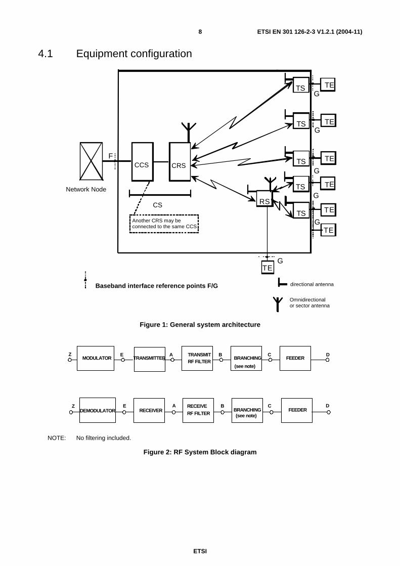
4.1 Equipment configuration
CS
CCS CRS
R S
Another CRS may be connected to the same CCS
F
G T S T E
T S T E
T S T E
T E
G
G
G
T E
T S T E
G
T S T E
G
Baseband interface reference points F/G directional antenna
Omnidirectional or sector antenna
Network Node
Figure 1: General system architecture
MODULATOR TRANSMITTER
Z E A TRANSMIT RF FILTER
B BRANCHING
C D FEEDER
C FEEDER BRANCHING
RF FILTER (see note)
B RECEIVE A RECEIVER
E DEMODULATOR
Z
(see note)
D
NOTE: No filtering included.
Figure 2: RF System Block diagram
ETSI
ETSI EN 301 126-2-3 V1.2.1 (2004-11) 9
4.1.1 System configuration
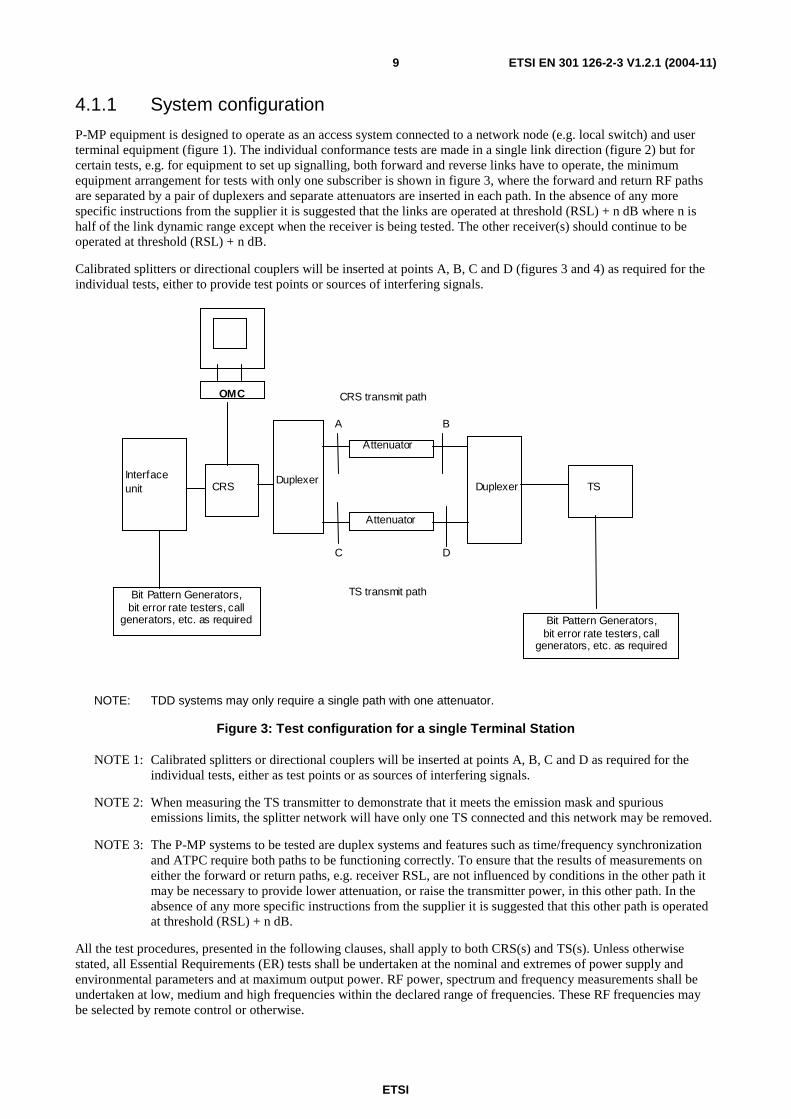
P-MP equipment is designed to operate as an access system connected to a network node (e.g. local switch) and user terminal equipment (figure 1). The individual conformance tests are made in a single link direction (figure 2) but for certain tests, e.g. for equipment to set up signalling, both forward and reverse links have to operate, the minimum equipment arrangement for tests with only one subscriber is shown in figure 3, where the forward and return RF paths are separated by a pair of duplexers and separate attenuators are inserted in each path. In the absence of any more specific instructions from the supplier it is suggested that the links are operated at threshold (RSL) + n dB where n is half of the link dynamic range except when the receiver is being tested. The other receiver(s) should continue to be operated at threshold (RSL) + n dB.
Calibrated splitters or directional couplers will be inserted at points A, B, C and D (figures 3 and 4) as required for the individual tests, either to provide test points or sources of interfering signals.
Attenuator
Attenuator
Duplexer Duplexer TS CRS
TS transmit path
CRS transmit path
Interface unit
C D
B A
Bit Pattern Generators, bit error rate testers, call
generators, etc. as required Bit Pattern Generators, bit error rate testers, call
generators, etc. as required
OMC
NOTE: TDD systems may only require a single path with one attenuator.
Figure 3: Test configuration for a single Terminal Station
NOTE 1: Calibrated splitters or directional couplers will be inserted at points A, B, C and D as required for the individual tests, either as test points or as sources of interfering signals.
NOTE 2: When measuring the TS transmitter to demonstrate that it meets the emission mask and spurious emissions limits, the splitter network will have only one TS connected and this network may be removed.
NOTE 3: The P-MP systems to be tested are duplex systems and features such as time/frequency synchronization and ATPC require both paths to be functioning correctly. To ensure that the results of measurements on either the forward or return paths, e.g. receiver RSL, are not influenced by conditions in the other path it may be necessary to provide lower attenuation, or raise the transmitter power, in this other path. In the absence of any more specific instructions from the supplier it is suggested that this other path is operated at threshold (RSL) + n dB.
All the test procedures, presented in the following clauses, shall apply to both CRS(s) and TS(s). Unless otherwise stated, all Essential Requirements (ER) tests shall be undertaken at the nominal and extremes of power supply and environmental parameters and at maximum output power. RF power, spectrum and frequency measurements shall be undertaken at low, medium and high frequencies within the declared range of frequencies. These RF frequencies may be selected by remote control or otherwise.

ETSI
ETSI EN 301 126-2-3 V1.2.1 (2004-11) 10
Central or remote stations incorporating integral antennas shall be provided with an appropriate coaxial or waveguide transition by the supplier in order to facilitate the measurements described.
For tests where the simultaneous use of several TSs is necessary, then an arrangement similar to that shown in figure 4 is required. To enable communication, the traffic load may be simulated and facilities such as remote loop back may be used to route traffic through the system.
This arrangement ensures that the system operates in a normal manner similar to its configuration for measurements such as transmitter mask and RSL.
Attenuator
Attenuator
Dup
lexe
r
Dup
lexe
r
TS
TS
Enable communications
TS
TS
CRS
TS transmit path (see note)
CRS transmit path (see note)
Interface unit
C D
B A
Bit Pattern Generators, bit error rate testers, call generators etc. as
required
Bit Pattern Generators, bit error rate testers,
call generators etc. as required
N w
ay s
plit
ter
netw
ork
incl
udin
g at
tenu
ator
et
c. i
f req
uire
d fo
r is
ola
tion
betw
een
TSs
NOTE: TDD systems may only require a single path with one attenuator.
Figure 4: Test Configuration for multiple Terminal Stations
4.2 Transmitter characteristics
4.2.1 Maximum RF output power
Objective:
Verify that the highest average RF output power measured during a transmission burst at reference point B'or C' (figure 5) is within the supplier's declared value, plus/minus the EN/ETS tolerance, and does not exceed the EN/ETS maximum value. For the CRS this may be done using a power meter with all time slots transmitting at maximum power. For the TS this may be done by synchronizing the power measurement with the active burst(s) or correcting the power with a correction due to the on/off duty cycle.
Test instruments:
Average Power Meter with a time gating function or an appropriate alternate.
ETSI
ETSI EN 301 126-2-3 V1.2.1 (2004-11) 11
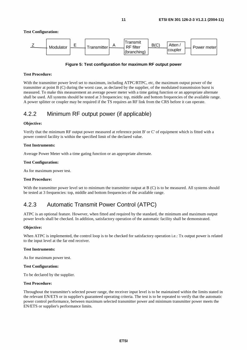
Test Configuration:
Z E A B(C)
Modulator
Transmitter
Transmit RF filter (branching)
Atten / coupler
Power meter
Figure 5: Test configuration for maximum RF output power
Test Procedure:
With the transmitter power level set to maximum, including ATPC/RTPC, etc, the maximum output power of the transmitter at point B (C) during the worst case, as declared by the supplier, of the modulated transmission burst is measured. To make this measurement an average power meter with a time gating function or an appropriate alternate shall be used. All systems should be tested at 3 frequencies: top, middle and bottom frequencies of the available range. A power splitter or coupler may be required if the TS requires an RF link from the CRS before it can operate.
4.2.2 Minimum RF output power (if applicable)
Objective:
Verify that the minimum RF output power measured at reference point B' or C' of equipment which is fitted with a power control facility is within the specified limit of the declared value.
Test Instruments:
Average Power Meter with a time gating function or an appropriate alternate.
Test Configuration:
As for maximum power test.
Test Procedure:
With the transmitter power level set to minimum the transmitter output at B (C) is to be measured. All systems should be tested at 3 frequencies: top, middle and bottom frequencies of the available range.
4.2.3 Automatic Transmit Power Control (ATPC)
ATPC is an optional feature. However, when fitted and required by the standard, the minimum and maximum output power levels shall be checked. In addition, satisfactory operation of the automatic facility shall be demonstrated.
Objective:
When ATPC is implemented, the control loop is to be checked for satisfactory operation i.e.: Tx output power is related to the input level at the far end receiver.
Test Instruments:
As for maximum power test.
Test Configuration:
To be declared by the supplier.
Test Procedure:
Throughout the transmitter's selected power range, the receiver input level is to be maintained within the limits stated in the relevant EN/ETS or in supplier's guaranteed operating criteria. The test is to be repeated to verify that the automatic power control performance, between maximum selected transmitter power and minimum transmitter power meets the EN/ETS or supplier's performance limits.
ETSI
ETSI EN 301 126-2-3 V1.2.1 (2004-11) 12
4.2.4 Remote Transmit Power Control (RTPC)
Where remote transmit power control option is fitted, it may be checked and recorded during the transmitter output power test. The maximum power shall not exceed that applied in clause 4.2.1 as an essential requirement.
4.2.5 Frequency accuracy
Objective:
To verify that the Tx output frequency is within the limits specified in the relevant EN/ETS.
NOTE 1: For systems that do not shut down on loss of synchronization, frequency accuracy should also be measured in the non-synchronized condition.
Test Instruments:
either:
1) Frequency Counter capable of measuring modulated signals;
2) Spectrum Analyser with an accurate frequency reference (recommended two orders of magnitude greater than the allowed limit), internal or external.
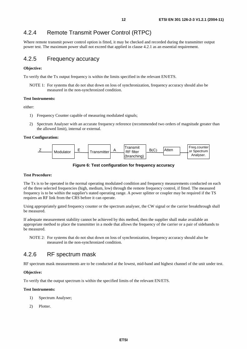
Test Configuration:
Z E A B(C)
Modulator
Transmitter
Transmit RF filter (branching)
Atten Freq.counter or Spectrum
Analyser.
Figure 6: Test configuration for frequency accuracy
Test Procedure:
The Tx is to be operated in the normal operating modulated condition and frequency measurements conducted on each of the three selected frequencies (high, medium, low) through the remote frequency control, if fitted. The measured frequency is to be within the supplier's stated operating range. A power splitter or coupler may be required if the TS requires an RF link from the CRS before it can operate.
Using appropriately gated frequency counter or the spectrum analyser, the CW signal or the carrier breakthrough shall be measured.
If adequate measurement stability cannot be achieved by this method, then the supplier shall make available an appropriate method to place the transmitter in a mode that allows the frequency of the carrier or a pair of sidebands to be measured.
NOTE 2: For systems that do not shut down on loss of synchronization, frequency accuracy should also be measured in the non-synchronized condition.
4.2.6 RF spectrum mask
RF spectrum mask measurements are to be conducted at the lowest, mid-band and highest channel of the unit under test.
Objective:
To verify that the output spectrum is within the specified limits of the relevant EN/ETS.
Test Instruments:
1) Spectrum Analyser;
2) Plotter.
ETSI
ETSI EN 301 126-2-3 V1.2.1 (2004-11) 13
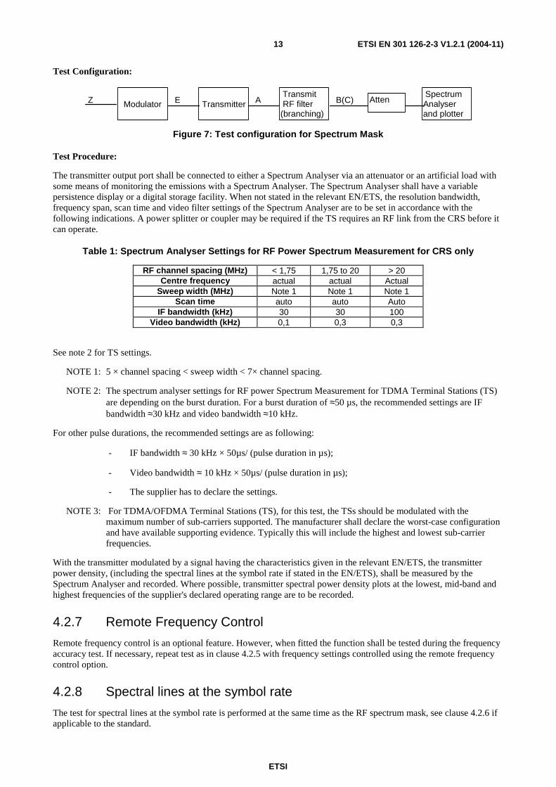
Test Configuration:
Z E A B(C)
Modulator
Transmitter
Transmit RF filter (branching)
Atten Spectrum Analyser and plotter
Figure 7: Test configuration for Spectrum Mask
Test Procedure:
The transmitter output port shall be connected to either a Spectrum Analyser via an attenuator or an artificial load with some means of monitoring the emissions with a Spectrum Analyser. The Spectrum Analyser shall have a variable persistence display or a digital storage facility. When not stated in the relevant EN/ETS, the resolution bandwidth, frequency span, scan time and video filter settings of the Spectrum Analyser are to be set in accordance with the following indications. A power splitter or coupler may be required if the TS requires an RF link from the CRS before it can operate.
Table 1: Spectrum Analyser Settings for RF Power Spectrum Measurement for CRS only
RF channel spacing (MHz) < 1,75 1,75 to 20 > 20 Centre frequency actual actual Actual
Sweep width (MHz) Note 1 Note 1 Note 1 Scan time auto auto Auto
IF bandwidth (kHz) 30 30 100 Video bandwidth (kHz) 0,1 0,3 0,3
See note 2 for TS settings.
NOTE 1: 5 × channel spacing < sweep width < 7× channel spacing.
NOTE 2: The spectrum analyser settings for RF power Spectrum Measurement for TDMA Terminal Stations (TS) are depending on the burst duration. For a burst duration of ≈50 µs, the recommended settings are IF bandwidth ≈30 kHz and video bandwidth ≈10 kHz.
For other pulse durations, the recommended settings are as following:
- IF bandwidth ≈ 30 kHz × 50µs/ (pulse duration in µs);
- Video bandwidth ≈ 10 kHz × 50µs/ (pulse duration in µs);
- The supplier has to declare the settings.
NOTE 3: For TDMA/OFDMA Terminal Stations (TS), for this test, the TSs should be modulated with the maximum number of sub-carriers supported. The manufacturer shall declare the worst-case configuration and have available supporting evidence. Typically this will include the highest and lowest sub-carrier frequencies.
With the transmitter modulated by a signal having the characteristics given in the relevant EN/ETS, the transmitter power density, (including the spectral lines at the symbol rate if stated in the EN/ETS), shall be measured by the Spectrum Analyser and recorded. Where possible, transmitter spectral power density plots at the lowest, mid-band and highest frequencies of the supplier's declared operating range are to be recorded.
4.2.7 Remote Frequency Control
Remote frequency control is an optional feature. However, when fitted the function shall be tested during the frequency accuracy test. If necessary, repeat test as in clause 4.2.5 with frequency settings controlled using the remote frequency control option.
4.2.8 Spectral lines at the symbol rate
The test for spectral lines at the symbol rate is performed at the same time as the RF spectrum mask, see clause 4.2.6 if applicable to the standard.
ETSI
ETSI EN 301 126-2-3 V1.2.1 (2004-11) 14
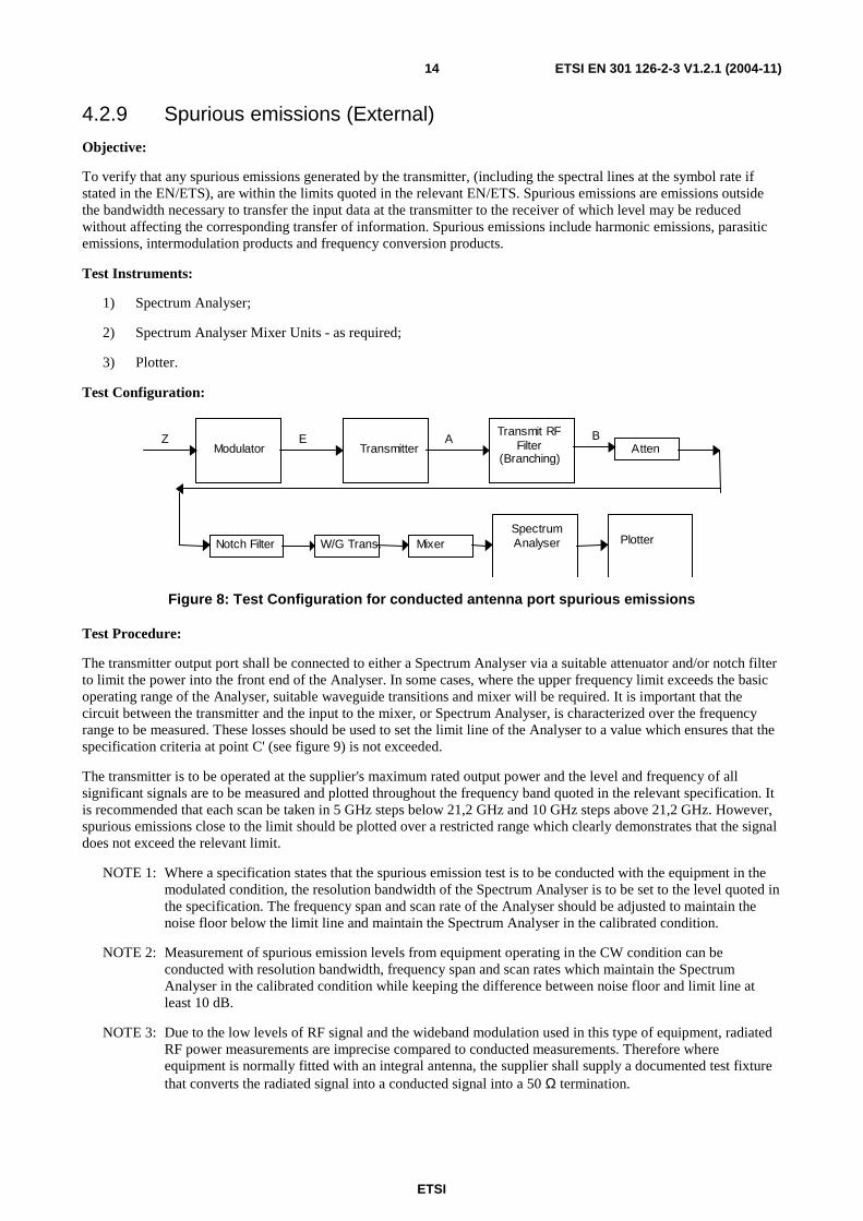
4.2.9 Spurious emissions (External)
Objective:
To verify that any spurious emissions generated by the transmitter, (including the spectral lines at the symbol rate if stated in the EN/ETS), are within the limits quoted in the relevant EN/ETS. Spurious emissions are emissions outside the bandwidth necessary to transfer the input data at the transmitter to the receiver of which level may be reduced without affecting the corresponding transfer of information. Spurious emissions include harmonic emissions, parasitic emissions, intermodulation products and frequency conversion products.
Test Instruments:
1) Spectrum Analyser;
2) Spectrum Analyser Mixer Units - as required;
3) Plotter.
Test Configuration:
Z E A B Modulator Transmitter
Transmit RF Filter
(Branching) Atten
Spectrum Analyser Plotter Notch Filter W/G Trans. Mixer
Figure 8: Test Configuration for conducted antenna port spurious emissions
Test Procedure:
The transmitter output port shall be connected to either a Spectrum Analyser via a suitable attenuator and/or notch filter to limit the power into the front end of the Analyser. In some cases, where the upper frequency limit exceeds the basic operating range of the Analyser, suitable waveguide transitions and mixer will be required. It is important that the circuit between the transmitter and the input to the mixer, or Spectrum Analyser, is characterized over the frequency range to be measured. These losses should be used to set the limit line of the Analyser to a value which ensures that the specification criteria at point C' (see figure 9) is not exceeded.
The transmitter is to be operated at the supplier's maximum rated output power and the level and frequency of all significant signals are to be measured and plotted throughout the frequency band quoted in the relevant specification. It is recommended that each scan be taken in 5 GHz steps below 21,2 GHz and 10 GHz steps above 21,2 GHz. However, spurious emissions close to the limit should be plotted over a restricted range which clearly demonstrates that the signal does not exceed the relevant limit.
NOTE 1: Where a specification states that the spurious emission test is to be conducted with the equipment in the modulated condition, the resolution bandwidth of the Spectrum Analyser is to be set to the level quoted in the specification. The frequency span and scan rate of the Analyser should be adjusted to maintain the noise floor below the limit line and maintain the Spectrum Analyser in the calibrated condition.
NOTE 2: Measurement of spurious emission levels from equipment operating in the CW condition can be conducted with resolution bandwidth, frequency span and scan rates which maintain the Spectrum Analyser in the calibrated condition while keeping the difference between noise floor and limit line at least 10 dB.
NOTE 3: Due to the low levels of RF signal and the wideband modulation used in this type of equipment, radiated RF power measurements are imprecise compared to conducted measurements. Therefore where equipment is normally fitted with an integral antenna, the supplier shall supply a documented test fixture that converts the radiated signal into a conducted signal into a 50 Ω termination.

ETSI
ETSI EN 301 126-2-3 V1.2.1 (2004-11) 15
NOTE 4: The RF conducted signal shall be measured into a 50 Ω coaxial line to the spectrum analyser for all frequencies below the operating frequency if below 26,5 GHz. This is to prevent any external waveguide acting as a high pass filter.
NOTE 5: For TDMA/OFDMA Terminal Stations (TS), the manufacturer shall declare, and have available supporting evidence, which sub-carriers combination supported by the TS creates the worst spurious response, and the test shall be conducted at this setting.
Where the equipment standard refers to CEPT/ERC/REC 74-01 [4], then the measurements are taken for the mean power of the spurious emissions during the transmission burst. For spurious emission measurements on the TS it may not be possible to complete a Spectrum Analyser frequency scan during a synchronized pulse. (i.e. the sweep time of the spectrum analyser is much greater than the pulse time of the TS). In this case it shall be deemed that if the peak power over a statistically sufficient number of spectrum analyser sweeps is below the mean power limit, that the mean power limit is met. If this cannot be shown, then alternatives may be used as long as they detail the rational behind the measurements in the report.
Measurements shall be made in accordance to the Published standard. Any variations shall be detailed and agreed with each Nation Regulator.
4.3 Receiver characteristics
4.3.1 Input level range (if applicable)
Objective:
To verify that the receiver meets the BER criteria, given in the relevant specification, over a defined range of receiver input levels.
Test Instruments:
See test procedure for BER versus Receiver input level (clause 4.3.3.2).
Test Configuration:
Var. Att.
Power Sensor
Power Meter
Modulator Transmitter B(C)
Pattern Generator
Z
Demodulator E B (C)
Receiver under
test
E
Z
Error Dectector
Figure 9: Test Configuration for input level range
Test Procedure:
Connect the pattern generator output to the BB transmitter input Z' and the error detector to the BB Rx output Z. Switch the transmitter to standby and adjust the variable attenuator to provide maximum attenuation. Disconnect the receiver under test. Connect the power meter, through a suitable power sensor, to point B(C) (figure 9). Switch on the transmitter and adjust the attenuator to set the power to the upper limit for the input level range test. Switch the transmitter to standby and reconnect the receiver under test.
The input level to the Rx shall be set to the upper and lower levels specified in the relevant ETS/EN or declared by the manufacturer, which ever is the greater and the BER at those RSLs recorded. If required increase the level of attenuation until the signal input level at the receiver causes BER equal to the limit quoted in the relevant specification and calculate the signal level i.e. upper receiver input level minus increase in attenuation. The receiver input level range is the signal range between the upper and lower receiver input levels.
ETSI
ETSI EN 301 126-2-3 V1.2.1 (2004-11) 16
NOTE 1: When the base band interface precludes the use of a Bit Error Ratio detector, e.g. in a packet data system, another measure of error performance may be specified by the supplier provided that its numerical equivalence to the BER test can be shown. This proof of equivalence should be recorded in the report.
NOTE 2: For TDMA/OFDMA Terminal Stations (TS), for this test, the TSs should be modulated with the maximum number of sub-carriers supported. The RSL should be scaled according to actual occupied portion of the channel bandwidth and a sample calculation recorded in the report.
4.3.2 Spurious emissions
The same test method as described in clause 4.2.9 is applicable. Spurious emission levels from a transmitter and receiver of duplex equipment using a common port are measured simultaneously and the test only needs to be conducted once.
Objective:
To verify that spurious emissions from the receiver are within the limits.
4.4 System Characteristics
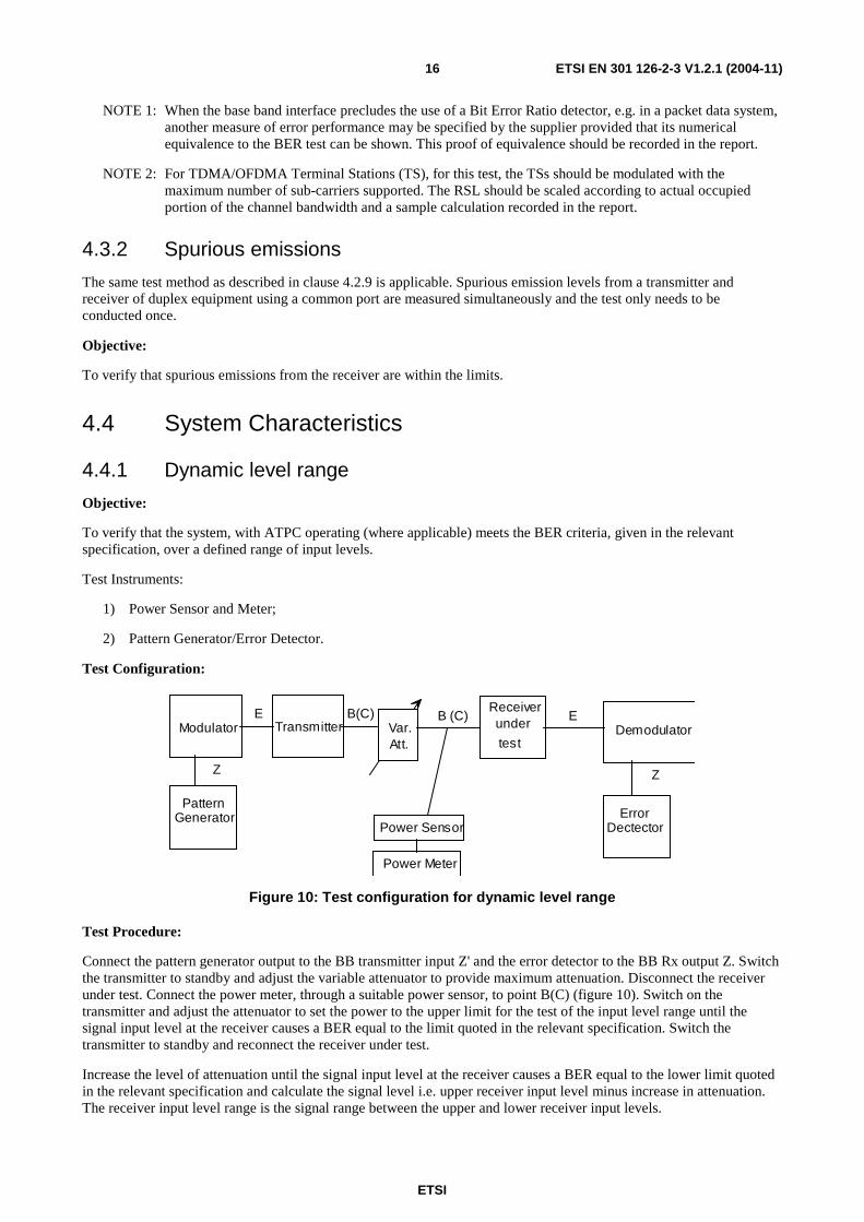
4.4.1 Dynamic level range
Objective:
To verify that the system, with ATPC operating (where applicable) meets the BER criteria, given in the relevant specification, over a defined range of input levels.
Test Instruments:
1) Power Sensor and Meter;
2) Pattern Generator/Error Detector.
Test Configuration:
Var. Att.
Power Sensor
Power Meter
Modulator Transmitter B(C)
Pattern Generator
Z
Demodulator E B (C)
Receiver under
test
E
Z
Error Dectector
Figure 10: Test configuration for dynamic level range
Test Procedure:
Connect the pattern generator output to the BB transmitter input Z' and the error detector to the BB Rx output Z. Switch the transmitter to standby and adjust the variable attenuator to provide maximum attenuation. Disconnect the receiver under test. Connect the power meter, through a suitable power sensor, to point B(C) (figure 10). Switch on the transmitter and adjust the attenuator to set the power to the upper limit for the test of the input level range until the signal input level at the receiver causes a BER equal to the limit quoted in the relevant specification. Switch the transmitter to standby and reconnect the receiver under test.
Increase the level of attenuation until the signal input level at the receiver causes a BER equal to the lower limit quoted in the relevant specification and calculate the signal level i.e. upper receiver input level minus increase in attenuation. The receiver input level range is the signal range between the upper and lower receiver input levels.

ETSI
ETSI EN 301 126-2-3 V1.2.1 (2004-11) 17
The dynamic input level range is calculated by the measured input level range between the upper and the lower receiver input level referred to a specified BER (any built-in attenuator in the signal path is to be taken into account) increased by the declared and measured control range of an ATPC or a RTPC (see clauses 4.2.3 and 4.2.4).
4.4.2 BER as a function of receiver input signal level RSL
Objective:
To verify that the received signal levels versus BER thresholds are within the limits specified, (at a minimum of two BER levels), in the relevant EN/ETS.
Test Instruments:
1) Pattern Generator/Error Detector;
2) Power Sensor and Meter.
Test Configuration:
Pattern
Generator Transmitter Receiver Error
Detector
Pow er Sensor
Pow er Meter
Z B(C) B(C) Z Attenuator
Figure 11: Test configuration for BER as a function of RSL
Test Procedure:
Connect the pattern generator output to the BB input of the transmitter. Send the BB output signal of the Rx to the Error Detector. Then take record of BER curve by varying the received level. Verify that the RSL, corresponding to the BER thresholds are within the specifications.
NOTE: For TDMA/OFDMA Terminal Stations (TS), the maximum number of sub-carriers supported by the TS should be modulated for this test. The RSL should be scaled according to actual occupied portion of the channel bandwidth and a sample calculation recorded in the report.
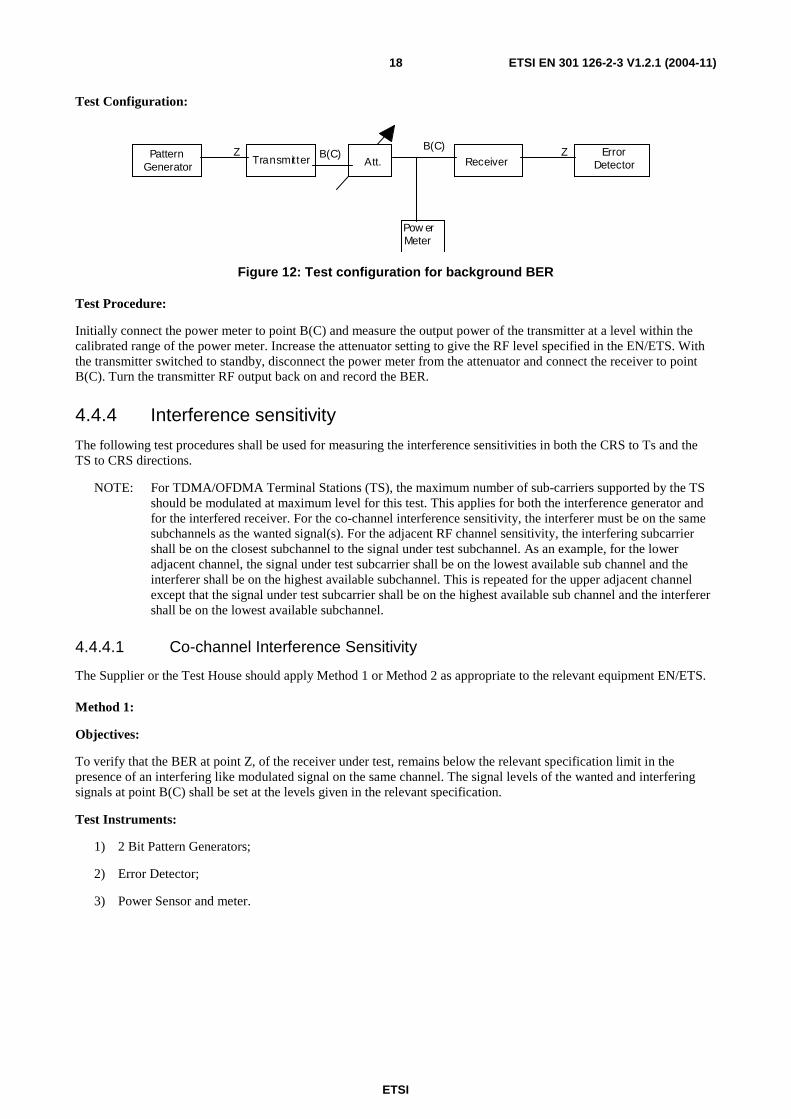
4.4.3 Equipment Background BER
Objective:
To verify that the equipment background BER is below the value specified in the relevant EN/ETS.
Test Instruments:
1) Pattern Generator/Error Detector;
2) Power Meter.
ETSI
ETSI EN 301 126-2-3 V1.2.1 (2004-11) 18
Test Configuration:
Z B(C) Z Pattern Generator T r a n s m i t t e r
Pow er Meter
Receiver Error
Detector Att. B(C)
Figure 12: Test configuration for background BER
Test Procedure:
Initially connect the power meter to point B(C) and measure the output power of the transmitter at a level within the calibrated range of the power meter. Increase the attenuator setting to give the RF level specified in the EN/ETS. With the transmitter switched to standby, disconnect the power meter from the attenuator and connect the receiver to point B(C). Turn the transmitter RF output back on and record the BER.
4.4.4 Interference sensitivity
The following test procedures shall be used for measuring the interference sensitivities in both the CRS to Ts and the TS to CRS directions.
NOTE: For TDMA/OFDMA Terminal Stations (TS), the maximum number of sub-carriers supported by the TS should be modulated at maximum level for this test. This applies for both the interference generator and for the interfered receiver. For the co-channel interference sensitivity, the interferer must be on the same subchannels as the wanted signal(s). For the adjacent RF channel sensitivity, the interfering subcarrier shall be on the closest subchannel to the signal under test subchannel. As an example, for the lower adjacent channel, the signal under test subcarrier shall be on the lowest available sub channel and the interferer shall be on the highest available subchannel. This is repeated for the upper adjacent channel except that the signal under test subcarrier shall be on the highest available sub channel and the interferer shall be on the lowest available subchannel.
4.4.4.1 Co-channel Interference Sensitivity
The Supplier or the Test House should apply Method 1 or Method 2 as appropriate to the relevant equipment EN/ETS.
Method 1:
Objectives:
To verify that the BER at point Z, of the receiver under test, remains below the relevant specification limit in the presence of an interfering like modulated signal on the same channel. The signal levels of the wanted and interfering signals at point B(C) shall be set at the levels given in the relevant specification.
Test Instruments:
1) 2 Bit Pattern Generators;
2) Error Detector;
3) Power Sensor and meter.

ETSI
ETSI EN 301 126-2-3 V1.2.1 (2004-11) 19
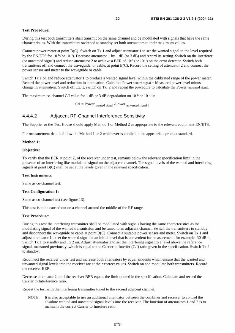
Test Configuration 1:
Modulator Tx 1
Modulator Tx 2
Bit Pattern Generator
Bit Pattern Generator
Attenuator 1
Attenuator 2
Coupler Attenuator 3 Receiver
BER Tester Power
Meter
B(C)
B(C)
Demod
E
E
E
Figure 13: Test configuration for Co-channel Interference Sensitivity - external
This test is to be carried out on a channel around the middle of the RF range.
Test Procedure:
During this test both transmitters shall transmit on the same frequency and be modulated with different signals having the same characteristics. Switch the transmitters to standby and disconnect the waveguide or cable at point B(C) (see figure 13). Connect a suitable power sensor and meter. Switch on Tx 1 and adjust attenuator 1 to set the signal to a convenient level within the receiver input level range which will be the reference level. Switch Tx 1 to standby and Tx 2 on. Adjust attenuator 2 to set the interfering signal to a level below the reference level, measured previously, which is defined by the Carrier to Interfer (C/I) ratio given in the specification. Switch Tx 2 to standby.
Reconnect the receiver under test, switch on Tx 1 and increase attenuator 1 until the BER required by the EN/ETS is achieved. Increase attenuator 2 by the same amount attenuator 1 was increased, switch on Tx 2 and record the BER.
NOTE: It is also acceptable to use an additional attenuator between the coupler and receiver (point B(C)) to control the absolute wanted and unwanted signal levels into the receiver. The function of attenuators 1 and 2 is to maintain the correct Carrier to Interference ratio.
Method 2:
Objective:
To verify that the maximum C/I value for 1 dB and 3 dB degradation on 10-6 and 10-3 BER remains below the relevant specification limit in presence of an interfering like modulated signal on the same channel.
Test Instruments:
1) 2 Pattern Generator;
2) Error Detector;
3) Power Sensor and Meter.
Test Configuration 2:
See figure 13.
This test is to be carried out on a channel around the middle of the RF range.
ETSI
ETSI EN 301 126-2-3 V1.2.1 (2004-11) 20
Test Procedure:
During this test both transmitters shall transmit on the same channel and be modulated with signals that have the same characteristics. With the transmitters switched to standby set both attenuators to their maximum values.
Connect power meter at point B(C). Switch on Tx 1 and adjust attenuator 1 to set the wanted signal to the level required by the EN/ETS for 10-6 (or 10-3). Decrease attenuator 1 by 1 dB (or 3 dB) and record its setting. Switch on the interferer (or unwanted signal) and reduce attenuator 2 to achieve a BER of 10-6 (or 10-3) on the error detector. Switch both transmitters off and connect the waveguide, or cable, at point B(C). Record the setting of attenuator 2 and connect the power sensor and meter to the waveguide or cable.
Switch Tx 1 on and reduce attenuator 1 to produce a wanted signal level within the calibrated range of the power meter. Record the power level and reduction in attenuation. Calculate Power wanted signal = Measured power level minus change in attenuation. Switch off Tx. 1, switch on Tx. 2 and repeat the procedure to calculate the Power unwanted signal.
The maximum co-channel C/I value for 1 dB or 3 dB degradation on 10-6 or 10-3 is:
C/I = Power wanted signal /Power unwanted signal l
4.4.4.2 Adjacent RF-Channel Interference Sensitivity
The Supplier or the Test House should apply Method 1 or Method 2 as appropriate to the relevant equipment EN/ETS.
For measurement details follow the Method 1 or 2 whichever is applied to the appropriate product standard.
Method 1:
Objective:
To verify that the BER at point Z, of the receiver under test, remains below the relevant specification limit in the presence of an interfering like modulated signal on the adjacent channel. The signal levels of the wanted and interfering signals at point B(C) shall be set at the levels given in the relevant specification.
Test Instruments:
Same as co-channel test.
Test Configuration 1:
Same as co-channel test (see figure 13).
This test is to be carried out on a channel around the middle of the RF range.
Test Procedure:
During this test the interfering transmitter shall be modulated with signals having the same characteristics as the modulating signal of the wanted transmission and be tuned to an adjacent channel. Switch the transmitters to standby and disconnect the waveguide or cable at point B(C). Connect a suitable power sensor and meter. Switch on Tx 1 and adjust attenuator 1 to set the wanted signal at an initial level that is convenient for measurement, for example -30 dBm. Switch Tx 1 to standby and Tx 2 on. Adjust attenuator 2 to set the interfering signal to a level above the reference signal, measured previously, which is equal to the Carrier to Interfer (C/I) ratio given in the specification. Switch Tx 2 to standby.
Reconnect the receiver under test and increase both attenuators by equal amounts which ensure that the wanted and unwanted signal levels into the receiver are at their correct values. Switch on and modulate both transmitters. Record the receiver BER.
Decrease attenuator 2 until the receiver BER equals the limit quoted in the specification. Calculate and record the Carrier to Interference ratio.
Repeat the test with the interfering transmitter tuned to the second adjacent channel.
NOTE: It is also acceptable to use an additional attenuator between the combiner and receiver to control the absolute wanted and unwanted signal levels into the receiver. The function of attenuators 1 and 2 is to maintain the correct Carrier to Interfere ratio.

ETSI
ETSI EN 301 126-2-3 V1.2.1 (2004-11) 21
Method 2:
Objective:
To verify that the maximum C/I value [for 1 dB and 3 dB degradation on 10-6 and 10-3 BER] remains below the relevant specification limit in the presence of an interfering like modulated signal on the adjacent channel.
Test Instruments:
1) 2 Pattern Generator;
2) Error Detector;
3) Power Sensor and Meter.
Test Configuration:
Same as co-channel test. (see figure 13).
This test is to be carried out on a channel around the middle of the RF range.
Test Procedure:
During this test the interferer (or unwanted signal, Tx. 2) shall transmit on one of the adjacent channels and be modulated with a signal having the same characteristics as the signal modulating the wanted transmitter. With both transmitters on standby set the attenuators to their maximum values.
Connect power meter at point B(C). Switch on Tx 1 and adjust attenuator 1 to set the wanted signal to the level required by the ETS for 10-6
(or 10-3). Decrease attenuator 1 by 1 dB (or 3 dB) and record its setting. Switch on the interferer or
unwanted signal and reduce attenuator 2 to achieve a BER of 10-6 (or 10-3) on the error detector. Switch both transmitters off and disconnect the waveguide, or cable, at point B(C). Record the setting of attenuator 2 and connect the power sensor and meter to the waveguide or cable.
Switch Tx. 1 on and reduce attenuator 1 to produce a wanted signal level within the calibrated range of the power meter. Record the power level and reduction in attenuation. Calculate Power wanted signal = Measured power level minus
change in attenuation. Switch off Tx. 1, switch on Tx. 2 and repeat the procedure to calculate the Power unwanted signal.
The maximum co-channel C/I value for 1 dB or 3 dB degradation on 10-6 or 10-3 is:
C/I = Power wanted signal/Power unwanted signal.
Repeat the test with the interferer on the second adjacent channel.
4.4.4.3 CW Spurious Interference
Objective:
This test is designed to identify specific frequencies at which the receiver may have a spurious response e.g. image frequency, harmonic response of the receive filter etc. The frequency range of the test should be in accordance with the relevant specification.
Test Instruments:
1) Pattern Generator;
2) Error Detector;
3) Signal Generator;
4) Power Sensor and Meter.
ETSI
ETSI EN 301 126-2-3 V1.2.1 (2004-11) 22
Test Configuration:
Error Detector
Combiner
Pattern Generator
Transmitter + Receiver
Signal Generator
Z B(C)
B(C) Z
Attn.
Pow er Sensor Pow er Sensor
Pow er Meter Pow er Meter
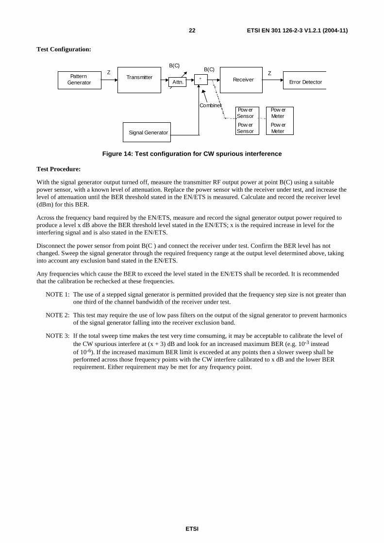
Figure 14: Test configuration for CW spurious interference
Test Procedure:
With the signal generator output turned off, measure the transmitter RF output power at point B(C) using a suitable power sensor, with a known level of attenuation. Replace the power sensor with the receiver under test, and increase the level of attenuation until the BER threshold stated in the EN/ETS is measured. Calculate and record the receiver level (dBm) for this BER.
Across the frequency band required by the EN/ETS, measure and record the signal generator output power required to produce a level x dB above the BER threshold level stated in the EN/ETS; x is the required increase in level for the interfering signal and is also stated in the EN/ETS.
Disconnect the power sensor from point B(C ) and connect the receiver under test. Confirm the BER level has not changed. Sweep the signal generator through the required frequency range at the output level determined above, taking into account any exclusion band stated in the EN/ETS.
Any frequencies which cause the BER to exceed the level stated in the EN/ETS shall be recorded. It is recommended that the calibration be rechecked at these frequencies.
NOTE 1: The use of a stepped signal generator is permitted provided that the frequency step size is not greater than one third of the channel bandwidth of the receiver under test.
NOTE 2: This test may require the use of low pass filters on the output of the signal generator to prevent harmonics of the signal generator falling into the receiver exclusion band.
NOTE 3: If the total sweep time makes the test very time consuming, it may be acceptable to calibrate the level of the CW spurious interfere at (x + 3) dB and look for an increased maximum BER (e.g. 10-3 instead of 10-6). If the increased maximum BER limit is exceeded at any points then a slower sweep shall be performed across those frequency points with the CW interfere calibrated to x dB and the lower BER requirement. Either requirement may be met for any frequency point.

ETSI
ETSI EN 301 126-2-3 V1.2.1 (2004-11) 23
History
Document history
V1.1.1 November 2000 Publication
V1.2.1 July 2004 One-step Approval Procedure OAP 20041112: 2004-07-14 to 2004-11-12
V1.2.1 November 2004 Publication