en 301 649 - v2.3.1 - digital enhanced cordless … · 2015-03-27 · sous-préfecture de grasse...
TRANSCRIPT

ETSI EN 301 649 V2.3.1 (2015-03)
Digital Enhanced Cordless Telecommunications (DECT); DECT Packet Radio Service (DPRS)
EUROPEAN STANDARD

ETSI
ETSI EN 301 649 V2.3.1 (2015-03)2
Reference REN/DECT-00305
Keywords access, data, DECT, DPRS, frame relay,
IMT-2000, internet, interoperability, interworking, IP, IPv6, LAN, mobility, multimedia, packet mode,
profile, radio, synchronization, TDD, TDMA
ETSI
650 Route des Lucioles F-06921 Sophia Antipolis Cedex - FRANCE
Tel.: +33 4 92 94 42 00 Fax: +33 4 93 65 47 16
Siret N° 348 623 562 00017 - NAF 742 C
Association à but non lucratif enregistrée à la Sous-Préfecture de Grasse (06) N° 7803/88
Important notice
The present document can be downloaded from: http://www.etsi.org/standards-search
The present document may be made available in electronic versions and/or in print. The content of any electronic and/or print versions of the present document shall not be modified without the prior written authorization of ETSI. In case of any
existing or perceived difference in contents between such versions and/or in print, the only prevailing document is the print of the Portable Document Format (PDF) version kept on a specific network drive within ETSI Secretariat.
Users of the present document should be aware that the document may be subject to revision or change of status. Information on the current status of this and other ETSI documents is available at
http://portal.etsi.org/tb/status/status.asp
If you find errors in the present document, please send your comment to one of the following services: https://portal.etsi.org/People/CommiteeSupportStaff.aspx
Copyright Notification
No part may be reproduced or utilized in any form or by any means, electronic or mechanical, including photocopying and microfilm except as authorized by written permission of ETSI.
The content of the PDF version shall not be modified without the written authorization of ETSI. The copyright and the foregoing restriction extend to reproduction in all media.
© European Telecommunications Standards Institute 2015.
All rights reserved.
DECTTM, PLUGTESTSTM, UMTSTM and the ETSI logo are Trade Marks of ETSI registered for the benefit of its Members. 3GPPTM and LTE™ are Trade Marks of ETSI registered for the benefit of its Members and
of the 3GPP Organizational Partners. GSM® and the GSM logo are Trade Marks registered and owned by the GSM Association.

ETSI
ETSI EN 301 649 V2.3.1 (2015-03)3
Contents Intellectual Property Rights ...................................................................................................................... 15
Foreword ................................................................................................................................................... 15
Modal verbs terminology .......................................................................................................................... 15
1 Scope .............................................................................................................................................. 16
2 References ...................................................................................................................................... 16
2.1 Normative references .............................................................................................................................. 16
2.2 Informative references ............................................................................................................................. 18
3 Definitions, symbols and abbreviations ......................................................................................... 19
3.1 Definitions ............................................................................................................................................... 19
3.2 Symbols ................................................................................................................................................... 20
3.3 Abbreviations .......................................................................................................................................... 21
4 Description of services ................................................................................................................... 24
4.1 The DECT Packet Radio Service (DPRS) ............................................................................................... 24
4.1.1 Service objectives .............................................................................................................................. 24
4.1.2 Characteristics of the DECT packet data service ............................................................................... 25
4.1.3 Performance Objectives ..................................................................................................................... 25
4.1.4 DPRS U-plane Services ..................................................................................................................... 26
4.1.5 DPRS operation modes (Classes) ...................................................................................................... 27
4.1.6 DPRS System Categories ................................................................................................................... 27
4.2 Protocol architecture................................................................................................................................ 28
4.2.1 Reference configuration for Internet Protocol and LANs .................................................................. 29
4.2.1.1 Reference configuration for Internet Protocol .............................................................................. 29
4.2.1.2 Reference configuration for IEEE 802.3 [13] .............................................................................. 30
4.3 Service and feature definitions ................................................................................................................ 30
4.3.1 PHL service definitions ..................................................................................................................... 30
4.3.2 MAC service definitions .................................................................................................................... 31
4.3.3 DLC service definitions ..................................................................................................................... 33
4.3.4 NWK feature definitions .................................................................................................................... 34
4.3.5 Application service definitions .......................................................................................................... 36
4.3.6 Distributed Communication ............................................................................................................... 36
4.3.7 Management Entity ............................................................................................................................ 36
4.3.8 Call Control (CC) and Mobility Management (MM) Service Class .................................................. 37
4.3.9 U-plane Service and Interworking type ............................................................................................. 37
4.3.10 DPRS System Categories ................................................................................................................... 37
4.4 General Class/Service/Interworking support ........................................................................................... 38
4.5 System categories .................................................................................................................................... 38
4.5.1 Mapping between DPRS categories and features/services ................................................................ 38
4.5.2 Supported data rates for equipment declaring compliance to a data category ................................... 40
4.5.3 Indication of compliance with a data category .................................................................................. 42
5 PHL requirements .......................................................................................................................... 43
5.1 Physical Layer services ........................................................................................................................... 43
5.2 Modulation schemes ................................................................................................................................ 43
5.3 PHL service to procedure mapping ......................................................................................................... 44
5.4 PHL layer procedures .............................................................................................................................. 44
5.4.1 General radio requirements ................................................................................................................ 44
5.4.2 Minimum Normal Transmit Power (NTP) ......................................................................................... 44
5.4.3 Radio receiver sensitivity ................................................................................................................... 45
5.4.4 Z-field ................................................................................................................................................ 45
5.4.5 Sliding collision detection ................................................................................................................. 45
5.4.6 Physical channel availability.............................................................................................................. 45
5.4.7 Synchronization window ................................................................................................................... 45
5.4.8 Power management ............................................................................................................................ 45
5.4.9 Fast hopping radio ............................................................................................................................. 45
6 MAC layer requirements ................................................................................................................ 45

ETSI
ETSI EN 301 649 V2.3.1 (2015-03)4
6.1 MAC services .......................................................................................................................................... 45
6.2 MAC service to procedure mapping ........................................................................................................ 47
7 DLC-layer requirements ................................................................................................................. 52
7.1 DLC services ........................................................................................................................................... 52
7.2 DLC feature to procedure mapping ......................................................................................................... 52
8 NWK layer requirements................................................................................................................ 53
8.1 NWK features .......................................................................................................................................... 54
8.2 NWK feature to procedure mapping ....................................................................................................... 55
8.3 Application features ................................................................................................................................ 59
8.4 Application feature to procedure mapping .............................................................................................. 59
8.5 Distributed Communications ................................................................................................................... 60
8.5.1 Distributed Communications features ................................................................................................ 60
8.6 Distributed Communications feature to procedure mapping ................................................................... 60
9 Management Entity Requirements ................................................................................................. 60
9.1 Introduction ............................................................................................................................................. 60
9.1.1 Management Entity (ME) operation modes ....................................................................................... 60
9.1.2 Management Entity (ME) mode to procedures mapping ................................................................... 61
9.2 Description of the DPRS operation principles......................................................................................... 62
9.2.1 General ............................................................................................................................................... 62
9.2.2 Service class 1 .................................................................................................................................... 62
9.2.3 Service class 2 .................................................................................................................................... 62
9.2.4 Service class 3 .................................................................................................................................... 62
9.2.5 Service class 4 .................................................................................................................................... 63
9.3 Resource and physical connection management for Class 1 and Class 2 systems .................................. 63
9.3.1 Requirements applicable to the Fixed Part (FP) ................................................................................ 63
9.3.1.1 Conditions for resumption and management procedures ............................................................. 63
9.3.1.1.1 General ................................................................................................................................... 63
9.3.1.1.2 ME procedures for FT initiated connection resumption ......................................................... 63
9.3.1.2 Connection Suspension conditions ............................................................................................... 65
9.3.1.2.1 General ................................................................................................................................... 65
9.3.1.2.2 Connection suspension due to no data activity ....................................................................... 65
9.3.1.2.3 Connection suspension due to violation of the minimum number of bearers (MAC Bandwidth command) ............................................................................................................................... 65
9.3.1.2.4 Connection suspension by loss of all received bearers ........................................................... 65
9.3.1.2.5 Activation of Fast Scan mode and/or high duty cycle paging detection after Connection suspension .............................................................................................................................. 66
9.3.1.3 Conditions for Bandwidth modification ....................................................................................... 66
9.3.1.3.1 General ................................................................................................................................... 66
9.3.2 Requirements applicable to the Portable Part (PP) ............................................................................ 66
9.3.2.1 Conditions for connection resumption ......................................................................................... 66
9.3.2.1.1 Procedure for PT initiated Connection resumption ................................................................ 66
9.3.2.1.2 "RFP-busy-for-data" flag ........................................................................................................ 67
9.3.2.1.3 Waiting time for collision avoidance after deactivation of "RFP-busy-for-data" flag ............ 67
9.3.2.1.4 Bandwidth after resumption ................................................................................................... 67
9.3.2.1.5 Resumption rejection by the FT ............................................................................................. 67
9.3.2.2 Conditions for Connection Suspension ........................................................................................ 67
9.3.2.2.1 General ................................................................................................................................... 67
9.3.2.2.2 Connection suspension due to no data activity ....................................................................... 67
9.3.2.2.3 Connection suspension due to violation of the minimum number of bearers (MAC Bandwidth command) ............................................................................................................................... 68
9.3.2.2.4 Connection suspension by loss of all received bearers ........................................................... 68
9.3.2.2.5 Activation of fast scan mode after Connection suspension .................................................... 68
9.3.2.3 Conditions for Bandwidth modification ....................................................................................... 68
9.3.2.3.1 General ................................................................................................................................... 68
9.3.2.3.2 Rules for the bandwidth request by the PP ............................................................................. 68
9.4 Logical Connection and virtual call management ................................................................................... 69
9.4.1 Requirements for class 1 devices ....................................................................................................... 69
9.4.2 Requirements for class 2 devices ....................................................................................................... 69
9.4.2.1 General Description ..................................................................................................................... 69
9.4.2.2 Normal procedures of virtual call setup and release..................................................................... 69

ETSI
ETSI EN 301 649 V2.3.1 (2015-03)5
9.4.2.2.1 Identification of the call as a DPRS call ................................................................................. 69
9.4.2.2.2 Bandwidth attributes of the call .............................................................................................. 69
9.4.2.2.3 Creation of DLC link and MAC logical connection. .............................................................. 70
9.4.2.2.4 Temporary states during the setup procedure ......................................................................... 70
9.4.2.3 Abnormal release of Virtual Calls ................................................................................................ 70
9.4.2.4 Release of Logical Connection .................................................................................................... 70
9.4.2.5 The handshake (stay alive) procedure .......................................................................................... 70
9.4.3 Requirements for class 3 devices ....................................................................................................... 71
9.4.3.1 General Description ..................................................................................................................... 71
9.4.3.1.1 Identification of the call as a DPRS call ................................................................................. 71
9.4.3.1.2 Connection attributes .............................................................................................................. 71
9.4.4 Requirements for class 4 devices ....................................................................................................... 71
9.4.4.1 General Description ..................................................................................................................... 71
9.4.4.1.1 Identification of the call as a DPRS call ................................................................................. 72
9.5 Resource and physical connection management for Class 3 and Class 4 devices ................................... 72
9.5.1 Simplified Class 3 connection management ...................................................................................... 72
9.5.2 Suspend management (Tx side) ......................................................................................................... 72
9.5.3 Suspend management (Rx side) ......................................................................................................... 72
9.5.4 Resume management ......................................................................................................................... 72
9.5.5 Stay alive (timer control) ................................................................................................................... 72
9.5.6 Stay alive (periodic resume) .............................................................................................................. 72
9.5.7 Simplified Class 4 connection management ...................................................................................... 73
10 MAC layer procedures ................................................................................................................... 73
10.1 General .................................................................................................................................................... 73
10.1.1 Frame and multiframe structure ......................................................................................................... 73
10.1.2 Bit mappings ...................................................................................................................................... 73
10.1.2.1 Multiple bitmappings rule ............................................................................................................ 73
10.1.3 Void ................................................................................................................................................... 73
10.1.4 Scrambling ......................................................................................................................................... 73
10.1.5 Error control....................................................................................................................................... 73
10.1.6 Void ................................................................................................................................................... 73
10.1.7 Void ................................................................................................................................................... 73
10.1.8 RFP idle receiver scan sequence ........................................................................................................ 74
10.1.9 PT receiver scan sequence ................................................................................................................. 74
10.1.10 PT states and state transitions ............................................................................................................ 74
10.1.10.1 PT states and state transitions for PTs not supporting fast setup .................................................. 74
10.1.10.2 PT states and state transitions for PTs supporting fast setup ........................................................ 74
10.1.10.2.1 Fast setup control information provided by the FT ................................................................ 75
10.1.10.2.2 PT states and state transitions when PT and FT supports complete setup detection .............. 75
10.1.10.2.3 PT states and state transitions when PT and FT supports Selective setup detection only ...... 76
10.1.10.2.4 Fast setup control information provided using MAC paging ................................................. 76
10.1.11 Identities ............................................................................................................................................ 77
10.2 Non continuous broadcast ....................................................................................................................... 77
10.2.1 Request for specific Q channel information....................................................................................... 77
10.2.2 Request for a new dummy ................................................................................................................. 77
10.3 Downlink broadcast ................................................................................................................................. 77
10.3.1 NT messages ....................................................................................................................................... 77
10.3.2 QT messages ....................................................................................................................................... 77
10.3.2.1 QT - static system information ...................................................................................................... 77
10.3.2.2 QT - FP capabilities ...................................................................................................................... 78
10.3.2.2.1 Standard FP Capabilities ........................................................................................................ 78
10.3.2.2.2 Extended FP Capabilities........................................................................................................ 79
10.3.2.2.3 Extended FP Capabilities part 2 ............................................................................................. 79
10.3.2.3 QT - SARI list contents ................................................................................................................. 80
10.3.2.4 Multiframe number ...................................................................................................................... 80
10.4 Paging broadcast ..................................................................................................................................... 80
10.4.1 Paging message formats ..................................................................................................................... 80
10.4.1.1 Long or full page message format ................................................................................................ 81
10.4.1.2 Short page message format .......................................................................................................... 81
10.4.1.3 Zero length page message format ................................................................................................. 82
10.4.1.4 MAC resume and control page message format........................................................................... 82

ETSI
ETSI EN 301 649 V2.3.1 (2015-03)6
10.4.1.5 MAC layer information in zero and short length paging messages.............................................. 83
10.4.1.5.1 RFP status ............................................................................................................................... 83
10.4.2 MAC layer information messages procedures ................................................................................... 84
10.4.2.1 Blind slot information for circuit mode service ........................................................................... 84
10.4.2.2 Bearer handover/replacement information ................................................................................... 84
10.4.2.3 Other bearer position .................................................................................................................... 84
10.4.2.4 Recommended other bearer position ............................................................................................ 84
10.4.2.5 Dummy or C/L bearer position .................................................................................................... 84
10.4.2.6 C/L bearer position ....................................................................................................................... 84
10.4.2.7 RFP-status and Modulation Types ............................................................................................... 85
10.4.2.8 Blind slot information for packet mode service ........................................................................... 85
10.4.3 Paging Procedures ............................................................................................................................. 85
10.4.3.1 LCE Paging .................................................................................................................................. 85
10.4.3.2 MAC Paging ................................................................................................................................ 85
10.4.3.2.1 Support of MAC Paging commands for resume and paging detection control ...................... 85
10.4.3.2.2 Support of MAC Paging codes for control of fast setup ......................................................... 86
10.4.4 Paging detection ................................................................................................................................. 86
10.4.4.1 Normal duty cycle ........................................................................................................................ 86
10.4.4.2 High duty cycle ............................................................................................................................ 86
10.4.4.3 Low duty cycle ............................................................................................................................. 86
10.5 Logical Connection Setup ....................................................................................................................... 86
10.6 Logical Connection Release .................................................................................................................... 87
10.7 Connection Modification ......................................................................................................................... 87
10.7.1 Connection Modification to change bandwidth ................................................................................. 87
10.7.1.1 Bandwidth negotiation ................................................................................................................. 87
10.7.1.1.1 Bandwidth negotiation with A-field messages ....................................................................... 88
10.7.1.1.2 Bandwidth negotiation with B-field messages ....................................................................... 88
10.7.1.1.3 Order and sequence of operations........................................................................................... 89
10.7.1.2 Bandwidth modification ............................................................................................................... 89
10.7.1.2.1 Order and sequence of operations........................................................................................... 90
10.7.1.3 Suspend ........................................................................................................................................ 90
10.7.1.4 Resume ......................................................................................................................................... 94
10.7.1.5 Bandwidth modification rejection and error handling .................................................................. 94
10.7.1.5.1 Error handling ......................................................................................................................... 95
10.7.2 Connection modification to change service type, slot type, modulation type or adaptive code rate .. 95
10.7.2.1 Connection modification to change MAC service type................................................................ 95
10.7.2.2 Connection modification to change slot type ............................................................................... 95
10.7.2.3 Connection modification to change the modulation scheme and adaptive code rate ................... 96
10.7.2.4 ATTRIBUTES_T.req/cfm ........................................................................................................... 96
10.8 Physical Connection Setup ...................................................................................................................... 97
10.8.1 Single bearer physical connection setup ............................................................................................ 97
10.8.2 Multibearer Physical Connection setup ............................................................................................. 98
10.9 Physical Connection Release ................................................................................................................... 98
10.10 Bearer Setup ............................................................................................................................................ 98
10.10.1 Duplex bearer setup procedures ......................................................................................................... 98
10.10.1.1 MAC control messages ................................................................................................................ 98
10.10.1.2 PT initiated initial duplex bearer setup (pilot bearer) ................................................................... 99
10.10.1.2.1 Prerequisites ......................................................................................................................... 100
10.10.1.2.2 Usage of channel list procedures .......................................................................................... 100
10.10.1.2.3 Detailed procedure description ............................................................................................. 100
10.10.1.3 FT initiated initial duplex bearer setup (pilot bearer) ................................................................. 102
10.10.1.3.1 Prerequisites ......................................................................................................................... 102
10.10.1.3.2 Usage of channel list procedures .......................................................................................... 102
10.10.1.3.3 Detailed procedure description ............................................................................................. 102
10.10.1.4 PT initiated additional duplex bearer setup ................................................................................ 104
10.10.1.4.1 Use of the procedure and Master side ................................................................................... 105
10.10.1.4.2 Prerequisites ......................................................................................................................... 105
10.10.1.4.3 Usage of channel list procedures .......................................................................................... 105
10.10.1.4.4 Detailed procedure description ............................................................................................. 107
10.10.1.5 FT initiated additional duplex bearer setup ................................................................................ 109
10.10.2 Double simplex bearer setup ............................................................................................................ 109
10.10.2.1 MAC control messages .............................................................................................................. 110

ETSI
ETSI EN 301 649 V2.3.1 (2015-03)7
10.10.2.2 Upstream double simplex bearer setup ...................................................................................... 111
10.10.2.2.1 Use of the procedure and T-side ........................................................................................... 111
10.10.2.2.2 Prerequisites ......................................................................................................................... 111
10.10.2.2.3 Channel selection and usage of channel list procedures ....................................................... 111
10.10.2.2.4 Detailed procedure description ............................................................................................. 112
10.10.2.3 Downstream double simplex bearer setup .................................................................................. 113
10.10.2.3.1 Use of the procedure and T-side ........................................................................................... 114
10.10.2.3.2 Prerequisites ......................................................................................................................... 114
10.10.2.3.3 Channel selection and usage of channel list procedures ....................................................... 114
10.10.2.3.4 Detailed procedure description ............................................................................................. 114
10.11 Bearer Release procedures .................................................................................................................... 116
10.11.1 Unacknowledged release ................................................................................................................. 117
10.11.2 Crossed release (duplex bearers only) ............................................................................................. 117
10.11.3 Acknowledged release ..................................................................................................................... 117
10.11.4 Fast release....................................................................................................................................... 118
10.11.5 Definition of the procedure to use and the Master side for the different release cases .................... 118
10.11.5.1 Suspend cases ............................................................................................................................. 118
10.11.5.1.1 FT initiated suspend ............................................................................................................. 118
10.11.5.1.2 PT initiated suspend ............................................................................................................. 119
10.11.5.2 Bandwidth modification cases ................................................................................................... 119
10.11.5.2.1 Reversal of asymmetric connection: from asymmetric downlink to uplink ......................... 119
10.11.5.2.2 Reversal of asymmetric connection: from asymmetric uplink to downlink ......................... 119
10.11.5.2.3 Modification from asymmetric downlink to symmetric ....................................................... 119
10.11.5.2.4 Modification from asymmetric uplink to symmetric ............................................................ 119
10.11.5.2.5 Modification from symmetric to asymmetric downlink (with release of duplex bearers) .... 120
10.11.5.2.6 Modification from symmetric to asymmetric uplink (with release of duplex bearers) ......... 120
10.11.6 Listen for setup control codes in Release message .......................................................................... 120
10.12 Advanced connection handover ............................................................................................................ 120
10.13 I channel operation ................................................................................................................................ 120
10.13.1 Protected I channel error_detect mode............................................................................................. 121
10.13.2 Protected I channel error_correct mode ........................................................................................... 121
10.13.2.1 Unilateral jump .......................................................................................................................... 121
10.13.2.2 Bearer reset ................................................................................................................................ 121
10.13.3 Connectionless SIP mode ................................................................................................................. 121
10.14 C channel operation ............................................................................................................................... 122
10.14.1 CS channel ........................................................................................................................................ 122
10.14.2 CF channel ........................................................................................................................................ 122
10.14.2.1 Priority schema of the CF channel .............................................................................................. 122
10.15 Encryption ............................................................................................................................................. 123
10.15.1 Encryption process - initialization and synchronization .................................................................. 123
10.15.2 Encryption mode control ................................................................................................................. 124
10.15.2.1 MT message ................................................................................................................................ 125
10.15.2.2 PT procedure for enabling encryption ........................................................................................ 125
10.15.2.3 PT procedure for disabling encryption ....................................................................................... 125
10.15.3 Handover encryption process ........................................................................................................... 125
10.16 Quality control ....................................................................................................................................... 125
10.16.1 RFPI handshake ............................................................................................................................... 125
10.16.2 PT frequency correction ................................................................................................................... 125
10.16.3 Bearer quality report ........................................................................................................................ 125
10.16.3.1 Bearer quality report for asymmetric bearers ............................................................................. 126
10.16.4 Bearer and connection control ......................................................................................................... 126
10.16.5 A-CRC handshake ........................................................................................................................... 127
10.17 Physical channel selection ..................................................................................................................... 127
10.18 Bearer replacement ................................................................................................................................ 128
10.19 Bearer handover request ........................................................................................................................ 128
10.20 GF channel ............................................................................................................................................. 128
10.20.1 GF channel data ................................................................................................................................ 128
10.20.1.1 GF channel transmission ............................................................................................................. 128
10.20.1.2 GF channel reception .................................................................................................................. 128
10.21 Time multiplexers.................................................................................................................................. 128
10.21.1 A-field Multiplexer .......................................................................................................................... 128
10.21.1.1 Tail Multiplexer (T-MUX) ......................................................................................................... 128

ETSI
ETSI EN 301 649 V2.3.1 (2015-03)8
10.21.1.2 A-tail identifications................................................................................................................... 128
10.21.2 B-field control Multiplexer (E/U-MUX) ......................................................................................... 129
10.21.2.1 B-field control Multiplexer (E/U-MUX), basic modes .............................................................. 129
10.21.2.1.1 U-type Multiplexer ............................................................................................................... 129
10.21.2.1.2 E-type Multiplexer, all MAC control ................................................................................... 129
10.21.2.1.3 E/U-Mux priority schema ..................................................................................................... 129
10.21.2.1.4 B-field identifications (basic) ............................................................................................... 129
10.21.2.2 B-field control Multiplexer (E/U-MUX), CF modes .................................................................. 129
10.21.2.2.1 E-type Multiplexer, all modes .............................................................................................. 129
10.21.2.2.2 E/U-Mux priority schema ..................................................................................................... 129
10.21.2.2.3 B-field identifications (CF) ................................................................................................... 129
10.21.2.3 B-field control Multiplexer (E/U-MUX), E+U modes ............................................................... 130
10.21.2.3.1 E+U-type Multiplexer .......................................................................................................... 130
10.21.2.3.2 E/U-Mux priority schema ..................................................................................................... 130
10.21.2.3.3 B-field identifications (E+U type) ........................................................................................ 130
10.22 IPF channel ............................................................................................................................................. 130
10.22.1 IPF channel general ........................................................................................................................... 130
10.22.2 IPF channel advanced procedures ..................................................................................................... 130
10.22.3 IPF channel error_correct procedures ............................................................................................... 131
10.22.4 SIPF channel ..................................................................................................................................... 131
10.23 A-field (MT) procedures ........................................................................................................................ 131
10.23.1 General ............................................................................................................................................. 131
10.23.2 PT initiated A-field advanced bearer setup ...................................................................................... 131
10.23.2.1 MT access request message ........................................................................................................ 131
10.23.2.2 MT Attributes_T.req/cfm message ............................................................................................. 132
10.23.3 A-field connection/bearer release .................................................................................................... 133
10.23.3.1 MT message ................................................................................................................................ 133
10.23.4 A-field bearer handover request ....................................................................................................... 133
10.23.4.1 MT message ................................................................................................................................ 133
10.23.5 A-field connection handover request ............................................................................................... 134
10.23.5.1 MT message ................................................................................................................................ 134
11 DLC layer procedures .................................................................................................................. 134
11.1 LU10 Enhanced Frame RELay service (EFREL) ................................................................................. 134
11.1.1 Window size .................................................................................................................................... 135
11.1.2 U-plane transmission class 2 ............................................................................................................ 135
11.1.2.1 Sending side procedures ............................................................................................................. 135
11.1.2.2 Receiving side procedure ........................................................................................................... 135
11.1.3 SDU transmission and delivery mode .............................................................................................. 136
11.2 FU 10 framing (FU10a, FU10b, FU10c) ............................................................................................... 136
11.2.1 FU10a .............................................................................................................................................. 136
11.2.2 FU10b .............................................................................................................................................. 136
11.2.3 FU10c .............................................................................................................................................. 136
11.2.3.1 Insertion of FU10c frames in FU10a frames of the opposite link .............................................. 137
11.3 Class A operation .................................................................................................................................. 137
11.3.1 Class A link establishment ............................................................................................................... 137
11.3.1.1 Lower Layer Management Entity (LLME) establishment of a MAC connection ...................... 137
11.3.2 Class A acknowledged information transfer .................................................................................... 139
11.3.3 Class A link release.......................................................................................................................... 139
11.3.4 Class A link re-establishment .......................................................................................................... 139
11.4 Class U operation .................................................................................................................................. 140
11.4.1 Class U use of LLN for unacknowledged information transfer ....................................................... 140
11.4.2 Class U link establishment ............................................................................................................... 140
11.4.3 Class U unacknowledged information transfer ................................................................................ 140
11.4.4 Class U unacknowledged release ..................................................................................................... 140
11.5 Lc frame delimiting and sequencing service ......................................................................................... 140
11.5.1 CS channel fragmentation and recombination .................................................................................. 140
11.5.2 CF channel fragmentation and recombination .................................................................................. 140
11.5.3 Selection of logical channels (CS and CF) ........................................................................................ 140
11.6 Broadcast Lb service ............................................................................................................................. 141
11.6.1 Normal broadcast ............................................................................................................................. 141
11.6.2 Expedited broadcast ......................................................................................................................... 142

ETSI
ETSI EN 301 649 V2.3.1 (2015-03)9
11.7 Connection handover ............................................................................................................................. 142
11.7.1 Class A connection handover........................................................................................................... 142
11.7.1.1 Voluntary handover .................................................................................................................... 143
11.7.1.2 Associated procedure ................................................................................................................. 143
11.7.1.2.1 LLME connection handover management ............................................................................ 143
11.7.1.3 Exceptional case ......................................................................................................................... 143
11.7.1.3.1 Receipt of a request for link release ..................................................................................... 143
11.8 Connection modification ....................................................................................................................... 143
11.9 Encryption switching ............................................................................................................................. 145
11.9.1 Associated procedure ....................................................................................................................... 145
11.9.1.1 Providing Encryption key to the MAC layer .............................................................................. 145
11.9.2 Exceptional cases ............................................................................................................................. 145
11.9.2.1 Encryption fails .......................................................................................................................... 145
11.9.2.2 Connection handover of ciphered connections........................................................................... 145
11.10 Connectionless point-to-multipoint transmission .................................................................................. 145
12 NWK layer procedures ................................................................................................................. 146
12.1 PT initiated virtual call request .............................................................................................................. 146
12.2 FT initiated virtual call request .............................................................................................................. 147
12.3 Terminal capability indication ............................................................................................................... 148
12.4 Internal call keypad ............................................................................................................................... 151
12.5 Call Resources/Parameters negotiation ................................................................................................. 151
12.5.1 General requirements ....................................................................................................................... 151
12.5.2 Allowable values on initiating side .................................................................................................. 152
12.5.3 Negotiation process.......................................................................................................................... 155
12.5.4 Allowable values in the answer ....................................................................................................... 156
12.5.5 Default values for class 2 on initiating side ..................................................................................... 160
12.5.6 Exceptional cases ............................................................................................................................. 162
12.5.7 IP address allocation (IP IWU only) ................................................................................................ 162
12.6 Service Change procedures ................................................................................................................... 162
12.6.1 Service change - Bandwidth Change (including symmetry type indicator) ..................................... 162
12.6.1.1 Associated procedures ................................................................................................................ 165
12.6.1.1.1 Timer F/P < CC_service > management .............................................................................. 165
12.6.1.2 Exceptional cases ....................................................................................................................... 165
12.6.1.2.1 Service change request is rejected ........................................................................................ 165
12.6.1.3 Examples .................................................................................................................................... 165
12.6.2 Service change - slot type change .................................................................................................... 166
12.6.2.1 Associated procedures ................................................................................................................ 166
12.6.2.2 Exceptional cases ....................................................................................................................... 166
12.6.2.3 Examples .................................................................................................................................... 166
12.6.3 Service change - MAC service change ............................................................................................ 166
12.6.3.1 Associated procedures ................................................................................................................ 166
12.6.3.2 Exceptional cases ....................................................................................................................... 166
12.6.3.3 Examples .................................................................................................................................... 166
12.6.4 Service change - modultation schema change ................................................................................. 166
12.6.4.1 Associated procedures ................................................................................................................ 167
12.6.4.2 Exceptional cases ....................................................................................................................... 167
12.6.4.3 Examples .................................................................................................................................... 167
12.6.5 Service change - DPRS Management Class and other Call-attributes change ................................. 167
12.6.5.1 Associated procedures ................................................................................................................ 167
12.6.5.2 Exceptional cases ....................................................................................................................... 167
12.6.5.3 Examples .................................................................................................................................... 167
12.6.6 Service change - MAC Packet lifetime, DLC Window size, DLC Transit delay and CF channel attributes change .............................................................................................................................. 167
12.6.6.1 Associated procedures ................................................................................................................ 168
12.6.6.2 Exceptional cases ....................................................................................................................... 168
12.6.6.3 Examples .................................................................................................................................... 168
12.7 Service change - IWU-attributes change ............................................................................................... 168
12.7.1 IWU-attributes change - General ..................................................................................................... 168
12.7.1.1 Associated procedures ................................................................................................................ 169
12.7.1.2 Exceptional cases ....................................................................................................................... 169
12.7.1.3 Examples .................................................................................................................................... 169

ETSI
ETSI EN 301 649 V2.3.1 (2015-03)10
12.7.2 Interworking type change ................................................................................................................ 169
12.7.3 IP address change (IP IWU) ............................................................................................................ 169
12.7.4 Maximum SDU size change ............................................................................................................ 169
12.8 Dynamic Parameters Allocation ............................................................................................................ 170
12.8.1 General requirements ....................................................................................................................... 170
12.8.2 Sent IE and Default IE Dynamic Parameter Allocation ................................................................... 170
12.8.2.1 Sent-IE mechanism .................................................................................................................... 170
12.8.2.2 Default-IE mechanisms .............................................................................................................. 170
12.8.2.3 Support of these mechanisms ..................................................................................................... 171
12.8.2.4 Simultaneous use of both mechanisms (one from each side) ..................................................... 171
12.8.3 Transport of the <<SETUP CAPABILITY>> IE (when used) ........................................................ 172
12.8.4 Service and parameter settings support indication (PT or FT) ......................................................... 172
12.8.5 Application media protocol support indication (PT and FT) ........................................................... 176
12.8.6 Allowed and mandatory values for DPRS Class 2 PT and FT devices ............................................ 178
12.8.7 Allowed values for DPRS Class 3 and 4 devices (PT or FT) .......................................................... 180
12.8.8 Transport with {MM-INFO-SUGGEST} message (FT to PT) ........................................................ 182
12.8.9 Transport with {CLMS-FIXED} message (FT to PT) ..................................................................... 182
12.8.10 Class 2 Default Dynamic Parameters Allocation for PT and FT devices ........................................ 182
12.9 Cipher-switching initiated by PT ........................................................................................................... 183
12.10 Temporary Identity Assign .................................................................................................................... 184
12.10.1 Associated procedures ..................................................................................................................... 184
12.10.1.1 Timer F-< MM_ident.1 > management ...................................................................................... 184
12.10.2 Exceptional cases ............................................................................................................................. 185
12.10.2.1 PT rejects the identity assignment .............................................................................................. 185
12.11 Indirect FT initiated link establishment ................................................................................................. 185
12.11.1 Indirect FT initiated link establishment for devices supporting complete MAC control procedures (DPRS-M.5) ..................................................................................................................................... 185
12.11.1.1 Initial setup paging ..................................................................................................................... 185
12.11.1.1.1 Assumptions for Short paging format or for Full format with IPUI ..................................... 185
12.11.1.1.2 Coding for Full paging format with TPUI ............................................................................ 185
12.11.1.1.3 Message in case of short format ........................................................................................... 186
12.11.1.1.4 Message in case of full format with TPUI ............................................................................ 187
12.11.1.1.5 Message in case of full format with IPUI ............................................................................. 188
12.11.1.2 DPRS Resume paging ................................................................................................................ 188
12.11.1.2.1 Assumptions for Short paging format ................................................................................... 188
12.11.1.2.2 Coding for Full paging format with TPUI ............................................................................ 188
12.11.1.2.3 Message in case of short format ........................................................................................... 189
12.11.1.2.4 Message in case of full format with TPUI ............................................................................ 190
12.11.1.2.5 LCE Resume Procedure description ..................................................................................... 191
12.11.2 Indirect FT initiated link establishment for devices supporting simplified A-field MAC control procedures (DPRS-M.30) ................................................................................................................ 191
12.11.2.1 Initial setup paging ..................................................................................................................... 191
12.11.2.1.1 Assumptions for Short paging format or for Full format with IPUI ..................................... 191
12.11.2.1.2 Coding for Full paging format with TPUI ............................................................................ 191
12.11.2.1.3 Message in case of short format ........................................................................................... 192
12.11.2.1.4 Message in case of full format with TPUI ............................................................................ 192
12.11.2.2 DPRS Resume paging ................................................................................................................ 193
12.11.2.2.1 Assumptions for Short paging format ................................................................................... 193
12.11.2.2.2 Coding for Full paging format with TPUI ............................................................................ 193
12.11.2.2.3 Message in case of short format ........................................................................................... 193
12.11.2.2.4 Message in case of full format with TPUI ............................................................................ 194
12.11.2.2.5 LCE Resume Procedure description ..................................................................................... 195
12.12 Fast paging ............................................................................................................................................ 195
12.13 Collective and Group Ringing ............................................................................................................... 195
12.14 Direct FT initiated link establishment ................................................................................................... 196
12.14.1 Exceptional case .............................................................................................................................. 197
12.14.1.1 Link establishment failure .......................................................................................................... 197
12.15 Void ....................................................................................................................................................... 198
12.16 Broadcast attributes management .......................................................................................................... 198
12.16.1 Higher Layer capabilities ................................................................................................................. 198
12.16.2 Extended Higher Layer capabilities ................................................................................................. 198
12.16.3 Extended Higher Layer capabilities part 2 ....................................................................................... 199

ETSI
ETSI EN 301 649 V2.3.1 (2015-03)11
12.17 U-plane handling ................................................................................................................................... 199
12.18 Management of MM procedures ........................................................................................................... 200
12.19 Management - PMID ............................................................................................................................. 200
12.20 Length of NWK layer messages ............................................................................................................ 200
12.21 Identities ................................................................................................................................................ 201
13 Distributed Communications ........................................................................................................ 201
13.1 Void ....................................................................................................................................................... 201
13.2 General Requirements ........................................................................................................................... 201
13.2.1 DCDL-net ........................................................................................................................................ 201
13.2.2 Subscription ..................................................................................................................................... 201
13.2.3 Communication ................................................................................................................................ 201
13.3 Procedure description ............................................................................................................................ 201
13.3.1 HyP Identities .................................................................................................................................. 201
13.3.2 Membership Access Rights Allocation ............................................................................................ 201
13.3.3 Re-initialization of membership access rights ................................................................................. 201
13.3.4 Members Data Transfer ................................................................................................................... 202
13.3.5 Presence/Absence Indication ........................................................................................................... 202
13.3.6 Bandwidth management .................................................................................................................. 202
13.3.7 Direct Link Establishment ............................................................................................................... 202
13.3.8 Indirect Link Establishment ............................................................................................................. 202
13.3.9 MASTER management .................................................................................................................... 202
13.3.9.1 MASTER assign ........................................................................................................................ 202
14.3.9.2 MASTER Change ...................................................................................................................... 202
13.3.9.3 DCDL-net System bearer management ...................................................................................... 203
13.3.10 Common Subscription Database management................................................................................. 203
13.3.11 Handover issues ............................................................................................................................... 203
13.4 Elements of Messages/Information Elements ....................................................................................... 203
13.5 Usage of PPs or FPs in DCDL-net ........................................................................................................ 203
Annex A (normative): Operating parameters ......................................................................... 204
A.1 ME operating parameters ............................................................................................................. 204
A.1.1 Constants (applicable to class 1 and class 2 devices) ............................................................................ 204
A.1.2 Equations ............................................................................................................................................... 204
A.1.2.1 Waiting time for collision avoidance (WtA) .................................................................................... 204
A.1.2.1.1 Description ................................................................................................................................. 204
A.1.2.1.2 Formula ...................................................................................................................................... 204
A.1.2.2 Waiting time for congestion avoidance (WtB) ................................................................................ 204
A.1.2.2.1 Description ................................................................................................................................. 204
A.1.2.2.2 Formula ...................................................................................................................................... 205
A.1.3 Variable parameters (class 2 systems only) ........................................................................................... 205
A.1.3.1 Parameters set by the FP (class 2 systems only) .............................................................................. 205
A.1.3.2 Negotiable parameters between FP and PP (class 2 systems only) .................................................. 206
A.1.3.2.1 Conditions of negotiation ........................................................................................................... 206
A.1.3.2.1.1 Negotiation of T909 ............................................................................................................. 206
A.1.3.2.1.2 Negotiation of T911 ............................................................................................................. 206
A.1.4 Configuration capabilities for class 1 devices ....................................................................................... 207
A.2 Default coding of <<IWU-ATTRIBUTES>>, << CALL-ATTRIBUTES >>, << CONNECTION-ATTRIBUTES >>, << WINDOW SIZE >>, << TRANSIT DELAY >> and << SETUP-CAPABILITY >> information elements for DPRS Basic Services .......................... 210
A.2.1 Default setup attributes for basic service "light data service, with Class 4 DPRS management" (code "1001"B) ................................................................................................................................................ 210
A.2.2 Default setup attributes for basic service "light data service with Class 3 DPRS management" (code "1010"B) ................................................................................................................................................ 213
Annex B (normative): Interworking conventions for the Frame Relay (FREL) service ..... 215
B.1 Scope of this annex....................................................................................................................... 215
B.1.1 Typical configuration for the Frame Relay service ............................................................................... 215
B.2 Specific codings for mobility class 2 ........................................................................................... 216
B.2.1 IWU-ATTRIBUTES information element coding ................................................................................ 216

ETSI
ETSI EN 301 649 V2.3.1 (2015-03)12
B.2.1.1 Profile subtype attributes (octet group 6) of IWU-ATTRIBUTES information element ................. 217
B.2.1.1.1 IEEE 802.3/Ethernet .................................................................................................................. 217
B.2.1.1.2 IEEE 802.5 (Token-Ring) .......................................................................................................... 217
B.2.1.1.3 Internet Protocol (IP).................................................................................................................. 218
B.2.1.1.3.1 Dynamic IP address allocation ............................................................................................. 218
B.2.1.1.4 DPRS Generic media encapsulation .......................................................................................... 219
B.2.1.1.4.1 Description of the different fields: ........................................................................................ 219
B.2.1.1.4.2 Optional control octets ......................................................................................................... 220
B.2.1.1.4.3 D-GMEP Protocol identifier codes ....................................................................................... 222
B.2.2 IWU attributes implemented ................................................................................................................. 222
B.3 Generic Frame Relay service interworking conventions .............................................................. 223
B.3.1 DLC U-plane service ............................................................................................................................. 223
B.3.2 Transmission bit order ........................................................................................................................... 223
B.3.3 Support of SDU size .............................................................................................................................. 223
B.3.4 SIP connectionless downlink ................................................................................................................. 223
B.4 IEEE 802.3/Ethernet ..................................................................................................................... 223
B.4.1 Typical configuration ............................................................................................................................ 223
B.4.1.1 Examples of implementation of the external transport network ...................................................... 223
B.4.2 Specific interworking conventions ........................................................................................................ 224
B.4.2.1 Use of the connectionless downlink SIP service .............................................................................. 225
B.4.2.2 Special conventions for mobility class 1 systems ............................................................................ 225
B.5 IEEE 802.5 (token ring) ............................................................................................................... 225
B.5.1 Typical configuration ............................................................................................................................ 225
B.5.1.1 Examples of implementation of the external transport network ...................................................... 226
B.5.2 Specific interworking conventions ........................................................................................................ 226
B.5.2.1 Special conventions for mobility class 1 systems ............................................................................ 226
B.5.2.2 Use of the connectionless downlink SIP service .............................................................................. 226
B.6 Internet protocol ........................................................................................................................... 227
B.6.1 Typical configuration ............................................................................................................................ 227
B.6.1.1 Examples of implementation of the external transport network ...................................................... 227
B.6.2 Specific interworking conventions ........................................................................................................ 227
B.6.2.1 Special conventions for mobility class 1 systems ............................................................................ 227
B.7 Point-to-Point Protocol ................................................................................................................. 227
B.7.1 Typical configuration ............................................................................................................................ 227
B.7.1.1 Examples of implementation of the external transport network ...................................................... 228
B.7.2 Specific interworking conventions ........................................................................................................ 228
B.7.2.1 Special conventions for mobility class 1 systems ............................................................................ 228
B.8 Interworking conventions for DPRS Generic Media Encapsulation transport mechanism ......... 228
B.8.1 General .................................................................................................................................................. 228
B.8.2 Interworking Requirements ................................................................................................................... 229
B.8.2.1 U-plane format and protocol elements ............................................................................................. 229
B.8.2.1.1 Description of the protocol elements of the U-plane header ...................................................... 230
B.8.2.2 SDU handling and interface to DLC ................................................................................................ 230
B.8.2.2.1 Transmitter side procedure ......................................................................................................... 230
B.8.2.2.2 Receiver side procedure ............................................................................................................. 231
B.8.3 Application protocols ............................................................................................................................ 232
B.8.3.1 General ............................................................................................................................................. 232
B.8.3.2 List of protocols with specific description in the present document ................................................ 232
B.8.3.3 HTTP limited set nr.1 ...................................................................................................................... 233
B.8.3.4 HTTP limited set nr.2 (Common HTTP profile) ............................................................................. 234
B.8.3.5 HTTP limited set nr.3 (Extended HTTP profile) ............................................................................. 234
B.8.3.6 Electronic mail (Limited set nr. 1) ................................................................................................... 234
B.8.4 Interworking to external networks ......................................................................................................... 235
B.8.4.1 Generic Multiprotocol Interworking to External IP Networks ........................................................ 235
B.8.4.2 Multi-context Interworking to an application proxy ........................................................................ 236
B.8.4.3 Simplified single-context Interworking to External Networks (or to an application proxy) ............ 236
Annex C (normative): Interworking conventions for character-oriented services .............. 238

ETSI
ETSI EN 301 649 V2.3.1 (2015-03)13
C.1 Scope ............................................................................................................................................ 238
C.1.1 Scenario A ............................................................................................................................................. 240
C.1.2 Scenario B ............................................................................................................................................. 240
C.2 Specific coding for mobility class 2 ............................................................................................. 241
C.2.1 IWU-Attribute coding ........................................................................................................................... 241
C.2.2 Default-values ....................................................................................................................................... 243
C.2.3 Negotiation of the V.24-parameters ...................................................................................................... 244
C.3 Generic interworking conventions ............................................................................................... 244
C.3.1 PAD functionality.................................................................................................................................. 244
C.3.1.1 Character formatting ........................................................................................................................ 244
C.3.2 Support of SDU size .............................................................................................................................. 245
C.3.3 LU10 SDU delivery mode ..................................................................................................................... 245
C.4 V.24 circuits ................................................................................................................................. 245
C.4.1 General .................................................................................................................................................. 245
C.4.2 Encapsulation ........................................................................................................................................ 246
C.4.2.1 Description ....................................................................................................................................... 246
C.4.2.2 Framing ............................................................................................................................................ 246
C.4.2.3 Coding of encapsulation .................................................................................................................. 246
C.4.2.3.1 DCE-emulation side interpretation ............................................................................................. 247
C.4.2.3.2 DTE-emulation side interpretation ............................................................................................. 247
C.4.2.4 SDU Structure .................................................................................................................................. 247
C.4.3 Interworking procedures and conventions ............................................................................................. 248
C.4.3.1 General ............................................................................................................................................. 248
C.4.3.1.1 Data forwarding conditions ........................................................................................................ 248
C.4.3.1.2 Dataflow Control ........................................................................................................................ 248
C.4.3.1.2.1 Software dataflow control .................................................................................................... 248
C.4.3.1.2.2 Hardware dataflow control ................................................................................................... 248
C.4.3.1.3 Transmission of U-plane data procedure .................................................................................... 248
C.4.3.1.4 Receive of U-plane data procedure ............................................................................................ 248
C.4.3.1.5 V.24 signalling ........................................................................................................................... 249
C.4.3.1.6 Configuration a V.24 interface during a Connection ................................................................. 249
C.4.3.2 Fall back procedure .......................................................................................................................... 249
C.4.3.3 Procedure at the DCE-emulation side IWU ..................................................................................... 249
C.4.3.3.1 DTE-initiated VC establishment ................................................................................................ 249
C.4.3.3.2 DCE-initiated VC establishment ................................................................................................ 249
C.4.3.3.3 V.24 call release ......................................................................................................................... 249
C.4.3.4 Procedure at the DTE-emulation side IWU ..................................................................................... 250
C.4.3.4.1 DCE-initiated VC establishment ................................................................................................ 250
C.4.3.4.2 DTE-initiated VC establishment ................................................................................................ 250
C.4.3.4.3 V.24 call release ......................................................................................................................... 250
C.5 Definition of User Control Information Elements ........................................................................ 250
C.5.1 Mandatory UIEs .................................................................................................................................... 250
C.5.2 Optional UIEs ........................................................................................................................................ 250
C.5.3 Information Element Identifier .............................................................................................................. 251
Annex D (normative): Support of double and long slot .......................................................... 252
D.1 Double and long slot support (2-level modulation) ...................................................................... 252
D.1.1 General .................................................................................................................................................. 252
D.1.2 Requirements ......................................................................................................................................... 252
D.1.2.1 Frame structure and slot numbering................................................................................................. 252
D.1.2.2 Multibearer connections .................................................................................................................. 252
D.1.2.3 Modulation schemes ........................................................................................................................ 252
D.1.2.4 Void ................................................................................................................................................. 252
D.1.2.5 Bit MAPs ......................................................................................................................................... 252
D.1.2.6 C-MUX ............................................................................................................................................ 252
D.1.2.7 Scrambling ....................................................................................................................................... 252
D.1.2.8 CRC ................................................................................................................................................. 252
D.1.2.9 B-field type identification ................................................................................................................ 253
D.1.2.10 Fixed Part capabilities ...................................................................................................................... 253

ETSI
ETSI EN 301 649 V2.3.1 (2015-03)14
D.1.2.11 Portable Part capabilities ................................................................................................................. 253
D.1.2.12 Blind slot information ...................................................................................................................... 253
D.1.2.13 Advanced connection control .......................................................................................................... 253
D.1.2.14 CF channel ....................................................................................................................................... 253
D.1.2.15 Call establishment ............................................................................................................................ 253
D.1.2.16 Slot type modification during a call ................................................................................................. 253
Annex E (informative): Implementation guidelines and examples .......................................... 255
E.1 Scope of this annex....................................................................................................................... 255
E.2 Flowcharts .................................................................................................................................... 256
E.2.1 Declaration of capabilities during subscription or location registration procedures .............................. 256
E.2.2 Virtual call opening, first phase: establishment of the pilot bearer (valid for all DECT data system categories) ............................................................................................................................................. 257
E.2.3 Virtual call establishment, second phase, use case 1: keeping the bandwidth as it is (single bearer connection) ............................................................................................................................................ 258
E.2.4 Virtual call establishment, second phase, use case 2: increasing the bandwidth (Symmetric case) ...... 259
E.2.5 Virtual call establishment, second phase, use case 3: increasing the bandwidth (Asymmetric downlink case) ....................................................................................................................................................... 260
E.2.6 Virtual call establishment, second phase, use case 4: increasing the bandwidth, (Asymmetric uplink case) ....................................................................................................................................................... 262
E.2.7 Bandwidth change of the virtual call: PT initiated use case (increasing bandwidth) ............................ 263
E.2.8 Bandwidth reversal of an asymmetric connection (Fast release) ........................................................... 264
E.2.9 Virtual call release ................................................................................................................................. 266
E.2.10 Suspending the virtual call: FT initiated use case ................................................................................. 267
E.2.11 Suspending the virtual call: PT initiated use case ................................................................................. 268
E.2.12 Resuming the virtual call: PT initiated use case .................................................................................... 269
E.2.13 Resuming the virtual call: FT initiated direct (fast) setup use case ....................................................... 271
E.2.14 Resuming the virtual call: FT initiated use case using paging............................................................... 272
E.2.15 PT initiated resume rejected by FT ....................................................................................................... 274
E.2.16 Stay alive procedure (PT initiated) ........................................................................................................ 275
E.2.17 Service re-negotiation at NWK layer .................................................................................................... 276
E.3 Application examples ................................................................................................................... 276
E.3.1 Example of HTTP session over virtual call. PT initiated use case ........................................................ 276
E.4 Optimal sequences and time diagrams ......................................................................................... 278
E.4.1 Parallel execution and optimal timing of complex operations .............................................................. 278
E.4.2 Time diagram 1: optimal sequence for PT initiated resume asymmetric uplink ................................... 278
E.4.3 Time diagram 2: optimal sequence for FT initiated (direct) resume; asymmetric downlink connection ............................................................................................................................................. 280
E.4.4 Time diagram 3: optimal sequence for PT initiated stay alive procedure ............................................. 282
E.5 Implementation examples related to DPRS Interworking options ............................................... 282
E.5.1 Example of possible solution to the use case of an Internet browser operating over Generic Encapsulation transport mechanism (clause B.8) .................................................................................. 282
E.5.1.1 Description of the use case .............................................................................................................. 282
E.5.1.1.1 Step-by-step use case description ............................................................................................... 283
Annex F (informative): Bibliography ......................................................................................... 286
History .................................................................................................................................................... 287

ETSI
ETSI EN 301 649 V2.3.1 (2015-03)15
Intellectual Property Rights IPRs essential or potentially essential to the present document may have been declared to ETSI. The information pertaining to these essential IPRs, if any, is publicly available for ETSI members and non-members, and can be found in ETSI SR 000 314: "Intellectual Property Rights (IPRs); Essential, or potentially Essential, IPRs notified to ETSI in respect of ETSI standards", which is available from the ETSI Secretariat. Latest updates are available on the ETSI Web server (http://ipr.etsi.org).
Pursuant to the ETSI IPR Policy, no investigation, including IPR searches, has been carried out by ETSI. No guarantee can be given as to the existence of other IPRs not referenced in ETSI SR 000 314 (or the updates on the ETSI Web server) which are, or may be, or may become, essential to the present document.
Foreword This European Standard (EN) has been produced by ETSI Technical Committee Digital Enhanced Cordless Telecommunications (DECT).
The present document is based on ETSI EN 300 175-1 [1] to ETSI EN 300 175-8 [8]. General attachment requirements and speech attachment requirements are based on ETSI EN 301 406 [33] (replacing ETSI TBR 006 [i.3]) and ETSI EN 300 176-2 [10] (previously covered by ETSI TBR 010 [i.4]). Further details of the DECT system may be found in ETSI TR 101 178 [i.1].
The present document has been developed in accordance to the rules of documenting a profile specification as described in ISO/IEC 9646-6 [i.14].
The information in the present document is believed to be correct at the time of publication. However, DECT standardization is a rapidly changing area, and it is possible that some of the information contained in the present document may become outdated or incomplete within relatively short time-scales.
National transposition dates
Date of adoption of this EN: 23 March 2015
Date of latest announcement of this EN (doa): 30 June 2015
Date of latest publication of new National Standard or endorsement of this EN (dop/e):
31 December 2015
Date of withdrawal of any conflicting National Standard (dow): 31 December 2015
Modal verbs terminology In the present document "shall", "shall not", "should", "should not", "may", "need not", "will", "will not", "can" and "cannot" are to be interpreted as described in clause 3.2 of the ETSI Drafting Rules (Verbal forms for the expression of provisions).
"must" and "must not" are NOT allowed in ETSI deliverables except when used in direct citation.

ETSI
ETSI EN 301 649 V2.3.1 (2015-03)16
1 Scope The present document defines the standard for packet radio services for Digital Enhanced Cordless Telecommunications (DECT) systems conforming to ETSI EN 300 175-1 [1] to ETSI EN 300 175-8 [8]. It is the basis of profiles, which define more specific applications (Application Specific Access Profiles ASAPs), aimed at the connection of terminals supporting packet data services to a fixed infrastructure, both private and public.
DECT Packet Radio Service defines several operation modes, named Classes, and several transported services and protocols, that may be frame relay or character oriented.
• Class 1 does not use a network layer C-plane and provides a service similar to a Wireless Local Area Network.
• Class 2 implements full DPRS capabilities, including complete C-plane with call control and mobility management, and provides all capabilities of the packet service of public cellular networks (i.e. GPRS). Both services Class 1 and Class 2 support multiberaer and asymmetric connections, and implement Management Entity procedures intended to achieve maximum performance, optimal efficiency and minimal access times.
• Class 3 and Class 4 are simplified modes intended for auxiliary data services in voice terminals or other moderate rate data services.
The annexes to the present document contain the conventions for interworking of the frame-relay and character oriented services, as well as, other relevant information. The following services are defined in the present document:
Frame relay services:
• LAN IEEE 802.3 [13] (also known as ISO/IEC 8802-3), (clause B.4).
• LAN IEEE 802.5 [14] (also known as ISO/IEC 8802-5), (clause B.5).
• Internet Protocol (IP) [15], (clause B.6).
• Point to Point Protocol (PPP) [16], (clause B.7).
• Generic interworking (clause B.8) that allows the direct transport of other protocols.
Character Oriented Services:
• V.24 asynchronous interface, including a Packet Assembler and Disasembler (PAD) module (annex C).
The present document defines the additional requirements on the Physical Layer (PHL), Medium Access Control (MAC) layer, Data Link Control (DLC) layer and Network (NWK) layer of DECT. The standard also specifies Management Entity (ME) requirements, which ensure the efficient use of the DECT spectrum.
The present document includes New Generation DECT, a further development of the DECT standard introducing wideband speech, improved data services, new slot types and other technical enhancements.
2 References
2.1 Normative references References are either specific (identified by date of publication and/or edition number or version number) or non-specific. For specific references, only the cited version applies. For non-specific references, the latest version of the reference document (including any amendments) applies.
Referenced documents which are not found to be publicly available in the expected location might be found at http://docbox.etsi.org/Reference.
NOTE: While any hyperlinks included in this clause were valid at the time of publication, ETSI cannot guarantee their long term validity.

ETSI
ETSI EN 301 649 V2.3.1 (2015-03)17
The following referenced documents are necessary for the application of the present document.
[1] ETSI EN 300 175-1: "Digital Enhanced Cordless Telecommunications (DECT); Common Interface (CI); Part 1: Overview".
[2] ETSI EN 300 175-2: "Digital Enhanced Cordless Telecommunications (DECT); Common Interface (CI); Part 2: Physical layer (PHL)".
[3] ETSI EN 300 175-3: "Digital Enhanced Cordless Telecommunications (DECT); Common Interface (CI); Part 3: Medium Access Control (MAC) layer".
[4] ETSI EN 300 175-4: "Digital Enhanced Cordless Telecommunications (DECT); Common Interface (CI); Part 4: Data Link Control (DLC) layer".
[5] ETSI EN 300 175-5: "Digital Enhanced Cordless Telecommunications (DECT); Common Interface (CI); Part 5: Network (NWK) layer".
[6] ETSI EN 300 175-6: "Digital Enhanced Cordless Telecommunications (DECT); Common Interface (CI); Part 6: Identities and addressing".
[7] ETSI EN 300 175-7: "Digital Enhanced Cordless Telecommunications (DECT); Common Interface (CI); Part 7: Security features".
[8] ETSI EN 300 175-8: "Digital Enhanced Cordless Telecommunications (DECT); Common Interface (CI); Part 8: Speech and audio coding and transmission".
[9] ETSI EN 300 176-1: "Digital Enhanced Cordless Telecommunications (DECT); Test specification; Part 1: Radio".
[10] ETSI EN 300 176-2: "Digital Enhanced Cordless Telecommunications (DECT); Test specification; Part 2: Audio and speech".
[11] ETSI EN 300 444: "Digital Enhanced Cordless Telecommunications (DECT); Generic Access Profile (GAP)".
[12] ETSI EN 300 824: "Digital Enhanced Cordless Telecommunications (DECT); Cordless Terminal Mobility (CTM); CTM Access Profile (CAP)".
[13] IEEE 802.3TM: "Standard for Ethernet" (also known as ISO/IEC 8802-3).
[14] IEEE 802.5TM: "IEEE Standard for Information technology - Telecommunications and information exchange between systems - Local and metropolitan area networks - Specific requirements - Part 5: Token Ring Access Method and Physical Layer Specification" (also known as ISO/IEC 8802-5).
[15] IETF RFC 791: "Internet Protocol" (STD 5).
[16] IETF RFC 1661: "The Point-to-Point Protocol (PPP)" (STD 51).
[17] IETF RFC 1662: "PPP in HDLC-like Framing" (STD 51).
[18] Recommendation ITU-T V.24: "List of definitions for interchange circuits between data terminal equipment (DTE) and data circuit-terminating equipment (DCE)".
[19] Void.
[20] Void.
[21] IETF RFC 768: "User Datagram Protocol" (STD 6).
[22] IETF RFC 793: "Transmission Control Protocol" (STD 7).
[23] IETF RFC 1939: "Post Office Protocol - Version 3" (STD 53).
[24] IETF RFC 2045: "Multipurpose Internet Mail Extensions (MIME) Part One: Format of Internet Message Bodies".

ETSI
ETSI EN 301 649 V2.3.1 (2015-03)18
[25] IETF RFC 2046: "Multipurpose Internet Mail Extensions (MIME) Part Two: Media Types".
[26] IETF RFC 2049: "Multipurpose Internet Mail Extensions (MIME) Part Five: Conformance Criteria and Examples".
[27] IETF RFC 2616: "Hypertext Transfer Protocol -- HTTP/1.1".
[28] IETF RFC 3851: "Secure/Multipurpose Internet Mail Extensions (S/MIME) Version 3.1 Message Specification".
[29] IETF RFC 5321: "Simple Mail Transfer Protocol".
[30] IETF RFC 5322: "Internet Message Format".
[31] IETF RFC 3261: "SIP: Session Initiation Protocol".
[32] IETF RFC 3550: "RTP: A Transport Protocol for Real-Time Applications".
[33] ETSI EN 301 406: "Digital Enhanced Cordless Telecommunications (DECT); Harmonized EN for Digital Enhanced Cordless Telecommunications (DECT) covering the essential requirements under article 3.2 of the R&TTE Directive; Generic radio".
[34] IETF RFC 2460: "Internet Protocol, Version 6 (IPv6) Specification".
[35] IETF RFC 1034: "Domain Names - Concepts and Facilities" (STD 13).
[36] IETF RFC 1035: "Domain Names - Implementation and Specification" (STD 13).
2.2 Informative references References are either specific (identified by date of publication and/or edition number or version number) or non-specific. For specific references, only the cited version applies. For non-specific references, the latest version of the reference document (including any amendments) applies.
NOTE: While any hyperlinks included in this clause were valid at the time of publication, ETSI cannot guarantee their long term validity.
The following referenced documents are not necessary for the application of the present document but they assist the user with regard to a particular subject area.
[i.1] ETSI TR 101 178: "Digital Enhanced Cordless Telecommunications (DECT); A high Level Guide to the DECT Standardization".
[i.2] ETSI TS 102 527-4: "Digital Enhanced Cordless Telecommunications (DECT); New Generation DECT; Part 4: Light Data Services; Software Update Over The Air (SUOTA), content downloading and HTTP based applications".
[i.3] ETSI TBR 006: "Digital Enhanced Cordless Telecommunications (DECT); General terminal attachment requirements".
[i.4] ETSI TBR 010: "Digital Enhanced Cordless Telecommunications (DECT); General Terminal Attachment Requirements; Telephony Applications".
[i.5] "The Ethernet, A Local Area Network: Data Link Layer and Physical Layer Specification", AA-K759B-TK, Digital Equipment Corporation, Maynard, MA. Also as: "The Ethernet - A Local Area Network", Version 1.0, Digital Equipment Corporation, Intel Corporation, Xerox Corporation, September 1980. And: XEROX, "The Ethernet, A Local Area Network: Data Link Layer and Physical Layer Specification", X3T51/80-50, Xerox Corporation, Stamford, CT., October 1980.
[i.6] IETF RFC 1483: "Multiprotocol Encapsulation over ATM Adaptation Layer 5".
[i.7] IETF RFC 1618: "PPP over ISDN".
[i.8] IETF RFC 1973: "PPP in Frame Relay".

ETSI
ETSI EN 301 649 V2.3.1 (2015-03)19
[i.9] IETF RFC 2364: "PPP Over AAL5".
[i.10] IETF RFC 1490: "Multiprotocol Interconnect over Frame Relay".
[i.11] IETF RFC 894 (1984): "A Standard for transmission of IP datagrams over Ethernet Networks" (STD 41).
[i.12] IETF RFC 1042: "Standard for the transmission of IP datagrams over IEEE 802 networks" (STD 43).
[i.13] Recommendation ITU-T Q.922 (02/92): "ISDN data link layer specification for frame mode bearer services".
[i.14] ISO/IEC 9646-6: "Information technology - Open Systems Interconnection - Conformance testing methodology and framework - Part 6: Protocol profile test specification".
[i.15] ISO/IEC 9646-7: "Information technology - Open Systems Interconnection - Conformance testing methodology and framework - Part 7: Implementation Conformance Statements".
3 Definitions, symbols and abbreviations
3.1 Definitions For the purposes of the present document, the following terms and definitions apply:
Access Rights Identity (ARI): globally unique identity that shows the access rights related to a service provider
NOTE: PARI = Primary ARI; SARI = Secondary ARI; TARI = Tertiary ARI.
link: association between two DLC layer entities
NOTE: This can either be one DLC C-plane association or one DLC U-plane association. Usually, but not necessarily, one DLC Link is mapped to one Logical connection.
logical connection: association between two instances of the MAC MBC that can be used by higher layers to exchange U-plane or C-plane data
logical connection establishment: in service class 2, the procedure to create a logical connection
NOTE: The logical connection establishment is instantiated by the DLC upon request of the NWK layer.
logical connection release: in service class 2, the procedure to release a logical connection
NOTE: The logical connection release is usually instantiated by the DLC upon request of the NWK layer, but under certain circumstances it could also be initiated by the ME.
multiframe: repeating sequence of 16 successive Time Division Multiple Access (TDMA) frames, that allows low rate or sporadic information to be multiplexed (e.g. basic system information or paging)
New Generation DECT: further development of the DECT standard introducing wideband speech, improved data services, new slot types and other technical enhancements
Packet Data Protocol (PDP): terminology used in GPRS and 3GPP that refers to any of the data protocols transported over the radio packet service (IP, X.25, etc.)
PDP context: terminology used in GPRS and 3GPP to denote the context associated to a packet data connection
NOTE: It is equivalent to "virtual circuit".
Permanent Virtual Circuit (PVC): Virtual Circuit that can be established and cleared only by configuration
physical connection: association between two sets of TBCS at MAC layer including the underlying bearers that belong to a single logical connection

ETSI
ETSI EN 301 649 V2.3.1 (2015-03)20
physical connection establishment: procedure to activate all bearers and TBCs related to a single logical connection
NOTE: The Physical Connection establishment is always under control of the Management Entity (ME).
physical connection release: procedure to release all bearers and TBCs associated with a Logical connection
NOTE: Physical Connection release is always under control of the Management Entity (ME).
resume: procedure to establish the physical connection related to a suspended logical connection
resumed state: state of an established Logical connection, open at MB, DLC and NWK, with active TBCs and physical layer
service class 1: local area applications, for which terminals are pre-registered off-air with one or more specific Fixed Parts (FPs), and establishment of service and user parameters is therefore implicit, according to a profile-defined list
service class 2: private and public roaming applications for which terminals may move between FPs within a given domain and for which association of service parameters is explicit at the time of service request
suspend: procedure to release the physical connection without releasing the logical connection
suspended state: state of an established logical connection with no associated TBCs or physical layer resources
TDMA frame: time-division multiplex of 10 ms duration, containing 24 successive full slots
NOTE: A TDMA frame starts with the first bit period of full slot 0 and ends with the last bit period of full slot 23.
Virtual Call (VC): any packet-mode user connection that can be setup and released by means of NWK layer C-plane procedures
NOTE: A Virtual Call is the packet-mode equivalent of a circuit-mode call. Virtual Calls can only be provided by DPRS services class 2, 3 or 4.
Virtual Circuit: any packet-mode user connection able to transport the user packet data protocol
NOTE 1: A Virtual Circuit in DPRS is equivalent to what in GPRS and UMTS is called "PDP context".
NOTE 2: Virtual circuits could be of two types: Virtual Calls (VC) and Permanent Virtual Circuits (PVC).
NOTE 3: A Permanent Virtual Circuit is the packet-mode equivalent of a circuit-mode leased line. A PVC can be provided by any DPRS service classes. Service class 1 provides by construction a PVC between any pair of FP, PP. In service class 2, 3 or 4 a PVC is a degenerated case of a VC.
NOTE 4: Each Virtual Circuit provides an independent and isolated context for each subscriber data session and is mapped to one DLC Link and to one MAC Logical connection.
3.2 Symbols For the purposes of the present document, the following symbols apply:
BA The part from the A-field that provides indication for the content of the B-field of one MAC layer packet
C for conditional to support (process mandatory) C higher layer control Channel (see CS and CF)
CF higher layer signalling Channel (Fast)
CS higher layer signalling Channel (Slow)
GF higher layer information control channel - a logical channel to the MAC layer
I for out-of-scope (provision optional, process optional) not subject for testing I higher layer Information channel (see IN and IP)
IN higher layer Information channel (unprotected)
IP higher layer Information channel protected (in general, any variant)
IPF higher layer U-plane channel in E+U mode slots
IPM higher layer Information channel, multi-subfield (protected) B-field with error detection only

ETSI
ETSI EN 301 649 V2.3.1 (2015-03)21
IPMR higher layer Information channel, multi-subfield (protected) B-field with MOD-2 protected
channel operation (ARQ) IPQ higher layer Information channel single-subfield (protected) field with error detection only
IPQR higher layer Information channel single-subfield (protected) B-field with MOD-2 protected
channel operation (ARQ) IPX higher layer Information channel (protected) with error correction capability based on
Turbocoding Lc a DLC layer C-plane protocol entity M for mandatory to support (provision mandatory, process mandatory) MT MAC control, one M-channel message
N identities channel N/A for not-applicable (in the given context the specification makes it impossible to use this capability) NT Identities information, one N-channel message
O for optional to support (provision optional, process mandatory) O.x option comprising number of items PT one P-channel message
Q system information channel QT System information and multiframe marker
SIP Higher layer connectionless channel (protected)
WtA Waiting time A WtB Waiting time B X excluded, not allowed ZAP The expression probably originates from comic books where characters are "zapped" indicated by
a balloon with the word ZAP! in big letters. When things get zapped in comic books they often are killed or destroyed. In computer/telecommunication jargon, zapping can refer to various processes used to fix things, e.g. to modify usually to correct, erase or reset. In DECT "ZAP bit" settings are used to zap a user, that is to make the user unable to use the service.
The symbols defined in this clause are applied for procedures, features, and services in the present document if not explicitly otherwise stated. The interpretation of status columns in all tables is as follows:
• Provision mandatory, process mandatory means that the indicated feature service or procedure are implemented as described in the present document, and may be subject to testing.
• Provision optional, process mandatory means that the indicated feature, service or procedure may be implemented, and if implemented, the feature, service or procedure are implemented as described in the present document, and may be subject to testing.
NOTE: The used notation is based on the notation proposed in ISO/IEC 9646-7 [i.15].
3.3 Abbreviations For the purposes of the present document, the following abbreviations apply:
AAL5 ATM Adaptation Layer 5 AC Authentication Code ACK ACKnowledgement AES Advanced Encryption Standard ARI Access Rights Identity ARQ Automatic Retransmission reQuest ATM Asynchronous Transfer Mode A-VOL Adaptative VOLume control provision BA (bits) B-field identification bits, a group of bits in the A-field header (MAC layer) BCK (bit) 'B-field aCKnowledgement' (MAC layer) BER Bit Error Rate BHO Bearer HandOver BS Slow broadcast channel BS (MAC layer).
C/L ConnectionLess CAP Cordless terminal mobility Access Profile (=CTM Access Profile) CBI Collective Broadcast Identifier

ETSI
ETSI EN 301 649 V2.3.1 (2015-03)22
CC Call Control
NOTE: A NWK layer functional grouping.
CH CHopping indicator CHAR CHARacter service CHO Connection HandOver CI Common Interface CLIP Calling Line Identification Presentation CLMS ConnectionLess Message Service CN Carrier Number C-plane Control plane CRC Cyclic Redundancy Check CTS Clear To Send DBPSK Differential Binary Phase-Shift Keying DCD Data Carrier Detect DCDL-net Distributed Communication DECT Local network DCE Data Circuit terminating Equipment DCK Derived Cipher Key DECT Digital Enhanced Cordless Telecommunications D-GMEP DPRS Generic Media Encapsulation Protocol (see clause B.8) DL Data Link DLC Data Link Control DLEI Data Link Endpoint Identifier DNS Domain Name Server DPRS Data Packet Radio service DQPSK Differential Quadrature Phase-Shift Keying DSAA DECT Standard Authentication Algorithm DSC DECT Standard Cipher (algorithm) DSCA DSC Algorithm DSR Data Set Ready DTE Data Terminal Equipment DTMF Dual Tone Multi-Frequency DTR Data Terminal Ready E+U Mode of the B-field E/U multiplexer carrying U-plane data and signalling ECN Exchanged Connection Number EFREL Enhanced Frame RELay service ESC ESCape FC Frame Control FCS Frame Check Sequence FMID Fixed part MAC IDentity FP Fixed Part FR Frame Relay FREL Frame RELay FS Frame Status FT Fixed radio Termination FTP File Transfer Protocol FU DECT DLC U-Plane Frame format GAP Generic Access Profile GFSK Gaussian Frequency-Shift Keying GMCI Generic Media Context Identifier (see clause B.8) GMEP Generic Media Encapsulation Protocol GPRS General Packet Radio Service GSM Global System Mobile HDLC High level Data Link Control HO HandOver HTTP HyperText Transfer Protocol HyP Hybrid Part IdN Identity Number IE Information Element IETF Internet Engineering Task Force IP Internet Protocol

ETSI
ETSI EN 301 649 V2.3.1 (2015-03)23
IPUI International Portable User Identity ISDN Integrated Services Digital Network ISM Industrial Scientific and Medical (frequency bands) IT Information Technology IWF InterWorking Functions IWU InterWorking Unit L Length LA Location Area LAN Local Area Network LAPC Link Access Protocol for the Control plane (a DLC layer C-plane protocol entity) LBN Logical Bearer Number LCE Link Control Entity LCN Logical Connection Number LDS Light Data Services LLME Lower Layer Management Entity LLN Logical Link Number LSB Least Significant Bit LU DECT DLC U-Plane Service M MAC control channel MAC Medium Access Control MBC Multi Bearer Control MBn a header in the B-field E-mux format or a message sent using this format MCEI MAC Connection Endpoint Identification ME Management Entity MF Multi Frame MIME Multipurpose Internet Mail Extensions MM Mobility Management MOD MODulo MS Most Significant MSB Most Significant Bit MTU Maximum Transmission Unit MUX time MUltipleXors NA Not Applicable NACK Negative ACKnowledgement NAT Network Address Translation NCF a header in the B-field E-mux format NG-DECT New Generation DECT NR (bit) Normal-Reverse NWK NetWorK OAM Operation And Maintenance P Paging channel PAD Packet Assembler-Disassembler PARI Primary Access Rights Identity PARK Primary Access Rights Key PAT Port Address Translation PDP Packet Data Protocol PDU Protocol Data Unit PHL PHysical Layer PHY PHYsical PMID Portable part MAC IDentity POP3 Post Office Protocol version 3 PP Portable Part PPP Point-to-Point Protocol PPTP Point-to-Point Tunneling Protocol PSCN Primary receiver Scan Carrier Number PSTN Public Switched Telephone Network PT Portable radio Termination PUN Portable User Number PVC Permanent Virtual Circuit QAM Quadrature Amplitude Modulation QH Q field header

ETSI
ETSI EN 301 649 V2.3.1 (2015-03)24
REJ REJect (or REJection) REQ REQuest RF Radio-Frequency RFC Request For Comment RF-car Radio-Frequency carrier RFP Radio Fixed Part RFPI Radio Fixed Part Identity RI Ring Indicator RPN Radio fixed Part Number RTP Real-time Transport Protocol RTS Request To Send RTSP Real-Time Streaming Protocol Rx Receiver side RXD RX Data (=Receive Data) SAP Service Access Point SARI Secondary Access Rights Identity SDU Service Data Unit SEL SELective SFD Start Frame Delimiter SIP Session Initiation Protocol SMS Short Messaging Service SMTP Simple Message Transport Protocol SN Slot Number SP Start Position SPR SPaRe bits TA (bits) a group of bits in the A-field header (MAC layer) TARI Tertiary Access Rights Identity TBC Traffic Bearer Control TCP Transmission Control Protocol TDD Time-Division Duplex TDMA Time Division Multiple Access TPUI Temporary Portable User Identity Tx Transmitter side UDP User Datagram Protocol UIE User control Information Element UMTS Universal Mobile Telecommunication System U-plane User-plane URL Uniform Resource Locator USB Universal Serial Bus VC Virtual Call WLAN Wireless Local Area Network
4 Description of services
4.1 The DECT Packet Radio Service (DPRS)
4.1.1 Service objectives
At the moment of drafting of the present document the Internet Protocol has been consolidated as the universal data standard able to transport any application or service, and able of being transported by any transmission media.
The DECT community has recognized this reality a long time ago, and DECT specification includes mechanisms for efficient transport of Internet protocol and the application protocols on top of that.
The DECT Packet Radio Service (DPRS) is the DECT base specification for the transport of packet-mode data. It includes powerful mechanisms providing context control, mobility management and security, and takes advantage of powerful features of the DECT common interface to offer a high performance data transport mechanism.

ETSI
ETSI EN 301 649 V2.3.1 (2015-03)25
The main objective of DPRS is the efficient transport of Internet protocol (IP) [15] and any related data protocol (such LAN or application protocols). DPRS takes advantage of the work done by IETF and the IT industry to cover a wide range of services and applications. Furthermore, by using this approach, DECT will be able to provide further applications and services to be developed in the future.
The present document defines the base functions for packet mode data transport over DECT and provides a selection of features, operation modes and interworking functions and defines an interoperability profile. DPRS may be used directly, or may be used as a base standard for developing further application profiles.
4.1.2 Characteristics of the DECT packet data service
The DECT Packet Radio service provides an efficient transparent transport of IP or other packet data protocol with the following characteristics:
Packet mode: the service provided by DECT uses only the air interface resources when there are data to be transported, allowing re-use of the spectrum by statistical multiplexation between multiple users and systems.
Connection Oriented: the service provided by DECT provides controlled and isolated logical paths between ends - Virtual Circuits- that can be permanent or switched. The fact that DECT provides a connection-oriented service does not introduce any kind of restriction when transporting connectionless protocols (like IP), and provides important advantages regarding to the security and mobility management. It is also possible to have in the same DECT system several data networks completely isolated between them.
Complete mobility management: DECT provides complete mobility management (handover, roaming) like a cellular system.
Security: DECT provides serious authentication and ciphering exactly as a cellular system (i.e. GSM). Ciphering is performed at MAC layer using dedicated Hw and does not consume application processing power.
Asymmetric connections: DPRS makes use of the TDD characteristic of DECT to revert the transmission direction of the bearers, doubling the transmission speed of the system. This process is performed automatically and continuously by the system in order to optimize transmission speed. There is no a favoured direction of transmission. The system could move from maximum speed downlink to maximum speed uplink according to the data to be transmitted.
High Speed: DPRS offers transmission speeds of up to 5 068 Mbit/s asymmetric or 2 772 Mbit/s + 2 772 Mbit/s symmetric with the higher modulation mode (64 QAM modulation). With the basic GFSK modulation schema, the maximum transmission speeds are 845 kbit/s asymmetric or 460 kbit/s + 460 kbit/s symmetric.
The capacities offered by DECT are similar to a cellular communication system like GPRS or UMTS.
Table 1: Summary of service capabilities
Service Class 1 Class 2, 3 and 4 Point-to-point protected data transfer PP-FP with ARQ YES YES Point-to-point protected data transfer FP-PP with ARQ YES YES Point-to-multi-point data transfer FP-PP OPTIONAL OPTIONAL Point-to-point data transfer PP-PP (distributed communication)
OPTIONAL OPTIONAL
Authentication - YES Encryption YES YES Permanent Virtual Circuit (PVC) operation YES YES Virtual Call (VC) operation - YES Intra-cell bearer handover (see note) YES YES Inter-cell bearer handover (see note) - YES Inter-cell connection handover (for multicell systems) - OPTIONAL Inter-cell external handover - OPTIONAL NOTE: Bearer handover capability may be provided by the bearer replacement procedure.
4.1.3 Performance Objectives
The DPRS has the performance and service objectives given in the following tables. Due to the nature of radio transmission and packet data in general, figures could be lower in case of bad radio links, or spectrum usage competition with other system.

ETSI
ETSI EN 301 649 V2.3.1 (2015-03)26
Table 2: Performance objectives
Performance Value Notes Maximum supported SDU size for Frame Relay services (see annex B)
≥ 1 528 octets Note 1
Maximum supported SDU size for character oriented services (see annex C)
≥ 29 octets
Maximum one-way delay Down to 50 ms configurable
Note 2
Maximum sustainable unidirectional throughput (per slot), GFSK 2-level modulation.
76,8 kbps net Notes 3 and 4
Maximum sustainable unidirectional throughput (single-transceiver system), GFSK 2-level modulation
844,8 kbit/s net Notes 2, 3 and 4
Maximum sustainable full bi-directional throughput (single-transceiver system), GFSK 2-level modulation
460,8 kbit/s net Notes 2, 3 and 4
Maximum sustainable unidirectional throughput (per slot), high-level modulation
460,8 kbps net Notes 3, 4 and 5
Maximum sustainable unidirectional throughput (single-transceiver system), high-level modulation.
5,0688 Mbit/s net Notes 2, 3, 4 and 5
Maximum sustainable full bi-directional throughput (single-transceiver system), high level modulation
2,7648 Mbit/s net Notes 2, 3, 4 and 5
Maximum system throughput in a multi-transceiver system 50 Mbit/s (10 parallel unidirectional
connections in a DCDL-net)
Notes 2, 3, 4, 5 and 6
Total user bandwidth available to be shared between all transmitters in an area (assuming 10 frequencies), GFSK 2-level modulation
9,216 Mb/s (10 frequencies)
Notes 3, 4 and 6
Total user bandwidth available to be shared between all transmitters in an area (assuming 10 frequencies), high level modulation
55,296 Mb/s (10 frequencies)
Notes 3, 4, 5 and 6
Establishment of PT to FT physical connection (average) < 50 ms Note 2 Establishment of FT to PT physical connection (average) < 50 ms Note 2 Undetected bit error ratio < 10-10
Uncorrected bit error ratio (for air interface BER 10-3 and delay = 100 ms)
< 10-7
NOTE 1: This is the minimum mandatory value for the MTU (Maximum Transmission Unit) of the transported protocol. This figure is compatible with the MTU used in IEEE 802.3 [13] and IP networks (larger values may be used in IP networks, but segmentation of larger MTUs is handled by the routers). All DPRS systems provide at least this value, and may optionally implement larger values.
NOTE 2: Figures could be impossible to achieve in case of competition at the air i/f between several terminals or systems.
NOTE 3: Net user data rate available for high layer protocols without considering the DECT overheads. NOTE 4: Assuming Double Slot and MAC service IPQ.
NOTE 5: Using 64 QAM modulation. NOTE 6: Assuming the 10 frequencies available in the original DECT frequency spectrum 1 880 to 1 900. Additional
frequencies are available in several countries at 1 900 to 1 920, 1 910 to 1 930, and ISM band.
4.1.4 DPRS U-plane Services
DPRS provides a set of U-plane protocol transport capabilities. Each of them, are defined in an annex of the specification, which, by historic reasons, are called "Interworking" specifications. The present edition of DPRS supports the following U-plane interworking modes:
• Ethernet: provides the transport of IEEE 802.3 [13] or Ethernet LAN protocols.
• Token Ring: provides the transport of IEEE 802.5 [14], Token Ring protocol.
• IP: provides the transport of Internet Protocol v4 [15] or v6 [34] protocols.
• PPP: provides the transport of Point to Point Protocol [16].
• Generic media encapsulation: provides a generic transport for application protocols (such as SMTP, HTTP, POP, SIP, etc) directly transported over DECT DLC service.

ETSI
ETSI EN 301 649 V2.3.1 (2015-03)27
• V.24: provides the emulation of a V.24 asynchronous serial line.
The DPRS Interworking types can be classified in two classes: Frame Relay or Character stream services:
• Frame Relay Service: it is a packet transport service intended for transporting frames of any data protocol.
• Character stream service: it is packet transport service intended for transporting streams of octets.
The Interworking type V24 is a character stream service. All others are Frame Relay services.
The Frame Relay service is intended for transporting frames of any data protocol. The service provides packet delimiters. The character stream service is intended for transporting streams of octets. It provides a Packet Assembler and Disassembler (PAD).
The different Protocol interworking services are defined in annexes B and C.
4.1.5 DPRS operation modes (Classes)
DECT Packet Radio Service defines several operation modes, named Classes, with the following capabilities:
• DPRS Class 1 is a restricted mode without Network layer C-plane. It provides a service similar to a Wireless LAN.
• DPRS Class 2 implements full DPRS capabilities, including complete C-plane with call control and mobility management, and provides all capabilities of the packet service of public cellular networks (i.e. GPRS). Both services Class 1 and Class 2 supports multibearer and asymmetric connections, and implements Management Entity procedures intended to achieve maximum performance, optimal efficiency and minimal access times.
• DPRS Class 3 and Class 4 are simplified modes intended for auxiliary data services in voice terminals or other moderate rate data services. However, they provide NWK layer C-plane with call setup and mobility management.
4.1.6 DPRS System Categories
DPRS systems are classified in categories depending on the data performance objectives of the system. Each category has specific requirements, additional to the general DPRS features and services. Table 5 defines the mandatory requirements for each DPRS category.
The declaration of DPRS category is optional. It is possible to have DPRS systems not belonging to any data category. Such systems are called "no categorized" systems. However, the alignment to one or several DPRS categories is advisable in order to improve interoperability.
The following categories are defined:
• Category 1: Low-end systems providing a symmetric data rate of 50 kbit/s over a single bearer, using long slot.
• Category 2: Mid-end multibearer systems providing a data rate up to 500 kbit/s supporting symmetric and asymmetric connections.
• Category 3: High-end systems providing a data rate up to 844 kbit/s supporting symmetric and asymmetric connections.
• Category 4: High level modulation systems implementing up to 8PSK modulation, supporting symmetric and asymmetric connections and providing a data rate up to 2,534 Mbit/s.
• Category 5: High level modulation systems implementing up to 64QAM modulation and MAC encodec protected service, supporting symmetric and asymmetric connections and providing a data rate up to 4,950 Mbit/s.
Table 5 defines the mandatory features and services for each DPRS category. Such mandatory requirements should be understood as additional to the base requirements that are applicable to all DPRS systems.

ETSI
ETSI EN 301 649 V2.3.1 (2015-03)28
DPRS Categories are back compatible in the following way:
• DPRS Category 2 systems shall support also Category 1.
• DPRS Category 3 systems shall support also Categories 1 and 2.
• DPRS Category 4 or 5 systems shall support also Categories 1, 2 and 3.
When FP and PP do not have the same Category, the features of the highest category supported by both sides shall be used.
4.2 Protocol architecture DPRS offers to the user a maximum delay frame relay or streamed data service, incorporating procedures for flow control (path by path, using bandwidth control) and automatic retransmission (DLC transmission class 2).
The DPRS U-plane common bearer service is the DLC service LU10 (see ETSI EN 300 175-4 [4]) with selective retransmission (SEL), transmission Class 2, and configurable maximum delay, controlled by means of the Information Element <<Transit delay>>.
On top of LU10, DPRS transports the external protocol by means of a interworking layer. This interworking layer defines a set of interworking modes that provide the transport of the most usual data protocols. The transported protocol may be frame oriented (i.e. IP or LAN) or character oriented (i.e. V.24).
• Additional requirements for interworking to frame relay services are defined in annex B.
• Additional requirements for interworking to external stream-oriented services are defined in annex C.
In the case of character oriented services, the DPRS interworking layer (defined in annex C) provides a packet assembler and disassembler (PAD) function.
The interworking layer of DPRS is designed to be expandable by creating further interworking modes in annexes B or C for the transport of additional external protocols.
The generic media encapsulation transport mechanism (clause B.8) provides a way for transporting multiple protocols over DPRS. This mechanism is used for the transport of application protocols directly over DPRS.
The reference model of the data protocol stacks at air interface and Interworking functions is depicted in figures 1 and 2.
DECT PP
MAC
U-plane
DLC (LU10)
MAC
DECT air
IWF IWF
Non DECT data
protocols
Non DECT data
protocols
External Application/
Network
External Application/
Network
DECT FT or HyP
DLC (LU10)
Figure 1: Reference configuration for DPRS U-plane

ETSI
ETSI EN 301 649 V2.3.1 (2015-03)29
C-plane
DLC
MAC
DECT air
IWU IWU
Non DECT
protocols
Non DECT
protocols
External Application/
Network
External Application/
Network NWK
DLC
NWK
MAC
- Class 1 DECT PP DECT FP or HyP
Figure 2: Reference configuration for DPRS C-plane
Specific Interworking Functions (IWF) determine the interactions between the DECT U-plane and the relevant Application protocol.
NOTE: Through the present document at many places when describing the communication between two DECT terminals the DECT traditional abbreviations FT (FP) and PT (PP) have been used. This approach has been chosen to ease understanding and does not exclude the usage of a HyP instead - for the HyP applications complete information can be found in Distributed communications description in ETSI EN 300 175-5 [5].
4.2.1 Reference configuration for Internet Protocol and LANs
4.2.1.1 Reference configuration for Internet Protocol
One of the most relevant use cases of DPRS is the transporting of Internet Protocol (IP). IP acts as a convergence layer allowing multiple application protocols to be transported over DPRS. The U-plane protocol stack for IP is shown in figures 3 and 4.
DECT Air i/f
PT FT
IP
DECT PHL
DECT MAC
DECT DLC U-plane LU10/FU10
DECT PHL
DECT MAC
DECT DLC U-plane LU10/FU10
Physical layer to the network
Transport and MAC layers to the network
Boxes in grey are a direct consequence of the present document. Boxes in white are implementation choices dependant.
TCP/UDP
Applications
IP
IP
DPRS annex B6 IWF (routing)
Transparent
Transparent
Figure 3: Internet Protocol (IP) over DPRS (clause B.6): U-plane stack

ETSI
ETSI EN 301 649 V2.3.1 (2015-03)30
DECT Transport
IP
TCP UDP
HTTP FTP DHCP …
…
Figure 4: Transport and application protocols over Internet Protocol (IP)
4.2.1.2 Reference configuration for IEEE 802.3 [13]
DPRS may be used to transport LAN protocols, such as IEEE 802.3 [13], Ethernet or IEEE 802.5 [14] (token ring). The transport of IEEE 802.3 [13] or Ethernet is defined by clause B.4. The U-plane protocol stack is shown in figure 5.
DECT Air i/f
PT FT
IP
DECT PHL
DECT MAC
DECT DLC U-plane LU10/FU10
DECT PHL
DECT MAC
DECT DLC U-plane LU10/FU10
IEEE 802.3 PHY Layer
Boxes in grey are a direct consequence of the present document Boxes in white are implementation choices dependant.
DPRS Annex B4 header
TCP / UDP
Applications
DPRS B4 header
IEEE 802.3 or Ethernet (RFC 894) LLC and MAC
layers
DPRS annex B4 IWF (switching)
transparent
transparent
transparent
Figure 5: IEEE 802.3 [13]/Ethernet over DPRS (clause B.4): U-plane stack
4.3 Service and feature definitions For the purposes of the present document the following service and feature definitions apply.
4.3.1 PHL service definitions
GFSK modulation [DPRS-P.1]: 2 level Gaussian frequency Shift Key (GFSK) modulation as defined by ETSI EN 300 175-2 [2], clause 5.

ETSI
ETSI EN 301 649 V2.3.1 (2015-03)31
π/2 DBPSK modulation [DPRS-P.2]: 2 level π/2 DBPSK modulation as defined by ETSI EN 300 175-2 [2], clause D.1.
π/4 DQPSK modulation [DPRS-P.3]: 4 level π/4 DQPSK modulation as defined by ETSI EN 300 175-2 [2], clause D.2.
π/8 D8PSK modulation [DPRS-P.4]: 8 level π/8 D8PSK modulation as defined by ETSI EN 300 175-2 [2], clause D.3.
16 QAM modulation [DPRS-P.5]: 16 level QAM modulation as defined by ETSI EN 300 175-2 [2], clause D.4.
64 QAM modulation [DPRS-P.6]: 64 level QAM modulation as defined by ETSI EN 300 175-2 [2], clause D.5.
Physical Packet P32 [DPRS-P.7]: Physical packet P32 (full slot) as defined by ETSI EN 300 175-2 [2], clause 4.4.2.
Physical Packet P64 [DPRS-P.8]: Variable capacity Physical packet P00j as defined by ETSI EN 300 175-2 [2], clause 4.4.3, with j = 640.
Physical Packet P67 [DPRS-P.9]: Variable capacity Physical packet P00j as defined by ETSI EN 300 175-2 [2], clause 4.4.3, with j = 672.
Physical Packet P80 [DPRS-P.10]: Physical packet P80 (double slot) as defined by ETSI EN 300 175-2 [2], clause 4.4.4.
General PHL [DPRS-P.11]: General Physical layer procedures applicable to all DPRS terminals.
Fast hopping radio [DPRS-P.12]: Radio transceiver able to perform frequency change during the interval between two consecutive Physical Packets P32 (full slot) or P80 (double slot).
4.3.2 MAC service definitions
general [DPRS-M.1]: set of basic requirements regarding data formats, multiplexing, CRC usage, scanning and locking, which are prerequisites to communication between peer MAC entities.
non-continuous broadcast [DPRS-M.2]: simplex service from FT to PT which allows PTs to acquire more Q channel information (i.e. TARI) and to request a new dummy bearer.
continuous broadcast [DPRS-M.3]: simplex service from FT to PT whereby the FT maintains at least one bearer with continuous transmissions. The PT can use the information carried in this bearer to lock to the FT and to obtain knowledge about the FT (GAP-M.2).
paging broadcast [DPRS-M.4]: service whereby the identities of specific PTs can be broadcast by the FT. This service is normally used by the FT to request a specific PT to setup a link to the FT (GAP-M.3).
B-field advanced connection control [DPRS-M.5]: MAC control procedures providing complete MAC support of single bearer or multibearer connections using the complete capability of MAC control signalling. It uses B-field signalling for setting-up and releasing the required bearer(s), and includes access control procedures, bandwidth modification procedures, including suspend and resume, support for double-simplex bearers and channel lists procedures. MAC connections used in DPRS use advanced control set (advanced connections) and may coexist with other advanced or basic connections between the same PT-FT pair. Also, several instances of DPRS connections between a single PT-FT pair may exist. Independent connections are differenced by the Exchanged Connection Number (ECN) identifier.
IPM_error_detection MAC service type [DPRS.M.6]: IP_ error_detection symmetric or asymmetric service as
defined in ETSI EN 300 175-3 [3], clauses 5.6.2.1 (type 3: IP_ error_detection symmetric) and 5.6.2.2. (type 7:
IP_ error_detection asymmetric) with multi-subfield protected B-field as defined in ETSI EN 300 175-3 [3],
clause 6.2.1.3.3.
IPMR_error_correction MAC service type [DPRS.M.7]: IP_ error_correction symmetric or asymmetric service as
defined in ETSI EN 300 175-3 [3], clauses 5.6.2.1 (type 4: IP_ error_correction symmetric) and 5.6.2.2.
(type 8: IP_ error_correction asymmetric) with multi-subfield protected B-field as defined in ETSI EN 300 175-3 [3],
clause 6.2.1.3.3 and Mod-2-protected channel operation as defined by ETSI EN 300 175-3 [3], clause 10.8.2.

ETSI
ETSI EN 301 649 V2.3.1 (2015-03)32
U-plane point-to-multipoint service [DPRS-M.8]: simplex service from FT to PT whereby the FT transfers a single SDU of U-plane data from one source point to one (or more) destination points. The service uses the SIP logical
channel: the SIP information is protected by MAC layer error detection procedure based on 16 bit CRCS.
CS higher layer signalling [DPRS-M.9]: low rate connection oriented data service with ARQ using the CS channel to
transfer higher layer signalling data (GAP-M.5).
CF higher layer signalling [DPRS-M.10]: high rate connection oriented data service with ARQ using the CF channel
to transfer higher layer signalling data.
encryption activation [DPRS-M.11]: service providing means for enabling the encryption whereby on demand all higher layer data is transferred across the DECT air interface in an encrypted form. Always initiated by the PT. A connection release automatically disables ciphering (GAP-M.7).
encryption deactivation [DPRS-M.12]: service providing means for disabling the encryption whereby on demand all higher layer data is transferred across the DECT air interface in an encrypted form. A connection release automatically disables ciphering (GAP-M.14).
quality control [DPRS-M.13]: provides means for monitoring and controlling the radio link quality (GAP-M.6).
physical channel selection [DPRS-M.14]: defines the policy for the dynamic selection of a channel, caused by the fact that an old one has to be changed or a new one is needed. Detection of bad quality on the physical channel in use (i.e. due to weak signals or interference), detection of a RFP with a stronger signal than the one of the own RFP, detection of local congestion are all criteria that can be used to select the channel.
Secondary Access Rights Identity (SARI) support [DPRS-M.15]: ability to support, in addition to the primary Access Rights Identity (ARI), secondary ARIs that the FT broadcasts less frequently than PARIs. These may be used to reflect an inter-operators agreement allowing a portable to access more than one operator or services through FT (GAP-M.13).
DPRS bearer handover [DPRS-M.16]: bearer quality maintenance procedure by setting up a replacement bearer in the same cluster. Opposing to conventional voice channel handover, there is no the requirement of using identical LBN and maintaining identical data on both bearers. Furthermore, the old bearer can be released, before or after the setup of the new one.
Fast setup [DPRS-M.17]: support of the capability for directly setup the initial bearer of a connection from the FT side without the need of using any paging procedure. This facility speeds up the bearer setup procedure reducing the latency time to the minimum possible. The PT should be ready to accept the setup attempts performed by the FT.
connection handover [DPRS-M.18]: connection quality maintenance by setting up replacement bearers in the same or a different cluster, each with identical LBN and maintaining identical data bearers with identical LBN. Subsequently the old bearers are released.
GF channel [DPRS-M.19]: fast simplex channel that is used to provide control of U-plane entities. For example it is
used to carry acknowledgements for asymmetric connections.
IPQ_error_detection MAC service type [DPRS.M.20]: IP_ error_detection symmetric or asymmetric service as
defined in ETSI EN 300 175-3 [3], clauses 5.6.2.1 (type 3: IP_ error_detection symmetric) and 5.6.2.2
(type 7: IP_ error_detection asymmetric) with single-subfield protected B-field as defined in ETSI EN 300 175-3 [3],
clause 6.2.1.3.4.
IPQR_error_correction MAC service type [DPRS.M.21]: IP_ error_correction symmetric or asymmetric service as
defined in ETSI EN 300 175-3 [3], clauses 5.6.2.1 (type 4: IP_ error_correction symmetric) and 5.6.2.2
(type 8: IP_ error_correction asymmetric) with single-subfield protected B-field as defined in ETSI EN 300 175-3 [3],
clause 6.2.1.3.4 and Mod-2-protected channel operation as defined by ETSI EN 300 175-3 [3], clause 10.8.2.
IPX_encoded protected MAC service type [DPRS.M.22]: IP_ encoded protected symmetric or asymmetric service as
defined in ETSI EN 300 175-3 [3], clauses 5.6.2.1 (type 5: IP_ encoded protected symmetric), 5.6.2.2 (type 9:
IP_ encoded protected asymmetric) and annex I.

ETSI
ETSI EN 301 649 V2.3.1 (2015-03)33
IPF channel [DPRS-M.23]: simplex channel used to transmit IP data multiplexed in the same bearer with MAC
signalling and GF channel data. Also known as E+U mux mode. Defined in ETSI EN 300 175-3 [3], clause 10.8.4.
Full slot [DPRS-M.24]: support of the physical packet P32 and appropriate D-field mapping according to modulation type (D32a for GFSK modulation).
Long slot 640 [DPRS-M.25]: support of the physical packet P00j with j=640 and appropriate D-field mapping according to modulation type (D64a for GFSK modulation).
Long slot 672 [DPRS-M.26]: support of the physical packet P00j with j=672 and appropriate D-field mapping according to modulation type (D67a for GFSK modulation).
Double slot [DPRS-M.27]: support of the physical packet P80 and appropriate D-field mapping according to modulation type (D80a for GFSK modulation).
Multibearer connections [DPRS-M.28]: support of multibearer connections using more than one bearer.
Asymmetric connections [DPRS-M.29]: support of asymmetric connections using double simplex bearers, and the asymmetric variant of the MAC service type (types 7, 8 and 9) as defined in ETSI EN 300 175-3 [3], clause 5.6.2.2.
A-field simplified connection control [DPRS-M.30]: MAC control procedures providing support of single bearer connections using A-field control signalling. They provide procedures for setting-up and releasing the bearer and the associated connection. When used in combination with management Class 3 (ME.3), it includes limited support of suspend and resume and channel lists procedures. MAC connections used in DPRS use advanced control set (advanced connections) and may coexist with other advanced or basic connections between a single PT-FT pair. Independent connections are differenced by the Exchanged Connection Number (ECN) identifier.
Re-keying [DPRS-M.31]: mechanism to change the cipher key during an ongoing call (GAP-M.15).
Early encryption [DPRS-M.32]: mechanism to activate encryption immediately after connection establishment (GAP-M.16).
AES/DSC2 encryption [DPRS-M.33]: encryption using the DSC2 algorithm, based on AES, with Cipher Key of 128 bits (GAP-M.17).
4.3.3 DLC service definitions
LU10 Enhanced Frame RELay service (EFREL) [DPRS-D.1]: an enhanced frame relay service accessed through the LU10 SAP. The LU10 shall operate on a generic field of user data that shall be transferred into and out of the DLC U-plane as a single SDU. This SDU is assumed to contain one external frame, but the operation of LU10 shall be independent of the actual contents of the SDU. LU10 shall provide mechanisms that offer reliable transport of the generic SDUs, and that preserve the SDU boundaries.
FU10a [DPRS-D.2]: offers a defined fixed length frame structure and buffering functions for transmission of U-plane data to the MAC layer (at the transmit side) or accepts data from the MAC layer (at the receiving side) on demand and with minimum delay. Frame type FU10a is used for the forward path of unidirectional links. Bi-directional links may be implemented using two unidirectional links.
FU10b [DPRS-D.3]: offers a defined fixed length frame structure and buffering functions for transmission of higher layer U-plane control data from the DLC to the MAC layer (at the transmit side) or accepts data from the MAC layer (at the receiving side) on demand and with minimum delay. Only to be used for symmetrical bi-directional links.
FU10c [DPRS-D.4]: offers a defined fixed length frame structure and buffering functions for transmission of higher layer U-plane control data from the DLC to the MAC layer (at the transmit side) or accepts data from the MAC layer (at the receiving side) on demand and with minimum delay. Used to carry acknowledgements or negative acknowledgement for connections. Frame type FU10c is used for the backward control path of unidirectional links: it contains a list of receive sequence numbers for the forward link.
Data Link Service (LAPC + Lc) class A service [DPRS-D.5]: single frame acknowledged C-plane data link service providing a data link between one FT and one PT. The higher layer information is segmented (if necessary) and transmitted in numbered frames. The Lc service, upon which LAPC is defined, provides frame delimiting, transparency and frame synchronization (GAP-D.1).

ETSI
ETSI EN 301 649 V2.3.1 (2015-03)34
Data Link Service (LAPC + Lc) class U service [DPRS-D.6]: unacknowledged C-plane data link service providing a data link between one FT and one or more PTs. The higher layer information is segmented (if necessary) and transmitted in unnumbered frames. The Lc service, upon which LAPC is defined, provides frame delimiting, transparency and frame synchronization, but no error recovery is defined.
Lc Service [DPRS-D.7]: service providing channel dependant fragmentation, recombination, frame synchronization and frame delimiting transparency. Fragmentation is obtained by means of dividing a LAPC data unit into more than one service data units for delivery to the MAC layer C logical channel, whilst recombination is obtained by means of joining several service units received from the MAC layer C logical channel into a LAPC data unit. Allows the LLME to select the logical channel for Lc operation on a frame-by-frame basis.
broadcast Lb service [DPRS-D.8]: simplex point-to-multipoint transmission using simple fixed length DLC frames providing a restricted broadcast service in direction FP to PP(s) (GAP-D.3).
intercell voluntary connection handover [DPRS-D.9]: internal handover process provided and initiated by the DLC layer (as a result of a particular policy, implementers dependent, application on link management. E.g. continued poor quality of service from the MAC layer), whereby one set of DLC entities (C-plane and U-plane) can re-route data from one MAC connection to a second new MAC connection not in the domain of the same cell, while maintaining the service provided to the NWK layer (GAP-D.5).
connection modification [DPRS-D.10]: service that allows the DLC to modify a connection with connection type "Unknown".
encryption activation [DPRS-D.11]: transporting the NWK layer encryption request and the cipher key to the MAC layer, thereby enabling the encryption process in the MAC layer (GAP-D.6).
encryption deactivation [DPRS-D.12]: transporting the NWK layer encryption deactivation request to the MAC layer, thereby disabling the encryption process in the MAC layer (GAP-D.9).
Connectionless U-plane [DPRS-D.13]: provision of data to multiple addresses using the SIP MAC channel.
4.3.4 NWK feature definitions
PT initiated virtual call [DPRS-N.1]: virtual call initiated by a DECT PT. (DPRS equivalent to GAP-N.1 "outgoing call" [11]).
off-hook [DPRS-N.2]: ability to indicate the action of going off-hook, e.g. to start call setup or accept a call (GAP-N.2).
on-hook (FULL Release) [DPRS-N.3]: ability to indicate the action of going on-hook (e.g. to terminate a call) and fully release the radio resource (GAP-N.3).
dialled digits (basic) [DPRS-N.4]: capability to dial digits 0-9, x, # (GAP-N.4).
register recall [DPRS-N.5]: ability of the PP to request the invocation of the supplementary service "register recall" over the DECT interface and the ability of the FP to transmit the request to the local network. Register recall means to seize a register (with dial tone) to permit input of further digits or other action (GAP-N.5).
go to DTMF signalling (defined tone length) [DPRS-N.6]: go to DTMF signalling with defined tone length (GAP-N.6).
pause (dialling pause) [DPRS-N.7]: ability to generate or indicate a dialling pause, e.g. to await further dial tone (GAP-N.7).
FT initiated virtual call [DPRS-N.8]: virtual call initiated by the FT side (DPRS equivalent to GAP-N.8 "incoming call" [11]).
authentication of PP [DPRS-N.9]: process by which the identity of a DECT PP is checked by the FP (GAP-N.9).
authentication of user [DPRS-N.10]: process by which the identity of a user of a DECT PP is checked by the FP. The User Personal Identification (UPI), a personal identification of 0 to 8 digits, manually entered by the user, is used for user authentication (GAP-N.10).
location registration [DPRS-N.11]: facility whereby a PP can be registered with a FP or a cluster of FPs such that incoming calls, radio pages or messages may be routed to it (GAP-N.11).

ETSI
ETSI EN 301 649 V2.3.1 (2015-03)35
on-air key allocation [DPRS-N.12]: capability to transform Authentication Code (AC) into User Authentication Key (UAK) using the key allocation procedure (GAP-N.12).
identification of PP [DPRS-N.13]: ability for the FP to request and PP to provide specific identification parameters (GAP-N.13).
service class indication/assignment [DPRS-N.14]: assignment by the FP to PP of the service class and indication to the FP by the PP of the contents of its service class (GAP-N.14).
alerting [DPRS-N.15]: activates or deactivates alerting at the PP using any appropriate indication (GAP-N.15).
ZAP [DPRS-N.16]: ability first to assign and then to re-program the account data held in the PP so that access rights may be suspended subject to the conditions set by the service provider being met, coupled with the ability to re-program the account data again to reinstate access rights once these conditions have been met. One ZAP field shall be provided per account field. The PP has the right to authenticate the FP prior to the execution of ZAP suspend (GAP-N.16).
encryption activation FT initiated [DPRS-N.17]: activation of the encryption process requested by FT (GAP-N.17).
subscription registration procedure on-air [DPRS-N.18]: standardized procedure for loading subscription registration data into a PP in real time over the air-interface (GAP-N.18).
link control [DPRS-N.19]: ability to request, accept, maintain and release a data link for the purposes of a NWK layer procedure (GAP-N.19).
terminate access rights FT initiated [DPRS-N.20]: ability of the FP to delete a subscription in the PP (GAP-N.20).
partial release [DPRS-N.21]: ability to release an established or in progress Call Control (CC) call whilst retaining the radio resource for the purpose of accessing further services (GAP-N.21).
go to DTMF (infinite tone length) [DPRS-N.22]: go to DTMF signalling, indicating infinite DTMF tone duration (GAP-N.22).
go to pulse [DPRS-N.23]: go to pulse (decadic) signalling (GAP-N.23).
signalling of display characters [DPRS-N.24]: transmission to the PP of characters to be displayed on the user's PP display (if provided) (GAP-N.24).
display control characters [DPRS-N.25]: characters sent to the PP to control the user's display in the PP (if provided). Such characters include cursor control, clear screen, home, flash, inverse video etc. (GAP-N.25).
authentication of FT [DPRS-N.26]: process by which the identity of a FP is checked by the PP (GAP-N.26).
encryption activation PT initiated [DPRS-N.27]: activation of the encryption process suggested by PT. The real time start of ciphering is done in the MAC layer and is always initiated by the PT (GAP-N.27).
encryption deactivation FT initiated [DPRS-N.28]: deactivation of the encryption process requested by FT. The real time stop of ciphering is done in the MAC layer and is always initiated by the PT (GAP-N.28).
encryption deactivation PT initiated [DPRS-N.29]: deactivation of the encryption process suggested by PT. The real time stop of ciphering is done in the MAC layer and is always initiated by the PT (GAP-N.29).
Calling Line Identification Presentation (CLIP) [DPRS-N.30]: ability to provide the calling party number to the called party before accepting the call (GAP-N.30).
internal call [DPRS-N.31]: call between 2 users that does not make use of the local network resources. This is typically useful in residential environments (GAP-N.31).
service call [DPRS-N.32]: call initiated by a DECT PT for entering of FT related service and adjustment procedures in a transparent way. After having sent the service call indication, the PT behaves according to the rules of a normal call (GAP-N.32).
Dynamic parameters allocation [DPRS-N.33]: ability to assign/negotiate DPRS protocol handling specific parameters.
Service Negotiation at virtual call setup [DPRS-N.34]: ability to negotiate call/service parameters during virtual call setup.

ETSI
ETSI EN 301 649 V2.3.1 (2015-03)36
In call service change [DPRS-N.35]: ability to modify call/service parameters (e.g. bandwidth, IWU parameters, etc.) while the call is maintained.
NWK layer management [DPRS-N.36]: management of NWK layer related data (e.g. identities, location registration, etc.).
Identity assignment [DPRS-N.37]: ability to assign and store different types of PT related identities.
DECT external handover [DPRS-N.38]: external handover is the process of switching a call in progress from one Fixed Part (FP-1) to another Fixed Part (FP-2). This means the handover occurs between two independent systems, where each system has its own lower layers of protocol and has an independent set of network layer Service Access Points (SAPs). To make external handover possible, a common management entity above the two fixed terminations is necessary (equivalent to CAP-N.1 [12]).
Message waiting indication [DPRS-N.39]: this feature enables a user to receive an indication of the status of a message server (e.g. a voice mailbox) to which the user has access (CAP-N.4).
Detach [DPRS-N.40]: this feature enables a PT to report to the FT that the PT is not ready to receive calls (CAP-N.5).
Enhanced location registration [DPRS-N.41]: this feature enables automatic location registration of PT at expected intervals of time. (CAP-N.6).
On-air modification of user parameters [DPRS-N.42]: this feature enables the FT to modify the active subscription data of the PT (CAP-N.7).
Enhanced Security [DPRS-N.43]: mechanism to enhance DECT security by introduction of early encryption and the possibility of re-keying during an ongoing call (GAP.N.35).
AES/DSAA2 authentication [DPRS-N.44]: authentication using the DECT Authentication Algorithm #2 (DSAA2), based on AES, and including type 2 (see ETSI EN 300 175-7 [7]) air i/f procedures (GAP.N.36).
4.3.5 Application service definitions
AC to bitstring mapping [DPRS-A.1]: mapping of the AC into a bitstring (GAP-A.1).
multiple subscription registration [DPRS-A.2]: ability of PP to store more than one subscription (GAP-A.2).
manual entry of the Portable Access Rights Key (PARK) [DPRS-A.3]: ability of the PP to accept a manual entry of the PARK for ensuring attachment to the right FP in a physical area covered by many providers (GAP-A.3).
4.3.6 Distributed Communication
Distributed Communication [DPRS-DC.1]: ability of a DECT terminal to provide means for or assist direct communication between any two terminals, members of a "closed" local DECT network. Such terminals may be of type HyP, or, of type PP or FP (when additional specific procedures are provided).
4.3.7 Management Entity
Class 1 Management [DPRS-ME.1]: inter and intra DECT protocol layers management of the simplified version of DPRS protocol requirements that does not incorporate Network layer C-plane.
Class 2 Management [DPRS-ME.2]: inter and intra DECT protocol layers management of the full version of DPRS protocol requirements that does incorporate full C-plane.
Class 3 Management [DPRS-ME.3]: simplified management for single bearer DPRS connections intended for services like software downloading or limited content browsing as agenda, SMS or configuration facilities. Provides simplified mechanisms for connection management, limited support of suspend/resume and it incorporates NWK layer C-plane providing call control and mobility management.
Class 4 Management [DPRS-ME.4]: simplified management for single bearer DPRS connections intended for services like software downloading or limited content browsing as agenda, SMS or configuration facilities. Provides simplified mechanisms for connection management and does not support suspend/resume. It incorporates NWK layer C-plane providing call control and mobility management.

ETSI
ETSI EN 301 649 V2.3.1 (2015-03)37
4.3.8 Call Control (CC) and Mobility Management (MM) Service Class
Service Class 1 [DPRS-G.1]: it is restricted service without Network layer C-plane. It excludes call setup procedures and does not provide mobility management.
Service Class 2 [DPRS-G.2]: it is a fully operational DPRS service. It offers complete C-plane DECT protocols, including call-setup procedures, mobility management, service management and service negotiation.
Service Class 3 [DPRS-G.5]: it is a restricted DPRS service with simplified management. It offers C-plane DECT protocols, including call-setup procedures and mobility management and limited support of suspend/resume.
Service Class 4 [DPRS-G.6]: it is a restricted DPRS service with simplified management. It offers C-plane DECT protocols, including call-setup procedures and mobility management. It does not support suspend/resume.
4.3.9 U-plane Service and Interworking type
Frame Relay Service [DPRS-G.3]: it is a packet transport service intended for transporting frames of any data protocol. The service provides packet delimiters.
Character stream service [DPRS-G.4]: it is a packet transport service intended for transporting streams of octets. It provides a Packet Assembler and Disassembler (PAD).
Ethernet Interworking [DPRS-I.1]: provides the transport of IEEE 802.3 [13] or Ethernet LAN protocols.
Token Ring [DPRS-I.2]: provides the transport of IEEE 802.5 [14], Token Ring protocol.
IP Interworking [DPRS-I.3]: provides the transport of Internet Protocol v4 [15] or v6 [34] protocols.
PPP Interworking [DPRS-I.4]: provides the transport of Point to Point Protocol [16].
Generic media encapsulation Interworking [DPRS-I.5]: provides a generic transport for application protocols (such as SMTP, HTTP, POP, SIP, etc) directly transported over DECT.
V.24 Interworking [DPRS-I.6]: provides the emulation of a V.24 asynchronous serial line.
4.3.10 DPRS System Categories
Category 1 [DPRS-CAT.1]: low-end systems providing a symmetric data rate of 50 kbit/s over a single bearer, using long slot.
Category 2 [DPRS-CAT.2]: mid-end multibearer systems providing a data rate up to 500 kbit/s supporting symmetric and asymmetric connections.
Category 3 [DPRS-CAT.3]: high-end systems providing a data rate up to 844 kbit/s supporting symmetric and asymmetric connections.
Category 4 [DPRS-CAT.4]: high level modulation systems implementing up to 8PSK modulation, supporting symmetric and asymmetric connections and providing a data rate up to 2 534,4 kbit/s.
Category 5 [DPRS-CAT.5]: high level modulation systems implementing up to 64QAM modulation and MAC encodec protected service, supporting symmetric and asymmetric connections and providing a data rate up to 4 950 kbit/s.

ETSI
ETSI EN 301 649 V2.3.1 (2015-03)38
4.4 General Class/Service/Interworking support Table 3: General Class and Service support
Item Name of service Reference Support status PT FT
DPRS-G.1 DPRS Class 1 4.3.8 C31 C31 DPRS-G.2 DPRS Class 2 4.3.8 C31 C31 DPRS-G.3 Frame Relay (FREL) 4.3.9, annex B C32 C32 DPRS-G.4 Character stream 4.3.9, annex C C32 C32 DPRS-G.5 DPRS Class 3 4.3.8 O O DPRS-G.6 DPRS Class 4 4.3.8 O O
C31: At least one of these services shall be supported. C32: At least one of these services shall be supported. NOTE: The reference column refers to the relevant clause in the present document.
Table 4: General Service/Interworking support
Service Interworking Reference Status
PT FT DPRS-G.3, Frame Relay (FREL)
4.3.9, annex B C32 C32
DPRS-I.1, Ethernet 4.3.9, B.4 C41 C41 DPRS-I.2, Token Ring 4.3.9, B.5 C41 C41 DPRS-I.3, IP 4.3.9, B.6 C41 C41 DPRS-I.4, PPP 4.3.9, B.7 C41 C41 DPRS-I.5, Generic media encapsulation 4.3.9, B.8 C41 C41 DPRS-G.4, Character stream
4.3.9, annex C C32 C32
DPRS-I.6, V.24 4.3.9, C.4 M M C32: At least one of these services shall be supported. C41: At least one of these Interworking shall be supported. NOTE: The reference column refers to the relevant clause in the present document.
4.5 System categories
4.5.1 Mapping between DPRS categories and features/services
Equipment belonging to each DPRS category type shall support the features and services defined in the following table and shall use these features/services when establish communication with other systems belonging to the same category.
For features/services not listed in this table, the status defined in clauses 7, 8, 9, 10 and 11 shall apply.
Table 5: Features/services supported for each DPRS system category
DPRS Category to feature/service mapping
Category DPRS Feature/Service Reference Note Status
PT FT DPRS-CAT.1 Category 1 systems
4.3.10 GFSK modulation [DPRS-P.1]: 4.3.1 M M
Physical Packet P64 [DPRS-P.14]: 4.3.1 M M IPM_error_detection MAC service type
[DPRS.M.6] 4.3.2 M M
IPMR_error_correction MAC service type
[DPRS.M.7] 4.3.2 O O
IPF channel [DPRS-M.23] 4.3.2 C51 C51
Long slot 640 [DPRS-M.25] 4.3.2 M M Multibearer connections [DPRS-M.28] 4.3.2 O O Asymmetric connections [DPRS-M.29] 4.3.2 O O Class 2 Management [DPRS-ME.2] 4.3.7 Note 2 M M

ETSI
ETSI EN 301 649 V2.3.1 (2015-03)39
DPRS Category to feature/service mapping
Category DPRS Feature/Service Reference Note Status
PT FT Service Class 2 [DPRS-G.2] 4.3.8 Note 2 M M DPRS-CAT.2 Category 2 systems
4.3.10 GFSK modulation [DPRS-P.1] 4.3.1 M M
Physical Packet P64 [DPRS-.P.14] 4.3.1 M M IPM_error_detection MAC service type
[DPRS.M.6] 4.3.2 M M
IPMR_error_correction MAC service type
[DPRS.M.7] 4.3.2 O O
GF channel [DPRS-M.19] 4.3.2 M M
IPF channel [DPRS-M.23] 4.3.2 M M
Long slot 640 [DPRS-M.25] 4.3.2 M M Multibearer connections [DPRS-M.28] 4.3.2 M M Asymmetric connections [DPRS-M.29] 4.3.2 M M Class 2 Management [DPRS-ME.2] 4.3.7 Note 2 M M Service Class 2 [DPRS-G.2] 4.3.8 Note 2 M M Category 1 operation [DPRS-CAT.1] 4.3.10, 4.4 Note 3 M M DPRS-CAT.3 Category 3 systems
4.3.10 GFSK modulation [DPRS-P.1] 4.3.1 M M
Physical Packet P80 [DPRS-.P.16] 4.3.1 M M IPQ_error_detection MAC service type
[DPRS.M.20] 4.3.2 M M
IPQR_error_correction MAC service type
[DPRS.M.21] 4.3.2 O O
GF channel [DPRS-M.19] 4.3.2 M M
IPF channel [DPRS-M.23] 4.3.2 M M
Double slot [DPRS-M.27] 4.3.2 M M Multibearer connections [DPRS-M.28] 4.3.2 M M Asymmetric connections [DPRS-M.29] 4.3.2 M M Class 2 Management [DPRS-ME.2] 4.3.7 Note 2 M M Service Class 2 [DPRS-G.2] 4.3.8 Note 2 M M Category 1 operation [DPRS-CAT.1] 4.3.10, 4.4 Note 4 M M Category 2 operation [DPRS-CAT.2] 4.3.10, 4.4 Note 4 M M DPRS-CAT.4 Category 4 systems
4.3.10 π/2 DBPSK modulation [DPRS-P.2] 4.3.1 M M π/4 DBPSK modulation [DPRS-P.3] 4.3.1 M M π/8 D8PSK modulation [DPRS-P.4] 4.3.1 M M Physical Packet P80 [DPRS-.P.16] 4.3.1 M M IPQ_error_detection MAC service type
[DPRS.M.20] 4.3.2 M M
IPQR_error_correction MAC service type
[DPRS.M.21] 4.3.2 O O
IPF channel [DPRS-M.23] 4.3.2 M M
Double slot [DPRS-M.27] 4.3.2 M M Multibearer connections [DPRS-M.29] 4.3.2 M M Asymmetric connections [DPRS-M.29] 4.3.2 M M Class 2 Management [DPRS-ME.2] 4.3.7 M M Service Class 2 [DPRS-G.2] 4.3.8 M M Category 1 operation [DPRS-CAT.1] 4.3.10, 4.4 M M Category 2 operation [DPRS-CAT.2] 4.3.10, 4.4 M M Category 3 operation [DPRS-CAT.3] 4.3.10, 4.4 M M GF channel [DPRS-M.19] 4.3.2 M M

ETSI
ETSI EN 301 649 V2.3.1 (2015-03)40
DPRS Category to feature/service mapping
Category DPRS Feature/Service Reference Note Status
PT FT DPRS-CAT.5 Category 5 systems
4.3.10 π/2 DBPSK modulation [DPRS-P.2] 4.3.1 M M π/4 DQPSK modulation [DPRS-P.3] M M 16 QAM modulation [DPRS-P.5] M M 64 QAM modulation [DPRS-P.6] M M Physical Packet P80 [DPRS-.P.16] 4.3.1 M M IPX_encodec protected MAC service type
[DPRS.M.22] 4.3.2 M M
GF channel [DPRS-M.19] 4.3.2 M M
IPF channel [DPRS-M.23] 4.3.2 M M
Double slot [DPRS-M.27] 4.3.2 M M Multibearer connections [DPRS-M.29] 4.3.2 M M Asymmetric connections [DPRS-M.29] 4.3.2 M M Class 2 Management [DPRS-ME.2] 4.3.7 M M Service Class 2 [DPRS-G.2] 4.3.8 M M Category 1 operation [DPRS-CAT.1] 4.3.10, 4.4 M M Category 2 operation [DPRS-CAT.2] 4.3.10, 4.4 M M Category 3 operation [DPRS-CAT.3] 4.3.10, 4.4 M M
NOTE 1: There can be non categorized DPRS systems. NOTE 2: All categories are based on Class 2 management and Service Class 2. NOTE 3: Category 2 systems shall also support all features of Category 1 systems and shall be able to interoperate
with them. NOTE 4: Category 3 systems shall also support all features of Category 1 and Category 2 systems and shall be
able to interoperate with them. NOTE 5: In the case where a FP and a PP do not have the same category capabilities, the initiating side should
use the highest category supported by both sides.
4.5.2 Supported data rates for equipment declaring compliance to a data category
Equipment belonging to each DPRS data category type shall support, at least, the following number of active slots and data rates described as mandatory in table 6. They may optionally support the number of active slots and data rates described as optional in the table.
Table 6: Supported data rates for each system Category
Supported data rates for each system Category
Category Parameter Notes
Value Data rates in kbit/s (see notes 1 and 2)
Corresponding number of bearers
downlink (FT ⇒ PT)
uplink (PT ⇒ FT)
downlink (FT ⇒ PT)
uplink (PT ⇒ FT)
DPRS-CAT.1 Category 1 systems
Mandatory supported data-rate for symmetric connections
4 51,2 51,2 1 1
DPRS-CAT.2 Category 2 systems
Mandatory supported data rate for symmetric connections
4, 5 204,8 204,8 4 4
Optional maximum data rate for symmetric connections
4, 6 307,2 307,2 6 6
Mandatory supported downlink data rate for asymmetric connections
4, 5, 7, 3
358,4 44,8 7 1
Optional maximum downlink data rate for asymmetric connections
4, 6, 8 563,2 44,8 11 1
Optional maximum uplink data rate for asymmetric connections
4, 6, 8 44,8 563,2 1 11

ETSI
ETSI EN 301 649 V2.3.1 (2015-03)41
Supported data rates for each system Category
Category Parameter Notes
Value Data rates in kbit/s (see notes 1 and 2)
Corresponding number of bearers
downlink (FT ⇒ PT)
uplink (PT ⇒ FT)
downlink (FT ⇒ PT)
uplink (PT ⇒ FT)
DPRS-Cat.3 Category 3 systems
Mandatory supported data rate for symmetric connections
9, 5 307,2 307,2 4 4
Optional maximum data rate for symmetric connections
9, 6 460,8 460,8 6 6
Mandatory supported downlink data rate for asymmetric connections
9, 5, 7, 3
537,6 57,6 7 1
Optional maximum downlink data rate for asymmetric connections
9, 6, 8 844,8 57,6 11 1
Optional maximum uplink data rate for asymmetric connections
9, 6, 8 57,6 844,8 1 11
DPRS-CAT.4 Category 4 systems
Mandatory supported data rate for symmetric connections
9, 5, 10 921,6 921,6 4 4
Optional maximum data rate for symmetric connections
9, 6, 10 1 382,4 1 382,4 6 6
Mandatory supported downlink data rate for asymmetric connections
9, 5, 7, 3, 10
1 612,8 1 612,8 7 1
Optional maximum downlink data rate for asymmetric connections
9, 6, 8, 10
2 534,4 172,8 11 1
Optional maximum uplink data rate for asymmetric connections
9, 6, 8, 10
172,8 2 534,4 1 11
DPRS-CAT.5 Category 5 systems
Mandatory supported data rate for symmetric connections
5, 11, 12
1 800 1 800 4 4
Optional maximum data rate for symmetric connections
6, 11,12 2 700 2 700 6 6
Mandatory supported downlink data rate for asymmetric connections
5, 7, 3, 11, 12
3 150 345,6 7 1
Optional maximum downlink data rate for asymmetric connections
6, 8, 11, 12
4 950 345,6 11 1
Optional maximum uplink data rate for asymmetric connections
6, 8, 11, 12
345,6 4 950 1 11

ETSI
ETSI EN 301 649 V2.3.1 (2015-03)42
Supported data rates for each system Category
Category Parameter Notes
Value Data rates in kbit/s (see notes 1 and 2)
Corresponding number of bearers
downlink (FT ⇒ PT)
uplink (PT ⇒ FT)
downlink (FT ⇒ PT)
uplink (PT ⇒ FT)
NOTE 1: Data rate indicates net data rate provided by MAC layer. NOTE 2: The value of the backward rate in asymmetric connections includes the reduction by using the IPF channel
due to the insertion of the "Quality control message" in all frames. NOTE 3: The asymmetric uplink configuration is not mandatory. NOTE 4: Slot type shall be Long slot (j=640) with MAC service IP.
NOTE 5: The system shall support all intermediate number of bearers between the minimum 1+1 and this value. NOTE 6: The system may optionally support higher number of bearers than the mandatory configuration. If
supported, the system shall support all intermediate values between 1+1 and the claimed maximum. NOTE 7: In asymmetric connections, the system shall support all intermediate values in the number of duplex
bearers from 1 to the mandatory value for symmetric connections, plus all intermediate values in the number of double simplex bearers from 1 to the necessary to fulfil the mandatory asymmetric rate. However it does not need to support a higher number of bearers in total than the used in a 1+N full asymmetric case.
NOTE 8: If the system claims a higher value of asymmetric bearers than the mandatory value, then, it shall fulfil the rule of note 7 up to the claimed number of bearers.
NOTE 9: Slot type shall be Double slot with MAC service IPQ. NOTE 10: Given values are achieved with modulation type 8PSK and MAC service IPQ. NOTE 11: Slot type shall be Double slot with MAC service IPX. NOTE 12: Given values are achieved with modulation type 64QAM, and codec rate 15/16. NOTE 13: In addition to this table, systems shall fulfil all the mandatory requirements for each system category
(table 5) and the backcompatibility rule described in notes 3, 4 and 5 of table 5.
4.5.3 Indication of compliance with a data category
All DPRS data equipment compliant with the present specification, shall broadcast the supported number of bearers and the supported category type, if any, using the Terminal capability and the fixed part capabilities information elements in the way described in the present document.
NOTE: Manufacturers may indicate the category type and the maximum number of supported bearers in their documentation with the text "DPRS Cat n x+x/y+1" where n is the maximum Category supported and x and y the maximum number of bearers supported in symmetric and asymmetric configurations.

ETSI
ETSI EN 301 649 V2.3.1 (2015-03)43
5 PHL requirements
5.1 Physical Layer services PT and FT shall support the following PHL requirements.
Table 7: Physical layer service support
Item Name of service Reference Support status PT FT
DPRS-P.1 GFSK modulation 4.3.1 C71 C71 DPRS-P.2 π/2 DBPSK modulation 4.3.1 C72 C72 DPRS-P.3 π/4 DQPSK modulation 4.3.1 O O DPRS-P.4 π/8 D8PSK modulation 4.3.1 O O DPRS-P.5 16 QAM modulation 4.3.1 O O DPRS-P.6 64 QAM modulation 4.3.1 O O DPRS-P.7 Physical Packet P32 4.3.1 C73 C73 DPRS-P.8 Physical Packet P64 4.3.1 C73 C73 DPRS-P.9 Physical Packet P67 4.3.1 O O
DPRS-P.10 Physical Packet P80 4.3.1 C73 C73 DPRS-P.11 General PHL 4.3.1 M M DPRS-P.12 Fast hopping radio 4.3.1 O O
C71: IF DPRS-P.2 is not supported THEN M ELSE O. C72: IF DPRS-P.1 is not supported THEN M ELSE O. C73: Status depending on system category. See table 5. For non Categorized systems, at least
one should be supported.
5.2 Modulation schemes The following modulation schemes defined by ETSI EN 300 175-2 [2], annex D shall be supported.
Table 8: Allowed combinations of modulation schemes
Modulation scheme S-field A-field B + Z-field Support status
1a GFSK GFSK GFSK C81 1b π/2-DBPSK π/2-DBPSK π/2-DBPSK C82 2 π/2-DBPSK π/2-DBPSK π/4-DQPSK O
3 π/2-DBPSK π/2-DBPSK π/8-D8PSK O 5 π/2-DBPSK π/2-DBPSK 16 QAM O 6 π/2-DBPSK π/2-DBPSK 64 QAM O
C81: IF 1b is not supported THEN M ELSE O. C82: IF 1a is not supported THEN M ELSE O.
For the 4- and 8-level modulation option, the requirements of ETSI EN 300 175-2 [2], annex D shall apply.
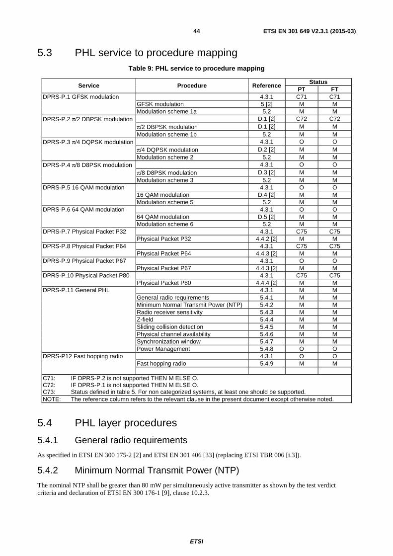
ETSI
ETSI EN 301 649 V2.3.1 (2015-03)44
5.3 PHL service to procedure mapping Table 9: PHL service to procedure mapping
Service Procedure Reference Status
PT FT DPRS-P.1 GFSK modulation 4.3.1 C71 C71 GFSK modulation 5 [2] M M Modulation scheme 1a 5.2 M M DPRS-P.2 π/2 DBPSK modulation D.1 [2] C72 C72 π/2 DBPSK modulation D.1 [2] M M Modulation scheme 1b 5.2 M M DPRS-P.3 π/4 DQPSK modulation 4.3.1 O O π/4 DQPSK modulation D.2 [2] M M Modulation scheme 2 5.2 M M DPRS-P.4 π/8 D8PSK modulation 4.3.1 O O π/8 D8PSK modulation D.3 [2] M M Modulation scheme 3 5.2 M M DPRS-P.5 16 QAM modulation 4.3.1 O O 16 QAM modulation D.4 [2] M M Modulation scheme 5 5.2 M M DPRS-P.6 64 QAM modulation 4.3.1 O O 64 QAM modulation D.5 [2] M M Modulation scheme 6 5.2 M M DPRS-P.7 Physical Packet P32 4.3.1 C75 C75 Physical Packet P32 4.4.2 [2] M M DPRS-P.8 Physical Packet P64 4.3.1 C75 C75 Physical Packet P64 4.4.3 [2] M M DPRS-P.9 Physical Packet P67 4.3.1 O O Physical Packet P67 4.4.3 [2] M M DPRS-P.10 Physical Packet P80 4.3.1 C75 C75 Physical Packet P80 4.4.4 [2] M M DPRS-P.11 General PHL 4.3.1 M M General radio requirements 5.4.1 M M Minimum Normal Transmit Power (NTP) 5.4.2 M M Radio receiver sensitivity 5.4.3 M M Z-field 5.4.4 M M Sliding collision detection 5.4.5 M M Physical channel availability 5.4.6 M M Synchronization window 5.4.7 M M Power Management 5.4.8 O O DPRS-P12 Fast hopping radio 4.3.1 O O Fast hopping radio 5.4.9 M M C71: IF DPRS-P.2 is not supported THEN M ELSE O. C72: IF DPRS-P.1 is not supported THEN M ELSE O. C73: Status defined in table 5. For non categorized systems, at least one should be supported. NOTE: The reference column refers to the relevant clause in the present document except otherwise noted.
5.4 PHL layer procedures
5.4.1 General radio requirements
As specified in ETSI EN 300 175-2 [2] and ETSI EN 301 406 [33] (replacing ETSI TBR 006 [i.3]).
5.4.2 Minimum Normal Transmit Power (NTP)
The nominal NTP shall be greater than 80 mW per simultaneously active transmitter as shown by the test verdict criteria and declaration of ETSI EN 300 176-1 [9], clause 10.2.3.

ETSI
ETSI EN 301 649 V2.3.1 (2015-03)45
5.4.3 Radio receiver sensitivity
The radio receiver sensitivity shall be -86 dBm, or better.
5.4.4 Z-field
The Z-field shall be transmitted by RFPs and PTs.
5.4.5 Sliding collision detection
PT and FT shall be able to detect sliding collision on received packets.
Minimum criteria for sliding collision are defined as S- or Z-field failure. Early sliding collision detection may be supported by other means e.g. signal strength measurements in the guard band.
The Z-field is defined to have failed if the received X- and Z-fields are not identical.
S-field failure is defined with some tolerance in order not to restrict the physical implementation of the word synchronization detector.
S-field failure may be indicated if there are 1 or more bit errors in bits s12 to s31 (errors in bits s0 to s11 shall be ignored). In all cases, S-field failure shall be indicated if 3 or more bit errors occur in bits s16 to s31.
5.4.6 Physical channel availability
A FP shall be able to receive and transmit on all DECT frequencies f0 to f9 and at least half of the slot pairs 0 to 11.
A PP shall be able to receive and transmit on all DECT frequencies f0 to f9, and shall be able to lock on any slot number 0 to 11, and receive and transmit at least on every slot pair that is not directly neighboured to the slot the PP is locked to, or to a slot on which a traffic bearer is active at the PP.
5.4.7 Synchronization window
Related to its reference timer, the PP synchronization window shall be at least ±4 bits for bearers to the RFP to which the reference timer is synchronized, and at least ±10 bits for other bearers.
5.4.8 Power management
To fight mutual interference between data terminals operating in different local DECT networks when using for the transmission most of the slots from a frame, control of the transmission power is recommended.
If transmission power control procedure is implemented, the requirements in ETSI EN 300 175-2 [2], annex E shall fully apply.
5.4.9 Fast hopping radio
The radio transceiver shall be able to perform any frequency change during the interval between two consecutive Physical Packets P32 (full slot) or P80 (double slot).
6 MAC layer requirements
6.1 MAC services Table 10: MAC service support for mobility class 1 and 2
Item Name of service Reference (note 1)
Support status PT FT
DPRS-M.1 General 4.3.2 M M DPRS-M.2 Non continuous broadcast 4.3.2 O O DPRS-M.3 Continuous broadcast 4.3.2 M M DPRS-M.4 Paging broadcast 4.3.2 M M DPRS-M.5 B-field Advanced connection control 4.3.2 M M

ETSI
ETSI EN 301 649 V2.3.1 (2015-03)46
Item Name of service Reference (note 1)
Support status PT FT
DPRS-M.6 IPM_error_detection 4.3.2 C104 C104
DPRS-M.7 IPMR_error_correction 4.3.2 O O
DPRS-M.8 U-plane point-to-multipoint service 4.3.2 O O DPRS-M.9 CS higher layer signalling 4.3.2 C101 C101
DPRS-M.10 CF higher layer signalling 4.3.2 C102 C102
DPRS-M.11 Encryption activation (GAP M.7) 4.3.2 M M DPRS-M.12 Encryption deactivation (GAP M.14) 4.3.2 C103 C103 DPRS-M.13 Quality control 4.3.2 M M DPRS-M.14 Physical channel selection 4.3.2 M M DPRS-M.15 SARI support 4.3.2 C101 C102 DPRS-M.16 DPRS Bearer handover 4.3.2 M M DPRS-M.17 Fast setup 4.3.2 O O DPRS-M.18 Connection handover 4.3.2 O O DPRS-M.19 GF channel 4.3.2 C107 C107
DPRS-M.20 IPQ_error_detection 4.3.2 C104 C104
DPRS-M.21 IPQR_error_correction 4.3.2 O O
DPRS-M.22 IPX_encoded protected 4.3.2 C105 C105
DPRS-M.23 IPF channel 4.3.2 C107 C107
DPRS-M.24 Full slot 4.3.2 C106 C106 DPRS-M.25 Long slot 640 4.3.2 C106 C106 DPRS-M.26 Long slot 672 4.3.2 C106 C106 DPRS-M.27 Double slot 4.3.2 C106 C106 DPRS-M.28 Multibearer connections 4.3.2 C107 C107 DPRS-M.29 Asymmetric connections 4.3.2 C108 C108 DPRS-M.30 Simplified A-field connection control 4.3.2 O O DPRS-M.31 Re-keying (GAP.M.15) 4.3.2 C109 C109 DPRS-M.32 Early encryption (GAP.M.16) 4.3.2 C110 C110 DPRS-M.33 AES/DSC2 encryption (GAP.M.17)
(see note 2) 4.3.2 O O
C101: IF DPRS-G1 (CLASS 1) THEN I ELSE M. C102: IF DPRS-G.1(CLASS 1) THEN I ELSE O. C103: IF DPRS-N.28 or DPRS-N.29 THEN M ELSE I. C104: Status depending on system category. See table 5. For non Categorized systems, at least
one should be supported. C105: IF 16 QAM or 64 QAM modulation THEN M ELSE O. C106: Status depending on system category. See table 5. For non Categorized systems, at least
one should be supported. C107: Status depending on system category. See table 5. For non Categorized systems: IF M.29
THEN M, ELSE O. C108: Status depending on system category. See table 5. For non Categorized systems THEN O. C109: IF DPRS-N.43 (GAP.N.35) and NWK layer procedure "Re-keying during a call" are
implemented THEN M ELSE O. C110: IF DPRS-N.43 (GAP.N.35) and NWK layer procedure "Early encryption" are implemented
THEN M ELSE O. NOTE 1: The reference column refers to the relevant clause in the present document. NOTE 2: IF implemented THEN DPRS-N.44 (GAP.N.36) shall be implemented.

ETSI
ETSI EN 301 649 V2.3.1 (2015-03)47
6.2 MAC service to procedure mapping Table 11: MAC service to procedure mapping
Service Procedure Reference (note 1)
Status PT FT
DPRS-M.1 General 4.3.2 M M Frame and Multiframe structure 10.1.1 M M Bit mappings 10.1.2 M M Scrambling 10.1.4 M M Error control 10.1.5 M M RFP idle receiver scan sequence 10.1.8 M M PT states and state transitions for PTs
not supporting fast setup 10.1.10.1 C1107 C1107
Identities 10.1.11 M M A-field Multiplexer (T-MUX) 10.21.1 M M B-field control Multiplexer (E/U-MUX),
basic modes 10.21.2.1 M M
DPRS-M.2 Non continuous broadcast 4.3.2 O O Request for specific Q channel
information 10.2.1 O O
Request for a new dummy 10.2.2 O O DPRS-M.3 Continuous broadcast 4.3.2 M M Downlink broadcast 10.3 M M DPRS-M.4 Paging broadcast 4.3.2 M M Paging messages 10.4.1 M M MAC layer information messages
procedures 10.4.2 M M
LCE paging procedure 10.4.3.1 M M MAC paging procedure 10.4.3.2.1 C1108 C1108 Paging detection: High duty cycle
(when there is an active virtual connection in suspend state)
10.4.4.2 C1109 C1109
Paging detection: High duty cycle (when there is no active virtual connection)
10.4.4.2 O M
Paging detection: Normal duty cycle (when there is an active virtual connection in suspend state)
10.4.4.1 C1110 C1110
Paging detection: Normal duty cycle (when there is no active virtual connection)
10.4.4.1 M M
Paging detection: Low duty cycle (when there is no active virtual connection)
10.4.4.3 O O

ETSI
ETSI EN 301 649 V2.3.1 (2015-03)48
Service Procedure Reference (note 1)
Status PT FT
DPRS-M.5 B-field Advanced connection control
4.3.2 M M Logical connection setup 10.5 M M
Logical connection release 10.6 M M Connection modification to change
bandwidth (including suspend) 10.7.1 M M
Connection modification to change MAC service type
10.7.2.1 O O
Connection modification to change slot type
10.7.2.2 O O
Connection modification to change modulation scheme or adaptive codec rate
10.7.2.3 O O
B-field Single bearer Physical connection setup
10.8.1 M M
B-field Physical Connection release 10.9 M M B-field Single duplex bearer setup 10.10.1 M M Usage of channel list messages 10.10.1.3 M M B-field Crossed bearer release 10.11.2 O O B-field Unacknowledged bearer
release 10.11.1 M M
B-field Acknowledged bearer release 10.11.3 O O DPRS-M.6 IPM_error_detection service
4.3.2 C104 C104 Type 3: IP_ error_detection symmetric MAC service
5.6.2.1 [3] M M
Type 7: IP_ error_detection
asymmetric MAC service 5.6.2.2 [3] C1101 C1101
Multi-subfield protected B-field 6.2.1.3.3 [3] M M Q1/Q2 bit setting for: IP_
error_detection 10.8.1.3.2 [3] M M
Protected I channel error_detect procedure
10.13.1 M M
DPRS-M.7 IPMR_error_correction service
4.3.2 O O Type 4: IP_ error_correction
symmetric MAC service 5.6.2.1 [3] M M
Type 8: IP_ error_correction
asymmetric MAC service 5.6.2.2 [3] C1101 C1101
Multi-subfield protected B-field 6.2.1.3.3 [3] M M MOD-2 protected channel operation 10.8.2 [3] M M Protected I channel error_correct
mode 10.13.2 M M
DPRS-M.8 U-plane point-to-multipoint service
4.3.2 O O Connectionless SIP mode 10.13.3 M M
DPRS-M.9 CS higher layer signalling 4.3.2 C101 C101
CS channel data 10.14.1 M M
DPRS-M.10 CF higher layer signalling 4.3.2 C102 C102
CF channel data 10.14.2 M M
B-field control Multiplexer (E/U-MUX), CF modes
10.21.2.2 M M
DPRS-M.11 Encryption activation (GAP M.7)
4.3.2 M M
Encryption process - initialization and synchronization
10.15.1 M M
Encryption mode control 10.15.2 M M Encryption handover control 10.15.3 M M DPRS-M.12 Encryption deactivation (GAP M.14)
4.3.2 C103 C103
Encryption mode control 10.15.2 M M

ETSI
ETSI EN 301 649 V2.3.1 (2015-03)49
Service Procedure Reference (note 1)
Status PT FT
DPRS-M.13 Quality control 4.3.2 M M RFPI handshake 10.16.1 M M PT frequency correction procedure 10.16.2 O O Bearer quality report 10.16.3 M M Bearer quality report for asymmetric
bearers (MAC-mod2-ACK) 10.16.3.1 C1101 C1101
Bearer and connection control 10.16.4 O O A-CRC handshake 10.16.5 M M DPRS-M.14 Physical channel selection
4.3.2 M M
Physical channel selection 10.17 M M DPRS-M.15 SARI support 4.3.2 C101 C102 Downlink broadcast 10.3.2.3 M M DPRS-M.16 DPRS Bearer handover 4.3.2 M M B-field MAC Bearer replacement
procedure 10.18 C1104 C1104
B-field MAC Bearer handover procedure
10.19 C1105 C1105
A-field MAC Bearer handover (MT) 10.23.4 C1106 C1106
DPRS-M.17 fast setup 4.3.2 O O FT initiated initial duplex bearer setup 10.10.1.3 M M PT receiver scan sequence 10.1.9 M M Fast setup control in MAC resume
and control page message 10.4.3.2.2 M O
PT states and state transitions for PTs supporting fast setup
10.1.10.2 M M
Listen for setup control codes in Release message
10.11.6 M M
DPRS-M.18 Connection handover 4.3.2 O O B-field Advanced connection
handover 10.12 C1104 C1104
A-field connection handover (MT) 10.23.4 C1106 C1106
DPRS-M.19 GF channel 4.3.2 C107 C107
GF channel transmission 10.20.1.1 O O
GF channel data reception 10.20.1.2 M M
DPRS-M.20 IPQ_error_detection service
4.3.2 C104 C104 Type 3: IP_ error_detection symmetric MAC service
5.6.2.1 [3] M M
Type 7: IP_ error_detection
asymmetric MAC service 5.6.2.2 [3] C1101 C1101
Single-subfield protected B-field 6.2.1.3.4 [3] M M Q1/Q2 bit setting for: IP_
error_detection 10.8.1.3.2 [3] M M
Protected I channel error_detect procedure
10.13.1 M M
DPRS-M.21 IPQR_error_correction service
4.3.2 O O Type 4: IP_ error_correction
symmetric MAC service 5.6.2.1 [3] M M
Type 8: IP_ error_correction
asymmetric MAC service 5.6.2.2 [3] C1101 C1101
Single-subfield protected B-field 6.2.1.3.4 [3] M M MOD-2 protected channel operation 10.8.2 [3] M M Protected I channel error_correct
mode 10.13.2 M M
DPRS-M.22 IPX_encoded protected 4.3.2 C105 C105
Type 5: IP_encodec protected
symmetric MAC service 5.6.2.1 [3] M M
Type 9: IP_encodec protected
asymmetric MAC service 5.6.2.2 [3] C1101 C1101
Channel coding clause I.1 [3] M M

ETSI
ETSI EN 301 649 V2.3.1 (2015-03)50
Service Procedure Reference (note 1)
Status PT FT
DPRS-M.23 IPF channel 4.3.2 C107 C107
B-field control Multiplexer (E/U mux), E+U mode
10.22.2.3 M M
IPF channel general 10.22.1 M M
IPF channel advanced procedures 10.22.2 O O
IPF channel error correct procedures 10.22.3 C1102 C1102
SIPF channel 10.22.4 C1103 C1103
DPRS-M.24 Full slot 4.3.2 C106 C106 D-field mapping for the full slot
structure (physical packet P32) 6.2.1.1.2 [3] M M
B-field mapping for the full slot structure (physical packet P32)
6.2.1.3.1.2 [3] M M
DPRS-M.25 Long slot 640 4.3.2 C106 C106 D-field mapping for the variable slot
structure (physical packet P00j) with j=640
6.2.1.1.4 [3] M M
B-field mapping for the half and long slot structure (physical packet P00j) with j=640
6.2.1.3.1.3 [3] M M
Additional procedures for Long and double slots
D.2 M M
DPRS-M.26 Long slot 672 4.3.2 C106 C106 D-field mapping for the variable slot
structure (physical packet P00j) with j=672
6.2.1.1.4 [3] M M
B-field mapping for the half and long slot structure (physical packet P00j) with j=672
6.2.1.3.1.3 [3] M M
Additional procedures for Long and double slots
D.2 M M
DPRS-M.27 Double slot 4.3.2 C106 C106 D-field mapping for the double slot
structure (physical packet P80) 6.2.1.1.1 [3] M M
B-field mapping for the double slot structure (physical packet P80)
6.2.1.3.1.1 [3] M M
Additional procedures for Long and double slots
D.2 M M
DPRS-M.28 Multibearer connections 4.3.2 C107 C107 Multi bearer Physical connection
setup 10.8.2 M M
MBC Multibearer control 5.2.4 [3] M M PT initiated additional duplex bearer
setup 10.10.1.4 M M
DPRS-M.29 Asymmetric connections 4.3.2 C108 C108 Double simplex bearers 5.5.1 [3] M M Asymmetric connections 5.6.2.2 [3] M M Double simplex bearer setup 10.10.2 M M Fast bearer release 10.11.3 M M Unacknowledged double simplex
bearer release 10.11.1 M M
Acknowledged double simplex bearer release
10.11.2 O O
DPRS-M.30 simplified A-field connection control
4.3.2 O O PT initiated A-field advanced bearer setup (MT)
10.23.2 M M
Connection/bearer release (MT) 10.23.3 M M
Connection modification to change MAC service type
10.7.2.1 O O
Connection modification to change slot type
10.7.2.2 O O
DPRS-M.31 Re-keying (GAP.M.15) 4.3.2 C109 C109 Re-keying 10.17 [11] M M

ETSI
ETSI EN 301 649 V2.3.1 (2015-03)51
Service Procedure Reference (note 1)
Status PT FT
DPRS-M.32 Early encryption (GAP.M.16)
4.3.2 C110 C110 Early encryption 10.18 [11] M M
DPRS-M.33 AES/DSC2 encryption (GAP.M.17) (see note 2)
O O O
AES/DSC2 encryption 10.19 [11] M M C101: IF DPRS-G1 (CLASS 1) THEN I ELSE M. C102: IF DPRS-G.1(CLASS 1) THEN I ELSE O. C103: IF DPRS-N.28 or DPRS-N.29 THEN M ELSE I. C104: Status depending on system category. See table 5. For non Categorized systems, at least one
should be supported. C105: IF 16 QAM or 64 QAM modulation THEN M ELSE O. C106: Status depending on system category. See table 5. For non Categorized systems, at least one
should be supported. C107: Status depending on system category. See table 5. For non Categorized systems: IF M.29 THEN
M, ELSE O. C108: Status depending on system category. See table 5. For non Categorized systems THEN O. C109: IF DPRS-N.43 (GAP.N.35) and NWK layer procedure "Re-keying during a call" are implemented
THEN M ELSE O. C110: IF DPRS-N.43 (GAP.N.35) and NWK layer procedure "Early encryption" are implemented THEN M
ELSE O. C1101: IF DPRS-M.29 THEN M ELSE I. C1102: IF DPRS-M.7 OR DPRS-M.21 THEN M ELSE I. C1103: IF DPRS-M.8 THEN O ELSE I. C1104: IF DPRS-M.5 THEN M ELSE I. C1105: IF DPRS-M.5 THEN O ELSE I. C1106: IF DPRS-M.30 THEN M ELSE I. C1107: IF DPRS-M.17 THEN I ELSE M. C1108: IF DPRS-G.1 (Class 1) OR DPRS-G.2 (Class 2) THEN M; IF DPRS-G.3 (Class 3) THEN O;
IF DPRS-G.4 (Class 4) THEN I. C1109: IF DPRS-G.1 (Class 1) OR DPRS-G.2 (Class 2) THEN M; IF DPRS-G.3 (Class 3) THEN O;
IF DPRS-G.4 (Class 4) THEN I. C1110: IF DPRS-G.1 (Class 1) OR DPRS-G.2 (Class 2) OR DPRS-G.3 (Class 3) THEN M; IF DPRS-G.4
(Class 4) THEN I. NOTE 1: The reference column refers to the relevant clause in the present or in the referenced document. NOTE 2: IF implemented THEN DPRS-N.44 (GAP.N.36) shall be implemented.

ETSI
ETSI EN 301 649 V2.3.1 (2015-03)52
7 DLC-layer requirements
7.1 DLC services Table 12: DLC service status
Item no. Name of service Reference Status
PT FT DPRS-D.1 LU10 Enhanced Frame RELay service (EFREL) 4.3.3 M M DPRS-D.2 FU10a 4.3.3 M M DPRS-D.3 FU10b 4.3.3 O O DPRS-D.4 FU10c 4.3.3 M M DPRS-D.5 Data Link Service (LAPC + Lc) class A service 4.3.3 M M DPRS-D.6 Data Link Service (LAPC + Lc) class U service 4.3.3 O O DPRS-D.7 Lc Frame delimiting and sequencing service 4.3.3 M M DPRS-D.8 Broadcast Lb service 4.3.3 M M DPRS-D.9 Inter-cell voluntary connection handover 4.3.3 O O DPRS-D.10 Connection modification 4.3.3 M M DPRS-D.11 Encryption activation (GAP D.6) 4.3.3 M C123 DPRS-D.12 Encryption deactivation (GAP D.9) 4.3.3 C121 C121 DPRS-D.13 Connectionless U-plane 4.3.3 C122 C122 C121: IF DPRS-N.28 or DPRS-N.29 THEN M ELSE I. C122: IF (Ethernet OR Token ring) THEN O ELSE I. C123: IF DPRS-N.17 (GAP.N.17) OR DPRS-N.27 (GAP.N.27) THEN M ELSE I. NOTE: The reference column refers to the relevant clause in the present document.
7.2 DLC feature to procedure mapping Table 13: DLC service to procedure mapping
Service Procedure Reference Status
PT FT DPRS-D.1 LU10 Enhanced Frame RELay service (EFREL)
4.3.3 M M U-plane transmission class 2 11.1.2 M M
DPRS-D.2 FU10a 4.3.3 M M FU10a frame operation 11.2.1 M M DPRS-D.3 FU10b 4.3.3 O O FU10b frame operation 11.2.2 M M DPRS-D.4 FU10c 4.3.3 M M FU10c frame operation 11.2.3 M M Insertion in FU10a frames of the opposite
link 11.2.3.1 M M
DPRS-D.5 Data Link Service (LAPC + Lc) class A service
4.3.3 M M Class A link establishment 11.3.1 M M
Class A acknowledged information transfer 11.3.2 M M Class A link release 11.3.3 M M Class A link re-establishment 11.3.4 M M DPRS-D.6 Data Link Service (LAPC + Lc) class U service
4.3.3 O O Class U use of LLN for unacknowledged information transfer
11.4.1 M M
Class U link establishment 11.4.2 M M Class U unacknowledged information
transfer 11.4.3 M M
Class U unacknowledged release 11.4.4 M M DPRS-D.7 Lc Frame delimiting and sequencing service
4.3.3 M M CS channel fragmentation and
recombination 11.5.1 M M
CF channel fragmentation and recombination
11.5.2 O O
Selection of logical channels (CS and CF) 11.5.3 M M

ETSI
ETSI EN 301 649 V2.3.1 (2015-03)53
Service Procedure Reference Status
PT FT DPRS-D.8 Broadcast Lb service 4.3.3 M M Normal operation 11.6.1 M M Expedited operation 11.6.2 C131 C131 DPRS-D.9 Inter-cell voluntary connection handover
4.3.3 O O Class A connection handover 11.7.1 M M
DPRS-D.10 Connection modification
4.3.3 M M Connection modification 11.8 M M
DPRS-D.11 Encryption activation (GAP D.6)
4.3.3 M M
Encryption switching 11.9 M M Connection handover of ciphered
connection 11.9.2.2 M C132
DPRS-D.12 Encryption deactivation (GAP D.9)
4.3.3 C121 C121
Encryption switching 11.9 M M DPRS-D.13 Connectionless U-plane
4.3.3 C122 C122 FU10a frame operation 11.2.1 M M
Connectionless point-to-multipoint transmission
11.10 M M
C121: IF DPRS-N.28 or DPRS-N.29 THEN M ELSE I. C122: IF (Ethernet OR Token ring) THEN O ELSE I. C131: IF DPRS-N.19 - fast paging implemented THEN M ELSE I. C132: IF DPRS-D.9 THEN M ELSE I. NOTE: The reference column refers to the relevant clause in the present document.
8 NWK layer requirements The NWK layer provisions shall include the following entities:
• Call Control (CC);
• Mobility Management (MM);
• Link Control Entity (LCE);
• Connectionless Message Service (CLMS).
Only mobility class 2 equipment requires a NWK layer. For mobility class 1 equipment configuration parameters shall be according to annex A of the present document.
NWK layer procedures shall be as defined in ETSI EN 300 444 [11] (GAP), in ETSI EN 300 824 [12] (CAP), or when relevant, in the present document.

ETSI
ETSI EN 301 649 V2.3.1 (2015-03)54
8.1 NWK features Table 14: NWK features status
Feature supported Features Status
Item no. Name of feature Reference PT FT DPRS-N.1 PT initiated virtual call 4.3.4 M M DPRS-N.2 Off hook 4.3.4 M M DPRS-N.3 On hook (full release) 4.3.4 M M DPRS-N.4 Dialled digits (basic) 4.3.4 O O DPRS-N.5 Register recall 4.3.4 O O DPRS-N.6 Go to DTMF signalling (defined tone length) 4.3.4 O O DPRS-N.7 Pause (dialling pause) 4.3.4 O O DPRS-N.8 FT initiated virtual call 4.3.4 O O DPRS-N.9 Authentication of PP (GAP N.9) 4.3.4 M C1401
DPRS-N.10 Authentication of user 4.3.4 O O DPRS-N.11 Location registration 4.3.4 M O DPRS-N.12 On air key allocation (GAP N.12) 4.3.4 M C1401 DPRS-N.13 Identification of PP 4.3.4 O O DPRS-N.14 Service class indication/assignment 4.3.4 O O DPRS-N.15 Alerting 4.3.4 O O DPRS-N.16 ZAP 4.3.4 O O DPRS-N.17 Encryption activation FT initiated (GAP N.17) 4.3.4 M C1401 DPRS-N.18 Subscription registration procedure on-air 4.3.4 M M DPRS-N.19 Link control 4.3.4 M M DPRS-N.20 Terminate access rights FT initiated 4.3.4 M O DPRS-N.21 Partial release 4.3.4 O O DPRS-N.22 Go to DTMF (infinite tone length) 4.3.4 O O DPRS-N.23 Go to Pulse 4.3.4 O O DPRS-N.24 Signalling of display characters 4.3.4 O O DPRS-N.25 Display control characters 4.3.4 O O DPRS-N.26 Authentication of FT (GAP N.26) 4.3.4 O O DPRS-N.27 Encryption activation PT initiated (GAP N.27) 4.3.4 O O DPRS-N.28 Encryption deactivation FT initiated (GAP N.28) 4.3.4 O O DPRS-N.29 Encryption deactivation PT initiated (GAP N.29) 4.3.4 O O DPRS-N.30 Calling Line Identification Presentation (CLIP) 4.3.4 O O DPRS-N.31 Internal call 4.3.4 O O DPRS-N.32 Service call 4.3.4 O O DPRS-N.33 Dynamic parameters allocation 4.3.4 M M DPRS-N.34 Service Negotiation at virtual call setup 4.3.4 M M DPRS-N.35 In call service change 4.3.4 O O DPRS-N.36 NWK layer management 4.3.4 M M DPRS-N.37 Identity assignment 4.3.4 O O DPRS-N.38 DECT External handover 4.3.4 O O DPRS-N.39 Message Waiting Indication 4.3.4 O O DPRS-N.40 Detach 4.3.4 O O DPRS-N.41 Periodic location registration 4.3.4 O O DPRS-N.42 On-air modification of user parameters 4.3.4 O O DPRS-N.43 Enhanced security (GAP.N.35) 4.3.4 O O DPRS-N.44 AES/DSAA2 authentication (GAP.N.36) 4.3.4 C1402 C1402
NOTE: The reference column refers to the relevant clause in the present document, except where stated otherwise.
C1401: IF DPRS-N.43 (GAP.N.35) THEN M ELSE O. C1402: IF DPRS-M.33 (GAP.M.17) THEN M ELSE O.

ETSI
ETSI EN 301 649 V2.3.1 (2015-03)55
8.2 NWK feature to procedure mapping Table 15: NWK feature to procedure mapping
Feature/Procedure mapping Status Feature Procedure Reference PT FT
DPRS-N.1, PT initiated virtual call 4.3.4 M M PT initiated virtual call request (outgoing
call) 12.1 M M
Overlap sending 8.3 [11] M O Outgoing call proceeding 8.4 [11] M O Outgoing call confirmation 8.5 [11] M O Outgoing call connection 8.6 [11] M M Sending keypad information 8.10 [11] O O DPRS-N.2, Off Hook 4.3.4 M M PT initiated virtual call request (outgoing
call) 12.1 M M
Incoming call connection 8.15 [11] M M DPRS-N.3, On Hook (full release) 4.3.4 M M Normal call release 8.7 [11] M M Abnormal call release 8.8 [11] M M DPRS-N.4, Dialled digits (basic) 4.3.4 O O Sending keypad information 8.10 [11] M M DPRS-N.5, Register recall 4.3.4 O O Sending keypad information 8.10 [11] M M DPRS-N.6 Go to DTMF signalling (defined tone length)
4.3.4 O O
Sending keypad information 8.10 [11] M M DPRS-N.7, Pause (dialling pause) 4.3.4 O O Sending keypad information 8.10 [11] M M DPRS-N.8, FT initiated virtual call 4.3.4 O O FT initiated virtual call request (incoming
call) 12.2 M M
Incoming call confirmation 8.13 [11] M M PT alerting 8.14 [11] M M Incoming call connection 8.15 [11] M M DPRS-N.9, Authentication of the PP (GAP N.9)
4.3.4 M C1509
Authentication of PP using DSAA 8.24 [11] M M Authentication of PP using DSAA2 8.45.7 [11] C1510 C1510 DPRS-N.10, Authentication of the user 4.3.4 O O Authentication of user using DSAA 8.25 [11] M M Authentication of user using DSAA2 8.45.8 [11] C1510 C1510 DPRS-N.11, Location registration 4.3.4 M O Location registration 8.28 [11] M M Location update 8.29 [11] M O Terminal capability indication 12.3 M M DPRS-N.12, On air key allocation (GAP N.12)
4.3.4 M C1509
Key allocation using DSAA 8.32 [11] M M Key allocation using DSAA2 8.45.9 [11] C1510 C1510 DPRS-N.13, Identification of PP 4.3.4 O O Identification of PT 8.22 [11] M M DPRS-N.14, Service class indication/assignment
4.3.4 O O Obtaining access rights 8.30 [11] M M
Terminal Capability indication 8.17 [11] O O Authentication of PP using DSAA 8.24 [11] M M Authentication of PP using DSAA2 8.45.7 [11] C1510 C1510 DPRS-N.15, Alerting 4.3.4 O O PT alerting 8.14 [11] M M DPRS-N.16, ZAP 4.3.4 O O Obtaining access rights [11] 8.30 [11] M M Terminal Capability indication 8.17 [11] O O Incrementing the ZAP value 8.26 [11] M M

ETSI
ETSI EN 301 649 V2.3.1 (2015-03)56
Feature/Procedure mapping Status Feature Procedure Reference PT FT
Authentication of FT using DSAA 8.23 [11] O M Authentication of FT using DSAA2 8.45.6 [11] C1511 C1510 DPRS-N.17, Encryption activation FT initiated (GAP N.17)
4.3.4 M M Cipher-switching initiated by FT using DSC 8.33 [11] M M
Cipher-switching initiated by FT using DSC2
8.45.10 [11] C1512 C1512
Storing the Derived Cipher Key (DCK) 8.27 [11] M M DPRS-N.18, Subscription registration user procedure on-air
4.3.4 M M Obtaining access rights 8.30 [11] M M
Terminal capability indication 12.3 M M DPRS-N.19, Link control 4.3.4 M M Indirect FT initiated link establishment, for
devices supporting complete MAC procedures. Initial setup paging
12.11.1.1 C1501 C1501
Indirect FT initiated link establishment, for devices supporting simplified (A-field) MAC procedures. Initial setup paging
12.11.2.1 C1502 C1502
Fast Paging 12.12 O O Collective and group ringing 12.13 O O Direct FT initiated link establishment 12.14 O O Direct PT initiated link establishment 8.36 [11] M M Link release "normal" [11] 8.37 [11] M M Link release "abnormal" 8.38 [11] M M Link release "maintain" 8.39 [11] I I Indirect FT initiated link establishment, for
devices supporting complete MAC procedures. LCE Resume Paging
12.11.1.2 C1501 C1503
Indirect FT initiated link establishment, for devices supporting simplified (A-field) MAC procedures. LCE Resume Paging
12.11.2.2 C1504 C1504
DPRS-N.20, Terminate access rights FT initiated
4.3.4 M O FT terminating access rights 8.31 [11] M M
Authentication of FT using DSAA 8.23 [11] O M Authentication of FT using DSAA2 8.45.6 [11] C1511 C1510 DPRS-N.21, Partial release 4.3.4 O O Partial release 8.9 [11] M M DPRS-N.22, Go to DTMF (infinite tone length)
4.3.4 O O Sending keypad information 8.10 [11] M M
DPRS-N.23, Go to Pulse 4.3.4 O O Sending keypad information 8.10 [11] M M DPRS-N.24, Signalling of display characters
4.3.4 O O Display 8.16 [11] M M
Terminal capability indication 12.3 M M DPRS-N.25, Display control characters 4.3.4 O O Display 8.16 [11] M M Terminal capability indication 12.3 M M DPRS-N.26, Authentication of FT (GAP N.26)
4.3.4 O O
Authentication of FT using DSAA 8.23 [11] M M Authentication of FT using DSAA2 8.45.6 [11] C1510 C1510 DPRS-N.27, Encryption activation PT initiated (GAP N.27)
4.3.4 O O Cipher-switching initiated by PT using DSC 12.9 M M
Cipher-switching initiated by PT using DSC2
8.45.11 [11] C1512 C1512
Storing the DCK 8.27 [11] M M DPRS-N.28, Encryption deactivation FT initiated (GAP N.28)
[11] 4.3.4 O O
Cipher-switching initiated by FT using DSC 8.33 [11] M M Cipher-switching initiated by FT using
DSC2 8.45.10 [11] C1512 C1512

ETSI
ETSI EN 301 649 V2.3.1 (2015-03)57
Feature/Procedure mapping Status Feature Procedure Reference PT FT
DPRS-N.29, Encryption deactivation PT initiated (GAP N.29)
4.3.4 O O Cipher-switching initiated by PT using DSC 12.9 M M
Cipher-switching initiated by PT using DSC2
8.45.11 [11] C1512 C1512
DPRS-N.30, Calling Line Identification Presentation (CLIP)
4.3.4 O O FT initiated virtual call request (incoming call)
12.2 M M
DPRS-N.31, Internal call 4.3.4 O O Internal call setup 8.18 [11] M M Internal call keypad 12.4 O O DPRS-N.32, Service call 4.3.4 O O Service call setup 8.20 [11] M M Service call keypad 8.21 [11] O O DPRS-N.33, Dynamic parameters allocation
4.3.4 M M General requirements 12.8.1 M M Sent IE and Default IE Dynamic Parameter Allocation
12.8.2 M M
Transport of the <<SETUP CAPABILITY>> IE (when used)
12.8.3 M M
Service and parameter settings support indication (PT or FT)
12.8.4 M M
Application media protocol support indication (PT and FT)
12.8.5 C1516 C1516
Allowed and mandatory values for the DPRS Class 2 PT and FT devices
12.8.6 C1517 C1517
Allowed values for DPRS Class 3 and 4 P [11] T and FT devices
12.8.7 C1518 C1518
Transport with {MM-INFO-SUGGEST} message (FT to PT)
12.8.8 C1517 C1517
Transport with {CLMS-FIXED} message (FT to PT)
12.8.9 C1517 C1517
Class 2 Default Dynamic Parameters Allocation for PT and FT devices
12.8.10 C1517 C1517
Default setup attributes for basic service "light data service, with Class 4 DPRS management" (code "1001"B)
A.2.1 C1519 C1519
Default setup attributes for basic service "light data service with Class 3 DPRS management" (code "1010"B)
A.2.2 C1520 C1520
DPRS-N.34, Service Negotiation at virtual call setup
4.3.4 M M
General requirements 12.5.1 M M Allowable values on initiating side 12.5.2 M M Negotiation process 12.5.3 M M Allowable values in the answer 12.5.4 M M Default values for class 2 on initiating side 12.5.5 M M Exceptional cases 12.5.6 M M IP address allocation (IP IWU only) 12.5.7 C1505 C1505 DPRS-N.35, In call service change 4.3.4 O O Service change - Bandwidth Change 12.6.1 M M Slot type change 12.6.2 O O MAC Service change 12.6.3 O O Modulation type or adaptive codec rate
change 12.6.4 O O
DPRS Management Entity Class and other Call-attributes change
12.6.5 O O
MAC Packet lifetime, DLC Window size, DLC Transit delay and CF channel
attributes change
12.6.6 O O
IWU-attributes change - General 12.7.1 M M Interworking type change 12.7.2 C1506 C1506 IP address change (IP IWU) 12.7.3 C1505 C1505 Maximum SDU size change 12.7.4 O O

ETSI
ETSI EN 301 649 V2.3.1 (2015-03)58
Feature/Procedure mapping Status Feature Procedure Reference PT FT
DPRS-N.36, NWK layer management 4.3.4 M M Management of MM procedures 12.18 M M Management - Location registration
initiation 13.2 [11] M C1507
Management - Assigned individual TPUI 13.3 [11] M C1507 Management - PMID 12.19 M M Management - DCK 13.6 [11] M M Management - Broadcast attributes 12.16, 12.17
[11] M M
Management - Storage of subscription related data
13.7 [11] M M
U-plane handling 12.17 M M Length of NWK layer messages 12.20 M M Identities 12.21 M M DPRS-N.37, Identity Assignment 4.3.4 O O Temporary Identity Assign 12.10 M M DPRS-N.38, DECT External handover 4.3.4 O O Handover candidate indication 9.1.1.1 [12] M M Handover candidate retrieval 9.1.1.2 [12] M O Target FP selection 9.1.2 [12] M N/A Handover reference indication 9.1.3.1 [12] M C1508 Handover reference retrieval 9.1.3.2 [12] M C1508 External handover call setup 9.1.4 [12] M M Ciphering procedure PT initiated 9.1.5.1 [12] O O Ciphering procedure FT initiated 9.1.5.2 [12] M M U-plane handling 9.1.6 [12] M M DPRS-N.39, Message Waiting Indication 4.3.4 O O Message waiting indication 9.7 [12] M M DPRS-N.40, Detach 4.3.4 O O Detach 9.5 [12] M M DPRS-N.41, Periodic location registration 4.3.4 O O Enhanced location registration 9.6 [12] M M DPRS-N.42, On-air modification of user parameters
4.3.4 O O On-air modification of user parameters 9.8 [12] M M
FT authentication 8.23 [12] M M DPRS-N.43, Enhanced security (GAP.N.35)
4.3.4 O O
Encryption of all calls 8.45.1 [11] M M Re-keying during a call 8.45.2 [11] O O Early encryption 8.45.3 [11] O O Subscription requirements 8.45.4 [11] M M Behaviour against legacy devices 8.45.5 [11] M M

ETSI
ETSI EN 301 649 V2.3.1 (2015-03)59
Feature/Procedure mapping Status Feature Procedure Reference PT FT
DPRS-N.44, AES/DSAA2 authentication (GAP.N.36)
4.3.4 C1513 C1513
Authentication of FT using DSAA2 (see [12] note)
8.45.6 [11] O O
Authentication of PP using DSAA2 8.45.7 [11] M M Authentication of user using DSAA2 8.45.8 [11] M M Key allocation using DSAA2 8.45.9 [11] M M Cipher-switching initiated by FT using
DSC2 8.45.10 [11] C1514 C1514
Cipher-switching initiated by PT using DSC2
8.45.11 [11] C1515 C1515
C1501: IF DPRS-M.5 THEN M ELSE I. C1502: IF DPRS-M.30 THEN (IF DPRS-N.8 OR DPRS-ME.1 THEN M ELSE O) ELSE I. C1503: IF DPRS-M.5 THEN (IF single cluster system THEN O ELSE M) ELSE I. C1504: IF DPRS-M.30 AND DPRS ME.3 THEN M ELSE I. C1505: IF Interworking type Internet Protocol THEN O ELSE I. C1506: IF several Interworking types implemented THEN O ELSE I. C1507: IF DPRS-N.11 THEN M ELSE I. C1508: At least one of these procedures shall be supported. C1509: IF DPRS-N43 (GAP.N.35) THEN M ELSE O. C1510: IF DPRS-N44 (GAP.N.36) THEN M ELSE I. C1511: IF DPRS-N44 (GAP.N.36) THEN O ELSE I. C1512: IF DPRS-N44 (GAP.N.36) and DPRS-M.33 (GAP.M.17) THEN M ELSE I. C1513: IF DPRS-M.33 (GAP.M.17) THEN M ELSE O. C1514: IF DPRS-M.33 (GAP.M.17) THEN M ELSE I. C1515: IF DPRS-N.28 (GAP.N.27) or DPRS-N.29 (GAP.N.29) and DPRS-M.33 (GAP.M.17) THEN M ELSE I. C1516: IF B.8 supported THEN M ELSE I. C1517: IF DPRS-ME.2 THEN M ELSE I [11]. C1518: IF DPRS-ME.3 OR DPRS-ME.4 OR BOTH THEN M ELSE I. C1519: IF DPRS-ME.4 THEN M ELSE I. C1520: IF DPRS-ME.3 THEN M ELSE I. NOTE: The reference column refers to the relevant clause in the present document, except where stated
otherwise.
8.3 Application features Table 16: Application features status
Feature supported Status Item no. Name of feature Reference PT FT
DPRS-A.1 AC_bitstring_mapping 4.3.5 M M DPRS-A.2 Multiple subscription registration 4.3.5 O N/A DPRS-A.3 Manual entry of the PARK 4.3.5 O N/A NOTE: The reference column refers to the relevant clause in the present document.
8.4 Application feature to procedure mapping Table 17: Application feature to procedure mapping
Feature/Procedure mapping Status Feature Procedure Reference PT FT
DPRS-A.1, AC to bitstring mapping 4.3.5 M M AC to bitstring mapping 14.2 [11] M M DPRS-A.2, Multiple subscription registration 4.3.5 O N/A Subscription control 14.1 [11] M N/A DPRS-A.3, Manual entry of the PARK 4.3.5 O N/A Manual entry of the PARK 14.3 [11] M N/A NOTE: The reference column refers to the relevant clause in the present document, except where stated
otherwise.

ETSI
ETSI EN 301 649 V2.3.1 (2015-03)60
8.5 Distributed Communications
8.5.1 Distributed Communications features
Table 18: Distributed Communications feature status
Feature supported Status Item no. Name of feature Reference PT FT HyP
DPRS-DC.1 Distributed Communications 4.3.6 O O M NOTE: The reference column refers to the relevant clause in the present document.
8.6 Distributed Communications feature to procedure mapping Table 19: Distributed Communication feature to procedure mapping
Feature/Procedure mapping Feature/Procedure Status
Feature Name Procedure name Reference PT FT HyP DPRS-DC.1 4.3.6 O O M General Requirements 13.2 M M M HyP Identities handling 13.3.1 N/A M M Membership Access Rights Allocation 13.3.2 M M M Re-initialization of membership access rights 13.3.3 M M M Members Data Transfer 13.3.4 M M M Presence/Absence Indication 13.3.5 M M M Bandwidth management 13.3.6 M M M Direct Link Establishment 13.3.7 M M M Indirect Link Establishment 13.3.8 M M M MASTER management 13.3.9 M M M Common Subscription Database management 13.3.10 M M M Handover issues 13.3.11 M M M Usage of PPs or FPs in DCDL-net 13.5 M M M NOTE: The reference column refers to the relevant clause in the present document.
9 Management Entity Requirements
9.1 Introduction The Management Entity (ME) is responsible for management of physical resources and logical associations between and into the DECT protocol layers.
9.1.1 Management Entity (ME) operation modes
DPRS provides four operation modes of the Management Entity (ME): Class 1, Class 2, Class 3 and Class 4.
• ME Class 1 provides complete MAC connection control (including multibearer and asymmetric connections), packet handling, but it does not include NWK layer C-plane (no call control or mobility management procedures). The service provided by ME Class 1, called is equivalent to a Wireless LAN.
• ME Class 2 provides complete DPRS functionalities, including complete MAC connection control, optimized packed handing functionalities and complete NWK layer C-plane with call control and mobility management functionalities. The service provided by Class 2 is equivalent to the packet service of a cellular system with efficient packet handling.
• ME Class 3 provides a simplified management mode for single bearer DPRS connections. It is optimized for the data needs of voice terminals or other limited rate data devices. Applications include software downloading, limited content browsing such as agenda browsing, SMS handling or configuration facilities. Provides simplified mechanisms for connection management and limited support of suspend/resume and it incorporates NWK layer C-plane.

ETSI
ETSI EN 301 649 V2.3.1 (2015-03)61
• ME Class 4 provides a simplified management mode for single bearer DPRS connections. It is optimized for the data needs of voice terminals or other limited rate data devices. Applications include software downloading, limited content browsing such as agenda browsing, SMS handling or configuration facilities. Provides simplified mechanisms for connection management and it incorporates NWK layer C-plane. It does not support suspend/resume.
Table 20: Management Entity operation mode status
Feature supported Status Service Name of feature Reference PT FT
DPRS-ME.1 Class 1 management 4.3.7 C201 C201 DPRS-ME.2 Class 2 management 4.3.7 C202 C202 DPRS-ME.3 Class 3 management 4.3.7 O O DPRS-ME.4 Class 4 management 4.3.7 O O C201: IF DPRS CC and MM Service Class 1 supported [DPRS-G.1] THEN M ELSE I. C202: IF DPRS CC and MM Service Class 2 supported [DPRS-G.2] THEN M ELSE I.
9.1.2 Management Entity (ME) mode to procedures mapping
Table 21: Management Entity mode to procedures mapping
Feature/Procedure mapping Status Service Procedure Reference PT FT
DPRS-ME.1, Class 1 management 4.3.7 C201 C201 Logical Connection management 9.4.1, 9.2.2 M M Suspend management 9.3.1.2,
9.3.2.2 M M
Resume management 9.3.1.1.2, 9.3.2.1
M M
Dynamic Bandwidth management 9.3.1.4, 9.3.2.3
C211 C211
DPRS-ME.2, Class 2 management 4.3.7 C202 C202 Logical Connection management 9.4.2, 9.2.3 M M Suspend management 9.3.1.2,
9.3.2.2 M M
Resume management 9.3.1.1.2, 9.3.2.1
M M
Stay Alive 9.4.2.5 M M Dynamic Bandwidth management 9.3.1.4,
9.3.2.3 C211 C211
DPRS-ME.3, Class 3 management 4.3.7 O O Simplified Class 3 connection management 9.5.1 M M Suspend management (Tx side) 9.5.2 O O Suspend management (Rx side) 9.5.3 M M Resume management 9.5.4 M M Stay alive (timer control) 9.5.5 M M Stay alive (periodic resume) 9.5.6 C212 C212 Logical connection management for service
Class 3 9.4.3, 9.2.4 M M
DPRS-ME.4, Class 4 management 4.3.7 O O Simplified Class 4 connection management 9.5.7 M M Logical connection management for service
Class 4 9.2.5 M M
C201: IF DPRS CC and MM Service Class 1 supported [DPRS-G.1] THEN M ELSE I. C202: IF DPRS CC and MM Service Class 2 supported [DPRS-G.2] THEN M ELSE I. C211: IF (DPRS-M.5. Multi bearer Physical connection setup) THEN M ELSE I. C212: IF Suspend management (Tx side) THEN M ELSE O. NOTE: The reference column refers to the relevant clause in the present document.

ETSI
ETSI EN 301 649 V2.3.1 (2015-03)62
9.2 Description of the DPRS operation principles
9.2.1 General
In DPRS, the management of the "physical connections" is always under control of the Management Entity (ME). The ME decides in real time the activation, release, or change of bandwidth of the physical connection, based on the existence of U-plane data or C-plane messages to be transmitted, and according to the requirements described in this clause. The higher layer entities are responsible for the presence or absence of the valid data at the MAC service boundaries upon which such lower layer resource management is based.
9.2.2 Service class 1
Service class 1 is a simplified version of DPRS that does not incorporate C-plane. Class 1 is intended for small private applications with restricted mobility and control features. Because of back-compatibility reasons, class 1 uses a specific ad-hoc solution with some differences with class 2 equipment.
In service class 1, the "physical connection", the MBC instance, and the DLC link, are permanently associated. The activation and release of the physical resources are done by setup and release of the DLC "link". All requirements provided in this clause are valid, taken into account that the activation or release of a "physical connection" has associated the activation or release of the MBC and DLC layers.
Service class 1 provides a user service that is equivalent to a Permanent Virtual Circuit (PVC).
9.2.3 Service class 2
Service class 2 provides additionally the capabilities of the DECT C-plane. In service class 2, any NWK layer service is permanently mapped to a DLC layer "link" and to a MBC logical instance called "logical connection". All these entities exist during the length of a user connection. User connections could be "Virtual Calls" (VC) or "Permanent Virtual Circuits" (PVC).
NOTE: A DPRS virtual call is identical to what in GPRS is called "PDP context". A PVC is a particular case of virtual call permanently connected by configuration.
It is possible to having multiple data contexts (virtual calls) in the cell and between each PT-FT pair. Each "virtual call" behaves as a connection oriented pipe transporting the user protocol. Security (authentication and encryption) and mobility management operations (i.e. handovers) are performed by the DECT system and higher layer application does not need to worry on them.
The service provided by Class 2 management is equivalent to the packet service of a cellular system.
The allocation of physical resources to the "logical connection" is performed in real time by the Management Entity, based on the existence of U-plane data or C-plane messages to be transmitted, and according to the requirements described in this clause. The set of bearers and TBCs temporally allocated to a "logical connection" is the "physical connection".
A "logical connection" is in active state if it has associated a "physical connection" and in suspended state otherwise.
Class 2 management includes the capability of dynamic parameters broadcast or negotiation that allows to refine the packet handling efficiency.
9.2.4 Service class 3
Service class 3 provides a simplified management mode for single bearer DPRS connections. It is optimized for the data needs of voice terminals or other limited rate data devices. Applications include software downloading, limited content browsing such as agenda browsing, SMS handling or configuration facilities. Class 3 provides NWK layer C-plane, limited support of suspend/resume, call control and mobility management, however the ME operation is largely simplified.

ETSI
ETSI EN 301 649 V2.3.1 (2015-03)63
9.2.5 Service class 4
Service class 4 provides a simplified management mode for single bearer DPRS connections. It is optimized for the data needs of voice terminals or other limited rate data devices. Applications include software downloading, limited content browsing such as agenda browsing, SMS handling or configuration facilities. Class 4 provides NWK layer C-plane, call control and mobility management, however it does not support suspend/resume.
9.3 Resource and physical connection management for Class 1 and Class 2 systems
This clause describes when a "Physical Connection" should be setup or released, and which procedures should be used for Class 1 and Class 2 systems.
For Class 3 and Class 4 devices refer to clause 9.5.
9.3.1 Requirements applicable to the Fixed Part (FP)
9.3.1.1 Conditions for resumption and management procedures
9.3.1.1.1 General
The FT may resume a Physical Connection, if any of the following conditions meet:
• there are user plane data to be transmitted downstream;
• there are high layer C-plane data to be transmitted downstream (applicable only to service class 2);
• there are MAC control messages to be transmitted downstream;
• the PT was suspended by the FT due to bandwidth administration reasons having data to be transmitted upstream;
• the PT has attempted to resume the connection with the result of being rejected by the FT.
NOTE: The activation of the Physical Connection as consequence of the handshake procedure is considered as part of condition 3 (see clause 9.4.3).
9.3.1.1.2 ME procedures for FT initiated connection resumption
For equipment of both mobility class 1 and mobility class 2, MAC connection establishment from the FT to the PT goes as follows.
9.3.1.1.2.1 Fast setup ME procedure
The FT shall try to establish the Physical Connection using the FT initiated setup procedure (fast setup) (see clause 10.10.1.3) if the FT supports Fast Setup, and the PT supports fast setup and is supposed to be in idle-locked state with setup detection.
• The PT will be supposed to be in idle-locked state with setup detection if the time elapsed since the Physical Connection was released by last time is lower than timer T909.
The fast setup procedure should result in at least one setup attempt. If the PT is supposed not to be in idle-locked state with setup detection, then the fast setup is not required.
9.3.1.1.2.2 MAC paging ME procedure
If Fast setup procedure not been used, then the FT shall try to establish the Physical Connection using MAC-resume paging procedure (see clauses 9.3.1.1.2.2 and 10.4).
If Fast setup procedure has been used and has failed, then the FT may try to establish the Physical Connection using MAC-resume paging procedure, or may skip this step, and use directly LCE-paging.
The MAC resume paging shall be done according to clause 10.4.

ETSI
ETSI EN 301 649 V2.3.1 (2015-03)64
The FT may take into account the time elapsed since last suspension and the value of timer T911 (and T909 if fast setup is supported) in order to determine is the PT is in high duty cycle paging detection, or in normal paging detection (see clause 9.3.1.2.5).
If the FT has performed the previous check:
• The FT shall send the MAC resume paging request in a frame recognized by the PT.
• If the procedure fails, the FT is free to repeat the MAC paging attempt, wait for the normal duty cycle window, or start directly the LCE paging procedure.
If the FT has not performed the previous check (the FT does not know in which state the PT is):
• The FT may act as if the PT were in high duty cycle paging detection performing a maximum of two MAC-resume paging attempts.
• If they fail, the FT shall wait for the next normal duty cycle window and shall perform a normal MAC paging attempt.
• Only if previous attempt fails, the FT could initiate the LCE-paging procedure (normal duty cycle window). The FT is also allowed to repeat the MAC paging procedure (normal duty cycle window).
• FTPT.
NOTE: MAC paging is not required if the FT has done a Fast Setup attempt and Fast Setup is supported by the PT.
9.3.1.1.2.3 LCE paging ME procedure
If the previous setup procedures have failed, the FT shall try to establish the Physical Connection using LCE-resume paging (see clause 12.15). The FT shall use fast LCE-resume paging, if the FT knows that the PT is in high duty cycle paging detectionPT.
Otherwise (if the FT knows that the PT is in normal duty cycle state, or if it does not know in which state the PT is) the FT shall use normal LCE-resume paging.
If fast LCE-paging has been used and has failed, the FT shall try to establish a Physical Connection with normal LCE-resume paging.
• The FT may freely choose the number of fast LCE-paging attempts before trying normal LCE-paging.
The LCE resume paging procedure shall be done according to the procedure described in clause 12.15.
In case of no response from the PT, the FT may repeat the paging attempt according to implementation specific algorithms. Process may continue until violation of the handshake (stay alive) procedure (see clause 9.4.3), when the connection shall be released.
9.3.1.1.2.4 Class 1 systems
Class 1 systems
For class 1 systems, the paging shall be initiated by the ME, by issuing a MAC_PAGE-req primitive. The SDU passed with the primitive shall be such that the content of the paging message is as defined in ETSI EN 300 175-5 [5], clause 8.2.1, short format message, using default TPUI, with the following exception:
• the LCE header field shall have the value 111 (IP_error_correct) or 110 (IP_error_detect).
Receipt of a paging message with a mobility class 1 TPUI indicates that the paging message should be handled by the ME. Upon receipt of a MAC-PAGE-ind primitive with the TPUI of the PT as parameter, the ME shall issue a MAC_CON-req primitive.

ETSI
ETSI EN 301 649 V2.3.1 (2015-03)65
9.3.1.2 Connection Suspension conditions
9.3.1.2.1 General
The ME of the FT may request a suspension of the connection at any time according to implementation specific algorithms.
In addition to that, the FT shall request a suspension of the connection in the following cases:
• in case of no user-data or C-plane activity;
• by violation of the minimum number of bearers (MAC Bandwidth command);
• by loss of all received bearers;
• by loss of the last duplex bearer controlling the connection.
The FT shall indicate the relevant Suspension reason as indicated in clause 10.7.1.3.
If the FT indicates for suspension reason the < Local temporary transmission/reception limits > or <bandwidth administration> or any other reason but has set the flag -f (see clause 10.7.1.3), THEN, the PT shall accept the suspension even if there is a data for transmission up-link.
In all other cases, if there is data for transmission up-link, or if the FT has used the flag -s, the PT may reject the suspension, see clause 10.7.1.
In any case, the FT is allowed to force the PT down to the minimum number of bearers, negotiated by the NWK layer.
NOTE: Under "number of bearers" throughout the present document, the number of simplex bearers in one direction is to be understood, e.g. a double simplex bearer consist of 2 simplex bearers, whereas, a duplex bearer consist of 1 uplink and 1 down-link simplex bearers.
9.3.1.2.2 Connection suspension due to no data activity
The ME of the FT shall request a suspension of the connection if no new PDU or C-plane message has been transmitted nor received during an internal timer (FT suspend timer) indicating suspension reason < No data for transmission >.
The value of the internal FT suspend timer is not standardized, and can vary dynamically.
NOTE 1: However, it is recommended to make this timer equal to T903.
See clause 10.7.1 for the suspend procedure.
NOTE 2: Timer T903 is set by the FT (see annex A).
9.3.1.2.3 Connection suspension due to violation of the minimum number of bearers (MAC Bandwidth command)
The FT shall suspend the connection if the MAC layer is unable to set the "minimum number of bearers" for any of the directions of the connection, and this situation exists for more time than T906 indicating suspension reason < Violation of the minimum number of bearers >. See clause 10.7.1 for the suspend procedure.
NOTE: See annex A for definition and value of T906.
The FT may suspend the connection if it receives from the PT a Bandwidth request message with values out of the range negotiated at NWK layer.
9.3.1.2.4 Connection suspension by loss of all received bearers
The FT will suspend the connection if all received bearers of the connection are lost, and this situation exists for more time than T908.
NOTE: See annex A for definition and value of T908.

ETSI
ETSI EN 301 649 V2.3.1 (2015-03)66
9.3.1.2.5 Activation of Fast Scan mode and/or high duty cycle paging detection after Connection suspension
After the suspension of the connection, if the PT supports fast setup, and parameter T909 (see annex A) (class 2 devices) is different from zero, the PT shall pass to Idle-locked state with setup detection (fast scan mode), as defined in ETSI EN 300 175-3 [3], clause 11.3.3.2.
The PT shall remain in this state for at least the time specified in the parameter T909 During this time, the PT shall accept FT initiated bearer setup using the procedure defined in clause 10.10.1.2. After this time the PT may pass to normal Idle-locked state with page detection (ETSI EN 300 175-3 [3], clause 11.3.3.1).
For service class 1 equipment the value of T909 is stored in the PT configuration table (see clause A.1.2).
For service class 2 equipment, T909 is variable parameter (see clause A.1.3.2) that can be negotiated between FT and PT by means of the << SETUP-CAPABILITY >> NWK layer information element (see clause 12.8).
If the PT does not support fast setup, the timer T909 has been set to zero, or the timer has expired, then, the PT shall pass to Idle-locked state with high duty cycle paging detection.
The PT shall remain in this state the time indicated by timer T911.
After the expiration of timer T911, the PT shall pass to Idle-locked state with normal duty cycle paging detection.
The value zero of timer T911 means that the PT shall pass directly to normal duty cycle paging detection.
NOTE: It is not allowed to use slow duty cycle paging detection when in suspend state.
If a connection is resumed and immediately suspended as consequence only of the stay alive procedure (see clause 9.4.3), the timers T909 and T911 shall not be reset, and the PT shall continue in the detection mode determined by the timers.
9.3.1.3 Conditions for Bandwidth modification
9.3.1.3.1 General
The ME of the FT could decide a change in the bandwidth of a connection at any time according to implementation specific algorithms. The FT will use the Bandwidth modification procedure described in clause 10.7.
The PT shall mandatory accept any change of Bandwidth instanced by the FT if the requested bandwidth is within the maximum and minimum values negotiated at NWK layer.
9.3.2 Requirements applicable to the Portable Part (PP)
9.3.2.1 Conditions for connection resumption
The Connection will be resumed by the PT if and only if any of the following conditions meet:
• the PT has U-plane data ready to be sent upstream;
• the PT has C-plane data ready to be sent upstream;
• the PT has MAC control messages to be transmitted upstream;
• the PT initiated this procedure with the result of being refused by the FT, as described in clause 9.3.2.1.5, and a time equal to WtB ("Waiting time B"), defined in annex A, has elapsed.
NOTE: The resumption of the Physical Connection as consequence of the handshake procedure is considered as part of condition 3.
If the connection was previously suspended by the FT, (see clause 9.3.1.2.1), the PT shall not request a connection resume during an interval equal to WtB ("Waiting time B") as defined in annex A.
9.3.2.1.1 Procedure for PT initiated Connection resumption
The sequence of procedures for the resumption of a connection shall consist on PT initiated pilot bearer setup (see clause 10.10) followed by connection modification (see clause 10.7).

ETSI
ETSI EN 301 649 V2.3.1 (2015-03)67
9.3.2.1.2 "RFP-busy-for-data" flag
The PT shall not initiate the PT initiated connection resumption procedure if the RFP has activated the RFP-busy-for-data flag in RFP status (ETSI EN 300 175-3 [3], clause 7.2.4.3.9).
9.3.2.1.3 Waiting time for collision avoidance after deactivation of "RFP-busy-for-data" flag
If the RFP had activated the RFP-busy-for-data flag in RFP status (ETSI EN 300 175-3 [3], clause 7.2.4.3.9), after the deactivation of this flag, the PT shall wait a random interval WtA (see clause A.1.2.1) before initiating any bearer setup procedure, to prevent access collisions. In case of access collision during the following PT initiated setup procedure (see clause 10.10.1.2), the PT shall wait a random interval WtA before repeating the access request attempt. In case of successive collisions, formula will be applied with successive increment in the spreading range.
9.3.2.1.4 Bandwidth after resumption
As consequence of the procedure, the FT will inform the PT about the number of bearers (bandwidth) to be used. This value shall be within the range negotiated by the network layer. The PT will use always the bandwidth mandated by the FT.
9.3.2.1.5 Resumption rejection by the FT
If as consequence of the setup procedure, the FT rejects the access attempt with the message Bandwidth = zero, the PT will do the following actions:
• PT shall immediately release all bearers;
• PT shall wait the waiting time WtB (see clause A.1.2.2) and shall repeat the pilot bearer setup procedure (see clause 10.10.1.2).
In case of repetitive failures the waiting time WtB shall be increased to obtain congestion avoidance, according to the formulae given in annex A.
NOTE: During the time the PT is waiting the waiting time WtB, there exists the possibility that the FT may initiate the resume of the connection. A good implementation of the FP ME should do that if the conditions that justified the access rejection (i.e. congestion) end before the completion of WtB. However, the PT keeps the timer running until its expiration, since it also applies to bandwidth expansion requests (see clause 9.3.2.3.1). The PT cannot request bandwidth expansion until termination of the timer.
9.3.2.2 Conditions for Connection Suspension
9.3.2.2.1 General
The ME of the PT may request a suspension of the Connection at any time according to implementation specific algorithms.
In addition to that, the PT shall initiate a suspension of the Connection in the following cases:
• in case of no user-data or C-plane activity;
• by violation of the minimum number of bearers (MAC Bandwidth command);
• by loss of all received bearers;
• by loss of the last duplex bearer controlling the connection.
The PT shall indicate the relevant Suspension reason as indicated in clause 10.7.1. If the PT indicates for suspension reason the < Local temporary transmission/reception limits > and the minimum number of bearers negotiated by the NWK layer was "0" the FT shall accept the suspension even if there is a data for transmission down-link. In all other cases, if there is data for transmission downlink, the FT may reject the suspension, see clause 10.7.1.
9.3.2.2.2 Connection suspension due to no data activity
The ME of the PT shall request a suspension of the connection if no new PDU or C-plane message has been transmitted nor received during a consecutive period of T903 indicating suspension reason < No data for transmission >. See clause 10.7.1 for suspend procedure.

ETSI
ETSI EN 301 649 V2.3.1 (2015-03)68
NOTE: Timer T903 is broadcasted by the FP (see annex A).
9.3.2.2.3 Connection suspension due to violation of the minimum number of bearers (MAC Bandwidth command)
The PT shall suspend a Connection if the MAC layer is unable to set the "minimum number of bearers" for any of the directions of the connection, and this situation exists for more time than T906 indicating suspension reason < Violation of the minimum number of bearers >. See clause 10.7.1 for suspend procedure.
NOTE: See annex A for definition and value of T906.
9.3.2.2.4 Connection suspension by loss of all received bearers
The PT will suspend a Connection if all received bearers of the connection are lost, and this situation exists for more time than T908.
NOTE: See annex A for definition and value of T908.
9.3.2.2.5 Activation of fast scan mode after Connection suspension
The same requirements specified in clause 9.3.1.2.5 are applicable in this case.
9.3.2.3 Conditions for Bandwidth modification
9.3.2.3.1 General
The ME of the PT could request a change in the bandwidth of a connection at any time according to implementation specific algorithms. The PT will use the Bandwidth modification procedure described in clause 12.6.
The Bandwidth modification requested by the PT has the nature of suggestion. The FT is free to accept or not the Bandwidth modification requested by the PT. The PT will mandatory accept the Bandwidth indicated by the FT in the answer to the Bandwidth message if the value is within the maximum and minimum values negotiated at NWK layer.
When as described in clause 10.7.1, the PT requests a suspension of the Connection, the FT will decide, taken into account the existence or not of data downstream, whether to suspend the Connection, or to modify the bandwidth (i.e. reverting the direction). Decision is indicated in the values of the bandwidth message sent by the FT.
When a PT has requested a bandwidth modification that involves increasing the number of bearers, and it has been refused by the FT, the PT shall not repeat the request of bandwidth extension during an interval WtB (see clause A.1.2.2).
NOTE: The PT may request bandwidth modification reducing number of bearers at any time.
9.3.2.3.2 Rules for the bandwidth request by the PP
While the administration of the bandwidth by the FP is based on implementer specific algorithms, it is necessary to standardize some basic rules regarding the request of bandwidth by the PPs in order to achieve a fair and well balanced behaviour. This is especially needed when several PPs from different vendors interact with the same RFP. The rules are also necessary to prevent the PPs to request unnecessary amounts of bandwidth, which would lead to spectrum inefficiency and unfair competition with other PP with less aggressive request algorithms.
The basic principles are summarized in three general rules:
• Rule 1: The PT should request the bandwidth according to the existence of data to be transmitted upstream and does not need to worry about the existence of data for transmission downstream in the FT (that the PT does not know).
- In asymmetric logical connections (connections defined as asymmetric at the NWK layer setup process), it is allowed to the PT to request always downstream bandwidth equal to 1.
NOTE 1: The PT may do that, even if the requested combination is meaningless or not possible (i.e. a system that does not support upstream double simplex bearers).
- The FT may ignore the value indicated by the PT for downstream bearers, and shall be in charge of providing the correct downstream value in the bandwidth.cfm message according to the data at FT and fulfilling the capabilities of PT, FT and the values set for NWK layer logical connection.

ETSI
ETSI EN 301 649 V2.3.1 (2015-03)69
• Rule 2: The PT should request an amount of bandwidth fair and proportional to the amount of data to be transmitted upstream.
• Rule 3: The PT should request a bandwidth reduction if it cannot fill effectively the allocated upstream bearers.
NOTE 2: If the Bandwidth reduction is not accepted by the FT (this may happen, for instance, if only duplex bearers are supported and there is data downstream) the PT does not need to repeat the procedure.
9.4 Logical Connection and virtual call management This clause describes when the MAC "Logical Connections" and higher layer connections (DLC link and NWK layer "virtual call") are created or released, and which procedures should be used.
9.4.1 Requirements for class 1 devices
Class 1 devices do not support NWK layer C-plane. Therefore, it is not possible to setup "Virtual calls" (VC). The service provided by Class 1 devices is equivalent to a "Permanent virtual Circuit" (PVC) setup by configuration. The MAC logical connection is also permanent and established by configuration.
9.4.2 Requirements for class 2 devices
9.4.2.1 General Description
DPRS service class 2 supports two types of user Connections: Virtual calls (VC) and Permanent Virtual Circuits (PVC).
"Virtual Calls" (VC) are packet-mode user connections that can be setup and released by means of NWK layer C-plane procedures. A "Virtual Call" is the equivalent in packet-mode to a circuit-mode "Call".
NOTE: A "Virtual Call" is equivalent to what in GSM/UMTS is called "PDP Context".
There exist the possibility to have more than one "Virtual Call" or "Permanent Virtual Circuit" between the same PT FT pair. The different VCs or PVCs could be connected to different destination networks or can have different priorities or other properties.
"Permanent Virtual Circuit" (PVC) are packet-mode user connections that are established and cleared by configuration. A "Permanent Virtual Circuit" is the equivalent in packet-mode to a circuit-mode "Leased Line". A Wireless LAN service could be also implemented as a Permanent Virtual Circuit.
In DPRS, service class 2, any user connection has permanently associated a DLC layer "link" and a MAC "logical connection" (MBC).
9.4.2.2 Normal procedures of virtual call setup and release
Virtual Calls are setup always by means of the NWK layer CC-SETUP (see clause 12.5) procedure. Setup of the Virtual Call will cause the creation of a DLC "link" and a MAC "logical connection" (MBC) associated to the call.
The normal release of VCs is done by means of the NWK layer Call release procedure (see clause 12). The CC-RELEASE message (see clause 12) shall be exchanged between both peers. The releasing of the virtual call automatically causes the clearing of the DLC and MAC "logical connection" (MBC) associated to the call.
9.4.2.2.1 Identification of the call as a DPRS call
The call is identified as a DPRS call by means of the field NWK layer attributes (octet 3) = "DPRS Class 2" ("00010"B) in Information Element <Call Attributes> (see ETSI EN 300 175-5 [5], clause 7.7.5).
9.4.2.2.2 Bandwidth attributes of the call
If the call is multibearer (Class 2), it is mandatory the use of the IE <Connection Attributes> (see ETSI EN 300 175-5 [5], clause 7.7.11). The IE may be optionally exchanged in single bearer Class 2 connections.
The exchange of the IE <Connection Attributes> and <Call Attributes> are usually done in the same message CC-SETUP. If this is not the case (i.e. service change), the <Call Attributes> should be exchanged successfully before expanding the bandwidth with the <Connection Attributes>.

ETSI
ETSI EN 301 649 V2.3.1 (2015-03)70
In DPRS, the NWK layer bandwidth attributes set by the IE < Connection Attributes> define the limits of the possible bandwidth states to be set by the MAC layer. See annex K of ETSI EN 300 175-5 [5]. The number, type and direction of the bearers depend on dynamic ME decisions, that are also dependant on instantaneous traffic demands.
9.4.2.2.3 Creation of DLC link and MAC logical connection.
The setup of a DPRS call by means of the NWK layer procedure causes the creation of a DLC link (or a pair of DLC links, one per direction in the case of frames FU10a/c) associated to the DPRS call.
At MAC layer, the setup of the NWK layer call creates a DPRS logical connection at the MBC level. This MBC connection is the same used during the setup process, that becomes a DPRS one at this instant. Starting from this time, the connection acquires the DPRS properties and is ruled by the provisions described in clause 9.3.
9.4.2.2.4 Temporary states during the setup procedure
During the short time between initial MAC setup (advanced control, bearer request), and the successfully exchange of the IE <call attributes>, the MAC connection is not a DPRS one yet. During this interim situation the connection has the following properties:
• Single bearer only.
• C-plane only (no DLC U-plane is set).
• Advanced connection.
• Use of CF channel as negotiated in the MAC setup messages.
• General MAC connection rules as defined by ETSI EN 300 175-3 [3]. No suspend allowed yet.
9.4.2.3 Abnormal release of Virtual Calls
Virtual Calls may be released by the ME without NWK layer Call-release procedures in case of violation of the handshake (stay alive) procedure described in next clause. The abnormal release of a virtual call shall automatically cause the clearing of all NWK, DLC and MAC resources associated to the call.
In the case of PVC's setup by configuration, the connections shall never be released. In case of failure of the handshake procedure, a notification will be send to the OAM subsystem in the FP side.
9.4.2.4 Release of Logical Connection
The MAC logical connection is released in the following cases:
• in case of normal release of the Virtual Call (see clause 9.4.2.2);
• in case of abnormal release of the Virtual Call (see clause 9.4.2.3);
• as consequence of connection handover procedure (see clause 11.7).
The DLC link is released with the logical connection.
9.4.2.5 The handshake (stay alive) procedure
During suspended state of one connection PT may due to different reasons release the connection without noticing the FT, e.g. PT leaves the coverage area or is switched off. To prevent the FT from hanging a specific handshake control for a suspended connection is introduced which shall be operated through the stay-alive procedure as described in this clause.
The stay alive procedure consists of a successful bearer establishment followed by a connection modification to for bandwidth "0" (i.e. new connection suspension negotiation), followed by a bearer release (suspension).
The stay alive procedure is indicated by the special code (Mup = 0, Tup = 0, Mdown = 5, Tdown = 0) in the Bandwidth req message.
NOTE 1: In order to expedite the process, the PT is allowed to send the messages B_field_bearer_request and B_field_BANDWIDTH.req in the same frame, and bearer release in the following one.
ETSI
ETSI EN 301 649 V2.3.1 (2015-03)71
To get a handshake control for suspended connections, a connection shall not be in suspended state for more than T910. To meet this rule, the PT is responsible to perform a handshake with the FT at least T910-T200 after entering the suspend state. In order to avoid connection release caused by a single bearer setup procedure that failed, PTs shall perform handshake attempts in shorter time intervals than T910. The PT shall try five handshake attempts within T910. After successful handshake (successful bearer setup) the Timer T910 and the counter for handshake attempts shall be reset.
The FT is allowed to initiate a handshake with the PT at any time.
Upon entering the connection SUSPENDED state every side shall start timer T910. Upon successful establishment of a pilot bearer for a suspended connection timer T910 shall be cancelled at both sides.
If a MAC connection associated to a Virtual Call has been in suspend state for more than T910, the connection, including the controlling MBC, the associated DLC and the virtual call shall be released.
NOTE 2: As no physical connection is established, this clearing procedure does not need any further air interface (bearer release) procedure.
NOTE 3: T200 is the MAC connection setup timer. Its value can be found in ETSI EN 300 175-3 [3], clause A.1.
In regard to the stay alive procedure, the parameters in the bandwidth modification message shall be set as follows:
Mup = 0, Tup = 0, Mdown = 5, Tdown = 0
If during the stay-alive procedure, before answering to the connection modification negotiation for bandwidth "0", the responding side receives internal indication that there is higher layers data for downlink transmission this side may:
• either accepts the suspension by sending back the BANDWIDTH.cfm message with the (0,0,0,0) values and initiates afterwards a resumption; or
• alternatively, it may ignore the BANDWIDTH.req received and send its own BANDWIDTH.req with the relevant needed values. If during stay alive procedure the initiating side receives a BANDWIDTH.req suggesting values different than 0 it shall abandon the stay alive procedure and continue with the de-facto "resumption" procedure.
However, if it has been the PT who has received data and has answer with a Bandwidth.req with needed values, the FT has always the choice to reject the request with a new Bandwidth.cfm (=0) message, and the PT shall act as indicated in clause 9.3.2.1.5.
9.4.3 Requirements for class 3 devices
9.4.3.1 General Description
Class 3 DPRS calls use the same setup and release procedures as Class 2 calls with the difference that call is always single bearer. In most cases, but not necessarily, the simplified MAC A-field setup and release procedures are used. The following differences with Class 2 call applies.
9.4.3.1.1 Identification of the call as a DPRS call
The call is identified as a DPRS Class 3 call by means of the field NWK layer attributes (octet 3) = "DPRS Class 3" ("00011"B) in Information Element <Call Attributes> (see ETSI EN 300 175-5 [5], clause 7.7.5).
• The exchange of the IE <Call Attributes> is usually done in the message CC-SETUP.
9.4.3.1.2 Connection attributes
The use of the IE <Connection attributes> is in general not needed and its support is optional.
9.4.4 Requirements for class 4 devices
9.4.4.1 General Description
In class 4 calls, suspend/resume is not allowed as the call behaviour is similar to a circuit switched call. In most cases the simplified MAC A-field setup and release procedures are used. The following differences with Class 3 call applies.

ETSI
ETSI EN 301 649 V2.3.1 (2015-03)72
9.4.4.1.1 Identification of the call as a DPRS call
The call is identified as a DPRS Class 4 call by means of the field NWK layer attributes (octet 3) = "DPRS Class 4" ("00110"B) in Information Element <Call Attributes> (see ETSI EN 300 175-5 [5], clause 7.7.5).
The exchange of the IE <Call Attributes> is usually done in the message CC-SETUP.
9.5 Resource and physical connection management for Class 3 and Class 4 devices
9.5.1 Simplified Class 3 connection management
This clause describes when a "Physical Connection" should be setup or released, and which procedures should be used.
In Class 3 management, the invocation of the suspend procedure is optional for any peer which may decide to suspend the call or not (see clause 9.5.2).
9.5.2 Suspend management (Tx side)
Any peer involved in an active data call may invoke the suspend procedure if there is no data activity in the call. The invocation of the suspend is optional.
Suspend procedure is performed by executing the MAC release procedure without previously clearing the call at NWK layer.
NWK and DLC call contexts shall be preserved during the suspension.
MAC ECN number allocated to the connection is reserved when it is in suspend state.
9.5.3 Suspend management (Rx side)
Any peer receiving a MAC release message over the bearer of a Class 3 connection that has not been explicitly released at NWK layer, shall understand that this is a suspend request.
The receiving peer shall perform the MAC release and the data call shall pass to suspend state.
The lack of reception of bearers without any previous MAC signalling is also understood a suspension request.
NWK and DLC call contexts shall be preserved during the suspension. MAC ECN number allocated to the connection is reserved when it is in suspend state.
9.5.4 Resume management
Any peer with a data call in suspend state shall execute the resume procedure if there are data or NWK layer signalling to be transmitted over the connection.
Resume procedure is executed by the PP running the MAC setup procedure with the ECN allocated previously to the connection.
The FP executes the resume sending a resume page message to the PP. The resume page may be MAC, LCE fast or LCE normal according to the supported capabilities in the PP.
9.5.5 Stay alive (timer control)
Any peer with a call in suspend state shall run a timer of value T910, defined by configuration (annex A). If the timer expires, the virtual call shall be released at all layers.
The timer is reset each time when the call enters the active state.
9.5.6 Stay alive (periodic resume)
Any peer with capability to invoke the suspend procedure, shall monitor that the call is not in suspend state longer than the timer T910, and shall resume the call periodically to avoid the expiration of the timer.

ETSI
ETSI EN 301 649 V2.3.1 (2015-03)73
9.5.7 Simplified Class 4 connection management
The Class 4 management mode is, by definition, the mode when suspend/resume is not allowed. When a data call is established using Class 4, the suspend procedure cannot be invoked, and there is no need to support any of the sub-procedures related to it.
Any peer receiving a MAC release message over the bearer of a Class 4 connection that has not been explicitly released at NWK layer, shall understand it as an error case, and shall release the call at all layers.
In the event of lack of reception of bearers without any previous MAC signalling, the normal procedures and timers defined in ETSI EN 300 175-3 [3] applies, which may result on the release of the call at all layers if no MAC bearer can be setup within the timer interval.
10 MAC layer procedures
10.1 General
10.1.1 Frame and multiframe structure
The FT and PT shall support frame and multiframe structures as defined in ETSI EN 300 175-3 [3], clause 4.2.
10.1.2 Bit mappings
The FT and PT shall support the D-field mappings as defined in ETSI EN 300 175-3 [3], clause 6.2.1.1 for the supported Physical Packets (clause 5.1, table 7) and modulation schemas (clause 5.2, table 8).
The FT and PT shall support the A-field mappings as defined in ETSI EN 300 175-3 [3], clause 6.2.1.2 for the supported modulation schemas (clause 5.2, table 8).
The FT and PT shall support the B-field mappings as defined in ETSI EN 300 175-3 [3], clause 6.2.1.3 for the supported Physical Packets (clause 5.1, table 7) and modulation schemas (clause 5.2, table 8).
10.1.2.1 Multiple bitmappings rule
All bearers in use by the PT and FT in the same connection shall be identical regarding slot type and B-field CRC schema. However, if the PT or FT supports multiple slots an/or B-field CRC-schemas, they can be different for different connections.
NOTE: In IPQ or IPX encodec protected MAC services, the switching to multisubfield CRC schema due to the
insertion of E or E+U type mux is not considered for this rule and can happen on a bearer-by-bearer basis.
10.1.3 Void
10.1.4 Scrambling
The FT and PT shall support scrambling as defined in ETSI EN 300 175-3 [3], clause 6.2.4.
10.1.5 Error control
The FT and PT shall support R-CRC and X-CRC generation as defined in ETSI EN 300 175-3 [3], clause 6.2.5.
For modulation schemes 1a and 1b as defined in clause 5.2 of the present document, FT and PT shall support 16-Bit R-CRC as defined in ETSI EN 300 175-3 [3], clause 6.2.5.2.
For modulation schemes 2 and 3 as defined in clause 5.2 of the present document, FT and PT shall support 32-Bit CRC as defined in ETSI EN 300 175-3 [3], clause 6.2.5.5.
10.1.6 Void
10.1.7 Void

ETSI
ETSI EN 301 649 V2.3.1 (2015-03)74
10.1.8 RFP idle receiver scan sequence
The FT shall support primary scan as defined in ETSI EN 300 175-3 [3], clause 11.8.
10.1.9 PT receiver scan sequence
The PT receive scan sequence, whenever active, shall lead the RFP primary scan by one frame, as defined in ETSI EN 300 175-3 [3], clause 11.9.
If PT has blind slots, i.e. slots on which setup of bearer is not possible due to implementation limitations these shall be indicated during subscription and location registration to the FT as described in clause 12.3.
NOTE 1: Indication for PT blind slots has been introduced to the present document after version 1.1.1. Therefore PTs developed before version 1.2.0 may have limitation but will not be able to indicate them to the FT. Therefore, a FT supporting fast setup should be aware that failure of the setup may be due to PT limitations which have not been announced. Some examples of possible limitations could be inability of the PT to receive setup on slots adjacent to the slot on which the PT is locked or currently transmitting, or PT is able to receive only on every second slot odd or even. In such situation the FT should repeat the setup on different slot expecting possible limitations.
NOTE 2: The PT receiver scan sequence is relevant for the FT initiated direct setup (fast setup) procedure.
10.1.10 PT states and state transitions
10.1.10.1 PT states and state transitions for PTs not supporting fast setup
NOTE: See clause 10.1.10.2 for PTs supporting any fast setup mode.
The procedure shall be performed as specified in ETSI EN 300 175-3 [3], clause 11.3.3, with the following provisions.
For Class 2 systems:
• After the transition from Active_Locked to Idle_Locked state the PT shall pass to idle locked state with paging detection, high duty cycle.
• However, if the transition from Active_Locked to Idle_Locked state has been consequence of a complete release of a connection (logical connection release), then the PT shall go to high duty cycle, only if it has indicated the support of "fast paging" in the Setup capability IE. Otherwise, it will pass directly to normal duty cycle paging detection mode.
Class 3 or Class 4 PTs shall go to high duty cycle paging detection mode only if the PT has indicated the support of "fast paging" in the Setup capability IE in any case (independently whether the transition is the result of a suspend of a complete release in Class 3 systems).
Class 1 PTs shall go to high duty cycle paging detection mode only if the PT declares the support of fast paging in its documentation (see clause A.1.4), and may skip this mode if it is known that the FT does not support fast paging, and this has been registered in the PT configuration (see clause A.1.4).
The PT shall remain in high duty cycle paging detection mode a period of time equal to the broadcasted value of timer T911. After the expiration of this timer it shall pass to normal duty cycle paging detection mode.
See clause 10.4.4 for description of paging detection mode state transitions.
If the PT supports the low duty cycle paging detection mode (optional feature), and only in the case of a virtual call (logical connection) release, the PT shall check if the FP supports also this low duty cycle (indicated in IE <Setup Capability>). Only if the three conditions meet, the PT shall pass to low duty cycle paging detection mode.
10.1.10.2 PT states and state transitions for PTs supporting fast setup
NOTE 1: This clause applies for PTs supporting any fast setup detection mode.
The procedure shall be performed as specified in ETSI EN 300 175-3 [3], clause 11.3.3, with the following provisions.

ETSI
ETSI EN 301 649 V2.3.1 (2015-03)75
The PT may implement two modes of setup detection capability:
a) Idle_Locked state with Complete setup detection.
b) Idle_Locked state with Selective setup detection.
The properties of both modes are described in ETSI EN 300 175-3 [3], clause 11.3.3.2.
The implemented mode is indicated in octet 3 of the Information Element <<Setup Capability>> provided by the PP at registration.
NOTE 2: It is possible to implement both modes, Complete and Selective.
The FT may also support operation of any of these, or both modes, and indicates their support in the same bits of <<Setup Capability>> exchanged at registration.
10.1.10.2.1 Fast setup control information provided by the FT
Immediately before a transition from Active_Locked to Idle_Locked state, the FT has the option of sending a fast setup control command to the PT by mean of the following ways:
• By using the reason code "stay in listen for setup mode" in the Release message.
• By inserting a Channel List Command LISTEN in any duplex Bearer sent FT ⇒ PT, immediately before the connection release.
• The combination of both mechanisms (depending of the info field values used in the Release message).
It shall be assumed that the LISTEN command sent by FT ⇒ PT is related to the fast setup control when it is transmitted in the same slot carrying the "Bandwidth = 0, 0" (suspend) message, or afterwards.
10.1.10.2.2 PT states and state transitions when PT and FT supports complete setup detection
The behaviour depends on whether fast setup control information has been transmitted by the FT immediately before the transition from Active_Locked to Idle_Locked state.
10.1.10.2.2.1 Case 1: no setup control information provided by the FT
When both, the PT and the FT supports COMPLETE setup detection, and there has not been transmission of fast setup control information, the PT shall pass to idle locked state with Complete setup detection mode immediately following the transition from Active_Locked to Idle_Locked state when there is an active DPRS logical connection (connection suspension), and shall remain in this state for a period of time equal to timer T909.
The duration of T909 is communicated to MAC by the ME. During the time the PT is in setup detection mode it will also detect paging with high duty cycle (see clause 9.3.1.3).
The setup detection mode shall not be used and the PT shall go directly to paging detection state if (any of the following):
• the PT does not support fast setup (indicated in IE <Setup Capability> IE); or
• the FP has indicated no use of fast setup in IE <Setup capability> or has set a value of T909 equal to zero (both indicating no use of fast setup); or
• the transition from Active_Locked to Idle_Locked state is consequence of a complete release of a connection (logical connection release).
Otherwise, after the expiration of the timer T909, the PT shall pass to idle locked state with paging detection high duty cycle.
However, if the transition from Active_Locked to Idle_Locked state has been consequence of a complete release of a connection (logical connection release), then the PT shall go to high duty cycle, only if he has indicated the support of "fast paging" in the Setup capability IE. Otherwise it will pass directly to normal duty cycle paging detection mode.

ETSI
ETSI EN 301 649 V2.3.1 (2015-03)76
The PT shall remain in high duty cycle paging detection mode a period of time equal to the broadcasted value of timer T911. After the expiration of this timer it shall pass to normal duty cycle paging detection mode.
See clause 10.4.4 for description of paging detection mode state transitions.
If the PT supports the low duty cycle paging detection mode (optional feature), and only in the case of a virtual call (logical connection) release, the PT shall check if the FP supports also this low duty cycle (indicated in IE <Setup Capability>). Only if the three conditions meet, the PT shall pass to low duty cycle paging detection mode.
NOTE: DPRS PTs do not need to be in FT setup detection mode when they are in Active_Locked state.
10.1.10.2.2.2 Case 2: setup control information provided by the FT
When the FT has provided setup control information, inserting the reason code "stay in listen for setup" in the release message, the PT shall obey the instructions given in the message and shall pass to COMPLETE, SEL1, SEL2a or SEL2b mode according to the message. The rest of the procedure, including the length of timer T909, is identical to clause 10.1.10.2.2.1.
In the event that the PT supports Complete and does not support Selective modes, it shall go to Complete setup detection mode, only if the CN indicated by the command is compatible with the PT scan sequence. Otherwise it shall ignore the command.
If the FT has provided setup control information by inserting a channel list command LISTEN in the slot or after a "Bandwidth = 0, 0" command, and a Release message has not been used by the FT (or has not been received), it shall be assumed that the desired state is Selective Setup detection, listening to the SN and CN indicated in the LISTEN command. SEL1 mode shall be used if only one channel list command for one bearer has been received, and SEL2 if two commands have been received.
10.1.10.2.3 PT states and state transitions when PT and FT supports Selective setup detection only
10.1.10.2.3.1 Case 1: no setup control information provided by the FT
If the PT supports only SELECTIVE modes and no control information has been provided by the FT, the PT shall use SEL1 mode over the slot of the last duplex bearer and over the PT receiving scan sequence.
The rest of the procedure, including the length of timer T909, is identical to clause 10.1.10.2.2.1.
If the identification of which is the last duplex bearer is unclear (several duplex bearers released at the same time) the PT shall choose the one with highest LBN.
NOTE: It is highly advisable that the FT provides setup control information always if there are several duplex bearers.
10.1.10.2.3.2 Case 2: setup control information provided by the FT
When the FT has provided setup control information, inserting the reason code "stay in listen for setup" in the release message, the PT shall obey the instructions given in the message and shall pass to COMPLETE, SEL1, SEL2a or SEL2b mode according to the message. The rest of the procedure, including the length of timer T909, is identical to clause 10.1.10.2.2.1.
If the FT has provided setup control information by inserting a channel list command LISTEN in the slot or after a "Bandwidth = 0, 0" command, and a Release message has not been used by the FT (or has not been received), it shall be assumed that the desired state is Selective Setup detection listening to the SN and CN indicated in the LISTEN command. SEL1 mode shall be used if only one channel list command for one bearer has been received, and SEL2 if two commands have been received.
10.1.10.2.4 Fast setup control information provided using MAC paging
When a PT is in Idle_Locked state with a DPRS virtual connection active (i.e. in suspend state), it shall listen the paging channel for MAC resume and control page message address to it. Upon the reception of such message, the PT shall immediately obey the command transmitted in the message (resume, go to setup detection mode or go to a paging detection mode). If the received command is the setup control, the PT shall pass to the setup detection mode indicated by the command, and shall remain in this state for a time equal to Timer T909, that shall be reset upon reception of the command.

ETSI
ETSI EN 301 649 V2.3.1 (2015-03)77
10.1.11 Identities
The provisions of ETSI EN 300 175-3 [3], clause 11.7 and ETSI EN 300 175-6 [6] shall be implemented with respect to the structure and use of identities.
10.2 Non continuous broadcast
10.2.1 Request for specific Q channel information
This procedure relates to TARI support. When supported it shall be implemented according to the requirements in this clause.
The FT shall indicate the availability of TARI information in the TARI related field of the QT-5 message as indicated in
clause 7.2.3.6 of ETSI EN 300 175-3 [3] and clause 10.3.2.3 in the present document. If this field is set to "No" the PT shall not request TARI information.
The PT shall have the capability to submit and the FT shall understand and respond to, requests for specific Q channel information as defined in ETSI EN 300 175-3 [3], clause 9.3.1.2.
The PT shall have the capability to initiate, and the FT shall understand and respond to a request for extended system information as defined in ETSI EN 300 175-3 [3], clause 11.2.
10.2.2 Request for a new dummy
The PT shall have the capability to initiate, and the FT shall understand and react upon a request for a new dummy bearer as defined in ETSI EN 300 175-3 [3], clause 9.3.2.
10.3 Downlink broadcast The procedure shall be performed as defined in ETSI EN 300 175-3 [3], clause 9.1.1.
10.3.1 NT messages
The FT shall be capable of sending and the PT shall be capable of receiving and processing the NT message as defined
in ETSI EN 300 175-3 [3], clause 7.2.2, with contents as defined in table 22.
Table 22: Values used within NT message
MAC message/broadcast
element
Field within the message/broadcast
element
Standard values within the MAC
message
Normative action/comment
<< RFPI >> < E-bit > 0 No SARI. 1 SARI available. Relates to service
SARI support. < PARI > All < RPN > All
10.3.2 QT messages
10.3.2.1 QT - static system information
The FT shall be capable of sending and the PT shall be capable of receiving and processing the QT static system
information message as defined in ETSI EN 300 175-3 [3], clause 7.2.3.2, with contents as defined below.

ETSI
ETSI EN 301 649 V2.3.1 (2015-03)78
Table 23: Values used within static system info
MAC message Field within the message
Standard values within the MAC
message
Normative action/comment
<< Static system info >> < QH > 0
< NR > 0, 1 PT shall support all values in order to gain lock. Asymmetric connections are not required to be supported by the PT.
< SN > 0 to 11 PT shall support all values. < SP > 0 PT shall support all values in order to gain lock.
Half slot connections are not required to be supported by the PT.
< ESC > 0, 1 PT may ignore and assume the value to be 0. < Txs > 0 to 3 PT may ignore and assume the value to be 0. < Ext-car > 0, 1 PT shall support all values in order to keep in
synchronization with the primary scan. < RF-car > All The PT shall not use carriers, which are not
supported. < SPR > 0 PT may ignore. < CN > 0 to 9, 10 to 32 PT shall support normal values, and extended
frequencies. The PT is not required to support transmission/reception on the extended frequencies.
< SPR > 0 Until other values are defined PT shall assume this value has been set to 0.
< PSCN > 0 to 9, 10 to 32 PT shall support normal values, PT may be not able to transmit on any of the extended frequencies, however it shall be able to calculate the exact position of the PSCN based on all indicated to be supported by the FT carriers.
In case of the < Ext-car > bit is set to 1, the RFP shall also broadcast the extended RF carrier information message as defined in ETSI EN 300 175-3 [3], clause 7.2.3.3, where the fields are allowed the following values.
Table 24: Values used within extended RF carrier info
MAC message Field within the message
Standard values within the MAC
message
Normative action/comment
<< Extended RF carrier information >>
< QH > 2
< RF carriers > a12 to a34: {0, 1} These bits may be set to indicate support for carriers 10 to 32.
< RF band > All relevant For values see ETSI EN 300 175-2 [2]. < SPR > 0 PT may ignore. < Nr of RF
carriers > All
10.3.2.2 QT - FP capabilities
10.3.2.2.1 Standard FP Capabilities
The FP shall indicate its standard capabilities using the fixed part capabilities QT message as described in
ETSI EN 300 175-3 [3], clause 7.2.3.4, with contents as defined below. The PT shall be able to receive and understand this message.

ETSI
ETSI EN 301 649 V2.3.1 (2015-03)79
Table 25: Values used within Standard FP capabilities
MAC message Field within the message
Standard values within the MAC message
Normative action/comment
<< FP capabilities >> < QH > 3
< a12 > 1 Extended FP info (QH = 4).
< a17 > 1 Full slot.
< a19 > [0, 1] low duty cycle Idle_Locked mode allowed.
< a21 > [0, 1] C/L uplink, relates to Distributed communication.
< a22 > [0, 1] C/L downlink, relates to procedure Dynamic Parameter Allocation, clause 12.8, SIP service and Distributed communication.
< a25 > 1 B-field setup.
< a26 > [0, 1] CF messages, if PT supports only CS messages it may ignore this value.
< a29 > 1 IP_error_detect.
< a30 > [0, 1] IP_error_correction, if PT supports only IP_error_detect it may ignore this value.
< a31 > [0, 1] Multibearer connections.
NOTE: For the higher layer capabilities, bits < a32 to a47 >, see clause 12.16.
In case of mobility class 2, the MAC extended fixed part information message shall be used and, therefore, bit a12 of the
fixed part information field shall be set to 1.
10.3.2.2.2 Extended FP Capabilities
The FP shall indicate its extended capabilities using the Extended fixed part capabilities QT message as described in
ETSI EN 300 175-3 [3], clause 7.2.3.5, with contents as defined below. The PT shall be able to receive and understand this message.
Table 26: Values used within Extended FP capabilities
MAC message Field within the message
Standard values within the MAC message
Normative action/comment
<< FP capabilities >> < QH > 4
< a21 > 1 MAC suspends and resume procedure supported.
< a22 > [0, 1] IPQ services supported.
< a23 > 1 Extended FP capabilities Part 2.
NOTE: For the higher layer capabilities, bits < a25 to a47 >, see clause 12.16.
In case of mobility class 2, the MAC extended fixed part capability part 2, information message shall be used and, therefore, bit a23 of the extended FP capability field shall be set to 1.
10.3.2.2.3 Extended FP Capabilities part 2
The FP shall indicate its extended capabilities using the Extended fixed part capabilities part 2 QT message as described
in ETSI EN 300 175-3 [3], clause 7.2.3.11, with contents as defined below. The PT shall be able to receive and understand this message.

ETSI
ETSI EN 301 649 V2.3.1 (2015-03)80
Table 27: Values used within Extended FP capabilities part 2
MAC message Field within the message
Standard values within the MAC message
Normative action/comment
<< FP capabilities >> < QH > C (hex)
< a12 > [0, 1] Long slot support (j = 640).
< a13 > [0, 1] Long slot support (j = 672).
< a14 > [0, 1] E+U-type mux and channel IPF basic procedures supported (see note 2).
< a15 > [0, 1] channel IPF advanced procedures supported
(see note 2). < a16 > [0, 1] channel SIPF supported (see note 2).
NOTE 1: For the higher layer capabilities, bits < a24 to a47 >, see clause 12.16. NOTE 2: See clauses 10.21.2.3 and 10.22 for E+U type mux and channel IPF procedures.
10.3.2.3 QT - SARI list contents
The FT may send and the PT shall be capable of receiving and processing (if broadcast by the FT) the QT SARI
message as defined in ETSI EN 300 175-3 [3], clause 7.2.3.6, with contents as defined in table 28.
This is relevant if the NT message indicates SARI support.
Table 28: Values used within SARI list contents
MAC message Field within the message
Standard values within the MAC message
Normative action/comment
<< SARI list contents >> < QH > 5
< SARI list length > All < TARIs yes/no > All The PT may ignore it if Tertiary
Access Rights Identity (TARI) request is not supported (support of TARI is not required).
< Black yes/no > All The PT shall be able of distinguishing ARI from black ARI even if TARI is not supported.
< ARI or black-ARI > All
10.3.2.4 Multiframe number
QT message carries the multiframe number which is used in the encryption algorithm. Both, FT and PT, shall be able to
transmit and respectively retrieve the information carried in this message.
Table 29: Values used within QT multiframe number message
MAC message Field within the message
Standard values within the MAC message
Normative action/comment
<< multiframe number >> < Q header > 6 < spare > 111100001111B < multi frame number > All The number of the multiframe,
modulo 2**24.
10.4 Paging broadcast
10.4.1 Paging message formats
The FT and PT shall support the following paging message formats as defined in ETSI EN 300 175-3 [3], clause 7.2.4.1 (for MAC resume paging message).

ETSI
ETSI EN 301 649 V2.3.1 (2015-03)81
10.4.1.1 Long or full page message format
Table 30: Values used within long and full-page message format
MAC message Field within the message Standard values within the MAC
message
Normative action/comment
<< PT long page format >> or << PT full page format >>
< PT-header extend flag > (a8)
0,1 a8 = 1 means another page
message shall start in the next frame in this multiframe that is permitted to contain a PT type.
< BS SDU length indication > (a9 to a11)
010 Full-page message shall be used to carry LCE resume page message.
100 Not the last 36 bits of a long page (see note).
101 The first 36 bits of a long page (see note).
110 The last 36 bits of a long page (see note).
111 All of a long page (first and last) (see note).
< BS channel data > (a12 to a47)
All The content of the BS channel data is defined by the LCE-message definition.
NOTE: Long page message format shall be used to carry CLMS-fixed - channel data - otherwise not applicable.
10.4.1.2 Short page message format
Table 31: Values used within short page message format
MAC message Field within the message Standard values within the MAC
message
Normative action/comment
<< PT short page format >>
< PT-header extend flag > (a8) 0,1 a8 = 1 means another page message shall start in the next frame in this multiframe that is permitted to contain a PT type.
< BS SDU length indication > (a9 to a11)
001 Short page message.
< BS channel data > (a12 to a31)
All The content of the BS channel data is defined by the LCE-message definition.
< MAC info type > (a32 to a35)
Various The definition of MAC layer information to be supported is done by clause 10.4.2.
< MAC information > (a36 to a47)
Various The definition of MAC layer information to be supported is done by clause 10.4.2.

ETSI
ETSI EN 301 649 V2.3.1 (2015-03)82
10.4.1.3 Zero length page message format
Table 32: Values used within zero length page message format
MAC message Field within the message Standard values within the MAC
message
Normative action/comment
<< PT zero length page
format >>
< PT-header extend flag > (a8) 0,1 a8 = 1 means another page message shall start in the next frame in this multiframe that is permitted to contain a PT type.
< BS SDU length indication > (a9 to a11)
000 Zero length page message.
< 20 LSBits of RFPI > (a12 to a31)
All
< MAC info type > (a32 to a35)
Various The definition of MAC layer information to be supported is done by clause 10.4.2.
< MAC information > (a36 to a47)
Various The definition of MAC layer information to be supported is done by clause 10.4.2.
10.4.1.4 MAC resume and control page message format
Table 33: Values used within MAC resume page message format
MAC message Field within the message2 Standard values within the MAC
message
Normative action/comment
<< PT MAC resume page
format >>
< PT-header extend flag > (a8) 0,1 a8 = 1 means another page
message shall start in the next frame in this multiframe that is permitted to contain a PT type.
< BS SDU length indication > (a9 to a11)
011 MAC resume and control page.
< PMID >(a12 to a31) All PMID.
< ECN / info 3 > (a32 to a35) All Exchanged connection number in resume: 0000 in paging control. 0000, 0001, 0010 in fast setup control (see note).
< Command > (a36 to a37) 11 01 10
Resume. Paging detection mode control. Fast setup control (see note).
< info 1 > (a38 to a41) All 1111 or SN (resume and fast setup control).
< info 2 > (a42 to a47) All 1111 or CN (resume).
NOTE: Command "10" and fast setup related codes need only to be supported if fast setup (DPRS-M.17) is
implemented.

ETSI
ETSI EN 301 649 V2.3.1 (2015-03)83
10.4.1.5 MAC layer information in zero and short length paging messages
The following MAC layer information types defined by ETSI EN 300 175-3 [3], clause 7.2.4.3 shall be supported (understood) by a PT.
Table 34: Types of MAC layer paging information to be supported by a PT
a32 a33 a34 a35 MAC information type
0 0 0 1 Blind slot information for circuit mode service. 0 0 1 0 Other bearer. 0 0 1 1 Recommended other bearer. 0 1 0 1 Dummy or C/L bearer position. 1 0 0 1 Bearer handover/replacement information. 1 0 1 0 RFP-status and Modulation Types (see clause 10.4.1.5.1). (The Modulation
Types replaces the spare bits.) 1 1 0 0 C/L bearer position 1 1 1 1 Blind slot information for packet mode service. (This replaces the
Modulation Types information.)
10.4.1.5.1 RFP status
RFP Modulation Types status A-field (B + Z)-fields
a36 a39 a40 a43 a44 a47
Figure 6: RFP status
Table 35: RFP status
RFP status Meaning 0xxx RFP clear for data. 1xxx RFP busy for data (see note).
NOTE: "RFP busy for data" means that the RFP recommends PTs not to send access request messages for data towards this RFP. The procedure how to react on RFP-status "RFP-busy-for-data" during suspension is defined by clause 9.3.2.1.2 and during bearer establishment is defined in clause 10.10.
Bits a40 to a43 define the modulation schemes supported in the A-field, in addition to the default one (see note).
Table 36: RFP status A-field modulation scheme
a40 a41 a42 a43 A-field modulation scheme
X X X X X X 1 0
X X X X 0 1 X 0
X X 0 1 X X X 0
0 1 X X X X X 0
2-level modulation supported. 2-level modulation not supported. 4-level modulation not supported. 4-level modulation supported. 8-level modulation not supported. 8-level modulation supported. Reserved. Previous "spare" code: only 2-level modulation supported.
Bits a44 to a47 define the modulation schemes supported in the (B + Z)-fields, in addition to the default one.

ETSI
ETSI EN 301 649 V2.3.1 (2015-03)84
Table 37: RFP status B+Z field modulation scheme
a44 a45 a46 a47 (B + Z)-fields modulation scheme
X X X X X X 0 1
X X X X 0 1 X 1
X X 0 1 X X X 1
0 1 X X X X X 1
2-level modulation not supported. 2-level modulation supported. 4-level modulation supported. 4-level modulation not supported. 8-level modulation supported. 8-level modulation not supported. Reserved. Previous "spare" code: only 2-level modulation supported.
NOTE: The "default" modulation scheme is profile dependant (see clause 5.2).
10.4.2 MAC layer information messages procedures
The following MAC layer information message procedures are defined as described below. Each supported message shall be broadcasted at least once every 10 s.
10.4.2.1 Blind slot information for circuit mode service
RFPs that have blind slots due to technological limitations, such as a slow synthesizer, shall announce these blind slots. This may include blind slots due to active bearers as well. Also the slots reserved for packet mode service may be indicated as blind for circuit mode service. This can be dynamically configured by the Management Entity, to optimize the available slots for different services. The idea behind the reserved slots for a specific service is the highly dynamic behaviour of packet mode services, while circuit mode services often carry unprotected voice samples, which should not be impacted by frequent disturbance that may be generated by the packet mode service. By separating the services in different slots, this interference is avoided.
Not available (blind) slot means that the FP mandates the PT not to attempt a setup on this slot for that service type.
If the PT receives blind slot information, it is mandatory for that PT to use it in the process of channel selection. The PT does not have to wait for the blind slot information before making the channel selection.
NOTE: This information is coded identically to the GAP blind full slots to allow compatibility.
10.4.2.2 Bearer handover/replacement information
It is mandatory for RFPs not supporting bearer handover or bearer replacement within the whole FP to broadcast the bearer handover information.
10.4.2.3 Other bearer position
The RFP is recommended to broadcast the "other bearer" information indicating the position of a 2nd dummy bearer or traffic bearer, if such bearer exists.
10.4.2.4 Recommended other bearer position
The RFP is recommended to broadcast the "recommended other bearer" information indicating the position of another bearer. This message shall not be sent unless the bearer that it is sent on will be released in less than or equal to 4 multiframes.
10.4.2.5 Dummy or C/L bearer position
The RFP shall announce the dummy bearer position, if a dummy bearer exists.
10.4.2.6 C/L bearer position
The RFP shall announce the connectionless downlink bearer position, if such a bearer exists. The bearer position shall be announced 1 Multi-Frame (4 MF in case of low duty cycle) in advance of transmission of C/L data via this bearer.
ETSI
ETSI EN 301 649 V2.3.1 (2015-03)85
10.4.2.7 RFP-status and Modulation Types
The RFP should send the RFP-status information "RFP busy-for-data/not-busy-for-data" as soon as possible after a detection of a change in RFP-status, i.e. in the first allowed frame after the change. It is recommended that the RFP periodically sends the RFP-status information. It is not recommended to send this message very often when the status changes frequently, because the other messages may be delayed too long. A practical limit may be to send this information not more than once a second.
RFPs which are capable of Higher Layer Modulation shall transmit this message to announce this capability, otherwise the peer will assume that only default modulation is available. For the present document, this is 2-level modulation.
10.4.2.8 Blind slot information for packet mode service
The RFP shall announce the slots which are blocked for packet mode service. The coding of the message is identical to clause 10.4.2.1 Blind slot information for circuit mode service, except that the MAC layer information type bits equal 1111, or value "F".
10.4.3 Paging Procedures
10.4.3.1 LCE Paging
The procedure shall be performed as defined by ETSI EN 300 175-3 [3], clauses 9.1.3.1 and 9.1.3.2.2.
This procedure includes transmission and reception of Zero length, short, full and Long page messages.
In the LCE procedure, the BS channel SDU is provided by the DLC layer.
The procedure is compatible with normal, high and low duty cycle paging detection modes in the PT.
10.4.3.2 MAC Paging
10.4.3.2.1 Support of MAC Paging commands for resume and paging detection control
The procedure shall be performed as defined by ETSI EN 300 175-3 [3], clauses 9.1.3.1 and 9.1.3.2.2 with the following specific provisions.
The message to be used shall be the "MAC_resume_and_control_ page" as defined in ETSI EN 300 175-3 [3], clause 7.2.4.1 with the values defined in clause 10.4.1.4.
The following commands in the paging message (bits a36 to a 37) shall be supported: "11" resume and "01" paging
detection control.
The FT may use any of the following options in the resume message:
1) transmit no special info (SN and CN = 1111);
2) transmit a SN only;
3) transmit a SN and a CN.
In option 1, the PT shall use its own channel selection algorithms to select the slot and carrier.
In option 2, the PT shall use slot SN in the setup attempt and shall use the carrier according to the setup scan sequence.
In option 3, the PT shall use slot SN and carrier CN in the setup attempt.
NOTE: In option 3, the setup may be done out of the scan sequence.
In the case of the paging detection control command, the two possible cases shall be supported.
MAC paging is entirely handled at MAC layer. The procedure is triggered by the ME.
The procedure is compatible with normal and high duty cycle paging detection modes in the PT.

ETSI
ETSI EN 301 649 V2.3.1 (2015-03)86
10.4.3.2.2 Support of MAC Paging codes for control of fast setup
If the implementation (PT or FT) supports the service DPRS-M.17 (fast setup), then the command "10" = "control of fast setup" shall be also supported, with the possible options, according to the values of info 1 and info 3 fields defined in clause 7.2.4.1.4 of ETSI EN 300 175-3 [3].
All other provisions of clause 10.4.3.
10.4.4 Paging detection
10.4.4.1 Normal duty cycle
The procedure shall be performed as defined by ETSI EN 300 175-3 [3], clause 9.1.3.2.1.
The PT shall be in the state "Normal Idle Locked mode" as defined in ETSI EN 300 175-3 [3], clause 11.3.3.1. In this mode, the PT shall receive any BS channel transmitted in frame 0 and additional frames that are commanded by the
extend flag.
The normal duty cycle detection state applies to both, LCE and MAC paging procedures.
Normal duty cycle is the default detection state when there is no active DPRS virtual connection. When there is a virtual connection in suspend state, the PT enters in normal duty cycle after T911 timer expiration.
10.4.4.2 High duty cycle
The procedure shall be performed as defined by ETSI EN 300 175-3 [3], clause 9.1.3.2.1.
The PT shall be in the state "High duty cycle Idle Locked mode" as defined in ETSI EN 300 175-3 [3], clause 11.3.3.1. In this mode, the PT shall receive any BS channel transmitted in frames 0, 2, 4, 6, 10 and 12 of the multiframe sequence.
The high duty cycle detection state applies to both, LCE and MAC paging procedures.
The support of high duty cycle when there is no active DPRS virtual connection shall be indicated by the PT using higher layer functions (IE <Setup capability>, see ETSI EN 300 175-5 [5], clause 7.7.40).
When there is an active virtual connection, the high duty cycle is the first duty cycle the PT enters after a connection suspension, if setup detection mode is not used. After an interval of time in high duty cycle, (controlled by timer T911), the PT moves to normal duty cycle.
If setup detection mode is used, the PT shall pass to paging detection mode, high duty cycle, after expiration of timer T909. Timer T911 will start in the transition.
10.4.4.3 Low duty cycle
The procedure shall be performed as defined by ETSI EN 300 175-3 [3], clause 9.1.3.2.1.
The PT shall be in the state "Low duty cycle Idle Locked mode" as defined in ETSI EN 300 175-3 [3], clause 11.3.3.1. In this mode, the PT shall receive any BS channel in frame 0 every four multiframes.
The low duty cycle detection state applies only to LCE paging and can only be used when there are no active DPRS virtual connections.
The PT shall check that the mode is supported by the FT (broadcasted in IE <Setup capabilities>). If this is not the case, the PT shall not enter in this mode.
10.5 Logical Connection Setup Logical Connection Setup is the procedure of creation of MBC. This procedure is immediately followed by a Physical connection setup.
The creation of an MBC is defined by ETSI EN 300 175-3 [3], clause 10.2.4.1.
Physical Connection setup is defined by clause 10.8.

ETSI
ETSI EN 301 649 V2.3.1 (2015-03)87
If A-field procedures (MT) are used, physical Connection setup is defined by clause 10.23.1.
10.6 Logical Connection Release Logical Connection Release is the procedure of removal of an MBC. This procedure is proceeded by either a NWK layer release procedure or by a handshake failure.
The NWK layer release procedure will cause DLC layer to send a MAC_DIS-req primitive to MBC.
The handshake procedure as defined in clause 9.4.2.3 will cause the ME to send a MAC_DIS-req primitive.
Logical connection release will also cause Physical Connection release as defined in clause 10.8.
10.7 Connection Modification
10.7.1 Connection Modification to change bandwidth
The connection modification procedure to change the bandwidth shall be supported as defined by ETSI EN 300 175-3 [3], clause 10.3.1.
The procedure shall be used in the following three cases:
• as part of the setup of a multibearer connection;
• modification of the bandwidth of an existing connection;
• release of a Physical Connection (i.e. suspend, modify to zero bandwidth).
The connection modification procedure consists of two phases:
• bandwidth negotiation;
• bandwidth modification commit.
The suspend and resume procedures can be considered special cases of the "Connection Modification to change bandwidth" procedure.
10.7.1.1 Bandwidth negotiation
Bandwidth negotiation is the procedure by means of what, both peers negotiate the number of bearers of the connection.
DPRS allows to execute this procedure in two ways: using A-field messages or using B-field messages. In the first case the messages BANDWIDTH_T request and confirm as defined in clause 7.2.5.3.9 shall be used. In the second case the messages shall be BANDWIDTH_B request and confirm as defined in clause 7.3.2.6. Both procedures shall be supported.
The initiating side shall indicate the bandwidth request by means of a BANDWIDTH.req message. The receiving side shall reply to this with a BANDWIDTH.cfm message. The bandwidth indicated by the BANDWIDTH.cfm message is the negotiated bandwidth.
The initiating side may freely choose to execute the procedure in A-field or B-field. The BANDWIDTH.cfm shall be send as the same type of message as the request.
NOTE 1: Depending on the case, it could be more efficient to use one or the other.
In case of call setup, the bandwidth negotiation procedure shall be initiated by the call originating side.
In case of resume, the bandwidth negotiation procedure shall be initiated by the side which initiates the resume.
In any other case, the bandwidth negotiation procedure may be initiated by any of the peers.
The bandwidth negotiation procedure will be initiated by any of the peers as response to changes in data traffic, and may be initiated by the FT due to bandwidth administration reasons.

ETSI
ETSI EN 301 649 V2.3.1 (2015-03)88
The bandwidth negotiation shall never be ignored. Upon reception of any correctly formatted A-field or B-field BANDWIDTH.req request message, the receiving peer shall answer the message with a BANDWIDTH.cfm of the same type.
The "number of bearers" fields in Bandwidth request and confirm messages shall be within the range of values agreed at the NWK layer negotiation, plus the value 0,0 (suspend state). The response to the exceptional case of receiving a message with unlawful values is described in clause 10.7.1.5.
The content of the "number of bearers" fields in the confirm message could be different from the requested value. The rules and conditions for the bandwidth request and allocation are defined in clause 9.3.
NOTE 2: In DPRS, the FT is the ultimate entity in charge of the bandwidth allocation and distribution.
BANDWIDTH.cfm
BANDWIDTH.req
Initiatingside
Receivingside
Figure 7: Bandwidth negotiation
In order to improve efficiency of bandwidth usage, it shall be allowed to use the BANDWIDTH_T messages instead of the BANDWIDTH_B messages, wherever appropriate, but the bandwidth-confirm shall be send as the same type of message as the request.
10.7.1.1.1 Bandwidth negotiation with A-field messages
The messages BANDWIDTH_T request and confirm as defined in ETSI EN 300 175-3 [3], clause 7.2.5.3.9, shall be used.
This messages shall be used fulfilling the standard T-MUX priority schema as defined in ETSI EN 300 175-3 [3], clauses 6.2.2.1.1 and 6.2.2.1.2.
The following fields of the message shall be supported by the PT and the FT.
Table 38: Values used within BANDWIDTH_T message
MAC message Field within the message
Standard values within the MAC message
Normative action/comment
<< MT message >>
< MT header > 0001 "Advanced connection control".
< Command > 8 "Bandwidth_T.request". 9 "Bandwidth_T.confirm". < MUp > 0, 1 to 23 Bandwidth values (see notes 1 and 2). < TUp > 0, 1 to 23 Bandwidth values (see notes 1 and 2). < MDown > 0, 1 to 23 Bandwidth values (see notes 1 and 2). < TDown > 0, 1 to 23 Bandwidth values (see notes 1 and 2). NOTE 1: The bandwidth value 0 is used in these messages to initiate a connection suspension, see clause 10.7.1.
Otherwise the bandwidth values shall be within the limits configured (mobility class 1) or negotiated at call setup (mobility class 2).
NOTE 2: In case of a connection setup due to the handshake procedure, the bandwidth is immediately negotiated to 0, and the pilot bearer released.
10.7.1.1.2 Bandwidth negotiation with B-field messages
The messages BANDWIDTH_B request and confirm as defined in ETSI EN 300 175-3 [3], clause 7.3.2.6, shall be used.
B-field messages can be transmitted in any frame (contrary to A-Field messages), and in any subfield, except when specifically noted. There can be other B-field messages in other subfields.

ETSI
ETSI EN 301 649 V2.3.1 (2015-03)89
Table 39: Values used within BANDWIDTH_B message
MAC message Field within the message
Standard values within the MAC message
Normative action/comment
<< MBn message >> < MBn header > X001 "Advanced connection control". < Command > 8 "Bandwidth_B.request". 9 "Bandwidth_B.confirm". < FMID > All < MUp > 0, 1 to 23 Bandwidth values (see notes 1 and 2). < TUp > 0, 1 to 23 Bandwidth values (see notes 1 and 2). < MDown > 0, 1 to 23 Bandwidth values (see notes 1 and 2). < TDown > 0, 1 to 23 Bandwidth values (see notes 1 and 2). NOTE 1: The bandwidth value 0 is used in these messages to initiate a connection suspension, see clause 10.7.1.
Otherwise the bandwidth values shall be within the limits configured (mobility class 1) or negotiated at call setup (mobility class 2) or service change.
NOTE 2: In case of a connection setup due to the handshake procedure, the bandwidth is immediately negotiated to 0, and the pilot bearer released.
10.7.1.1.3 Order and sequence of operations
In case of bandwidth negotiation during an active physical connection:
• The bandwidth negotiation procedure can be performed at any time.
• If A-Field is used, MT messages shall be sent fulfilling the standard T-MUX priority schema as defined in
ETSI EN 300 175-3 [3], clauses 6.2.2.1.1 and 6.2.2.1.2.
• Provisions described in clause 9 regarding the ME procedures shall be fulfilled.
In case of bandwidth negotiation for resuming of a suspended connection:
• If B-field messages are used, the earliest possible transmission of the Bandwidth request and confirm messages are the same slots carrying the BEARER request/confirm messages. The bandwidth negotiation, and its consequence procedures, are conditional to the success of the bearer setup procedure.
Both sides should initiate the bandwidth modification only if they are able to roll back these operations in case the initial (pilot) bearer setup fails. Otherwise, they should wait for the completion of the setup procedure.
• If MT messages are used, the procedure shall only be performed after the end of the setup procedure.
NOTE: The recommended Bandwidth negotiation procedure, when performed during a resume or stay alive process is the B-field procedure.
10.7.1.2 Bandwidth modification
Depending on the actual situation, the following procedures can be used to modify the bandwidth of a connection.
• To add additional duplex bearers, the single additional duplex bearer setup procedure shall be used as defined in clauses 10.10.1.4 (PT initiated) and 10.10.1.5 (FT initiated).
• To add additional simplex bearers, the double simplex bearer setup procedures shall be used as defined in clause 10.10.2.2 (upstream) and 10.10.2.3 (downstream).
• To release bearers, the unacknowledged bearer release procedure shall be used as defined in clause 10.11.1.
• To reverse double simplex bearers, the fast release procedure shall be used as defined in clause 10.11.4.
In addition to the setup procedures, there may be channel list procedures executed before or during the bearer setups. Channel list procedures are mandatory for double-simplex bearers and recommended for additional duplex bearers.
The use of channel list messages and the internal sequencing of each setup or release procedure are described in clauses 10.10.1.2, 10.10.1.3, 10.10.1.4, 10.10.1.5, 10.10.2.2 and 10.10.2.3.

ETSI
ETSI EN 301 649 V2.3.1 (2015-03)90
10.7.1.2.1 Order and sequence of operations
The bandwidth modification commit consists on multiple setup and/or release operations that can be executed in parallel, fulfilling the following sequencing rules. The order of actions to be performed and the earliest possible execution time shall be as follows:
1) Channel list messages: GOOD and POOR: these procedures can be executed at any time, even before the Bandwidth negotiation.
2) Channel list message LISTEN: the earliest timing for this message is the same slot that carries the FT ⇒ PT message in the Bandwidth negotiation:
- Reason: this is the earliest point when the final Bandwidth is known, and the LISTEN command really initiates a setup procedure by activating a receiver at one of the sides.
3) Release and fast release procedures: one slot after the transmission/reception of the BANDWIDTH.cfm message.
NOTE 1: The procedure description indicates which peer should send the release.
4) Setup of additional duplex bearers: one slot after the transmission/reception of the BANDWIDTH.cfm message:
- To use this timing, the implementation shall be able to recognize and use any channel list message received together (same slot) with the BANDWIDTH.cfm.
NOTE 2: If there has been a duplex bearer setup, it means that there has not been any duplex release.
5) Setup of double-simplex bearer: one slot after the following three conditions are met:
- BANDWIDTH.cfm received;
- LISTEN channel list command received OR START command sent on an existing bearer;
- Release or fast release of all double-simplex bearers in the other way (if any) at least initiated (first RELEASE message sent and received).
10.7.1.2.1.1 Additional restrictions for A field messages
The previous list assumes the use of B-field messages in all cases. The list is also valid when MT messages are used
when allowed (bandwidth and channel list), however, in addition to the restrictions listed, the additional restrictions consequence of the T-MUX multiplexer priority and of the fact that only one MT message may be transmitted each time
shall apply.
10.7.1.3 Suspend
The suspend procedure is a special case of bandwidth modification, with negotiated value equal zero.
Additional situations will also lead to a suspend, without prior exchange of bandwidth negotiation messages:
• loss of all bearers of a connection;
• loss of the last duplex bearer, controlling the connection;
• violation of bandwidth, see clause 9.3.1.2.3.
In these additional situations, the bandwidth modification is immediately performed.
To request the suspension the initiating side shall use one of the following messages.
The following message fields as defined in ETSI EN 300 175-3 [3], clause 7.2.5.3.9 (for BANDWIDTH_T request and confirm) and clause 7.3.2.6 (for BANDWIDTH_B request and confirm) shall be supported by the PT and the FT.

ETSI
ETSI EN 301 649 V2.3.1 (2015-03)91
Table 40: Values used within BANDWIDTH_T.request message
MAC message Field within the message
Standard values within the MAC message
Normative action/comment
<< MT message >>
< MT header > 0001 "Advanced connection control".
< Command > 8 "Bandwidth_T.request". < MUp > 00000 Suspend. 00001 -f option (FT only) (see note 2). 00010 -s option (see note 3). < TUp > 00000 Suspend. < MDown > 00000 Shall not be used (see note 1). 00001 Suspend reason - No data for
transmission. 00010 Suspend reason - Local
temporary transmission/reception limits.
00011 Suspend reason - Data overflow. 00100 Suspend reason - Violation of
the minimum number of bearers or requested number of bearers out of limits.
00101 Suspend reason - Handshake for stay alive procedure.
00110 Suspend reason - other 00111 Suspend reason - bandwidth
administration (FT only). < TDown > 00000 Suspend. NOTE 1: When < TUp > and < Tdown > are set to "00000" the meaning of the values set in < MDown >
field shall be understood as to indicate the reason for the requested suspension. The value "00000" shall not be used for backwards compatibility reasons. If a terminal receives this value it shall understand it as Suspension reason unknown.
NOTE 2: The option -f (force) when sent by the FT makes the suspend order unquestionable, even in the cases where the PT is allowed to refuse the suspend if it has data to be sent upstream.
NOTE 3: The option -s (soft) when sent by the FT allows the PT to refuse the suspend if it has data to be sent upstream.
The following fields as defined in ETSI EN 300 175-3 [3], clause 7.3.2.6 of the BANDWIDTH_B request and confirm messages shall be supported by the PT and the FT.

ETSI
ETSI EN 301 649 V2.3.1 (2015-03)92
Table 41: Values used within BANDWIDTH_B.request message
MAC message Field within the message
Standard values within the MAC message
Normative action/comment
<< MBn message >> < MBn header > X001 "Advanced connection control". < Command > 8 "Bandwidth_B.request". < FMID > All < MUp > 00000 Suspend. 00001 -f option (FT only) (see note 2). 00010 -s option (see note 3). < TUp > 00000 Suspend. < MDown > 00000 Shall not be used (see note 1). 00001 Suspend reason - No data for
transmission. 00010 Suspend reason - Local
temporary transmission/reception limits.
00011 Suspend reason - Data overflow. 00100 Suspend reason - Violation of
the minimum number of bearers. 00101 Suspend reason - Handshake
for stay alive procedure. 00110 Suspend reason - bandwidth
administration (FT only). 00111 Suspend reason - other. < TDown > 00000 Suspend. NOTE 1: When < TUp > and < TDown > are set to "00000" the meaning of the values set in < MDown >
field shall be understood as to indicate the reason for the requested suspension. The value "00000" shall not be used for backwards compatibility reasons. If a terminal receives this value it shall understand it as Suspension reason unknown.
NOTE 2: The option -f (force) when sent by the FT makes the suspend order unquestionable, even in the cases where the PT is allowed to refuse the suspend if it has data to be sent upstream.
NOTE 3: The option -s (soft) when sent by the FT allows the PT to refuse the suspend if it has data to be sent upstream.

ETSI
ETSI EN 301 649 V2.3.1 (2015-03)93
To indicate acceptance of the suspension the responding side shall send back a confirm message.
Table 42: Values used within BANDWIDTH_T.confirm message
MAC message Field within the message
Standard values within the MAC message
Normative action/comment
<< MT message >>
< MT header > 0001 "Advanced connection control".
< Command > 9 "Bandwidth_T.confirm". < MUp > 00000 Suspend. < TUp > 00000 Suspend. < MDown > 00000 Suspend reason - as provided in
the Bandwidth request (see note). 00001 Suspend reason - No data for
transmission. 00010 Suspend reason - Local temporary
transmission/reception limits. 00011 Suspend reason - Data overflow. 00100 Suspend reason - Violation of the
minimum number of bearers or requested number of bearers out of limits.
00101 Suspend reason - Handshake for stay alive procedure.
00110 Suspend reason - other. 00111 Suspend reason - bandwidth
administration (FT only). < TDown > 00000 Suspend. NOTE: The code "00000" set in < MDown > shall be the general answer to a Bandwidth request =
suspend message, and has the meaning of "understood". The other < MDown > values are used when the responding side wish to indicate an additional reason for suspend, or when the message is the FT response to a Bandwidth request sent by the PT requiring access or additional bandwidth.

ETSI
ETSI EN 301 649 V2.3.1 (2015-03)94
Or respectively:
Table 43: Values used within BANDWIDTH_B.confirm message
MAC message Field within the message
Standard values within the MAC message
Normative action/comment
<< MBn message >> < MBn header > X001 "Advanced connection control". < Command > 9 "Bandwidth_B.confirm". < FMID > All < MUp > 00000 Suspend. < TUp > 00000 Suspend. < MDown > 00000 Suspend reason - as provided in
the Bandwidth request (see note). 00001 Suspend reason - No data for
transmission. 00010 Suspend reason - Local temporary
transmission/reception limits. 00011 Suspend reason - Data overflow. 00100 Suspend reason - Violation of the
minimum number of bearers or requested number of bearers out of limits.
00101 Suspend reason - Handshake for stay alive procedure.
00110 Suspend reason - bandwidth administration (FT only).
00111 Suspend reason - other. < TDown > 00000 Suspend. NOTE: The code "00000" set in < MDown > shall be used when answering to a Bandwidth request =
suspend message, and has the meaning of "understood". The other < MDown > values are used when the responding side has an additional reason for suspend, or when the message is the FT response to a Bandwidth request sent by the PT requiring access or additional bandwidth.
10.7.1.4 Resume
Resumption is the procedure used to leave the suspend state by setting up an initial pilot duplex bearer, followed by bandwidth negotiation and modification when necessary. Management Entity will trigger this procedure as defined in clauses 9.3.1.1 and 9.3.2.1.
In case of a connection resumption in a different cluster than where the connection was suspended, the PT will use the "connection_handover_request" rather than the "access_request" type of bearer request message.
10.7.1.5 Bandwidth modification rejection and error handling
A request for bandwidth negotiation shall never be ignored. It is mandatory to complete the procedure answering with a BANDWIDTH.cfm message.
Bandwidth modification rejection is defined as the case when the FT receives a Bandwidth request sent by the PT that is attempting a resume process, or a bandwidth modification increasing the number of bearers and the FT answers with either:
• Bandwidth confirm = zero, indicating that the PT should remain or pass to suspend state.
• Bandwidth confirm with smaller number of upstream bearers than requested by the PT.
NOTE: See rule 1 of clause 9.3.2.3.2 regarding request of bandwidth downstream by the PT.
The conditions when the FT could reject a bandwidth negotiation request are defined in clauses 9.3.1 and 9.3.2.
The modification by the FT of the number of bearers in downstream direction (either increasing it or decreasing it) is not considered a Bandwidth negotiation rejection.

ETSI
ETSI EN 301 649 V2.3.1 (2015-03)95
When the PT receives a bandwidth negotiation rejection, it shall obey the confirmed number of bearers set by the FT and shall not initiate other resume or bandwidth increase attempt during an interval equal to Waiting time WtB (see clause A.1.2.2).
10.7.1.5.1 Error handling
No DPRS terminal should send a Bandwidth request or confirm message with a number of Bearers out of the range negotiated at NWK layer (Class 2 devices) or configured (Class 1 devices).
Exception to the rule is the downstream maximum number of bearers in a Bandwidth request sent by a PT that could be set to 1 in all cases (correct value shall be returned by the FT).
If case of a Bandwidth request message with unlawful number of bearers send by any peer, the other peer could either, return the a Bandwidth confirm with the lawful combination of number of bearers closest to the request, or returning a Bandwidth confirm equal to zero and suspend the connection.
In case of multiple requests for Bandwidth with unlawful values, the other peer may initiate a Service change procedure in other to renegotiate the NWK layer values, or release the NWK layer virtual call with Release Reason "Negotiation failed".
10.7.2 Connection modification to change service type, slot type, modulation type or adaptive code rate
10.7.2.1 Connection modification to change MAC service type
The MAC connection modification procedure to change the service type is needed to change the actual service type of a logical connection to a new one due to the result of the NWK service negotiation defined by clause 12.5 or service changes defined in clauses 12.6 and 12.7.
The connection modification procedure to change the service type between the following service types defined by ETSI EN 300 175-3 [3], clauses 5.6.2.1 and 5.6.2.2:
• IPM_error_detect;
• IPM_error_correct;
• IPQ_error_detect;
• IPQ_error_correct;
• IPX_encodec protected.
The connection modification procedure to change the service type is mandatory to support, if other MAC service types than IPM_error_detect are supported.
The connection modification procedure to change the service type shall be performed as defined by ETSI EN 300 175-3 [3], clause 10.3.2.1. The attributes_request and attributes_confirm message exchanged for this procedure shall be the ATTRIBUTES_T.req/cfm message as defined by ETSI EN 300 175-3 [3], clause 7.2.5.3.8.
The connection modification to change service type shall be only performed following a NWK layer Service Change negotiation.
10.7.2.2 Connection modification to change slot type
The MAC connection modification procedure to change the slot type is needed to change the slot type of a logical connection to a new one due to the result of the NWK service negotiation defined by clause 12.5 or service changes defined in clauses 12.6 and 12.7.
The connection modification procedure is in charge to change the slot type between the following slot types defined by ETSI EN 300 175-3 [3], clause 6.2.1.1:
• Full slot (physical packet P32);
ETSI
ETSI EN 301 649 V2.3.1 (2015-03)96
• Double slot (physical packet P80);
• Long slot (physical packet P64);
• Long slot (physical packet P67).
The connection modification procedure to change the slot type is optional to support, and has only sense if multiple MAC slots supported.
The connection modification procedure to change the slot type shall be performed as defined by ETSI EN 300 175-3 [3], clause 10.3.2. The attributes_request and attributes_confirm message exchanged for this procedure shall be the ATTRIBUTES_T.req/cfm message as defined by ETSI EN 300 175-3 [3], clause 7.2.5.3.8.
The connection modification to change slot type shall be only performed following a NWK layer Service Change negotiation to change slot (see clause 12.6.2).
10.7.2.3 Connection modification to change the modulation scheme and adaptive code rate
The modulation scheme is related to a physical connection. A physical connection is always setup using the profile related default modulation scheme.
The default modulation scheme for this profile is:
• 2-level-modulation for S- and A-field;
• 2-level-modulation for B- and Z-field.
If other than this default modulation schemes are supported or, if IPX encodec protected service is supported, the PT and
FT shall support the connection modification procedure to change the modulation scheme and/or adaptive code rate as defined by this clause.
In case of call setup, this connection modification procedure is used to switch the logical and physical connection to the modulation scheme negotiated by the NWK service negotiation defined by clause 12.5.
In case of connection resumption, this connection modification procedure is used to switch the physical connection to the modulation scheme negotiated for the related logical connection without any further NWK service negotiation.
The connection modification procedure to change the modulation scheme shall be performed as defined by ETSI EN 300 175-3 [3], clause 10.3.4. The attributes_request and attributes_confirm message exchanged for this procedure shall be the ATTRIBUTES_T.req/cfm message as defined by ETSI EN 300 175-3 [3], clause 7.2.5.3.8.
10.7.2.4 ATTRIBUTES_T.req/cfm
This clause applies to all connection modification cases covered by clause 10.7.2.
The ATTRIBUTES_T.req/cfm message as defined by ETSI EN 300 175-3 [3], clause 7.2.5.3.8 shall be used for connection modification to change service type and/or modulation scheme.
The message shall be supported if any connection modification case covered by clause 10.7.2 has to be implemented.
The following fields as defined in ETSI EN 300 175-3 [3], clause 7.2.5.3.8 of the ATTRIBUTES_T.req/cfm messages shall be supported by the PT and the FT.

ETSI
ETSI EN 301 649 V2.3.1 (2015-03)97
Table 44: Values used within ATTRIBUTES_T.req/cfm messages
MAC message Field within the message Standard values within the MAC
message
Normative action/comment
<< MT message >>
< MT header > 0001 "Advanced connection control".
< Command > 6 "Attributes_T.request". 7 "Attributes_T.confirm". < ECN > All < LBN > 1 to 15 The value 15 is reserved for the
pilot bearer. < up/down/ss/sm > All < service type > 2 IPM_error_detect.
3 IPMR_error_correct (optional).
6 IPQ_error_detect (mandatory for 4
and 8-level modulation). 7 IPQR_error_correct (optional).
< max. lifetime > 0 to 7 If only IP_error_detect is
supported, this value may be ignored.
< slot type > 0, 2, 3, 4 Full, double, long 640 and long 672 slots.
< CF > [0, 1]
< extended (B + Z) field mod. type >
1 16-level modulation.
3 64-level-modulation. < adaptive code rate > [0, 2, 4, 6, 8, 11, 12] 1; 1/3; 0,4; 0,5; 0,6; 0,75; 0,8. < A-field modulation type > 3 Default modulation scheme to use
for bearer setup is 2-level modulation.
< (B + Z) field mod. type > 3 Default modulation scheme to use for bearer setup is 2-level modulation.
2 4-level-modulation. 1 8-level-modulation. 0 Extended (B+Z) field modulation
type and adaptive code rate indicator used.
NOTE 1: Modulation fields other default modulation schema need to be supported only if high level modulation is implemented.
NOTE 2: Adaptive code rate has to be supported only if IPX encodec protected is implemented.
10.8 Physical Connection Setup The MBC will establish a Physical Connection upon request of the ME. It either can be a single bearer Physical Connection or a multibearer Physical Connection.
10.8.1 Single bearer physical connection setup
In order to setup a single bearer connection, the procedure "PT initiated initial duplex bearer setup (pilot bearer)" as defined in clause 10.10.1.2 shall be used.
In addition to that, the following cases of the bandwidth negotiation procedure defined in clause 10.7.1 shall be supported:
• Suspend, as defined in clause 10.7.1.3.
• Resume, as defined in clause 10.7.1.4 with the only value 1,1,1,1 for the 4 number of bearers parameters.
• Bandwidth modification rejection, as defined in clause 10.7.1.5, only for the case bandwidth confirm = 0 (suspend), when the PT is attempting a resume process.

ETSI
ETSI EN 301 649 V2.3.1 (2015-03)98
10.8.2 Multibearer Physical Connection setup
In order to setup a multibearer connection, the following procedures shall be supported:
• initial duplex bearer setup (pilot bearer), as defined in clauses 10.10.1.1 and 10.10.1.2;
• additional duplex bearer setup, as defined in clause 10.10.1.4;
• double simplex bearer setup, as defined in clauses 10.10.2.1, 10.10.2.2 and 10.10.2.3 only if asymmetric connections are supported;
• connection modification to change Bandwidth (all cases), as defined in clause 10.7.1.
Clause 10.7.1.2.1 defines the correct sequencing, rules for parallel execution, and early possible starting point of the different procedures.
10.9 Physical Connection Release Physical Connection release is the procedure to release all bearers associated to a logical connection (see clause 10.11).
10.10 Bearer Setup
10.10.1 Duplex bearer setup procedures
The following duplex bearer setup procedures are possible:
• PT initiated initial duplex bearer setup (pilot bearer), (see clause 10.10.1.2);
• FT initiated initial duplex bearer setup (pilot bearer), (see clause 10.10.1.3);
• PT initiated additional duplex bearer setup, (see clause 10.10.1.4).
10.10.1.1 MAC control messages
This clause applies to all duplex bearer setup procedures.
The following fields as defined in ETSI EN 300 175-3 [3], clause 7.3.2 of the BEARER_REQUEST and BEARER_CONFIRM and WAIT messages shall be supported by the PT and the FT.
Table 45: Values used within Advanced Connection Control messages during duplex bearer setup
MAC message Field within the message Standard values within the MAC
message
Normative action/comment
<< MBn message >> < MBn header > X001 "Advanced connection control". < Command > 0 "Access_request". 1 "Bearer handover request". 2 "Connection_handover_request"
(optional). 4 "Bearer_confirm". 5 "Wait". < FMID > All < PMID > All < ECN > All See note 1. < LBN > 1 to 15 The value 15 is reserved for the
pilot bearer (see note 1). < up/down/ss/sm > "11"B and "10"B Symmetric single bearer connection
and multibearer connection (see notes 1 and 2).
< service type > 2 IPM_error_detect (see note 1).
3 IPMR_error_correct (optional);
(see note 1).

ETSI
ETSI EN 301 649 V2.3.1 (2015-03)99
MAC message Field within the message Standard values within the MAC
message
Normative action/comment
6 IPQ_error_detect (mandatory for 4- and 8-level modulation) (see note 1).
7 IPQR_error_correct (optional)
(see note 1). < max. lifetime > 0 to 7 If only IP_error_detect is supported,
this value may be ignored (see note 1)
< slot type > 0, 2, 3, 4 Full, double, long 640 and long 672 slots (see note 1).
< A-field modulation type > 3 Default modulation scheme to use for bearer setup is 2 - level modulation (see note 1).
< (B + Z) field mod. type > 3 Default modulation scheme to use for bearer setup is 2 - level modulation (see note 1).
2 4-level-modulation. 1 8-level-modulation. 0 Higher modulation type: modulation
type and adaptive code rate shall be indicated by an attributes message.
NOTE 1: For command values 0, 1, 2 and 4 only. NOTE 2: The code "11"B shall be used in the initial bearer setup, the code "10"B shall be used in an additional
bearer setup. The codes "00"B and "01"B shall not be used (even if the connection includes also asymmetric bearers).
For additional duplex bearer setup procedures (see clauses 10.10.1.4 and 10.10.1.5), the following fields of the CHANNEL_LIST message as defined in ETSI EN 300 175-3 [3], clauses 7.3.2.7 and 10.5.2 shall be understood by the receiving side and taken into account for channel selection as defined by ETSI EN 300 175-3 [3], clauses 11.4.2 and 11.4.3.
Table 46: Values used within the MB CHANNEL_LIST message (additional bearers only)
MAC message Field within the message
Standard values within the MAC message
Normative action/comment
<< MBn message >> < MBnheader > X001 "Advanced connection control". < Command > 10 "Channel_list". < RPN > All < Command > 001 GOOD. 110 LISTEN. 111 START. 010 POOR. 100 QUERY_N. 011 F/S NOT. S/D 1 Duplex bearer. SN 0 to 11 SP 0 S-field starts at f0. CN 0 to 9, optionally 10 to 63
10.10.1.2 PT initiated initial duplex bearer setup (pilot bearer)
This procedure applies to either, the initial setup of a logical connection, or the resume of an existing one.
The procedure may be triggered by the PT itself (PT initiated call or PT initiated resume), or may be executed in response to a MAC resume paging (FT initiated resume process only), or to a LCE paging message (FT initiated call or FT initiated resume).
The procedure applies also to Bearer handover and Connection handover (if supported).

ETSI
ETSI EN 301 649 V2.3.1 (2015-03)100
10.10.1.2.1 Prerequisites
Before attempting the bearer setup a PT shall check the Fixed part capability FP broadcast and the status of the "RFP-busy-for-data" flag (see clause 10.4.2).
1) The PT shall not initiate a DPRS bearer setup towards RFPs that does not support DPRS with the required service (FREL or CHAR) and the required Interworking type.
2) The PT shall not initiate a DPRS bearer setup towards RFPs with the RFP status "busy-for-data" activated.
In case 1) and if the situation is an initial call setup, the PT should try to find another RFP with the required services and which is free for data.
In case 1) and if the situation is a resume process, the PT should try to find another RFP with the required services, free for data, and should check that a handover to this RFP is possible according to RFP identity and PT capabilities.
In case 2), the PT could act as in case 1), or wait until a change in RFP-busy-for-data status flag occurs.
The PT can skip the enforcement of the rule defined in this clause if the bearer setup is consequence of a received MAC resume paging.
10.10.1.2.2 Usage of channel list procedures
If the PT initiated bearer setup procedure is consequence of a MAC paging message (indirect FT initiated setup procedure), it is possible to transmit in the paging message information related to which slot (SN) and carrier (CN) should be used in the setup. See clauses 10.4.3.2.1 and 10.4.1.4 for description of the possible commands in the MAC resume and control paging message. The PT shall obey the received command for selection of the slot and carrier used in the setup.
In any other case, the PT shall use the standard bearer selection procedures described in ETSI EN 300 175-3 [3], clause 11.4. However, the channel selection lists could be influenced by channel list procedures executed in previous active stages of the connection.
10.10.1.2.3 Detailed procedure description
The setup procedure shall be performed as defined by ETSI EN 300 175-3 [3], clause 10.5.1.3.1 with the following provisions and additions.
1) The PT can initiate the procedure at any frame irrespective of the state of the A-field multiplexer.
2) The PT shall send the B-field message "Bearer Request" with the following provisions:
- TA header = 111.
- A-field: MT message "B-field setup, first PP transmission".
- BA header: alternative meaning (slot type).
- B0 subfield: Bearer request message with the values and options described in clause 10.10.1.1, table 45:
� Type of Bearer request: the message code could be "ACCESS_REQUEST", "BEARER_HANDOVER_REQUEST" or "CONNECTION_HANDOVER_REQUEST".
� Slot type coded again correctly inside the message.
� ECN (Exchange connection number):
- If the setup is the resume of an existing connection: ECN = ECN of the existing connection.
- If the setup is the initial setup of a new logical connection: ECN = new ECN value not used by this FT-PT pair (allocated at this time).
� LBN (Logical Bearer number): new LBN value not used by this FT-PT pair (allocated at this time).
- B0 message may be repeated in other subfields.
NOTE 1: The best-practice for this repetition, if used, is placing the message in subfield B3.

ETSI
ETSI EN 301 649 V2.3.1 (2015-03)101
- Additional MAC control messages may be inserted in subfields B1, B2 or B3.
NOTE 2: Insertion of messages in B4 and further subfields is possible but their processing by the FT is not guaranteed.
NOTE 3: An example of additional MAC control message that may be transmitted in this frame is "Bandwidth request".
- It is not allowed to send CF or IPF channel in this first transmission.
3) The FT shall be able to receive and process at least the first four subfields (B0 to B3) of the slot. Reception of subfields B4 and beyond in this first transmission is optional.
- The processing of commands included in the slot in addition to the Bearer Request is conditional to the success of the setup procedure and can only be done when indicated as "early possible execution" for each operation in clause 10.7.1.2.1.
- Optionally, a number of WAIT messages may be exchanged between "bearer_request" and "bearer_confirm" if required by the implementation.
NOTE 4: The use of WAIT messages should be avoided since it slows down the procedure.
4) The FT should answer with a B-field Bearer confirm in the other half of the same duplex bearer. The answer can happen at any frame irrespective of the state of the A-field multiplexer. The optimal performance is achieved by responding in the next half frame. The specific provisions for the B-Field Bearer confirm are the following:
- TA header = standard TA according to the normal T-MUX sequence, which is not modified for this response.
- A-field: the normal channel according to T-MUX sequence.
- BA header: regular meaning with code "110" always.
- B0 subfield: Bearer confirm message with the values and options described in table 45:
� Type of message: the message code shall be "BEARER_CONFIRM".
� Slot type coded correctly inside the message.
� ECN (Exchange connection number):
- If the setup is the resume of an existing connection: ECN = ECN of the existing connection.
- If the setup is the initial setup of a new logical connection: ECN = ECN of the new connection (value set by the PT).
� LBN (Logical Bearer number): the LBN value set by the PT in the Bearer request message.
- B0 message may be repeated in other subfields.
NOTE 5: The best-practice for this repetition, if used, is placing the message in subfield B3.
- Additional MAC control messages could be inserted in ANY subfield. Execution will be conditional to the success of the bearer setup.
NOTE 6: Examples of additional MAC control messages that may be transmitted in this frame are "Bandwidth request" and channel list commands (LISTEN, GOOD or POOR).
- It is not allowed to send CF or IPF channel in this bearer yet.
5) The PT sends in the next half frame the confirmatory "other" message that may be any A-field channel with a correctly received A-field CRC. The other message has the following provisions:
- TA header = standard TA according to the normal T-MUX sequence on PT side.
- A-field: the normal channel according to T-MUX sequence, which is not modified for this response.

ETSI
ETSI EN 301 649 V2.3.1 (2015-03)102
- BA and B-field. Any valid B-field, including:
� U-plane data.
� MAC control only or MAC control and IPF.
� MAC control and CF (if CF supported).
� CF only (if CF supported).
� Null B field.
NOTE 7: In other words, the "other" frame is a standard bearer with any valid content. A-field has to be received correctly.
- "other" frame shall be always transmitted in clear.
6) The FT sends in the next half frame the second "other" message with the same provisions as for the previous "other" message.
7) If connection is encrypted, encryption starts in the next half frame after the second "other" message.
BEARER.req
BEARER.cfm
PT
WAIT
WAIT
FT
other
other
Figure 8: PT initiated setup of initial duplex bearer
10.10.1.3 FT initiated initial duplex bearer setup (pilot bearer)
NOTE: This procedure is also known as "fast setup".
This procedure shall only be used for the resume of an existing logical connection, and shall be initiated by the FT ME according to the rules described in clause 9.
The FT initiated connection setup is also referred to as fast setup. The only bearer-request message allowed in this case is the access-request.
10.10.1.3.1 Prerequisites
Clause 9 describes the cases when the FT may resume an existing connection.
10.10.1.3.2 Usage of channel list procedures
There are no specific channel list procedures to be performed before a FT initiated initial duplex bearer setup. The FT may use implementation specific algorithms for packet mode slot selection procedures, and shall select the frequency according to the expected PT scan sequence (fast setup scan sequence).
10.10.1.3.3 Detailed procedure description
The setup procedure shall be performed as defined by ETSI EN 300 175-3 [3], clause 10.5.1.3.2 with the following provisions and additions.
1) The FT can initiate the procedure at any frame irrespective of the state of the A-field multiplexer.

ETSI
ETSI EN 301 649 V2.3.1 (2015-03)103
2) The FT shall send the B-field message "Bearer Request with the following provisions:
- TA header = standard TA according to the normal T-MUX sequence on FT side.
- A-field: the normal channel according to T-MUX sequence on FT side.
- BA header: alternative meaning (slot type).
- B0 subfield: Bearer request message with the values and options described in clause 10.10.1.1. table 45:
� Type of Bearer request: the message code shall be "ACCESS_REQUEST":
- "BEARER_HANDOVER_REQUEST" or "CONNECTION_HANDOVER_REQUEST" are not allowed when initiated by the FT.
� Slot type coded again correctly inside the message.
� ECN (Exchange connection number): ECN = ECN of the existing connection (the setup is always the resume of an existing connection).
� LBN (Logical Bearer number): new LBN value not used by this FT-PT pair (allocated at this time).
- B0 message may be repeated in other fields.
NOTE 1: The best-practice for this repetition, if used, is placing the message in subfield B3.
- Additional MAC control messages could be inserted in subfields B1, B2 or B3.
NOTE 2: Insertion of messages in B4 and further subfields is possible but their processing by the FT is not guaranteed.
NOTE 3: Examples of additional MAC control messages that may be transmitted in this frame are "Bandwidth request" and channel list (LISTEN, GOOD or POOR).
- It is not allowed to send CF or IPF channel in this first transmission.
3) The PT when listening for fast setup mode, shall first check the BA bit indicator, that should contain the same type of slot used in the existing DPRS logical connection. PT may ignore the B-field of messages with a different BA code. If the BA header is the expected, then, the PT shall look at subfields B0 and B3 if B0 is corrupted looking for a Bearer Request message addressed to it. It this message if found, the PT shall be able to process the remaining subfields looking for additional MAC control messages:
- The process of commands included in the slot in addition to the Bearer Request is conditional to the success of the setup procedure and can be done when indicated as "early possible execution" for each operation in clause 10.7.1.2.1.
- Optionally, a number of WAIT messages may be exchanged between "bearer_request" and "bearer_confirm" if required by the implementation.
NOTE 4: The use of WAIT messages should be avoided since it slows down the procedure.
4) The PT should answer with a B-field Bearer confirm in the other half of the same duplex bearer. The answer can happen at any frame irrespective of the state of the A-field multiplexer. The optimal performance is achieved by responding in the next half frame. The specific provisions are the following:
- TA header = standard TA according to the normal T-MUX sequence on PT side, which is not modified for this response.
- A-field: the normal channel according to T-MUX sequence.
- BA header: regular meaning with code "110" always.
- B0 subfield: Bearer confirm message with the values and options described in table 45:
� Type of message: the message code shall be "BEARER_CONFIRM".

ETSI
ETSI EN 301 649 V2.3.1 (2015-03)104
� Slot type coded correctly inside the message.
� ECN (Exchange connection number): ECN = ECN of the existing connection (the setup is always the resume of an existing connection).
� LBN (Logical Bearer number): the LBN value set by the FT in the Bearer request message.
- B0 message may be repeated in other fields.
NOTE 5: The best-practice for this repetition, if used, is placing the message in subfield B3.
- Additional MAC control messages may be inserted in ANY subfield. Execution will be conditional to the success of the bearer setup.
- It is not allowed to send CF or IPF channel in this bearer yet.
5) The FT sends in the next half frame the confirmatory "other" message that may be any frame with a correctly received A-field (any channel). The "other" message has the following provisions:
- TA header = standard TA according to the normal T-MUX sequence on FT side.
- A-field: the normal channel according to T-MUX sequence, which is not modified for this response.
- BA and B-field. Any valid B-field, including:
� U-plane data.
� MAC control only or MAC control and IPF.
� MAC control and CF (if CF supported).
� CF only (if CF supported).
� Null B field.
NOTE 6: In other words; the "other" frame is an standard bearer with any valid content. A-field has to be received correctly.
- "other" frame shall be always transmitted in clear.
6) The PT sends in the next half frame the second "other" message with the same provisions as the previous "other message".
7) If connection is encrypted, encryption starts in the next half frame after the second "other" message.
BEARER.req
BEARER.cfm
PT
WAIT
WAIT
FT
other
other
Figure 9: FT initiated setup of pilot bearer (fast setup)
10.10.1.4 PT initiated additional duplex bearer setup
This procedure applies to the bandwidth expansion of an already established active connection and is executed as part of a bandwidth modification commit.

ETSI
ETSI EN 301 649 V2.3.1 (2015-03)105
The procedure also applies to the setup of a new duplex bearer as part of the bearer replacement procedure.
10.10.1.4.1 Use of the procedure and Master side
This procedure is used for the setup of any duplex bearer in an already Active connection, nevertheless the type, number of bearers or direction of the connection.
The procedure is used in the following cases:
• Bandwidth expansion of an already active connection.
• Bearer replacement due to lack of quality of existing duplex bearers.
NOTE: In the last case, this procedure applies even if the bearer with quality issues is the only one.
The PT is the Master side of the procedure (by definition of a PT initiated procedure).
10.10.1.4.2 Prerequisites
The prerequisites for starting the procedure are the following (any or several of them):
• the transmission or reception of a Bandwidth message sent in direction FT ⇒ PT (it can be either the bandwidth request or confirm) increasing the number of duplex bearers; or
• the number of active duplex bearers is lower than the current Bandwidth by any reason; or
• the PT takes the decision to perform a DPRS handover (bearer handover or bearer replacement procedures) due to quality issues in any existing duplex bearer; or
• the PT receives a request from the FT to perform a handover of any existing duplex bearer by means of the "Bearer and connection control" message (see clause 16.16.4 and ETSI EN 300 175-3 [3], clause 7.3.4.2).
10.10.1.4.3 Usage of channel list procedures
The PT initiated additional duplex bearer setup procedure could be used as response to different use cases. Depending on the case, the use of channel list commands before the setup could be optional or even mandatory. In some cases a waiting time prevents the PP to perform the bearer setup if it has not received channel list commands from the FP.
The channel list messages LISTEN, GOOD or POOR send from FT to PT may be used.
10.10.1.4.3.1 Use cases for channel list procedures
The following situations related to the use of the additional duplex bearer setup procedure could happen. Each case will have a different channel list procedure.
Case a) duplex setup as part of a bearer handover or replacement procedure consequence of the lost of, or quality problems in the last duplex bearer of the connection. I.e. there are no more duplex bearers with satisfactory quality in the connection.
Case b) duplex setup as part of a bearer handover or replacement procedure, however there are other duplex bearers with satisfactory quality in the connection.
Case c) duplex setup as part of a bearer handover or replacement procedure requested by the FT by means of the "Bearer and connection control" message.
Case d) duplex setup as result of a Bandwidth expansion, if the connection is asymmetric downlink.
Case e) duplex setup as result of a Bandwidth expansion, in any other case (connection symmetric or asymmetric uplink).
The setup of duplex bearers to re-establish the target number of bearers defined in the current bandwidth if there has not been any bandwidth change (i.e. some bearers have been lost) is considered a sub-case of case b) (or case a) if the last bearer has been lost).

ETSI
ETSI EN 301 649 V2.3.1 (2015-03)106
10.10.1.4.3.2 Channel list procedures for the different cases
Case a)
The use of channel list procedures is optional. PT shall start the setup procedure immediately and shall not wait for channel list commands. However, even in this case, there exists the possibility to use channel list procedures.
1) If the PT have received LISTEN command(s) (for duplex bearers) during the last 3 frames, and the slot/channels indicated in the command(s) have not been consumed by other setups, then the PT shall use these slot/channels as first choices for the setup attempt.
However, if these slot/channels cannot be used due to blind slot limitations or other reasons, the PT shall skip this rule and shall act as 2).
NOTE 1: Be aware that in this case (rule 1), the setup could be performed out of the scan sequence.
NOTE 2: The FT could have sent the LISTEN commands by several reasons. For instance the FT could have also detected the quality issues that caused the replacement. Anyway, the transmission of channel list commands by the FT is optional.
NOTE 3: The reason of the value of 3 frames is that the issuer of the LISTEN command keeps active its receiver on the indicated slot/channel during 4 frames (see ETSI EN 300 175-3 [3], clause 10.5.2.1). After this time, it is not guaranteed that the Rx will recognize the setup attempts.
2) In any other case, the PT shall perform the setup on the scan sequence. The chosen slot/frequency could be influenced by other channel list messages (GOOD, POOR) sent previously by the FT.
Case b)
The procedure shall be as case a) with the only difference that in absence of valid LISTEN command the PT could choose either to perform the setup on the scan sequence (sub-procedure 2) of case a), or to request channel list commands to the FT by means of the channel list command QUERY_N.
Case c)
In case c), the FT should preferably transmit the channel list command LISTEN (the one or several) in the same slot that is carrying (in other subfields) the command "Bearer and connection control". The PT shall use the slot/channel indicated in these LISTEN commands as first choices for channel selection. Otherwise, the PT shall act as case b).
Case d)
In case d), the FT shall mandatorily perform the channel selection and transmit the channel list command LISTEN, either in the same slot carrying the "Bandwidth" command or in the following TDMA frames. The FT shall transmit enough LISTEN commands for, at least, the number of bearers that has to be setup to fulfil the Bandwidth expansion.
During the 10 (TEN) TDMA frames following the reception of the "Bandwidth" command, the PT shall only perform the bearer setups if it has received LISTEN commands and over the slot/channel indicated by them.
After this timer, the PT is allowed to perform setups on the scan sequence without having received LISTEN commands.
If the PT does not receive LISTEN commands, it can request them to the FT by means of the QUERY_N command. The PT could also include suggestions for channel selection by means of the commands GOOD or POOR.
If the PT receives the channel list command QUERY_N from the FT, it shall answer with a proposal of channel selection based on the PT view coded by means of command(s) GOOD. The PT could also add commands POOR.
The channel selection performed by the FT and transmitted by the command(s) LISTEN will be based on the following:
1) If the FT has available slot/channels that are known to work properly in this PT-FT connection, it will send directly this channel selection(s) in one or several LISTEN commands.
NOTE 4: This happens, for instance, in case of resumes or bandwidth expansion, if the FT reuses slot/channels already used by the connection.

ETSI
ETSI EN 301 649 V2.3.1 (2015-03)107
2) If the FT is not sure about the channel selection, it can request information to the PT by means of the command QUERY_N. The PT shall answer with a proposal of channel selection from its side (coded by means of commands GOOD). The FT shall use this information, and its own status and channel view to decide the selection that will be sent by means of the channel list command(s) LISTEN.
In all cases the FT shall take into account the limitations of the PT regarding blind slots (known from the IE Terminal Capability).
NOTE 5: The waiting time of 10 frames is designed to avoid collisions with potential setups of double simplex bearers initiated from the FT side.
Case e)
Procedure shall be as in case d).
The following notes apply to all cases.
NOTE 6: In case of multiple additional duplex bearers, several channels may be indicated by one or several LISTEN commands.
NOTE 7: It is allowed to send surplus LISTEN commands (more channels indicated in LISTEN messages than bearers needed to fulfil the bandwidth). In this case, the PT may choose between the commands. The remaining slot/channels may be used in subsequent setups in case of setup failures, or in case of bearer replacements. The PT should take into account that the FT keeps its receiver active over the channels indicated in the LISTEN during four frames (see ETSI EN 300 175-3 [3], clause 10.5.2.1).
NOTE 8: In case of connections with both additional duplex bearers and double simplex bearers, it is possible to understand from the S/D bit in the channel list command if it refers to a duplex or a double simplex bearer.
10.10.1.4.4 Detailed procedure description
The setup procedure shall be performed as defined by ETSI EN 300 175-3 [3], clause 10.5.1.3.1 with the following provisions and additions.
1) The PT can initiate the procedure at any frame irrespective of the state of the A-field multiplexer. In the cases d and e) of channel selection (clause 10.10.1.4.3), the PT shall have received LISTEN commands, or shall wait for the expiration of the waiting time of 10 (TEN) frames.
2) The PT shall send the B-field message "Bearer Request" with the following provisions:
- TA header: the PT shall use the following TA codes:
� TA code 110: this code shall be used if the setup is expected by the FT. The setup is expected by the FT if there has been the transmission of the channel list command LISTEN sent by the FT before the setup. In this case, the PT shall perform the setup in a carrier/slot indicated in the LISTEN commands.
� TA code 111: this code shall be used if the setup is unexpected by the FT. The setup is unexpected by the FT if there has not been transmission of LISTEN channel list command. In this case, the PT is attempting a bearer setup on the FT primary scan sequence, exactly as the case of initial bearer setup.
NOTE 1: The fundamental difference between both cases is that in the expected setup, the FT should have active a temporary receiving=only TBC on the slot/carriers indicated by the channel list commands. Only in this case, the PT may perform an expected setup with TA=110.
NOTE 2: In the case of expected setup, the LISTEN command should have been sent before the setup, according to the timing described in ETSI EN 300 175-3 [3], clause 10.5.5.2.
- A-field: MT message "B-field setup, first PP transmission".
- BA header: alternative meaning (slot type).
- B0 subfield: Bearer request message with the values and options described in clause 10.10.1.1, table 45:

ETSI
ETSI EN 301 649 V2.3.1 (2015-03)108
� Type of Bearer request: the message code shall be "ACCESS_REQUEST".
� Slot type coded again correctly inside the message.
� ECN (Exchange connection number): ECN = ECN of the existing connection.
� LBN (Logical Bearer number): new LBN value not used by this FT-PT pair (allocated at this time).
- B0 message may be repeated in other subfields.
NOTE 3: The best-practice for this repetition, if used, is placing the message in subfield B3.
- Additional MAC control messages could be inserted in subfields B1, B2 or B3.
NOTE 4: Insertion of messages in B4 subfield and beyond is possible but its processing by the FT is not guaranteed.
NOTE 5: It is not expected that additional MAC control messages are inserted in this slot.
- It is not allowed to send CF or IPF channel in this first transmission.
3) The FT shall be able to receive and process at least the first four subfields (B0 to B3) of the slot. Reception of subfields above B3 in this first transmission is optional.
- The process of commands included in the slot in addition to the Bearer Request is conditional to the success of the setup procedure and can only be done when indicated as "early possible execution" for each operation in clause 10.7.1.2.1.
- Optionally, a number of WAIT messages may be exchanged between "bearer_request" and "bearer_confirm" if required by the implementation.
NOTE 6: The use of WAIT messages should be avoided since it slows down the procedure.
4) The FT should answer with B-field "Bearer confirm" in the other half of the same duplex bearer. The answer can happen at any frame irrespective of the state of the A-field multiplexer. The optimal performance is achieved by responding in the next half frame. The specific provisions are the following:
- TA header = standard TA according to the normal T-MUX sequence, which is not modified for this response.
- A-field: the normal channel according to T-MUX sequence.
- BA header: regular meaning with code"110" always.
- B0 subfield: Bearer confirm message with the values and options described in table 45:
� Type of message: the message code shall be "BEARER_CONFIRM".
� Slot type coded correctly inside the message.
� ECN (Exchange connection number): ECN = ECN of the existing connection.
� LBN (Logical Bearer number): the LBN value set by the PT in the Bearer request message.
- B0 message may be repeated in other fields.
NOTE 7: The best-practice for this repetition, if used, is placing the message in subfield B3.
- Additional MAC control messages could be inserted in ANY subfield. Execution will be conditional to the success of the bearer setup.
NOTE 8: An example of additional MAC control messages that may be transmitted in this slot is "Bearer and connection control".
- It is not allowed to send CF or IPF channel in this bearer yet.

ETSI
ETSI EN 301 649 V2.3.1 (2015-03)109
5) The PT sends in the next half frame the confirmatory "other" message that could be any frame with a correctly received A-field (any channel). The other message has the following provisions:
- TA header = standard TA according to the normal PT T-MUX sequence.
- A-field: the normal channel according to T-MUX sequence, which is not modified for this response.
- BA and B-field. Any valid B-field, including:
� U-plane data.
� MAC control only or MAC control and IPF.
� MAC control and CF (if CF supported).
� CF only (if CF supported).
� Null B field.
NOTE 9: In other words; the "other" frame is a standard bearer with any valid content. A-field has to be received correctly.
- "other" frame shall be always transmitted in clear.
6) The FT sends in the next half frame the second "other" message with the same provisions as the previous "other" message.
7) If connection is encrypted, encryption starts in the next half frame after the second "other" message.
BEARER.req
BEARER.cfm
PT
WAIT
WAIT
FT
other
other
Figure 10: PT initiated setup of additional duplex bearer
10.10.1.5 FT initiated additional duplex bearer setup
This procedure is never used in DPRS.
10.10.2 Double simplex bearer setup
Double simplex bearer setup procedures are needed if asymmetric connections are supported. The following double simpler bearer setup procedures are possible:
• Upstream double simplex bearer setup (clause 10.10.2.2).
• Downstream double simplex bearer setup (clause 10.10.2.3).
DPRS uses the direct double simplex bearer setup method as described in ETSI EN 300 175-3 [3], clause 10.5.1.4. The use of channel list procedures is mandatory.

ETSI
ETSI EN 301 649 V2.3.1 (2015-03)110
10.10.2.1 MAC control messages
This clause applies to all double simplex bearer setup procedures.
The following fields as defined in ETSI EN 300 175-3 [3], clause 7.3.2 of the BEARER_REQUEST and BEARER_CONFIRM and WAIT messages shall be supported by the PT and the FT.
Table 47: Values used within Advanced Connection Control messages within double simplex bearer setup
MAC message Field within the message Standard values within the MAC
message
Normative action/comment
<< MBn message >> < MBn header > X001 "Advanced connection control". < Command > 0 "Access_request". 1 "Bearer handover request"
(optional). 2 "Connection_handover_request"
(optional). 3 Unconfirmed access request
(see note 3). 4 "Bearer_confirm". 5 "Wait". 12 Unconfirmed handover (see
note 3). < FMID > All < PMID > All < ECN > All See note 1. < LBN > 1 to 15 The value 15 shall not be used
(see note 1). < up/down/ss/sm > "00"B and "01"B Asymmetric uplink and asymmetric
downlink connections (see notes 1 and 2).
< service type > 2 IPM_error_detect (see note 1).
3 IPMR_error_correct (optional)
(see note 1). 6 IPQ_error_detect (mandatory for
4- and 8-level modulation) (see note 1).
7 IPQR_error_correct (optional)
(see note 1). < max. lifetime > 0 to 7 If only IP_error_detect is supported,
this value may be ignored (see note 1)
< slot type > 0, 2, 3, 4 Full, double, long 640 and long 672 slots (see note 1).
< A-field modulation type > 3 Default modulation scheme to use for bearer setup is 2 - level modulation (see note 1).
< (B + Z) field mod. type > 3 Default modulation scheme to use for bearer setup is 2 - level modulation (see note 1).
2 4-level-modulation. 1 8-level-modulation. 0 Higher modulation type: modulation
type and adaptive code rate shall be indicated by an attributes message.
NOTE 1: For command values 0, 1, 2 and 4 only. NOTE 2: The code "00"B shall be used for upstream double simplex bearers setup. The code "01"B shall be
used for downstream double simplex bearers setup. The codes "10"B and "11"B shall not be used. NOTE 3: Only for double simplex bearer setup procedures.

ETSI
ETSI EN 301 649 V2.3.1 (2015-03)111
For double simplex bearer setup procedures, the following fields of the CHANNEL_LIST message as defined in ETSI EN 300 175-3 [3], clauses 7.3.2.7 and 10.5.2 shall be understood by the receiving side and taken into account for channel selection as defined by ETSI EN 300 175-3 [3], clauses 11.4.2 and 11.4.3.
Table 48: Values used within the MB CHANNEL_LIST message in double simplex bearer setup
MAC message Field within the message
Standard values within the MAC message
Normative action/comment
<< MBn message >> < MBnheader > X001 "Advanced connection control". < Command > 1010 "Channel_list". < RPN > All < Command > 000 ACTIVE. 001 GOOD. 110 LISTEN. 111 START. 010 POOR. 100 QUERY_N. 011 F/S NOT. S/D 0 Double simplex bearers. SN 0 to 11 SP 0 S-field starts at f0. CN 0 to 9, optionally 10 to 63
10.10.2.2 Upstream double simplex bearer setup
This procedure applies to the bandwidth expansion of an already established active connection and is executed as part of a bandwidth modification commit.
10.10.2.2.1 Use of the procedure and T-side
This procedure shall be only used when the connection to be setup is asymmetric uplink. Parameters TUp and TDown of the bandwith message FT ⇒ PT (request or confirm) shall be used to determine the targeted connection direction.
The PT is the T-side and Master side for the bearer setup procedure.
NOTE: Master side for bearer setup procedures is defined as the peer that sends the "Bearer request" message.
However, the FT (R-side) shall be the master side for channel selection.
10.10.2.2.2 Prerequisites
The prerequisite for starting the procedure is the transmission or reception of the Bandwidth message sent in direction FT ⇒ PT (it can be either the Bandwidth request or confirm).
The bandwidth indicated in the FT ⇒ PT message shall be asymmetric uplink.
10.10.2.2.3 Channel selection and usage of channel list procedures
The use of channel list commands in this procedure is mandatory.
The channel list commands LISTEN and ACTIVE are mandatory and are used in all cases. Other commands may be used in some cases.
The sequence and use of the channel list messages is described in the procedure description.
The channel selection shall be done by the FT (R-side). The FT shall select the slots and carriers before initiating the procedure, and shall send them to the PT by means of one or several LISTEN commands. The PT shall obey the commands and perform the setups in the indicated slot and carrier.
The channel selection done by the FT shall fulfil the rules described in ETSI EN 300 175-3 [3], clause 10.5.1.4.4. The PT may send to the FT channel information by means of the commands GOOD and POOR. Depending on the case, the FT may use this information or not (see ETSI EN 300 175-3 [3], clause 10.5.1.4.4). The FT may use implementation specific algorithms in order to improve this channel selection.

ETSI
ETSI EN 301 649 V2.3.1 (2015-03)112
In all cases the FT shall take into account the limitations of the PT regarding blind slots (known from the IE Terminal Capability).
NOTE 1: In resume or bandwidth expansion cases, it is advisable to select slots/carriers already used by this PT-FT transmission in the same or previous active stages.
NOTE 2: The PT has tendency to see as dirty and report as POOR any channel used by the FT in the last times, even if the channel has been liberated at the time of the setup. This phenomenon has to be taken into account by the FT in the channel selection.
The FT could ask channel information to the PT by means of the QUERY_N command. If queried, the PP shall reply with channel list information (command GOOD and optionally POOR).
10.10.2.2.4 Detailed procedure description
The procedure shall be performed as described in ETSI EN 300 175-3 [3], clause 10.5.1.4, with the following options:
• Direct double simplex bearer setup procedure.
• Start at LISTEN.
• Encryption synchronization by Bearer setup/ACTIVE transition.
The sequence of operations shall be the following:
1) The FT initiates the procedure by sending the channel list command LISTEN in any existing duplex bearer:
- By doing that, the FT is activating a receiver in the slots indicated by the command.
- Before that, the FT has selected the slots and carriers for the bearers as described in clause 10.10.2.2.3.
- The earliest point to start the procedure by sending the LISTEN command is the same slot that carries the FT ⇒PT command of the Bandwidth negotiation.
2) The PT sends the B-field "Bearer request" message on both slots of the selected double simplex bearers:
- This can be done immediately upon receiving the LISTEN command and can start by the lower slot (0 to 11) or the higher slot (12 to 23) of the double simplex bearer.
The following provisions are done for the bearer Request message:
- TA header = MT code 110.
NOTE 1: In the case of double simplex bearers, there cannot be unexpected setup, as for the additional duplex bearers (see clause 10.10.1.4.4). Usage of channel list commands is mandatory.
- A-field: MT message "B-field setup, first PP transmission".
- BA header: alternative meaning (slot type).
- B0: field: Bearer request message with the values and options described in clause 10.10.2.1, table 47:
� Type of Bearer request: the message code shall be "UNCONFIRMED_ACCESS_REQUEST".
� Slot type coded again correctly inside the message.
� ECN (Exchange connection number): ECN = ECN of the existing connection.
� LBN (Logical Bearer number): new LBN value not used by this FT-PT pair (allocated at this time).
- B0 message, could be repeated in other fields.
NOTE 2: The best-practice for this repetition, if used, is placing the message in subfield B3.
- The channel list command START could be optionally inserted in subfields B1, B2 or B3.

ETSI
ETSI EN 301 649 V2.3.1 (2015-03)113
NOTE 3: However, this is not necessary, since DPRS uses ACTIVE for encryption synchronization. Note that in previous versions of the present document, the START message was mandatory for this purpose and that there are many parts in the CI standard referring to this fact.
- It is not allowed to send CF or IPF channel in this transmission.
3) The FT shall be able to receive and process at least the four first subfields (B0 to B3) of the slot. Reception of subfields above B3 in this first transmission is optional.
4) The PT shall repeat the Bearer Request message on both slots of the bearers for a maximum of two additional frames until the reception of the ACTIVE command as described in next step:
- The maximum number of "Bearer request" messages that the T-side shall send in the worst case (no ACTIVE received) is six messages = three frames.
5) The FT upon reception of the "Bearer request" messages on both slots of the bearer shall send on any existing duplex bearer the B-field command ACTIVE, and shall connect the bearer to the MBC associated to the connection (indicated by the ECN):
- Several ACTIVE commands can be transmitted in one slot on the duplex bearer.
- The earliest possible point for sending the ACTIVE message is one frame after the LISTEN command.
6) The U-plane transmission by the PT may start immediately. The first frame after the ACTIVE message shall be transmitted in clear:
- It is optional to use it, or to left it blank with an "empty B field" BA code, depending on the security requirements of the application.
7) Encryption starts ONE frame after the ACTIVE message.
8) If the FT has not send the ACTIVE command or the PT has not received it for a specific double simplex bearer, the PT shall continue sending "Bearer request" for two additional frames (maximum three frames, six messages in total).
9) If the FT has sent the ACTIVE message, but receives again a Bearer request, it shall send again the ACTIVE command and shall reset the encryption synchronization.
PT
LISTEN (SN, CN)
BEARER.req (on both slots) B1: START (optional)
BEARER.req
ACTIVE
FT
U-plane (clear) optional
U-plane (clear) optional
U-plane (encrypted)
U-plane (encrypted)
B0: Bearer Quality, + GF + IPF
Figure 11: Successful upstream direct double simplex bearer setup
10.10.2.3 Downstream double simplex bearer setup
This procedure applies to the bandwidth expansion of an already established active connection and is executed as part of a bandwidth modification commit.

ETSI
ETSI EN 301 649 V2.3.1 (2015-03)114
10.10.2.3.1 Use of the procedure and T-side
This procedure shall be only used when the connection to be setup is asymmetric downlink. Parameters TUp and TDown of the bandwith message FT ⇒ PT (request or confirm) shall be used to determine the targeted connection direction.
The FT is the T-side and Master side for both bearer setup procedure and channel selection.
NOTE: Master side for bearer setup procedures is defined as the peer that sends the "Bearer request" message.
10.10.2.3.2 Prerequisites
The prerequisite for starting the procedure is the transmission or reception of the Bandwidth message sent in direction FT ⇒ PT (it can be either the bandwidth request or confirm).
The bandwidth indicated in the FT ⇒ PT message shall be asymmetric downlink.
10.10.2.3.3 Channel selection and usage of channel list procedures
The use of channel list commands in this procedure is mandatory.
The channel list commands START and ACTIVE are mandatory and are used in all cases. Other commands may be used in some cases.
The sequence and use of the channel list messages is described in the procedure description.
The channel selection shall be done by the FT (T-side). The FT shall select the slots and carriers before initiating the setup procedure, and shall send them to the PT by means of one or several START commands. The PT shall obey the commands and listen for setup in the indicated slot and carrier.
The channel selection done by the FT shall fulfil the rules described in ETSI EN 300 175-3 [3], clause 10.5.1.4.4. The PT may send to the FT channel information by means of the commands GOOD and POOR. Depending on the case, the FT may use this information or not (see ETSI EN 300 175-3 [3], clause 10.5.1.4.4).
NOTE 1: It is advisable to select slots/carriers already used by this PT-FT transmission in the same or previous active stages.
The FT may use implementation specific algorithms to improve the channel selection procedures.
In all cases the FT shall take into account the limitations of the PT regarding blind slots (known from the IE Terminal Capability).
NOTE 2: The PT has tendency to see as dirty and report as POOR any channel used by the FT in the last times, even if the channel has been liberated at the time of the setup. This phenomenon has to be taken into account by the FT in the channel selection.
The FT could ask channel information to the PT by means of the QUERY_N command. If queried, the PP shall reply with channel list information (command GOOD and optionally POOR).
10.10.2.3.4 Detailed procedure description
The procedure shall be performed as described in ETSI EN 300 175-3 [3], clause 10.5.1.4, with the following options:
• Direct double simplex bearer setup procedure.
• Start at START.
• Encryption synchronization by Bearer setup/ACTIVE transition.
The sequence of operations is the following:
1) The FT initiates the procedure by sending the channel list command START in any existing duplex bearer.
- Before that, the FT has selected the slots and channels for the bearers as described in clause 10.10.2.3.3.

ETSI
ETSI EN 301 649 V2.3.1 (2015-03)115
- The earliest point to start the procedure by sending the START command is the same slot that carries the FT ⇒ PT command of the Bandwidth negotiation.
2) The PT activates a receiver at the slots indicated by the START command.
3) The FT sends the B-field "Bearer request" message on both slots of the selected double simplex bearers:
- This can be done immediately (in the next slot) upon transmission of the START command and can start by the lower slot (0 to 11) or the higher slot (12 to 23) of the double simplex bearer.
The following provisions are done for the bearer Request message:
- TA header = standard TA according to the normal FT T-MUX sequence.
- A-field: the normal channel according to FT T-MUX sequence.
- BA header: alternative meaning (slot type).
- B0: field: Bearer request message with the values and options described in clause 10.10.2.1, table 47:
� Type of Bearer request: the message code shall be "UNCONFIRMED_ACCESS_REQUEST".
� Slot type coded again correctly inside the message.
� ECN (Exchange connection number): ECN = ECN of the existing connection (the setup is always a bandwidth expansion of an existing connection).
� LBN (Logical Bearer number): new LBN value not used by this FT-PT pair (allocated at this time).
- B0 message, could be repeated in other fields.
NOTE 1: The best-practice for this repletion, if used, is placing the message in subfield B3.
- Additional MAC control messages could be inserted in subfields B1, B2 or B3.
NOTE 2: Insertion of messages in B4 and further subfields is possible but its processing by the PT is not guaranteed.
NOTE 3: It is not expected the insertion of additional MAC control messages in this slot.
- It is not allowed to send CF or IPF channel in this transmission.
4) The PT shall be able to receive and process at least the four first subfields (B0 to B3) of the slot. Reception of subfields above B3 in this first transmission is optional.
5) The PT shall repeat the Bearer Request message on both slots of the bearers for a maximum of two additional frames until the reception of the ACTIVE command as described in next step:
- The maximum number of "Bearer request" messages that the T-side shall send in the worst case (no ACTIVE received) is six messages = three frames.
6) The PT, upon reception of the "Bearer request" messages, shall send on any existing duplex bearer the B-field command ACTIVE, and shall connect the bearer to the MBC associated to the connection (indicated by the ECN).
- Several ACTIVE commands can be transmitted in the slot on the duplex bearer.
- The earliest possible point for sending the ACTIVE message, in the usual case of having only one duplex bearer, is one frame and a half after the START command.
7) The U-plane transmission by the FT may start immediately. The first frame after the ACTIVE message shall be transmitted in clear:
- It is optional to use it, or to left it blank with an empty B field BA code, depending on the security requirements of the application.
8) Encryption starts ONE frame after the ACTIVE message.

ETSI
ETSI EN 301 649 V2.3.1 (2015-03)116
9) If the PT has not send the ACTIVE command for an specific double simplex bearer, the FT shall continue sending "Bearer request" for two additional frames (maximum three frames, six messages in total).
10) If the PT has sent the ACTIVE message, but receives again a Bearer request, it shall send again the ACTIVE and shall reset the encryption synchronization.
PT
START
GOOD or POOR (optional)
BEARER.req (both slots)
BEARER.req
ACTIVE
FT
U-plane (clear) optional
U-plane (clear) optional
B0: Bearer Quality, + GF + IPF
U-plane (encrypted)
U-plane (encrypted)
Figure 12: Successful downstream direct double simplex bearer setup
10.11 Bearer Release procedures The following fields of the RELEASE message as defined in ETSI EN 300 175-3 [3], clause 7.3.2.10 shall be supported by the PT and the FT.
Table 49: Values used within MBn RELEASE message
MAC message Field within the message
Standard values within the MAC message
Normative action/comment
<< MBn message >> < MBn header > X001 "Advanced connection control". < Command > 15 "Release". < FMID > All < PMID > All < LBN > All < reason > 1 Bearer release. 2 Connection release (see note 1). 3 Bearer setup or HO failed (see note 2). 4 BHO successfully completed (see note 2). 11 Reversal. 15 Stay on listen for fast setup mode
(see note 3). <info 1> all See note 3. <info 2> all See note 3. NOTE 1: The connection release reason shall only be used during logical connection release. NOTE 2: Only used when double simplex bearer handover is supported. NOTE 3: Only used in FT ⇒ PT side when fast setup (DPRS-M.17) is supported by both sides. PTs not
supporting fast setup (DPRS-M.17) may ignore the code.

ETSI
ETSI EN 301 649 V2.3.1 (2015-03)117
10.11.1 Unacknowledged release
To release a duplex or a double simplex bearer with the unacknowledged release procedure, the transmitting side sends a RELEASE message with reason "bearer release" or "connection release" in two consecutive frames, and then immediately seizes all transmission on this bearer. This is defined in ETSI EN 300 175-3 [3], clause 10.7.2.1.
RELEASE
TBC
RELEASE
TBC
Figure 13: Unacknowledged release
10.11.2 Crossed release (duplex bearers only)
The cross release is a variation of the unacknowledged release procedure, applicable only to duplex bearers. It is equivalent to initiate the unacknowledged release procedure from both ways, and stop the procedure after the first reception of RELEASE from the other way. The procedure automatically falls down to regular unacknowledged release if the message from the other peer is not received.
The procedure shall be performed as described in ETSI EN 300 175-3 [3], clause 10.7.2.1.2.
Cross release speeds up the release procedure by half frame.
NOTE: The Crossed release is a potential case of the unacknowledged bearer release that happens when both peers try to initiate the procedure at the same time.
RELEASE
TBC
RELEASE
TBC
Figure 14: Crossed release
10.11.3 Acknowledged release
To release a double simplex bearer with the acknowledged release procedure, the receiving side sends a RELEASE message with reason "bearer release" via any bearer in the reverse direction. This is defined in ETSI EN 300 175-3 [3], clause 10.7.2.2.
RELEASE
TBC
RELEASE
TBC
RELEASE (LBN,reason)
Figure 15: Acknowledged release
NOTE: The acknowledged release is rarely used in DPRS normal operation, however it may be used in error cases. It is used, for instance, by the receiver side in case of incorrect reception of the bearers. See clause 10.16.5.

ETSI
ETSI EN 301 649 V2.3.1 (2015-03)118
10.11.4 Fast release
The fast release is the preferred procedure for reversing the direction of double simplex bearers.
To reverse the transmission direction on a double simplex bearer with the fast release procedure, the transmitting side sends a RELEASE message with the reason field set to "reversal" on both simplex bearers, and starts scanning on both released simplex bearers for the next 4 frames. The receiver of the RELEASE message may use the released bearer to setup a double simplex bearer into the other direction, using the double simplex bearer setup procedures, case "Initiated by FAST RELEASE", as defined in ETSI EN 300 175-3 [3], clause 10.7.2.3, and with the specific provisions described in clauses 10.10.2.1 (MAC control messages), 10.10.2.2 (upstream setup) and 10.10.2.3 (downstream setup), with the following differences:
• For double simplex bearer reversal from downstream to upstream, the setup procedure (upstream) shall be performed as described in clause 10.10.2.2.4 starting at step 2) after reception of the "Bearer Release/Reverse" message instead of LISTEN. Optional START message inserted in the same bearer as "Bearer request" shall not be used.
• For double simplex bearer reversal from upstream to downstream, the setup procedure (downstream) shall be performed as described in clause 10.10.2.3.4 starting at step 3) after reception of the "Bearer Release/Reverse" message instead of after transmission of START.
The transmission of the RELEASE message with reason field set to "reversal" is equivalent to the transmission of the channel list message LISTEN used in the double simplex bearer setup procedure. In this case, there are not differences regarding the channel selection rules between both directions.
NOTE 1: The reason for this behaviour is that the fact that the slot/carrier is in use in one way, makes reasonable to try it in the other way.
In the case of multiple double simplex bearers, the procedure shall be executed for all of them.
NOTE 2: It is not allowed to have double simplex bearers in both ways.
RELEASE reason REVERSE
TBC
UNCONFIRMED_BEARER.req
TBC
ACTIVE (on duplex bearer)
Figure 16: Fast release
10.11.5 Definition of the procedure to use and the Master side for the different release cases
Definition: the master side is the side in charge of sending the RELEASE command.
10.11.5.1 Suspend cases
Parameters TUp and TDown of the bandwidth message FT ⇒ PT (request or confirm) shall be used to determine the targeted connection type. Suspension occurs if TUp = TDown = 0 in this message.
10.11.5.1.1 FT initiated suspend
If the current connection type is asymmetric downlink or symmetric:
• The FT shall be the master.
• PT may optionally send also RELEASE over duplex bearers (it will cause a crossed release).

ETSI
ETSI EN 301 649 V2.3.1 (2015-03)119
If the current connection type is asymmetric uplink:
• The PT shall be the master.
• FT may optionally send also RELEASE over duplex bearers (it will cause a crossed release).
10.11.5.1.2 PT initiated suspend
If the current connection type is asymmetric uplink or symmetric:
• The PT shall be the master.
• FT may optionally send also RELEASE over duplex bearers (it will cause a crossed release).
If the current connection type is asymmetric downlink:
• The FT shall be the master.
• PT may optionally send also RELEASE over duplex bearers (it will cause a crossed release).
10.11.5.2 Bandwidth modification cases
Parameters TUp and TDown of the bandwidth message FT ⇒ PT (request or confirm) shall be used to determine the targeted connection type.
10.11.5.2.1 Reversal of asymmetric connection: from asymmetric downlink to uplink
• The FT shall be the master for double simplex (either to reverse or to release them) and for duplex (releasing).
• Crossed release shall not be used.
NOTE: Release of duplex happens only if there are several duplex bearers and the bandwidth change involves reduction of them. At least one duplex bearer should remain.
10.11.5.2.2 Reversal of asymmetric connection: from asymmetric uplink to downlink
• The PT shall be the master for double simplex (either to reverse or to release them) and for duplex (releasing).
• Crossed release shall not be used.
NOTE: Release of duplex happens only if there are several duplex bearers and the bandwidth change involves reduction of them. At least one duplex bearer should remain.
10.11.5.2.3 Modification from asymmetric downlink to symmetric
• The FT shall be the master for double simplex (either to reverse or to release them) and for duplex (releasing).
• Crossed release shall not be used.
NOTE: Release of duplex happens only if there are several duplex bearers and the bandwidth change involves reduction of them. At least one duplex bearer should remain.
10.11.5.2.4 Modification from asymmetric uplink to symmetric
• The PT shall be the master for double simplex (either to reverse or to release them) and for duplex (releasing).
• Crossed release shall not be used.
NOTE: Release of duplex happens only if there are several duplex bearers and the bandwidth change involves reduction of them. At least one duplex bearer should remain.

ETSI
ETSI EN 301 649 V2.3.1 (2015-03)120
10.11.5.2.5 Modification from symmetric to asymmetric downlink (with release of duplex bearers)
• The FT shall be the master for duplex bearers releasing.
• Crossed release shall not be used.
10.11.5.2.6 Modification from symmetric to asymmetric uplink (with release of duplex bearers)
• The PT shall be the master for duplex bearers releasing.
• Crossed release shall not be used.
10.11.6 Listen for setup control codes in Release message
If the PT supports fast setup (any fast setup mode), the reason code "stay in listen for setup mode" and the associated info 1 and info 2 codes may be transmitted in the RELEASE message and shall be recognized by the PT. See clause 10.1.10.2 for the state transitions the PT supporting fast setup.
The transmission of the "stay in listen for setup mode" code and associated info 1 and info 2 fields is only allowed in duplex bearers, and may be used in the unacknowledged release (clause 10.11.1) or in the crossed release (clause 10.11.2).
10.12 Advanced connection handover The procedure shall be performed as defined in clause 10.5. This procedure will be used only for intercell connection handover, anyhow the procedure is equivalent for intra- and inter-cell handover.
For connection handover in the case of resumption: see clause 10.7.
Before starting the CHO the bandwidth of the old connection may be reduced to the minimum to allow a higher amount of selectable bearers for the new connection.
10.13 I channel operation The connection oriented logical I channel data use one of the following service types defined by ETSI EN 300 175-3 [3], clauses 5.6.2.1 and 5.6.2.2:
• IPM_error_detect;
• IPM_error_correct;
• IPQ_error_detect;
• IPQ_error_correct;
• IPX_encoded_protected;
• IPF_channel.
In relation to the modulation schemes supported, the following IP services shall be supported.
Table 50: IP services to support
Modulation scheme IPM_error_detect IPQ_error_detect IPM_error_correct IPQ_error_correct
1a/1b M O O O 2 O M O O 3 O M O O
NOTE: Modulation schemes 2 and 3 are optional to support.

ETSI
ETSI EN 301 649 V2.3.1 (2015-03)121
10.13.1 Protected I channel error_detect mode
The FT and PT shall support protected I channel operation in error_detect mode as defined in ETSI EN 300 175-3 [3], clause 10.8.3.2.
The IP_error_detect mode shall apply for the IP services IPM_error_detect and IPQ_error_detect.
10.13.2 Protected I channel error_correct mode
The FT and PT shall support protected I channel operation in error_correct mode as defined in ETSI EN 300 175-3 [3], clause 10.8.2.
The IP_error_correct mode shall apply for the IP services IPMR_error_correct and IPQR_error_correct.
10.13.2.1 Unilateral jump
FT and PT shall support unilateral data jump procedure according to ETSI EN 300 175-3 [3], clause 10.8.2.5.2.
10.13.2.2 Bearer reset
FT and PT shall support bearer reset according to ETSI EN 300 175-3 [3], clause 10.8.2.5.3.
10.13.3 Connectionless SIP mode
The SIP service uses the connectionless downlink procedure as defined by ETSI EN 300 175-3 [3], clause 9.1.2. The
following text together with the associated clauses defines the mandatory requirements with regard to the present document.
The SIP protected data connectionless downlink service is used by the FP-PT point-to-multipoint service to transfer the
data frames, after the LU10 framing and FU10a segmentation functions have been performed on the point-to-multipoint SDU (see clause 11).
The FP shall only transmit SIP data starting at the start of a paging cycle. A PT shall understand the presence of SIP data
to be indicated by the coding BA = SIP.
The connectionless downlink bearer used to carry the SIP service shall be announced by the PT MAC layer
information = "Dummy or C/L bearer" or "C/L bearer position".
A connectionless bearer is marked as a connectionless bearer by the value of the TA-bits = 010.
The TDMA frame immediately following the frame in which SIP data was received shall also be monitored to find out
whether it contains SIP data.
In this way SIP data shall be understood to be present in each subsequent TDMA frame until the BA and MAC layer
information codings indicate that the SIP data field is no longer present. No further SIP information shall then be
available until the start of the next paging cycle.
The start of a paging cycle in this context shall be that time-slot in frame 0 of a multiframe that is carrying the start of a paging message. When paging repetition is supported by the fixed part, the modulo 4 of the number of this multiframe shall be 0.
PTs in low_duty_cycle mode shall listen to frames where the modulo 4 of the number of the multiframe is 0.
New connectionless downlink bearers shall be announced by the FP by broadcast of the PT MAC layer information = "Dummy or C/L bearer" or "C/L bearer position" at least one multiframe or 4 multiframes if low_duty_cycle_mode is allowed at this FP in advance of the first transmission of SIP data.

ETSI
ETSI EN 301 649 V2.3.1 (2015-03)122
10.14 C channel operation
10.14.1 CS channel
FT and PT shall support CS channel data transmission and reception as defined in ETSI EN 300 175-3 [3],
clauses 10.8.1 and 10.8.1.1.
10.14.2 CF channel
FT and PT shall support CF channel data transmission and reception as defined in ETSI EN 300 175-3 [3],
clauses 10.8.1 and 10.8.1.2. However, the priority of CF channel over U-plane shall be ruled as defined in the next
clause.
For Class 2 devices, the use of CF channel and its priority is negotiated by means of the NWK layer IE <Connection
Attributes>, see ETSI EN 300 175-5 [5], clause 7.7.11, that is performed during call setup and optionally at any time (CC-Service Change).
Once such negotiation has been performed, the use of CF and the CF setting in MAC control messages (Attributes)
should follow the decision taken at NWK layer.
Before such negotiation is done, or in absence of it (i.e. Class 1 devices), the use of CF is controlled by a flag in MAC
"Attributes" command. For indirect FT initiated setup, the code "0101" in LCE paging "field 2:setup info" (see ETSI EN 300 175-5 [5], clause 8.2.2), indicates to the PT that may start using channel CF. In such case, the NWK layer call
setup may be performed over CF.
In absence of "Attributes" exchange, or the reception of the setup info code "0101" in LCE paging, the initial NWK layer call setup shall be performed over CS, switching to CF only after NWK layer negotiation.
The suspension and resume of any DPRS connection does not change the setting of CF. Both peers shall use CF, or not,
as before the suspension.
A FT or PT that has indicated that it supports CF channel (see clause 10.3.2.2.1 for the FT and 12.3 for the PT), shall
accept the setting of CF in the NWK layer negotiation.
If CF channel is active, all C-plane transmission shall take place preferably on the CF channel. However, it is allowed to
use CS channel if CF channel has priority D (lowest) and there is no interruption in the U plane data flow.
10.14.2.1 Priority schema of the CF channel
This clause defines the relative priority of the CF channel over U-plane (I-channels) and other B-field control channels
in DPRS connections.
In DPRS, it is possible to select the priority level of CF channel by means of the NWK layer IE <Connection
Attributes> (see ETSI EN 300 175-5 [5], clause 7.7.11). The setting is done by means of octets 6 and 6a.
NOTE: This clause applies only to Class 2 systems. There is no CF channel in DPRS Class 1 systems.
The priority schema of the different B-field channels shall be as defined in ETSI EN 300 175-3 [3], clause 6.2.2.4 (Priority scheme in E or E+U mode) with the following exceptions and specific provisions:
• The priority of all channels except CF channel shall be shall be as defined in the clause 6.2.2.4 of ETSI
EN 300 175-3 [3].

ETSI
ETSI EN 301 649 V2.3.1 (2015-03)123
• The priority of channel CF and its retransmissions depends on the negotiated value of the fields "CF channel
attributes" in the Information Element <Connection Attributes> (see ETSI EN 300 175-5 [5], clause 7.7.11):
a) CF channel attribute = "101" = Priority A (highest):
� Channel CF has always priority over U-plane data. The priority of CF versus U plane and other
channels is exactly as described in ETSI EN 300 175-3 [3], clause 6.2.2.4. CF channel may use all
duplex bearers in a multibearer connection and always with priority over U plane.
b) CF channel attribute = "100" = Priority B:
� There is one bearer where channel CF has priority over U-plane data. Priority for this bearer is
exactly as described in ETSI EN 300 175-3 [3], clause 6.2.2.4. If there are additional duplex bearers, CF may use further bearers, but then without priority over U plane data.
c) CF channel attribute = "010" = Priority C:
� Channel CF has less priority than U-plane data (as priority D), until a time limit of 250 ms. If there
is CF data buffered and waiting for transmission longer than 250 ms, then the priority is changed to
priority B (priority over U plane in one bearer).
d) CF channel attribute = "001" = Priority D (lowest):
� Channel CF has always less priority than U-plane data. The priorities of CF channel retransmissions
and fresh data are reduced to priorities 9 and 10 in the list described in ETSI EN 300 175-3 [3], clause 6.2.2.4. CF channel may only be transmitted if there is no U plane data to fill in all bearers.
e) CF channel attribute = "000" = no CF channel:
� There is no CF channel. All higher layers C-plane traffic is routed through the CS channel.
10.15 Encryption
10.15.1 Encryption process - initialization and synchronization
The procedure shall use DSCA and shall be performed as defined in ETSI EN 300 175-7 [7], clauses 6.4.4 and 6.4.5. Encryption shall be applied to each of the logical C, I, and GF channels.
If encryption is provided by the FT, the FT shall support broadcast of multiframe number as defined in ETSI EN 300 175-3 [3], clauses 7.2.3.7, 9.1.1 and clause 10.3.2.3 in the present document. The multiframe number shall be synchronized between the RFPs in the whole internal handover area.

ETSI
ETSI EN 301 649 V2.3.1 (2015-03)124
10.15.2 Encryption mode control
The procedure shall be performed as defined in ETSI EN 300 175-7 [7], clause 6.4.6.
Start-Cfm
Start-Req
From the beginning of that half-frame, where the first Start-Cfm-message is expected, all B-field- and Ct-data shall be ignored until the Start-Cfm is received.
Start-Grant
From the beginning of that half-frame, where the first Start-Grant-message is expected, all B-field- and Ct-data shall be ignored until the Start-Grant is received.
The burst containing the Start-Cfm - message and all the following bursts shall be encrypted.
The burst containing the Start-Cfm - message and all following bursts shall be treated as encrypted.
The burst containing the Start-Grant - message and all the following bursts shall be encrypted.
FT
PT
Encryption Off Decryption Off
Encryption Off Decryption Off
Encryption On Decryption Off
Encryption Off Decryption On
Encryption On Decryption On
Encryption On Decryption On
Figure 17: Encryption procedures

ETSI
ETSI EN 301 649 V2.3.1 (2015-03)125
10.15.2.1 MT message
The following fields as defined in ETSI EN 300 175-3 [3], clause 7.2.5.7 in the MAC control (MT) message shall be
supported by the PT and the FT.
Table 51: Values used within MT message
MAC message Field within the message
Standard values within the MAC message
Normative action/comment
<< MT message >>
< MT header > 5 Encryption control.
< Command > 0 Start Encryption Request. 1 Start Encryption Confirm. 2 Start Encryption Grant. 4 Stop Encryption Request (see note). 5 Stop Encryption Confirm (see note). 6 Stop Encryption Grant (see note). NOTE: These commands are only required if encryption deactivation is supported.
10.15.2.2 PT procedure for enabling encryption
If the PT-MAC receives a MAC_ENC_EKS-req primitive then it shall start the encryption switching process on one bearer as described in ETSI EN 300 175-7 [7], clause 6.4.6.3. In case of a multi-bearer connection, all other bearers of the connection shall switch to encrypted mode at the same time as the bearer performing the single bearer encryption mode procedure.
Additional bearers that are setup after the connection has switched to encrypt mode shall switch to encryption mode immediately after the bearer has been established.
10.15.2.3 PT procedure for disabling encryption
If the PT-MAC receives a MAC_ENC_EKS-req primitive then it shall start the encryption switching process on one bearer as described in ETSI EN 300 175-7 [7], clause 6.4.6.4. In case of a multi-bearer connection, all other bearers of the connection shall switch to clear mode at the same time as the bearer performing the single bearer encryption mode procedure.
10.15.3 Handover encryption process
The procedure shall be performed as described in ETSI EN 300 175-7 [7], clause 6.4.7.
The additional bearers of the new multibearer connection shall switch to encrypt at the same time as the bearer performing the single bearer encryption mode procedure.
10.16 Quality control
10.16.1 RFPI handshake
RFPI handshake procedure shall be performed as defined in ETSI EN 300 175-3 [3], clause 11.5.1.
10.16.2 PT frequency correction
PT frequency correction procedure shall be performed as defined in ETSI EN 300 175-3 [3], clause 11.5.2.2.
10.16.3 Bearer quality report
Receiver side will send bits Q1 and Q2 reporting quality of received bearers. Report shall be done in bits a3 and a7 of a
field in the reverse bearer in case of duplex bearers.

ETSI
ETSI EN 301 649 V2.3.1 (2015-03)126
The bit Q1 shall be set as defined in ETSI EN 300 175-3 [3], clause 10.8.1.3.4. The bit Q2 shall be set as described in ETSI EN 300 175-3 [3], clause 10.8.1.3.3. In IP_error_correct services, the bit Q2 shall be set as defined in ETSI
EN 300 175-3 [3], clause 10.8.2.4.1, and the bit BCK, set as defined in ETSI EN 300 175-3 [3], clause 10.8.2.4.2, shall be send in the place of bit Q1.
FT and PT should use the information of the received bits Q1 and Q2 to take the decision to perform bearer replacement procedures.
FT may use the information of the Q1 and Q2-bits sent by the PT, to decide whether to switch antenna or not.
10.16.3.1 Bearer quality report for asymmetric bearers
For asymmetric connections, the bits Q1 and Q2 reporting quality of the double simplex bearers shall be carried by means of the "Bearer quality in an asymmetric connection" message, (ETSI EN 300 175-3 [3], clause 7.3.4.4).
The bit Q1 shall be set as defined in ETSI EN 300 175-3 [3], clause 10.8.1.3.4. The bit Q2 shall be set as described in ETSI EN 300 175-3 [3], clause 10.8.1.3.3. In IP_error_correct service, the bit Q2 shall be set as defined in ETSI
EN 300 175-3 [3], clause 10.8.2.4.1, and the bit BCK, set as defined in ETSI EN 300 175-3 [3], clause 10.8.2.4.2, shall be send in the place of bit Q1.
FT and PT should use the information of the received bits Q1 and Q2 to take the decision to perform bearer replacement procedures.
FT may use the information of the Q1 and Q2-bits sent by the PT, to decide whether to switch antenna or not.
By negotiation it is possible to avoid the insertion of the message in all frames, or to suppress the message. In this case the "Bearer and connection control" procedure described in clause 10.16.4 shall be used for quality control purposes (see note 2).
The negotiation is performed as described in clause 12.8.
In absence of negotiation the report shall be send in all frames.
There is the possibility to send the message in more than one bearer, however the content of the message shall be always updated (fresh) according to the time when it is sent.
NOTE 1: The bearer(s) carrying the message is(are) called "special bearer(s)" (see ETSI EN 300 175-3 [3], clause 5.6.2.2).
NOTE 2: The suppression of the "Bearer quality in an asymmetric connection" message deactivates the DECT basic quality feedback mechanism (bits Q1/Q2) and should be only done under very good and steady radio quality conditions. The alternative procedure has a slower response time and a limited control capability and may not handle properly the case of simultaneous loss of quality on several bearers.
10.16.4 Bearer and connection control
PT and FT shall use the "Bearer and connection control" message ETSI EN 300 175-3 [3], clause 7.3.4.2, to request the other side to perform antenna switch, bearer replacement or bearer handover. Requests for bearer handover may be understood as requests for bearer replacements or bearer handover in DPRS.

ETSI
ETSI EN 301 649 V2.3.1 (2015-03)127
Table 52: Values used within Bearer and Connection Control messages
MAC message Field within the message
Standard values within the MAC message
Normative action/comment
<< MBn message >> < MBn header > X011 "Quality Control". < Command > 0000 Antenna switch (s) for the bearers
identified by LBN indicated in < param_1 > and < param_2 > - Optional (see note).
0001 Antenna switch for all bearers of this connection to the RFP identified by its RPN indicated in < param_1 > - Optional (see note).
0010 Bearer handover/bearer replacement of the bearer(s) identified by LBN in < param_1 > and < param_2 >- Optional (see note).
0011 Connection handover - Optional (see note).
0100 Frequency control for the bearer identified by LBN indicated in < param_1 > - Optional (see note).
0101 Frequency control for all bearers of this connection to the RFP identified by its RPN indicated in < param_1 > - Optional (see note).
0110 Advance timing for all the bearers of this connection to the RFP identified by its RPN indicated in < param_1 > - Optional (see note).
0111 PT informs that it is transmitting prolonged preamble in all the frames - Optional (see note).
1000 Frequency replacement to carrier CN on slot pair SN indicated in < param_1 > and < param_2 > respectively - Optional (see note).
< FMID > All < PMID > All < param_1 > All < param_2 > All < spare > 0000 1111 NOTE: An implementation that claims support of the procedure Bearer and Connection Control shall support at
least one of the commands and the related procedures.
10.16.5 A-CRC handshake
If no correct A-CRC has been received (in regard to the active FT identity) during a time of T908, the bearer shall be released. Duplex bearers shall use the unacknowledged bearer release procedure defined in clause 10.11.1. Double simplex bearers receiving side shall use the acknowledged bearer release procedure as defined in clause 10.11.3.
NOTE: The normal reaction on the release of a bearer because of A-CRC handshake failure will be a bearer replacement. In case of release of all bearers the suspend-state will be entered.
10.17 Physical channel selection The selection of a physical channel for a new bearer shall be performed according to the requirements in ETSI EN 300 175-3 [3], clause 11.4. The selection procedure for additional bearers in a multibearer connection shall also take into account the channel list procedures as defined in ETSI EN 300 175-3 [3], clause 10.5.2.

ETSI
ETSI EN 301 649 V2.3.1 (2015-03)128
10.18 Bearer replacement This procedure is the main way to improve the quality of a connection by changing bearers to different channels within the same cluster.
"Bearer replacement" is defined to be the procedure where an old bearer is replaced with a new bearer that has a different LBN or where the old bearer was lost before the new bearer is setup with the same LBN. The procedure to setup the new bearer is defined by clause 10.10. The procedure to release the old bearer is defined in clause 10.11.
For replacement of one bearer of an IP_error_correct connection the procedure is defined in ETSI EN 300 175-3 [3],
clause 10.8.2.5.1.
NOTE: The timer T906 guards the time the amount of bearers is less than the minimum.
In multibearer connections, and for all bearers except the last one, it is preferred to first drop the old bearer and then setup the new bearer. It is not required to have the new bearer active before the old bearer is released.
10.19 Bearer handover request The procedure shall be performed as defined in ETSI EN 300 175-3 [3], clauses 10.6.2 and 10.6.3. The B-field procedures shall be supported. The bearer setup procedures are defined by clause 10.10 and the bearer release procedure is defined by clause 10.11.
The procedure is equivalent for intra- and inter-cell handover.
The FT should not release the old bearer within 10 ms after the establishment of the new bearer.
Bearer handover is optional to be supported by DPRS compliant terminals. If PT supports it but FT does not, normally, the FT will not respond to the bearer handover request send by the PT. In any case if bearer handover procedure fails, the PT shall try bearer replacement or connection handover (if connection handover is supported by the FT).
10.20 GF channel
10.20.1 GF channel data
10.20.1.1 GF channel transmission
The transmitter side of FT and PT shall support the GF channel transmission as defined in ETSI EN 300 175-3 [3],
clause 7.3.6.
10.20.1.2 GF channel reception
The receiver side of FT and PT shall support the of GF channel reception, as defined in ETSI EN 300 175-3 [3],
clause 7.3.6, and shall understand the frame format FU10c when transmitted over GF channel.
10.21 Time multiplexers
10.21.1 A-field Multiplexer
10.21.1.1 Tail Multiplexer (T-MUX)
The FT and PT shall support T-MUX as defined in ETSI EN 300 175-3 [3], clause 6.2.2.1.
10.21.1.2 A-tail identifications
The FT and PT shall understand all A-field tail identifications (bits a0 to a2) as defined in ETSI EN 300 175-3 [3],
clause 7.1.2. The value 101 - "escape" need not be understood. To distinguish a connectionless bearer from a non-connectionless bearer the NT message send on a connectionless bearer shall carry the value "Identity information
(NT) on connectionless bearer" (010) and the value "Identity information (NT)"(011) in all other cases.

ETSI
ETSI EN 301 649 V2.3.1 (2015-03)129
10.21.2 B-field control Multiplexer (E/U-MUX)
10.21.2.1 B-field control Multiplexer (E/U-MUX), basic modes
10.21.2.1.1 U-type Multiplexer
The FT and PT shall support U-type mode multiplexer as defined in ETSI EN 300 175-3 [3], clause 6.2.2.2.
10.21.2.1.2 E-type Multiplexer, all MAC control
The FT and PT shall support E-type mode multiplexer as defined in ETSI EN 300 175-3 [3], clauses 6.2.2.2 and 6.2.2.3 with the following restriction:
• Only the "all MAC control" mode (channels M and GF, BA code "110"), shall be supported.
The FT and PT shall support the E-type mode "all MAC control" as defined in ETSI EN 300 175-3 [3], clause 6.2.2.3 (tables 6.24 to 6.33) for the supported D-field mappings (defined in clause 6.2, table 11) and modulation type (defined in clause 5.1, table 7).
10.21.2.1.3 E/U-Mux priority schema
The FT and PT shall support the priority schema as defined in ETSI EN 300 175-3 [3], clause 6.2.2.4 with the following restrictions:
• IPF channel modes and IPF segmentation control are not applicable.
• CF channel modes are not applicable.
10.21.2.1.4 B-field identifications (basic)
The FT and PT shall use and understand all B-field identifications (bits a4 to a6) as defined in ETSI EN 300 175-3 [3],
clause 7.1.4 with the following restrictions:
• Codes for E-mux with CF channel ("010", "011", 100" and "101") are not applicable.
• Code "110" is only understood as "E-type all MAC control".
• Code "111" is only understood as "no B-field".
10.21.2.2 B-field control Multiplexer (E/U-MUX), CF modes
10.21.2.2.1 E-type Multiplexer, all modes
The FT and PT shall support E-type mode multiplexer as defined in ETSI EN 300 175-3 [3], clauses 6.2.2.2 and 6.2.2.3, including the modes "E-type all CF", and "E-type not all CF".
The FT and PT shall support all E-type modes as defined in ETSI EN 300 175-3 [3], clause 6.2.2.3 (tables 6.24 to 6.33) for the supported D-field mappings (defined in clause 6.2, table 11) and modulation type (defined in clause 5.1, table 7).
10.21.2.2.2 E/U-Mux priority schema
The FT and PT shall support the priority schema as defined in ETSI EN 300 175-3 [3], clause 6.2.2.4 with the following restriction:
• IPF channel modes and IPF segmentation control are not applicable.
10.21.2.2.3 B-field identifications (CF)
The FT and PT shall use and understand all B-field identifications (bits a4 to a6) as defined in ETSI EN 300 175-3 [3],
clause 7.1.4 with the following restrictions:
• Code "110" is only understood as "E-type all MAC control".
• Code "111" is only understood as "no B-field".

ETSI
ETSI EN 301 649 V2.3.1 (2015-03)130
10.21.2.3 B-field control Multiplexer (E/U-MUX), E+U modes
10.21.2.3.1 E+U-type Multiplexer
The FT and PT shall support the E+U type multiplexer as defined in ETSI EN 300 175-3 [3], clauses 6.2.2.2 and 6.2.2.3.
The FT and PT shall support all E+U-type modes as defined in ETSI EN 300 175-3 [3], clause 6.2.2.3 (tables 6.24 to 6.33) for the supported D-field mappings (defined in clause 6.2, table 11 and modulation type (defined in clause 5.1, table 7).
10.21.2.3.2 E/U-Mux priority schema
The FT and PT shall support the priority schema as defined in ETSI EN 300 175-3 [3], clause 6.2.2.4.
10.21.2.3.3 B-field identifications (E+U type)
The FT and PT shall use and understand all B-field identifications (bits a4 to a6) as defined in ETSI EN 300 175-3 [3],
clause 7.1.4 with the following restrictions:
• Codes for E-mux with CF channel ("010", "011", 100" and "101") are only applicable if CF channel is
supported.
• Code "111" is only used for E+U type mux if MAC service IP_error_correct is used. Otherwise it means
"no B-field".
10.22 IPF channel
10.22.1 IPF channel general
The FT and PT shall support the higher layer U-Plane channel in E+U type slots (IPF ) as defined in ETSI
EN 300 175_3 [3], clauses 5.3.1.4 and 10.8.4.
The FT and PT shall support the "Null or IPF segmentation info" message as defined in ETSI EN 300 175-3 [3],
clause 7.3.3, using and understanding the meaning of the "spare or IPF segmentation info" field, and all NCF header
codes.
The FT and PT shall use and understand all NCF codes in the message "GF channel data packet" as defined in
ETSI EN 300 175-3 [3], clause 7.3.6.
The FT and PT shall activate the IPF channel and the E+U type multiplexer (see clause 10.21.2.3) as defined in
ETSI EN 300 175-3 [3], clause 10.8.4.2.
The FT and PT shall support the IPF channel basic procedures as defined in ETSI EN 300 175-3 [3], clause 10.8.4.3.1.
The FT and PT shall support the special case procedure as defined in ETSI EN 300 175-3 [3], clause 10.8.4.3.3, if the B-field mapping of the supported slot type (defined in clause 6.2, table 11) and modulation type (defined in clause 5.1, table 7), produces a MAC packet size (DLC PDU) not multiple of 64 bits.
The FT and PT shall support the IPF_error_detect operation procedures as defined in ETSI EN 300 175-3 [3],
clause 10.8.4.5.
The FT and PT shall support the backcompatibility rule as defined in ETSI EN 300 175-3 [3], clause 10.8.4.7.
10.22.2 IPF channel advanced procedures
The FT and PT shall support the IPF channel advanced procedures as defined in ETSI EN 300 175-3 [3],
clause 10.8.4.3.2.

ETSI
ETSI EN 301 649 V2.3.1 (2015-03)131
10.22.3 IPF channel error_correct procedures
The FT and PT shall support the IPF channel error_correct procedures as defined in ETSI EN 300 175-3 [3],
clause 10.8.4.4.
10.22.4 SIPF channel
The FT and PT shall support the connectionless U-Plane channel in E+U type slots, (SIPF) as defined in ETSI
EN 300 175-3 [3], clause 5.3.2.3.
10.23 A-field (MT) procedures
10.23.1 General
A-field MAC control procedures are available for special applications. The following procedures are available:
• PT initiated A-field advanced bearer setup.
• A-field connection/bearer release.
• A-field bearer handover request.
• A-field connection handover request.
10.23.2 PT initiated A-field advanced bearer setup
The connection setup procedure shall be performed as defined in ETSI EN 300 175-3 [3], clauses 10.2.4.1 and 10.2.4.2 or 10.2.4.3.
The connection setup procedure described in ETSI EN 300 175-3 [3], clause 10.2.4.2 shall be used in all cases.
• PT initiated setup (all cases).
• FT initiated indirect setup (paging).
The bearer setup procedure shall be performed in all cases as defined in ETSI EN 300 175-3 [3], clause 10.5.1.2.
The exchange of the messages "Attributes_T.req" and "Attributes_T.cfm" is mandatory in all cases. The PT shall send the "Attributes_T.req" message after reception of the "Bearer.cfm" as described in ETSI EN 300 175-3 [3], clause 10.5.1.2.1.
In the case of FT initiated (indirect) setup, the LCE paging code = "110"B shall be used in the initial setup of the call and LCE = "111"B in the case of resume of an existing connection.
10.23.2.1 MT access request message
The following fields as defined in ETSI EN 300 175-3 [3], clause 7.2.5.3 of in the MAC control (MT) message shall be
supported by the PT and the FT.

ETSI
ETSI EN 301 649 V2.3.1 (2015-03)132
Table 53: Values used within MT message
MAC message Field within the message
Standard values within the MAC message
Normative action/comment
<<MT message>> <MT header> 1 "Advanced connection control".
<Command> 0 "Access_request". 4 "Bearer_confirm". 5 "Wait". 6 "Attributes_T_request" (see note). 7 "Attributes_T_confirm" (see note). <FMID> All <PMID> All See clause 13.4 of ETSI EN 300 444 [11].
NOTE: For values in the Attributes_T req/cfm message, see next table 54.
10.23.2.2 MT Attributes_T.req/cfm message
The following fields as defined in ETSI EN 300 175-3 [3], clause 7.2.5.3.8 of the ATTRIBUTES_T.req/cfm messages shall be supported by the PT and the FT.
Table 54: Values used within ATTRIBUTES_T.req/cfm messages
MAC message Field within the message Standard values within the MAC
message
Normative action/comment
<< MT message >>
< MT header > 0001 "Advanced connection control".
< Command > 6 "Attributes_T.request". 7 "Attributes_T.confirm". < ECN > All < LBN > 1 to 15 The value 15 is reserved for the
pilot bearer. < up/down/ss/sm > All < service type > 2 IPM_error_detect.
3 IPM_error_correct (optional).
6 IPQ_error_detect (optional).
7 IPQ_error_correct (optional).
< max. lifetime > 0 to 7 Optional. If only IP_error_detect is
supported, this value may be ignored.
< slot type > 0, 2, 3, 4 Full, double, long 640 and long 672 slots allowed. Long 640 mandatory, all others optional.
< CF > [0, 1] Support of CF optional.
< extended (B + Z) field mod. type >
0 (extended (B + Z) field not used).
< adaptive code rate > 0 (no coding used). < A-field modulation type > 3 Default modulation scheme to use
for bearer setup is 2-level modulation.
< (B + Z) field mod. type > 3 Default modulation scheme to use for bearer setup is 2-level modulation.
NOTE: Adaptive code rate has to be supported only if IPX (IP encodec protected) is implemented.

ETSI
ETSI EN 301 649 V2.3.1 (2015-03)133
10.23.3 A-field connection/bearer release
The procedure shall be performed as defined in ETSI EN 300 175-3 [3], clauses 10.4 and 10.7.2.1.
The procedure may be used if the connection is either, basic or advanced. The proper value shall be inserted in the MT
header.
PT FT
MAC-DIS.Ind
MAC-DIS.Req
RELEASE
RELEASE
Figure 18: Bearer release
10.23.3.1 MT message
The following fields as defined in ETSI EN 300 175-3 [3], clause 7.2.5.2 in the MAC control (MT) message shall be
supported by the PT and the FT.
Table 55: Values used within MT message
MAC message Field within the message
Standard values within the MAC message
Normative action/comment
<<MT message>> <MT header>
1 Advanced connection control. <Command> 15 Release. <FMID> All <PMID> All See clause 13.4 of ETSI EN 300 444 [11].
10.23.4 A-field bearer handover request
The procedure shall be performed as defined in ETSI EN 300 175-3 [3], clauses 10.6.2 and 10.5.1.1.
The procedure is equivalent for intra- and inter-cell handover.
The procedure may be used if the connection is either, basic or advanced. The proper value for the MT header shall be
used.
The FT should not release the old bearer within 10 ms after the establishment of the new bearer.
10.23.4.1 MT message
The following fields as defined in ETSI EN 300 175-3 [3], clause 7.2.5.2 in the MAC control (MT) message shall be
supported by the PT and the FT.

ETSI
ETSI EN 301 649 V2.3.1 (2015-03)134
Table 56: Values used within MT message
MAC message Field within the message
Standard values within the MAC message
Normative action/comment
<<MT message>> <MT header>
1 "Advanced connection control". <Command> 1 "Bearer_handover_request". 4 "Bearer_confirm". 5 "Wait". <FMID> All <PMID> All See clause 13.4 of ETSI EN 300 444 [11].
10.23.5 A-field connection handover request
The procedure shall be performed as defined in ETSI EN 300 175-3 [3], clauses 10.2.4.2 and 10.5.1.1.
The procedure may be used if the connection is either, basic or advanced. The proper value for the MT header shall be
used.
The procedure is equivalent for intra- and inter-cell handover.
10.23.5.1 MT message
The following fields as defined in ETSI EN 300 175-3 [3], clause 7.2.5.2 in the MAC control (MT) message shall be
supported by the PT and the FT.
Table 57: Values used within MT message
MAC message Field within the message
Standard values within the MAC message
Normative action/comment
<<MT message>> <MT header>
1 "Advanced connection control". <Command> 2 "Connection_handover_request". PT shall
capable to send. FT shall be capable to process.
4 "Bearer_confirm". 5 "Wait". <FMID> All <PMID> All See clause 13.4 of ETSI EN 300 444 [11].
11 DLC layer procedures
11.1 LU10 Enhanced Frame RELay service (EFREL) The procedure shall be performed as defined in ETSI EN 300 175-4 [4], clause 11.12.1. The following text together with the associated clauses define the mandatory requirements with regard to the present document.
The SDU shall be segmented into fixed length segments, where the segment length shall depend on the PDU structure chosen (see clause 11.2).
The following MAC services may be used: IPM _error_detection, IPQ _error_detection, IPMR _error_correction,
IPQR _error_correction and IPX _encodec_protected.
The transmission class 2 shall be used.
The selective retransmission protocol (SEL) shall be used.

ETSI
ETSI EN 301 649 V2.3.1 (2015-03)135
Modulus shall be 512, i.e. the receive sequence number and the send sequence number has a default range from 0 to 511. If the window size ≤ 128 both peers shall ignore the 9th bit (ES9) of the sequence numbers.
11.1.1 Window size
The window size can be negotiated in the range of 1 to 256 by the NWK-layer.
The default value for the window size is 32.
This default value will be used in absence or failure of NWK-Layer negotiation.
Any DPRS device shall support at least the following values for the window size.
Table 58: Window size data rates
Minimum mandatory supported window size Maximum Data rate supported (at the air i/f) 32 Up to 96 kbit/s 64 > 96 kbit/s to 200 kbit/s
128 > 200 kbit/s
Any PT shall accept in a negotiation any value proposed by the FT between the default (32) and the minimum mandatory supported window size.
A FT shall propose in the negotiation a window size value equal to the minimum mandatory value of table 58, if it has opened only one DPRS connection (only one PT is connected to this FT with a single DPRS connection).
11.1.2 U-plane transmission class 2
11.1.2.1 Sending side procedures
The procedure shall be performed as defined in ETSI EN 300 175-4 [4], clause 14.3.4.1. The following text together with the associated clauses define the mandatory requirements with regard to the present document.
The sequence numbers shall be added using the rules defined below.
If a connection oriented MAC service is used (see ETSI EN 300 175-3 [3], clause 5.6), then the send sequence number shall be set to zero at the start of the MAC connection, and this value shall be used for the first transmitted frame over that MAC connection. The send sequence numbers of successive frames shall be contiguous (Modulus) during the lifetime of that MAC connection.
If a connectionless MAC service is used (see ETSI EN 300 175-3 [3], clauses 5.7 and 9.1.2.2), then the send sequence number of the first segment of a DLC SDU may be arbitrarily chosen. The send sequence numbers of successive frames shall be contiguous (Modulus) within one DLC SDU.
At the transmitting side a complete SDU shall be received in a DL_U_DATA-req primitive. The SDU shall be passed to the segmenting function and segmented into an integral number of segments. The last segment shall be filled with fill octets if necessary. The information content of each PDU shall be marked using the length indicator as described in ETSI EN 300 175-4 [4], clause 14.2.3.3.
Several PDUs may be submitted once to the MAC layer in a single MAC_CO_DATA-req primitive in response to each MAC_CO_DTR-ind primitive. The number of PDUs shall be less than or equal to the maximum number requested in the MAC_CO_DTR-ind primitive.
11.1.2.2 Receiving side procedure
The procedure shall be performed as defined in ETSI EN 300 175-4 [4], clause 14.3.4. The following text together with the associated clauses defines the mandatory requirements with regard to the present document.
The receive sequence number shall be set to 0 at service establishment.
Several PDUs may be received from the MAC layer in a single MAC_CO_DATA-ind primitive. The receive side shall re-order the PDUs using the send sequence numbers. The receive side shall then search for SDU boundaries using the extended more bit as defined in ETSI EN 300 175-4 [4], clause 13.3.
ETSI
ETSI EN 301 649 V2.3.1 (2015-03)136
A complete SDU shall be assumed to exist, and shall be passed to the IWU using a DL_U_DATA-ind primitive when the following conditions are satisfied:
• two successive boundaries have been identified using the extended More bit (i.e. there are no intermediate boundaries);
• PDUs have been successfully received for all of the sequence numbers that lie between those boundaries.
11.1.3 SDU transmission and delivery mode
The standard delivery mode shall be used in all cases, except for character orienter interworking (annex C) that shall use the in-sequence delivery mode.
11.2 FU 10 framing (FU10a, FU10b, FU10c) The procedure shall be performed as defined in ETSI EN 300 175-4 [4], clause 12.11. The following text together with the associated clauses defines the mandatory requirements with regard to the present document.
11.2.1 FU10a
FU10a frames as defined in see ETSI EN 300 175-4 [4], clause 12.11 shall be used for the forward path of unidirectional links. Bi-directional links may be implemented using two unidirectional links for each direction. FU10a is the standard frame for DPRS.
11.2.2 FU10b
FU10b frames as defined in see ETSI EN 300 175-4 [4], clause 12.11 may optionally be used for bi-directional links and shall only be used after negotiation by the network layer, see clause 12.5.
11.2.3 FU10c
FU10c frames as defined in see ETSI EN 300 175-4 [4], clause 12.11, with total length of 7 octets shall be used for the backward control path.
The SN NACKed in a FU10c frame shall be provided in order, i.e. if NACK SN = 1 and NACK SN = 2 are to be sent NACK SN = 1 shall be included in the FU10c before NACK SN = 2. The modulo operation shall be taken into account, e.g. SN = 0 shall be after SN = 511 and for window sizes ≤ 128 (SN ∈ [0, 255]), SN = 0 shall be after SN = 255.
If there are not enough NACKs to be sent in one FU10c frame, the last NACKed SN shall be replicated in all remaining octets before the FU10c is sent.
In the NACKs commands, the sequence number shall be set as the SN of the missing PDUs. In the ACK command, the sequence number shall be set as the highest received SN plus 1 (see ETSI EN 300 175-4 [4]).
EXAMPLE 1: Example of completion of a FU10c frame in case the receiver has successfully received all PDUs with numbers up to SN = 254 and PDU with SN = 2, missing SN = 255, 0 and 1. The window size has been defined as ≤ 128, allowing to ignore the bit 9:
Octet_1 = 255 (ACK 255); Octet_2 = 255 (NACK 255); Octet_3 = 0 (NACK 0); Octet_4 = 1 (NACK 1); Octet_5 = 1 (NACK 1); Octet_6 = 1 (NACK 1); Octet_7 - "10000000" (1 ACK plus 5 NACKs).
EXAMPLE 2: Same case as example 1, but window size has been defined as >128 making necessary the use if bit 9. In this case the received PDUs have been: all PDU up to SN = 254 and PDU with SN = 258. Missing PDUs are SN = 255, 256 and 257:
Octet_1 = 255 (ACK 255); Octet_2 = 255 (NACK 255); Octet_3 = 0 (NACK 256);

ETSI
ETSI EN 301 649 V2.3.1 (2015-03)137
Octet_4 = 1 (NACK 257); Octet_5 = 1 (NACK 257); Octet_6 = 1 (NACK 257); Octet_7 - "10111100" (1 ACK plus 5 NACKs plus bit 9 of the six sequence numbers).
EXAMPLE 3: Example of completion of a FU10c frame in case the receiver has successfully received all PDUs with numbers up to SN = 254 and there are no missing PDUs (window size is irrelevant in this case, since bit 9 is set to 0):
Octet_1 = 255 (ACK 255); Octet_2 = 0 (NULL); Octet_3 = 0 (NULL); Octet_4 = 0 (NULL); Octet_5 = 0 (NULL); Octet_6 = 0 (NULL); Octet_7 - "01000000" (This frame contains only one ACK message in RSN#1, no NACKs).
11.2.3.1 Insertion of FU10c frames in FU10a frames of the opposite link
The FT and PT shall support the transport of FU10c frames by insertion in the frame FU10a of the opposite link using the procedure described in ETSI EN 300 175-4 [4], clause 12.11.2.1.
The sending side can take dynamically the decision on how to transport the FU10c frames according to traffic and situation of the E/U multiplexer of the bearers used in the connection.
NOTE 1: As general rule, the sending side should avoid the use of GF channel using instead the FU10a insertion
mechanism if there is no bearer with E/U mux in selection E or E+U due to other reason.
NOTE 2: The FU10a insertion mechanism is recommended in any case for FU10c frames related to the backward link in an asymmetric connection (FU10c sent in forward direction).
NOTE 3: For FU10c frames related to the forward link (FU10c frames sent on backward channel), it is recommended the use of the GF channel, if the backward slot (or if any of them, if there are more than
one) is in E or E+U mux selection due to other channel (f.i. MAC control).
11.3 Class A operation The class A link operation can be either PT or FT initiated. To simplify the description this clause considers on the PT initiated procedures; for the FT initiated procedures, "PT" shall be replaced with "FT" and vice versa. This is valid for the entire clause 11.3 and the associated clauses.
11.3.1 Class A link establishment
The procedure shall be performed as defined in ETSI EN 300 444 [11], clause 9.1 except of clause 9.1.1.4 which is replaced by clause 11.2.1.1. The following text together with the associated clauses defines the mandatory requirements with regard to the present document.
If class B acknowledged transfer is requested but not supported by the receiving side (B acknowledged transfer is not required to be supported for DPRS), the I_frame requesting class B operation shall be treated as though it was a class A frame, see ETSI EN 300 175-4 [4], clauses 9.2.4.3.1 and 9.2.4.3.2 b).
11.3.1.1 Lower Layer Management Entity (LLME) establishment of a MAC connection
The procedure shall be performed as defined in ETSI EN 300 175-4 [4], clause 10.2 and ETSI EN 300 175-3 [3], clause 8.1.1. The following text together with the associated clauses defines the mandatory requirements with regard to the present document.
For a link to be established a suitable MAC connection is needed. If such one does not exist the LLME shall request it.

ETSI
ETSI EN 301 649 V2.3.1 (2015-03)138
D L C
M AC
M A C _C ON-req
MA C _C ON-con
Figure 19: Establishment of a MAC connection initiating side
Table 59: Values used within the MAC_CON-req primitive
Parameter Information within the parameter Normative action/comment << MCEI >> MAC Connection Endpoint Identifier Refer to ETSI EN 300 175-4 [4],
clause 10.2.4.4. << PMID >> Portable part MAC Identity (PMID) << CHO flag >> Y/N Y - if the connection is required for
Connection handover. << Old MCEI >> All relevant Only needed for Connection handover and
Basic type connections. << CF required >> 0, 1 CF is optional.
<< Slot type >> Full slot << Service type >> IPM_error_detection
IPMR_error_correction Optional.
IPQ_error_detection Optional, for modulation scheme 1a and 1b; mandatory, for modulation schemes 2 and 3.
IPQR_error_correction Optional.
<< up/down/sm/ss >> ss The eventual character of a multibearer connection will be determined during bandwidth negotiation phase when the type of the connection may be modified.
<< connection type >> Advanced
Table 60: Values used within the MAC_CON-cfm primitive
Parameter Information within the parameter Normative action/comment << MCEI >> MAC Connection Endpoint Identifier Refer to ETSI EN 300 175-4 [4],
clause 10.2.4.4. << Connection type >> Advanced The type of the established connection. << ECN >> All relevant Refer to ETSI EN 300 175-4 [4],
clause 10.2.4.2.
The receiving side shall be informed about the action that has taken place in case it was successful by a MAC_CON-ind primitive.

ETSI
ETSI EN 301 649 V2.3.1 (2015-03)139
DLC
MAC
MAC_CON-ind
Figure 20: Establishment of a MAC connection, receiving side
Table 61: Values used within the MAC_CON-ind primitive
Parameter Information within the parameter Normative action/comment << MCEI >> MAC Connection Endpoint Identifier Refer to ETSI EN 300 175-4 [4],
clause 10.2.4.4. << PMID >> PMID << CHO flag >> Y/N Y - if the connection is required for
Connection handover. << CF required >> 0, 1 CF is optional.
<< Slot type >> Full slot << Service type >> IPM_error_detection
IPMR_error_correction Optional.
IPQ_error_detection Optional, for modulation scheme 1a and 1b; mandatory, for modulation schemes 2 and 3.
IPQR_error_correction Optional.
<< up/down/sm/ss >> ss The eventual character of a multibearer connection will be determined during bandwidth negotiation phase when the type of the connection may be modified.
<< Connection type >> Advanced << ECN >> All relevant Refer to ETSI EN 300 175-4 [4],
clause 10.2.4.2.
The successful setup of the advanced connection may be followed by a connection modification, as defined in ETSI EN 300 175-4 [4], clause 10.2.3, case B.
11.3.2 Class A acknowledged information transfer
The procedure shall be performed as defined in ETSI EN 300 444 [11], clause 9.2, with the exception identified in this clause.
Both PT or FT shall be able to handle NWK layer messages longer than 63 octets, e.g. the CC-SETUP message may be of up to and more than 80 octets. Longer than 63 octets messages shall be segmented in DLC an sending side and re-assembled in DLC receiving side as specified in ETSI EN 300 175-4 [4], clause 7.7.2.
11.3.3 Class A link release
The procedure shall be performed as defined in ETSI EN 300 444 [11], clause 9.3.
11.3.4 Class A link re-establishment
The procedure shall be performed as defined in ETSI EN 300 444 [11], clause 9.4.

ETSI
ETSI EN 301 649 V2.3.1 (2015-03)140
11.4 Class U operation For class U operation only the U-format is used in the control field defined in ETSI EN 300 175-4 [4], clause 7.4, with contents as defined in table 62.
Table 62: Values used within DLC command
DLC command Field within the command
Standard values within the command
Normative action/comment
<< U-command >> < U U U > 0 0 0 < P/F > 0 < U U > 0 0 1 1 1 1
11.4.1 Class U use of LLN for unacknowledged information transfer
The procedure shall be performed as defined in ETSI EN 300 175-4 [4], clause 9.3.1.
11.4.2 Class U link establishment
The procedure shall be performed as defined in ETSI EN 300 175-4 [4], clause 9.3.2.
11.4.3 Class U unacknowledged information transfer
The procedure shall be performed as defined in ETSI EN 300 175-4 [4], clause 9.3.3.
11.4.4 Class U unacknowledged release
The procedure shall be performed as defined in ETSI EN 300 175-4 [4], clause 9.3.4.
11.5 Lc frame delimiting and sequencing service
11.5.1 CS channel fragmentation and recombination
The procedure shall be performed as defined in ETSI EN 300 175-4 [4], clauses 6.1.2, 6.1.3, 6.1.4 and 6.1.4.2. The following text together with the associated clauses defines the mandatory requirements with regard to the present document.
The complete frame shall be fragmented into 5 octet fragments.
11.5.2 CF channel fragmentation and recombination
The CF channel shall be operated according to the procedures defined in ETSI EN 300 175-4 [4], clauses 6.1.2, 6.1.3,
6.1.4 and 6.1.4.1. The following text together with the associated clauses defines the mandatory requirements with regard to the present document.
The complete frame shall be fragmented into 8 octet fragments.
11.5.3 Selection of logical channels (CS and CF)
The selection of the CF instead of the CS channel for Lc operation, shall be done according to the conditions defined in
ETSI EN 300 175-4 [4], clause 10.2.5.
If both sides have indicated that they support CF channel (see 10.3.2.2.1 for the FT and 12.3 for the PT) all C-plane
transmission shall take place on the CF channel.

ETSI
ETSI EN 301 649 V2.3.1 (2015-03)141
11.6 Broadcast Lb service
11.6.1 Normal broadcast
The procedure shall be performed as defined in ETSI EN 300 175-4 [4], clauses 6.2.1, 8.3.3.1, 9.4.1.1 and 9.4.1.2 and ETSI EN 300 175-3 [3], clause 8.2.1. The following text together with the associated clauses defines the mandatory requirements with regard to the present document.
Short frame format (frame length = 3) and long frame format (frame length = 5) are required to be supported.
DLC
MAC
MAC_PAGE-indMAC_PAGE-r eq
MAC
DLC
NWK NWK
DL_BROADCAST-indDL_BROADCAST-req
PT FT
Figure 21: Normal broadcast
Table 63: Information used within the DL_BROADCAST-req primitive
Parameter Information within the parameter Normative action/comment << Cluster address list >> All cluster/an integer << Message unit length >> 3, 5 octets Short and long frame format (if FT
supports DPRS N.19, LCE Resume Paging) are required to be supported
<< Message unit >> From the NWK layer
Table 64: Information used within the MAC_PAGE-req primitive
Parameter Information within the parameter Normative action/comment << cluster ID >> All clusters/an integer << page type >> Normal << length of page field >> 0, 20 or 36 36 is required only if FT supports DPRS
N.19, LCE Resume Paging << long flag >> Long Is only relevant if length of page field = 36. << SDU >> The data from the << Message unit >>
received in the DL_BROADCAST-req primitive.
Table 65: Information used within the MAC_PAGE-ind primitive
Parameter Information within the parameter Normative action/comment << length of page field >> 20 or 36 << long flag >> Long Is only relevant if length of page field = 36. << SDU >>

ETSI
ETSI EN 301 649 V2.3.1 (2015-03)142
Table 66: Information used within the DL_BROADCAST-ind primitive
Parameter Information within the parameter Normative action/comment << Message unit length >> 3, 5 octets << Message unit >> The data from the << SDU >> from
the MAC_PAGE-ind primitive.
11.6.2 Expedited broadcast
The procedure shall be performed as defined in ETSI EN 300 175-4 [4], clauses 6.2.1, 8.3.3.1, 9.4.2.1 and 9.4.2.2 and ETSI EN 300 175-3 [3], clause 8.2.1. The following text together with the associated clauses defines the mandatory requirements with regard to the present document.
The primitive exchange and their contents are similar to the Normal Broadcast except that the DL_EXPEDITED primitives are used instead of the DL_BROADCAST and the type of broadcast is identified as "fast". Short frame format (frame length = 3) and long frame format (frame length = 5) are required to be supported.
Table 67: Information used within the DL_EXPEDITED-req primitive
Parameter Information within the parameter Normative action/comment << Cluster address list >> All cluster/an integer << Message unit length >> 3, 5 octets Short and long frame format are required
to be supported << Message unit >> From the NWK layer
Table 68: Information used within the MAC_PAGE-req primitive
Parameter Information within the parameter Normative action/comment << cluster ID >> All clusters/an integer << page type >> Fast << length of page field >> 20 or 36 << long flag >> Long Is only relevant if length of page field = 36. << SDU >> The data from the << Message unit >>
received in the DL_EXPEDITED-req primitive.
Table 69: Information used within the MAC_PAGE-ind primitive
Parameter Information within the parameter Normative action/comment << length of page field >> 20 or 36 << long flag >> Long Is only relevant if length of page field = 36. << SDU >>
Table 70: Information used within the DL_EXPEDITED-ind primitive
Parameter Information within the parameter Normative action/comment << Message unit length >> 3, 5 octets << Message unit >> The data from the << SDU >> from
the MAC_PAGE-ind primitive.
11.7 Connection handover
11.7.1 Class A connection handover
For single bearer connections the procedure shall be performed according to ETSI EN 300 444 [11], clause 9.7.
For multi-bearer connections the procedure shall be performed as defined in ETSI EN 300 175-4 [4], clauses 9.2.7.3, 9.2.7.3.1, 9.2.7.3.3, 10.5 and 9.2.7.1.2. The following clauses define the mandatory requirements with regard to the present document.

ETSI
ETSI EN 301 649 V2.3.1 (2015-03)143
If FP receives a connection handover request and this is executed successfully, then the FP shall release the old MAC Logical Connection (MBC) if this is still in suspend state.
11.7.1.1 Voluntary handover
As a result of continued poor quality of service from the MAC layer, the LLME in the PT shall inform the PT LAPC entity, the LAPC entity shall enter the Handover pending condition, timer < DL.05 > is not needed to be started, a new MAC connection shall be requested to be established.
The establishment of a new MAC connection shall be achieved by the LLME connection setup procedure according to clause 10.5, immediately followed by a connection modification procedure (see ETSI EN 300 175-4 [4], clause 10.2.3 case B) in case of multibearer connections to restore the attributes of the old connection.
If a new MAC connection is successfully established the LAPC entity shall leave the Handover pending condition, and one of the two MAC connections shall be released by the PT using the LLME MAC connection release procedure (see ETSI EN 300 175-4 [4], clause 9.3.1.2).
This implies that in case of unsuccessful handover the associated links shall not be released since the connection is still operational (even with bad quality).
NOTE 1: Any time an unexpected upward MAC_DIS-ind primitive is received, the receiver of this primitive may assume that the connection and the far side of the link have been released.
NOTE 2: For multibearer connections the handover may be done by downgrading the bandwidth either to 1 or to 0 bearers.
11.7.1.2 Associated procedure
11.7.1.2.1 LLME connection handover management
The procedure shall be performed as defined in ETSI EN 300 175-4 [4], clause 10.5. The following text together with the associated clauses defines the mandatory requirements with regard to the present document.
Timer < DL.06 > shall be started either after the connection handover is successfully completed or immediately after N251 successive "unsuccessful" connection handover attempts.
It shall be stopped upon an initiation of a link release "abnormal" (see ETSI EN 300 444 [11], clause 8.38) or release indication from MAC layer (see ETSI EN 300 444 [11], clause 9.3).
As long as < DL.06 > is running, no connection handover attempts shall be initiated.
11.7.1.3 Exceptional case
11.7.1.3.1 Receipt of a request for link release
If while in the connection handover pending condition a link release request has been received from the own NWK layer the handover pending condition shall be cleared and class A link release procedure (see ETSI EN 300 444 [11], clause 9.3) shall be performed.
The associated connection and the connection for which establishment is in progress shall also be released using the LLME release of the MAC connection procedures (see ETSI EN 300 175-4 [4], clause 9.3.1.2).
11.8 Connection modification The procedure shall be performed as defined in ETSI EN 300 175-4 [4], clause 10.2.3. The following text together with the associated clauses defines the mandatory requirements with regard to the present document.
During the establishment of advanced connections, whenever the MAC_CON-req primitive has specified a multi-bearer connection or the connection type as "unknown" a MAC_MOD-req primitive shall be sent to identify the exact connection attributes. The primitive shall not be sent immediately after the MAC_CON-req primitive instead it shall be delayed in order to allow some higher layer exchanges to occur using a CS only MAC service. These higher layer
exchanges shall be used to agree the wanted service, which shall then be invoked at the MAC layer using the MAC_MOD primitives.

ETSI
ETSI EN 301 649 V2.3.1 (2015-03)144
Connection modification may be used to modify service attributes of established advanced connections of known service type. This may be used by the LLME to optimize the use of the resources by changing the bandwidth of existing connections (including the complete reversal of unidirectional connections) in response to service demands or it may be used in response to a NWK layer request for changing the connection characteristics (i.e. slot type, service type). CF
service data integrity shall always be preserved during connection modification. If the "minimum bearers" parameter is changed to a value greater than the actual bandwidth, the physical connection will be released if the MAC cannot achieve the new requirement.
Connection modification may occur during connection handover as well.
Table 71: Values used within the MAC_MOD-req primitive
Parameter Information within the parameter Normative action/comment << MCEI >> MAC Connection Endpoint Identifier Refer to ETSI EN 300 175-4 [4],
clause 10.2.4.4. << ECN >> All Refer to ETSI EN 300 175-4 [4],
clause 10.2.4.4. << Slot type >> Full slot << switching >> Non << Service type >> IPM_error_detection
IPMR_error_correction Optional.
IPQ_error_detection Optional, for modulation scheme 1a and 1b; mandatory, for modulation schemes 2 and 3.
IPQR_error_correction Optional.
Target number of uplink simplex bearers.
All In the range agreed by the higher layers.
Target number of downlink simplex bearers.
All In the range agreed by the higher layers.
Minimum acceptable uplink simplex bearers.
All In the range agreed by the higher layers.
Minimum acceptable downlink simplex bearers.
All In the range agreed by the higher layers.
Table 72: Values used within the MAC_MOD-ind primitive
Parameter Information within the parameter Normative action/comment << MCEI >> MAC Connection Endpoint Identifier Refer to ETSI EN 300 175-4 [4],
clause 10.2.4.4. << ECN >> All Refer to ETSI EN 300 175-4 [4],
clause 10.2.4.4. << Slot type >> Full slot << switching >> Non << Service type >> IPM_error_detection
IPMR_error_correction Optional.
IPQ_error_detection Optional, for modulation scheme 1a and 1b; mandatory, for modulation schemes 2 and 3.
IPQR_error_correction Optional.
<< Max lifetime >> All As agreed by the higher layers. Result Accept/reject
Table 73: Values used within the MAC_MOD-cfm primitive
Parameter Information within the parameter Normative action/comment << MCEI >> MAC Connection Endpoint Identifier Refer to ETSI EN 300 175-4 [4],
clause 10.2.4.4. << ECN >> Refer to ETSI EN 300 175-4 [4],
clause 10.2.4.4. Result Accept/reject

ETSI
ETSI EN 301 649 V2.3.1 (2015-03)145
11.9 Encryption switching The procedure shall be performed as defined in ETSI EN 300 175-4 [4], clause 10.6, ETSI EN 300 175-7 [7], clauses 6.5.3 and 6.4.6 and ETSI EN 300 175-3 [3], clause 6.2.3. The following text together with the associated clauses defines the mandatory requirements with regard to the present document.
The procedure for encryption deactivation is not required to be supported since a new connection is always established in clear mode. Therefore any connection or link release implies encryption deactivation.
11.9.1 Associated procedure
11.9.1.1 Providing Encryption key to the MAC layer
On receipt of the DCK in a DL-ENC_KEY-req primitive the DLC shall transmit it to the MAC layer.
A record shall be kept for the active (the one used for the current encryption) DCK for use in case of connection handover.
11.9.2 Exceptional cases
11.9.2.1 Encryption fails
An encryption attempt which fails means the desired "Crypted" mode is not achieved. If the MAC fails to switch from clear to encrypted mode the connection is released and the DLC layer is informed by a MAC_DIS-ind primitive. At the peer side this indication shall arrive as a result of the connection release.
11.9.2.2 Connection handover of ciphered connections
During a connection handover the new connection shall always be established in clear (encryption disabled). If the status of the old connection was "Crypted" then the LLME at the PT side shall command the DLC layer to enable ciphering on the new connection as soon as it is established by issuing a MAC_ENC_KEY-req primitive to the MAC layer (to provide the cipher key) followed by a MAC_ENC_EKS-req primitive with the flag set to "Go Crypted".
NOTE: If during the time that data has been encrypted a new DCK has been produced and stored when a connection handover of ciphered connection is performed the new key is not available at the DLC layer. Therefore the ciphering is performed using the old DCK.
Notification of successful encryption of the new connection shall be indicated by receipt of a MAC_ENC_EKS-cfm at the initiating side and a MAC_ENC_EKS-ind at the peer side. In this event no indication shall be issued to the NWK layer.
If the encryption of the new connection fails, the connection is released and the DLC layer is informed using the MAC_DIS-ind primitive. No indication with a MAC_ENC_EKS-ind or a MAC_ENC_EKS-cfm primitive shall be provided.
11.10 Connectionless point-to-multipoint transmission For the transmission of point-to-multipoint U-plane data the MAC SIp channel shall be used which is a connectionless
channel that does not provide error corrections via retransmission of PDUs.
The submitted to DLC for connectionless transmission SDU shall be fragmented following the rules of the FU10a frame operation as specified in clause 11.2. Though no acknowledgement shall be provided the PDU shall be numbered to provide correct assembly at the receiving side and error detection. For assigning the numbers modulo 256 shall be used.
The resulted PDUs shall be submitted to SIp channel on MAC request preserving the order of SDU fragmentation and
the PDU should be removed from the transmitting window if such is applied.
NOTE: There may be terminals that do not listen to connectionless bearers when involved in a connection; for such terminals the information transmitted over the SIp channel is expected to be transmitted as normal
U-plane data over the existing connection.

ETSI
ETSI EN 301 649 V2.3.1 (2015-03)146
12 NWK layer procedures The following clauses define the process mandatory procedures which are in the scope of the DPRS. Some of these procedures introduce modifications to procedures described in ETSI EN 300 444 [11] or ETSI EN 300 824 [12].
All protocol elements listed in the following clauses are process mandatory i.e. the FT and PT depending on their role in the procedure shall send or shall receive and process the relevant protocol elements as listed in the respective tables if not explicitly stated as being optional.
The primitives used in procedure descriptions are defined only for the purpose of describing layer-to-layer interactions. The primitives are defined as an abstract list of parameters, and their concrete realization may vary between implementations. No formal testing of primitives is intended. The primitive definitions have no normative significance.
This profile does not prevent any PT or FT from transmitting or receiving and processing any other NWK layer message or information element not specified in the profile. A PT or FT receiving an unsupported NWK layer message or information element which it does not recognize shall ignore it, as specified in ETSI EN 300 175-5 [5], clause 17. Deviations from this rule, if any, will be explicitly stated.
12.1 PT initiated virtual call request NOTE 1: This procedure is the equivalent to the MT requested PDP context activation procedure of GPRS.
The following text together with the associated clauses defines the mandatory requirements with regard to the present document:
The procedure shall be performed as defined in ETSI EN 300 444 [11], clause 8.12 for the circuit-switched procedure "outgoing call request" with the following specific provisions:
The information elements supported by the {CC-SETUP} message depends on the use of feature DPRS-N.34 (Service negotiation at virtual call setup):
If feature DPRS-N.34 is not used or not supported by the initiating side (PT), then:
NOTE: As feature DPRS-N.34 is mandatory in DPRS, this can only happen when using a profile based on but distinct from that of DPRS.
• The field <basic service> in the IE <<Basic service>> shall be set to one of the following basic services defined in clause A.2:
- Basic service = Light data service with ME Class 4 (code= "1001"B).
- Basic service = Light data service with ME Class 3 (code= "0011"B).
In particular, value 'other' cannot be used.
• The Information elements << IWU ATTRIBUTES >>, << CALL ATTRIBUTES >>, << CONNECTION ATTRIBUTES >>, << TRANSIT DELAY >> and << WINDOW SIZE >> shall not be transmitted.
• The virtual call can only be setup with initial parameters as defined by the basic service.
If feature DPRS-N.34 is used (default behaviour), then:
• The IE <<Basic service>> may be used for defining a default setting for all parameters not transmitted in the IEs. The following values of basic services may be used (see also clause 12.5.1 and table 76a for more information):
- Basic service = Light data service with ME Class 4 (code= "1001"B).
- Basic service = Light data service with ME Class 3 (code= "0011"B).
- Basic service = Other (code= "1111"B).
• All information elements described in the procedures associated to this feature may be used. More specifically:
- The Information elements << IWU ATTRIBUTES >> shall be transmitted,

ETSI
ETSI EN 301 649 V2.3.1 (2015-03)147
- The information elements << CALL ATTRIBUTES >>, << CONNECTION ATTRIBUTES >>, << TRANSIT DELAY >> and << WINDOW SIZE >> may be transmitted, and shall be transmitted if the desired settings of the call at any IE does not match exactly with the default setting of the basic service attributes.
NOTE 2: The setting of any multibearer call, or any ME Class 2 call, requires the use of feature DPRS-N.34.
NOTE 3: The parameters transmitted in any of the IEs supersede the default setting done by the "Basic service".
In any case (DPRS-N.34 supported or not), the parameters of the call may be changed after setup using the feature DPRS-N.35, if supported.
Table 74: Values used within the {CC-SETUP} message
Information element Field within the information element
Standard values within the field/information
element
Normative action/comment
<< Basic service >> < Basic service > "0110"B Light data service default setup
attributes with ME Class 4 (see note). < Basic service > "0011"B Light data service default setup
attributes with ME Class 3 (see note). < Basic service > "1111"B Other. NOTE: Default light data service setup attributes are described in clause A.2.
NOTE 4: For the additional information elements needed to identify the required service/parameters see DPRS-N.34 Service Negotiation feature.
12.2 FT initiated virtual call request NOTE 1: This procedure is the equivalent to the Network requested PDP context activation procedure of GPRS.
The following text together with the associated clauses defines the mandatory requirements with regard to the present document.
The procedure shall be performed as defined in ETSI EN 300 444 [11], clause 8.12 for the circuit switched procedure "incoming call request" with the following specific provisions.
The information elements supported by the {CC-SETUP} message depends on the use of feature DPRS-N.34 (Service negotiation at virtual call setup).
If feature DPRS-N.34 is not used or not supported by the initiating side (FT), then:
• The field <basic service> in the IE <<Basic service>> shall be set to one of the following basic services defined in clause A.2:
- Basic service = Light data service with ME Class 4 (code= "1001"B).
- Basic service = Light data service with ME Class 3 (code= "0011"B).
In particular, value 'other' cannot be used.
• The Information elements << IWU ATTRIBUTES >>, << CALL ATTRIBUTES >>, << CONNECTION ATTRIBUTES >>, << TRANSIT DELAY >> and << WINDOW SIZE >> shall not be transmitted.
• The virtual call can only be setup with initial parameters as defined by the basic service.
If feature DPRS-N.34 is used (default behaviour), then:
• The IE <<Basic service>> may be used for defining a default setting for all parameters not transmitted in the IEs. The following values of basic services may be used (see also clause 12.5.1 and table 76a for more information):
- Basic service = Light data service with ME Class 4 (code= "1001"B).

ETSI
ETSI EN 301 649 V2.3.1 (2015-03)148
- Basic service = Light data service with ME Class 3 (code= "0011"B).
- Basic service = Other (code= "1111"B).
• All information elements described in the procedures associated to this feature may be used. More specifically:
- The Information element << IWU ATTRIBUTES >> shall be transmitted,
- The Information elements << CALL ATTRIBUTES >>, << CONNECTION ATTRIBUTES >>, << TRANSIT DELAY >> and << WINDOW SIZE >> may be transmitted, and shall be transmitted if the desired settings of the call at any IE does not match exactly with the default setting of the basic service attributes.
NOTE 2: The setting of any multibearer call, or any ME Class 2 call, requires the use of feature DPRS-N.34.
NOTE 3: The parameters transmitted in any of the IEs supersede the default setting done by the "Basic service".
In any case (DPRS-N.34 supported or not), the parameters of the call may be changed after setup using the feature DPRS-N.35, if supported.
Table 75: Values used within the {CC-SETUP} message
Information element Field within the information element
Standard values within the field/information
element
Normative action/comment
<< Basic service >> < Basic service > "0110"B Light data service default setup
attributes with ME Class 4 (see note) < Basic service > "0011"B Light data service default setup
attributes with ME Class 3 (see note) < Basic service > "1111"B Other NOTE: Default light data service setup attributes are described in clause A.2.
NOTE 4: For the additional information elements needed to identify the required service/parameters see DPRS-N.34 Service Negotiation feature.
12.3 Terminal capability indication The procedure shall be performed as defined in ETSI EN 300 444 [11], clause 8.17. The following text together with the associated clauses defines the mandatory requirements with regard to the present document.
In addition the following fields need to be supported in regard to the particular DPRS application supported, see annexes B and C.

ETSI
ETSI EN 301 649 V2.3.1 (2015-03)149
Table 76: Values used within the << TERMINAL CAPABILITY >> information element
Information element Field within the information element
Standard values within the
field/information element
Normative action/comment
<< Terminal capability >> < ext3 > 1,0 < Tone capability > All DPRS does not support tone capability.
PT shall set it according to its capabilities; the FT is not required to understand it.
< Display Capability > All PT shall set it according to its capabilities; the FT is not required to understand it if the FT does not provide DECT display services.
< Echo parameter > See note 3. < N-REJ > See note 3. < A-VOL > See note 3. < ext4 > 0 < Profile indicator_1 > "xxxxx1x"B (I) - Out of scope for DPRS, need not to
be supported. "x1xxxxx"B DPRS Stream support (see note 1). "1xxxxxx"B Asymmetric bearer. < ext4a > 0 < Profile indicator_2 > "xxxxxx1"B DPRS Class 2 management
(DPRS-ME.2) and B-field procedures (DPRS-M.5) supported (see note 6).
< ext4b > 0 < Profile indicator_3 > "x1xxxxx"B Ethernet support (see note 2). "1xxxxxx"B Token Ring support (see note 2). < ext4c > 0 < Profile indicator_4 > "xxxxxx1"B IP support (see note 2). "xxxxx1x"B PPP support (see note 2). "xxxx1xx"B V.24 support (see note 2). "xxx1xxx"B CF supported. The support of the CF is
optional. "xx1xxxx"B IPQ services supported. Optional for
2-level modulation scheme. "1xxxxxx"B Generic media encapsulation transport
supported (see note 2). < ext4d > 0 See note 5. < Profile indicator_5 > "x x x x x x 1"B 2-level modulation scheme supported
(B + Z field). "x x x x x 1 x"B 4-level modulation scheme supported
(B + Z field) - Optional. "x x x x 1 x x"B 8-level modulation scheme supported
(B + Z field) - Optional. "x x x 1 x x x"B 16-level modulation scheme supported
(B + Z field) - Optional. "x x 1 x x x x"B 2-level modulation scheme supported
(A field). < Control codes > All PT shall set it according to its
capabilities; the FT is not required to understand it if the FT does not provide DECT display services or does not support control codes.
< ext4e > 0 "x x 1 x x x x"B OPTIONAL (Channel GF supported,
see note 11). "x 1 x x x x x"B OPTIONAL (PT with fast hopping radio) "1 x x x x x x"B OPTIONAL (Capability to support "no
emission" mode) (see ETSI EN 300 175-3 [3], clause 9.4).

ETSI
ETSI EN 301 649 V2.3.1 (2015-03)150
Information element Field within the information element
Standard values within the
field/information element
Normative action/comment
< ext4f > 0 "x x x x x x 1"B 64-level modulation scheme supported
(B + Z field) - Optional. < ext4g > 0 "x x x x x x 1"B OPTIONAL (E+U-type mux and channel
IPF basic procedures supported, see note 7).
"x x x x x 1 x"B OPTIONAL (Channel IPF advanced
procedures supported). "x x x x 1 x x"B OPTIONAL (Channel SIPF supported).
<Packet data category> All OPTIONAL (NG-DECT Packet Data Category).
< ext4h > 1 "x x x x x x 1"B OPTIONAL (DPRS Class 3
management and A-field procedures (DPRS-M.30) supported, see note 8).
"x x x x x 1 x"B OPTIONAL (DPRS Class 4 management and A-field procedures (DPRS-M.30) supported, see note 9).
"x 1 x x x x x"B OPTIONAL (Support of Light data services (ETSI TS 102 527-4 [i.2] and see note 10).
< ext6 > 0,1 < Blind slot indication > All PT shall set the value according to its
support; FT shall understand all values in order to be able to setup bearers. Value "11" shall be used to indicate that the FT shall read the following SPx fields in order to establish the exact PT limitations (see note 4).
< SP0 > to < SP4 > All PT shall set the value according to its support; FT shall understand all values in order to be able to setup bearers (see note 4).
< ext6a > 1 < SP5 > to < SP11 > PT shall set the value according to its
support; FT shall understand all values in order to be able to setup bearers (see note 4).
NOTE 1: This bit shall be set to "1" If service is V.24. NOTE 2: At least one of these bit maps shall contain 1. NOTE 3: All this values are out of the scope of the DPRS and need not to be included; however, if an application
wished to indicate Display capabilities including octets from Octet 3d onwards, these fields may be set to "Not applicable".
NOTE 4: PTs that have limitations shall always indicate them. However, as this requirement for indication of the PT blind slots has been introduced to DPRS after version 1.1.1, some PTs developed before this change may still have limitation but will not be able to indicate them to the FT. Therefore, a FT supporting fast setup should be aware that failure of the setup may be due to PT limitations which have not been announced. Some examples of possible limitations could be inability of the PT to receive setup on slots adjacent to the slot on which the PT is locked or currently transmitting, or PT is able to receive only on every second slot odd or even. In such situation the FT should repeat the setup on different slot expecting possible limitations.
NOTE 5: All Profile indicators fields shall be included and set according to the support of the particular item. For backwards compatibility, if Profile_indicator_5 is not included it shall be understood that the PT supports only 2-level modulation scheme.
NOTE 6: IF DPRS-ME.2 THEN "1" ELSE "0". NOTE 7: IF DPRS-M.23 THEN MANDATORY ELSE OPTIONAL. NOTE 8: IF DPRS-ME.3 THEN "1" ELSE "0". NOTE 9: IF DPRS-ME.4 THEN "1" ELSE "0". NOTE 10: IF Light Data Services (ETSI TS 102 527-4 [i.2]) supported THEN "1" ELSE "0". NOTE 11: IF DPRS-M.19 THEN "1" ELSE "0".

ETSI
ETSI EN 301 649 V2.3.1 (2015-03)151
12.4 Internal call keypad The procedure shall be performed as defined in ETSI EN 300 444 [11], clause 8.19. The following text together with the associated clauses defines the mandatory requirements with regard to the present document.
This type of internal calls cannot negotiate service parameters at establishment phase, the negotiated for the existing call service parameters can only be used. If new call service parameters are required the procedures related to feature "In call service change" shall be used.
12.5 Call Resources/Parameters negotiation
12.5.1 General requirements
The procedure relates to feature Service Negotiation [DPRS-N.34] and shall be performed as defined in ETSI EN 300 175-5 [5], clauses 9.3.1.3, 9.3.2.3, 15.2.4 and 15.2.5.
The following text together with the associated clauses defines the mandatory requirements with regard to the present document.
The procedure introduces modification to the Outgoing call request and Incoming call request procedures as defined in ETSI EN 300 444 [11], clauses 8.2 and 8.12 respectively, and to the External Handover Setup as defined in ETSI EN 300 824 [12]. The procedure introduces as well modification to the Overlap Sending, Outgoing Call connection and Incoming call confirmation procedures as defined in ETSI EN 300 444 [11], clauses 8.3, 8.6 and 8.13 respectively. All modifications consist in information elements that need to be provided in addition to the already specified elements in other clauses.
Use of the service negotiation feature. The feature can only be used if both sides support it. A device indicates support for the feature by sending an <<IWU-ATTRIBUTE>> IE.
IEs used for negotiation. In order to indicate/negotiate the exact parameters of the requested service the initiating side shall include in the {CC-SETUP} message the necessary IEs as described in the following table:
Table 76a: Use and transmission status of negotiation related IEs
Information element Use status (note 1)
Transmission status (note 2)
<<BASIC-SERVICE>> M (note 3) M << IWU ATTRIBUTES >> M M << CALL ATTRIBUTES >> M C7601 << CONNECTION ATTRIBUTES >> M O << TRANSIT DELAY >> M O << WINDOW SIZE >> M O C7601: IF <basic service>='other' THEN M ELSE O. See next table 76b for more details. NOTE 1: If the IE is used but not transmitted, a default value defined by the present document shall be used
instead. See next table 76b. NOTE 2: This status corresponds to the actual transmission (or not) of the IE in the {CC-SETUP}. It is only
applicable if the IE is used (and therefore always applicable if the use status is M). NOTE 3: This <<BASIC SERVICE>> is more generally mandatory in ETSI EN 300 175-5 [5]; for DPRS, the
value of the <basic service> field may be 'other' (FH), "Light data services, Class 4 DPRS management" (9H), or "Light data services, Class 3 DPRS management" (AH).
Sending of optional IEs. Unless stated otherwise in a profile using DPRS-N.34, a side PT or FT may send any of the IEs, in order to modify one or several values present in the default IEs (either increase of decrease support, compared to default). Allowable values are defined below in table 77.
Reception of optional IEs. Unless stated otherwise in a profile using DPRS-N.34, a side (PT or FT) shall always support the reception of any of these six IEs, even if it itself uses a default IE for one or several of the IEs above that have optional transmission status.
If an optional IE is absent from the {CC-SETUP} message, the receiving side shall behave as if it received the corresponding default IE as described in table 76b below.

ETSI
ETSI EN 301 649 V2.3.1 (2015-03)152
Answer from non-initiating side. Unless stated otherwise in a profile using DPRS-N.34, the receiving side shall send back any of the optional IEs that were sent by the initiating side. Allowable values for the answer are defined below in table 78.
Table 76b: Class determination and default IEs
Use case (note 1)
<< CALL ATTRIBUTES >> IE sent by initiating side
DPRS management class used for the connection
Clause for default IEs (note 2)
Initiating side uses basic service LDS for Class 4 (note 3)
YES or NO (note 4) Class 3 A.2.1
Initiating side uses basic service LDS for Class 3 (note 3)
YES or NO (note 4) Class 4 A.2.2
Initiating side uses basic service value "other".
YES Class as indicated in
<<CALL ATTRIBUTE>> IE
Undefined except if class 2 is indicated (then
12.5.4 applies) (note 5)
NO shall not be used in DPRS
(the call will be a circuit mode call)
N/A
NOTE 1: General use cases are described in clauses 12.1 and 12.2. NOTE 2: If an optional IE is absent from the {CC-SETUP} message, the receiving side shall behave as if it
received the corresponding default IE. NOTE 3: Use of this basic service does not imply support of DPRS-N.34. NOTE 4: If YES the indicated class shall be compatible with the used basic service. NOTE 5: This means that with the current version of the document, and unless stated otherwise in a profile using
DPRS-N.34, presence of <<CALL ATTRIBUTES>> IE with management class different from class 2 implies presence of the six IEs.
12.5.2 Allowable values on initiating side
Table 77: Values used within the {CC-SETUP} message
Information element Field within the information element
Standard values within the field/information
element
Normative action/comment
<< IWU attributes >> < Length of Contents > 4 to 70 Values > 7 possible with IP IWU or
D-GMEP. Values 9 and 11 possible with IPv4 address transported. Values 21, 23 possible with IPv6 address transported. Max value 70 possible with D-GMEP, 4 context operations coded all with optional IP control group, and separate SDU size setting per direction.
< Coding standard > 01 Profile defined coding. < Profile > 00000
00001 FREL support. Stream support.
< Negotiation Indicator > 000, 010
- Negotiation not possible (see note 1). - Peer attribute negotiation.
< Maximum SDU size > (octets 5 and 5a)
≥ 94 (equivalent to 752 octets)
At least 752 octets (coded as 94) shall be supported (see note 7).
< Maximum SDU size > (octets 5b and 5c)
≥ 94 (equivalent to 752 octets)
Optional octet. Should only be used if FP ⇒ PP and PP ⇒ FP values are different.
< Profile Subtype > All The required for support value and the complete structure of the IWU attributes relevant to the present document are defined in the relevant Interworking annexes of the present document. If IP IWU, an IPv4 or IPv6 address may be optionally transported. If D-GMEP, see clause B.8.

ETSI
ETSI EN 301 649 V2.3.1 (2015-03)153
Information element Field within the information element
Standard values within the field/information
element
Normative action/comment
<< Call attributes >> DPRS requires for support only one set of Call attributes. If this information element is not included, default values shall be assumed (see clause 12.5.5).
< Coding standard > 00 < NWK layer attributes > 00010, 00011, 00110 DPRS Class 2, DPRS Class 3, DPRS
Class 4. Only values for implemented ME Classes need to be supported.
< C-plane class > 010 Class A shared is only mandatory, rest are optional and need not be supported by the peer side.
< C-plane routing > 0000, 0100
CS only; CF only; Support of CF is optional.
< ext5 > 1 < U-plane symmetry > 00 Symmetric (see note 6). < LU identification > 01010 LU10. < ext6 > 1 < U-plane class > 101 Class 2; SELective. < U-plane frame type > 1010 FU10a/c mandatory for support. 1011 FU10b optional, allowed only in
symmetric connections - can only be used if both sides indicate the support of FU10b, FU10a shall be used otherwise.
<< Connection attributes >>
Signifies the maximum capabilities of the sender for the requested call. If not included the default value shall be assumed (see clause 12.5.5).
< Symmetry > 001 010 101 110
Symmetric only connection. Asymmetric reversible. Asymmetric one-way-only. Asymmetric unrestricted. Asymmetric types are not applicable when operating in ME Class 3 or 4.
< Connection identity > 0000 Not yet numbered. ext4 0, 1 If 1 is indicated, the octets 4a, 4b and 4c
shall not be included and their values shall be understood to be equal to the value set in < Target bearers (P ⇒ F direction) >.
< Maximum bearers (P ⇒ F direction) >
00nnnnn nnnnn = 1 to 23
If "Symmetric" has been indicated max. value that needs to be supported is 12.
ext4a 0, 1 If 1 is indicated, the octets 4b and 4c shall not be included and their values shall be understood to be equal to the values set in octets 4 and 4a respectively.
< Minimum bearers (P ⇒ F direction) >
01nnnnn nnnnn = 0 to 23
ext4b 0, 1 If 1 is indicated, the octets 4c shall not be included and its value shall be understood to be equal to the value set in octet 4b.
< Maximum bearers (F ⇒ P direction) >
10nnnnn nnnnn = 1 to 23
ext4c 1 < Minimum bearers
(F ⇒ P direction) > 11nnnnn
nnnnn = 0 to 23
< ext5 > 0, 1 If 1 is indicated, octet 5a shall not be included and its value shall be understood to be equal to the value set in octet 5.

ETSI
ETSI EN 301 649 V2.3.1 (2015-03)154
Information element Field within the information element
Standard values within the field/information
element
Normative action/comment
< MAC slot size > 100 001 101
Full slot, long slot 640, double slot. Only values for implemented slot types need to be supported.
< MAC service P ⇒ F > 0010,
0011, 0110, 0111
IPM; detect only. IPMR; Mod-2 correct. IPQ; detect only. IPQR; Mod-2 correct. Support of "IP; Mod-2 correct" is optional. For the support of IPQ services (see
clause 10.13). < ext5a > 1 < spare > 000 < MAC service F ⇒ P > 0010,
0011, 0110, 0111
IPM; detect only. IPMR; Mod-2 correct. IPQ; detect only. IPQR; Mod-2 correct. Support of "IP; Mod-2 correct" is optional. For the support of IPQ services (see
clause 10.13). < Ext6 > 1, 0 If 1 is indicated, octet 6a shall not be
included and its value shall be understood to be equal to the value set in octet 6.
< CF channel attributes
P ⇒ F >
000, 010, 011, 100, 101
CF never (CS only). CF priorities A, B, C or D. Support of CF is optional.
< MAC packet life time P ⇒ F >
0 to 7 Values > 0 only for IP_error_correct.
< Ext6a > 1 < CF channel attributes
F ⇒ P >
000, 010, 011, 100, 101
CF never (CS only). CF priorities A, B, C or D. Support of CF is optional.
< MAC packet life time F ⇒ P >
0 to 7 Values >0 only for IP_error_correct or IPQ_error_correct.
< Ext7 > 1 See note 5. < A-attributes > 000 2-level modulation scheme. < B-attributes > 000,
001, 010
2-level modulation scheme. 4-level modulation scheme. 8-level modulation scheme. The support of 4 and 8 level modulation scheme is optional.
<< Transit delay >> For the default value in case it is not included see clause 12.5.5.
< PT ⇒ FT Delay > 0 All
Infinite - Mandatory for support Rest - optional.
< FT ⇒ PT Delay > 0 All
It is not required to support different values in both directions.

ETSI
ETSI EN 301 649 V2.3.1 (2015-03)155
Information element Field within the information element
Standard values within the field/information
element
Normative action/comment
<< Window size >> See note 2. For the default values if not included see clause 12.5.5.
ext3 0 < Window size value
PT ⇒ FT > All The value shall be placed in both 3 and
3a octets as defined in ETSI EN 300 175-5 [5], clause 7.7.43 (for the range of allowed values see clause 11.1.1). Maximum allowed for this profile value = 256 (see note 3).
ext3a 1 < Window size value
PT ⇒ FT continue > All
ext4 0 < Window size value
FT ⇒ PT > All The value shall be placed in both 3 and
3a octets as defined in ETSI EN 300 175-5 [5], clause 7.7.43 (for the range of allowed values see clause 11.1.1). Maximum allowed for this profile value = 256.
ext4a 1 < Window size value
FT ⇒ PT continue > All
NOTE 1: This value may only be used if all other parameters have values equal to the default values (see clause 12.5.5).
NOTE 2: If octet group 4 (i.e. 4, 4a, 4b) is omitted the values defined in Octet group 3 apply for both directions. NOTE 3: The values introduced in clause 11.1.1 need to be respected in all window-size fields. NOTE 4: The direction of the connection downlink (FT-to-PT) or up-link (PT-to-FT) will be dynamically negotiated at
MAC layer. NOTE 5: For backwards compatibility, if octet 7 is not included support of 2-level modulation scheme for both A- and
B-field shall be assumed. NOTE 6: If "Symmetric" is indicated octets 4b, 4c, 5a and 6a need not to be included. NOTE 7: Value 94 (equivalent to 752 octets) is coded as "0000000"B in octet 5 and "1011110"B in octet 5a.
12.5.3 Negotiation process
Negotiation of unacceptable values. If the parameters as indicated in the {CC-SETUP} message are not acceptable for the receiving side and the included << IWU-ATTRIBUTES >> IE indicates support of negotiation (i.e. the <Negotiation indicator> subfield is set to "Peer attribute negotiation"), the receiving side shall attempt negotiation if alternative values are possible. Otherwise the call shall be rejected using the Abnormal call release procedure as defined in ETSI EN 300 444 [11], clause 8.7.
- For negotiation of << IWU-ATTRIBUTES >> and << CONNECTION ATTRIBUTES >> the Peer attribute negotiation procedure as defined in ETSI EN 300 175-5 [5], clause 15.2.5, shall be used.
- For negotiation of the << TRANSIT DELAY >> and the << WINDOW SIZE >> the Operating parameter negotiation procedure as defined in ETSI EN 300 175-5 [5], clause 15.2.4 shall be used.
NOTE: Setting the Negotiation indicator value to "Peer attribute negotiation" also indicate support for the "Operating parameter negotiation" procedure.
The following text together with the associated clauses defines the mandatory requirements with regard to the present document.
If some of the proposed services in the {CC-SETUP} message are not acceptable the peer entity shall continue the call setup procedure by including one alternative service description returning the appropriate << CONNECTION ATTRIBUTES >> and/or << CALL ATTRIBUTES >> and/or << IWU-ATTRIBUTES >> and/or << WINDOW SIZE >> and/or << TRANSIT DELAY >> elements in the first response message (i.e. {CC-SETUP-ACK} or {CC-CONNECT} for FT, {CC-ALERTING} for PT).

ETSI
ETSI EN 301 649 V2.3.1 (2015-03)156
Negotiation of accepted values. If one or more of the values are acceptable the receiving side shall return unmodified parameters as formal acceptance of these unmodified values.
Negotiation of the number of bearers (special case). For the parameters relating to the number of bearers to be used the peer side shall only return a value less than or equal to the initial offer.
In all other cases, the allowed answer in case of acceptance of the call is indicated in table 78.
If the initiating side has suggested values lower than the default values indicated in clause 12.5.5, the responding side may reject the call using the abnormal NWK release procedure.
12.5.4 Allowable values in the answer
Table 78: Values used within the response message
Information element Field within the information element
Standard values within the field/information
element
Normative action/comment
<< IWU attributes >> < Length of Contents > 4, 5, 6, 7, 9, 11, 21, 23 Values > 7 only possible with IP IWU.
Values > 5 only possible if octets 5b/5c provided or IP IWU.
< Coding standard > The same as that of the request
< Profile > The same as that of the request
< Negotiation Indicator > 000, 010
- Negotiation not possible (see note 1); - Peer attribute negotiation.
<Maximum SDU size> (octets 5 and 5a)
The same or lower than that of the request
< Profile Subtype > The same as that of the request
The required for support value and the complete structure of the IWU attributes in regard to the present document are defined in the relevant Interworking annexes of the present document.
<< Call attributes >> < Coding standard > 00 < NWK layer attributes > 00010, 00011, 00110 DPRS Class 2, DPRS Class 3, DPRS
Class 4. Only values for implemented ME Classes need to be supported.
< C-plane class > 010 < C-plane routing > 0000,
0100 CS only; CF only (see note 3); Support of CF is optional.
< ext5 > 1 < U-plane symmetry > 00 Symmetric. < LU identification > 01010 LU10. < ext6 > 1 < U-plane class > 101 Class 2; SELective. < U-plane frame type > 1010 FU10a/c mandatory for support. 1011 FU10b optional, allowed only in
symmetric connections - can only be used if both sides indicate the support of FU10b, FU10a shall be used otherwise (see note 4).

ETSI
ETSI EN 301 649 V2.3.1 (2015-03)157
Information element Field within the information element
Standard values within the field/information
element
Normative action/comment
<< Connection attributes >>
Signifies the maximum capabilities of the sender for the requested call.
< Symmetry > 001 010 101 110
Symmetric only connection. Asymmetric reversible. Asymmetric one-way-only. Asymmetric unrestricted. Asymmetric types are not applicable when operating in ME Class 3 or 4 Symmetric (see note 11). Asymmetric FT-to-PT OR PT-to-FT with at least 1 duplex bearer (see notes 5 and 9).
< Connection identity > 0000 Not yet numbered. ext4 0, 1 If 1 is indicated, the octets 4a, 4b and 4c
shall not be included and their values shall be understood to be equal to the value set in < Target bearers (P ⇒ F direction) >.
< Maximum bearers (P ⇒ F direction) >
00nnnnn nnnnn = 1 to 23
If "Symmetric" has been indicated max. value that need to be supported is 12.
ext4a 0, 1 If 1 is indicated, the octets 4b and 4c shall not be included and their values shall be understood to be equal to the values set in octets 4 and 4a respectively.
< Minimum bearers (P ⇒ F direction) >
00nnnnn nnnnn = 0 to 23
ext4b 0, 1 If 1 is indicated, the octets 4c shall not be included and its value shall be understood to be equal to the value set in octet 4b.
< Maximum bearers (F ⇒ P direction) >
00nnnnn nnnnn = 1 to 23
ext4c 1 < Minimum bearers
(F ⇒ P direction) > 00nnnnn
nnnnn = 0 to 23
< ext5 > 0, 1 If 1 is indicated, octet 5a shall not be included and its value shall be understood to be equal to the value set in octet 5.
< MAC slot size > 100 001 101
Full slot; long slot 640; double slot. Only values for implemented slot types need to be supported.
< MAC service P ⇒ F > 0010, 0011, 0110, 0111
IPM; detect only. IPMR; Mod-2 correct (see note 6). IPQ; detect only. IPQR; Mod-2 correct. Support of "IP; Mod-2 correct" is optional. For the support of IPQ services (see
clause 10.13). < ext5a > 1 < spare > 000

ETSI
ETSI EN 301 649 V2.3.1 (2015-03)158
Information element Field within the information element
Standard values within the field/information
element
Normative action/comment
< MAC service F ⇒ P > 0010, 0011, 0110, 0111
IPM; detect only. IPMR; Mod-2 correct (see note 6). IPQ; detect only. IPQR; Mod-2 correct. Support of "IP; Mod-2 correct" is optional. For the support of IPQ services.
(see clause 10.13). < Ext6 > 1, 0 If 1 is indicated, octet 6a shall not be
included and its value shall be understood to be equal to the value set in octet 6.
< CF channel attributes
P ⇒ F >
000, 010, 011, 100, 101
CF never (CS only). CF priorities A, B, C or D (see note 7). Support of CF is optional.
< MAC packet life time P ⇒ F >
0 to 7 values > 0 only for IP_error_correct services (IPMR or IPQR).
< Ext6a > 1 < CF channel attributes
F ⇒ P >
000, 010, 011, 100, 101
CF never (CS only). CF priorities A, B, C or D (see note 7). Support of CF is optional.
< MAC packet life time F ⇒ P >
0 to 7 values > 0 only for IP_error_correct services (IPMR or IPQR).
< Ext7 > 1 See note 10. < A-attributes > 000 2-level modulation scheme. < B-attributes > 000,
001, 010
2-level modulation scheme. 4-level modulation scheme. 8-level modulation scheme. The support of 4 and 8 level modulation scheme is optional.
<< Transit delay >> For the default value in case it is not included (see clause 12.5.5).
< PT ⇒ FT Delay > 0 All
Infinite - Mandatory for support Rest - optional (see note 8).
< FT ⇒ PT Delay > 0 All
It is not required to support different values in both directions (see note 8).
<< Window size >> For the default values if not included (see clause 12.5.5).
ext3 0 < Window size value
(PT ⇒ FT) > All The value shall be placed in both 3 and
3a octets as defined in ETSI EN 300 175-5 [5], clause 7.7.43 (for the range of allowed values see clause 11.1.1). Maximum allowed for this profile value = 256.
ext3a 1 < Window size value
(PT ⇒ FT) continue > All
ext4 0 < Window size value
(FT ⇒ PT) > All The value shall be placed in both 3 and
3a octets as defined in ETSI EN 300 175-5 [5], clause 7.7.43 (for the range of allowed values see clause 11.1.1). Maximum allowed for this profile value = 256.
ext4a 1 < Window size value
(FT ⇒ PT) continue > All

ETSI
ETSI EN 301 649 V2.3.1 (2015-03)159
Information element Field within the information element
Standard values within the field/information
element
Normative action/comment
NOTE 1: This value may only be used if all other parameters have values equal to the default values (see clause 12.5.5).
NOTE 2: If octet group 4 (i.e. 4, 4a, 4b) is omitted the values defined in Octet group 3 apply for both directions. NOTE 3: If CS has been requested then the responding side is not allowed to answer with any value that includes CF
support. NOTE 4: IF FU10a/c has been requested then the responding side is not allowed to answer with FU10b. NOTE 5: If Symmetric was requested then the responding side is not allowed to answer with Asymmetric. NOTE 6: If IP_error_detect was requested then the responding side is not allow to respond with IP_error_correct. NOTE 7: If CF never (CS only) has been requested then the responding side is not allow to suggest CF Demand. NOTE 8: If Infinite has been requested then the responding side shall accept it if any other value has been requested
the responding side may answer with Infinite, with the value requested, or, with any value that it can support. If the call has been already released because of failure of the negotiation see additional requirements in this clause.
NOTE 9: The direction of the connection downlink (FT-to-PT) or up-link (PT-to-FT) will be dynamically negotiated at MAC layer.
NOTE 10: For backwards compatibility, if octet 7 is not included support of 2-level modulation scheme for both A- and B-field shall be assumed. The responding side shall either accept the values send by the initiating side or may respond with support of 2-level modulation form both A- and B-field.
NOTE 11: If "Symmetric" is indicated octets 4b, 4c, 5a and 6a need not to be included.
The initiating side shall accept any reduced value if it does not fall below the default values for the particular parameter, and may but is not required to accept values lower than the default values indicated in clause 12.5.5. The initiating entity shall indicate its acceptance of these new attributes by proceeding with the normal call setup procedures. For the behaviour in case the negotiation fails see clause 12.5.6.
The negotiation of the lower resources is performed at higher layers where exchange of NWK layer messages is involved. The resources assignment is done at the lower layers. To provide proper functioning the LLME shall ensure that all responsible for the implementation of the agreed parameters layers and processes are informed in time for the result from the NWK layer procedures and especially before a resources allocation/modification is to be made at the lower layers.
The bandwidth negotiation at MAC may fail due to one of the sides being yet not informed for the negotiated values. This shall not lead to release of the call, the procedure shall be repeated.
An example for information exchange sequence is given in figure 22.

ETSI
ETSI EN 301 649 V2.3.1 (2015-03)160
PT-NWK PT-DLC PT-MAC FT-MAC FT-DLC FT-NWK
DL_ESTABLISH-req
DL_ESTABLISH-cfm
DL_ESTABLISH-ind
CC-SETUP(IWU-attributes, Connection-attributes)
CC-CONNECT (IWU-attributes,Conncetion-attributes)
MAC_CON-req
MAC_CON-cfm
MAC_CON-ind
BEARER_REQ
BEARER_CONFIRM
OTHER
OTHER
BANDWIDTH_REQ
BANDWIDTH_CONFIRM
DL_SERVICE_MOD-req
DL_SERVICE_MOD-req
MAC_MOD-req
MAC_MOD-req
NOTE: The transmission of CC-SETUP and CC-CONNECT throughout the layers is not shown. Full contents of messages and primitives are not shown. Primitives are informative.
Figure 22: Service/parameters negotiation interlayer exchange
12.5.5 Default values for class 2 on initiating side
When an information element as listed below is not included, the default values specified in the present clause shall be assumed.
In any case, in order to avoid misunderstanding the responding side shall always include the relevant information elements, even if the default values are supported.
Table 79: Default values for << Call attributes >> in the "request" message
Information element Field within the information element
Standard values within the field/information
element
Normative action/comment
<< Call attributes >> < Coding standard > 00 < NWK layer attributes > 00010 DPRS Class 2 < C-plane class > 010 < C-plane routing > 0000 CS only
< ext5 > 1 < U-plane symmetry > 00 Symmetric < LU identification > 01010 LU10 < ext6 > 1 < U-plane class > 101 Class 2; SELective < U-plane frame type > 1010 FU10a

ETSI
ETSI EN 301 649 V2.3.1 (2015-03)161
Table 80: Default values for << Connection attributes >> in the "request" message
Information element Field within the information element
Standard values within the field/information
element
Normative action/comment
<< Connection attributes >> Signifies the maximum capabilities of the sender for the requested call. If not included the default value shall be assumed, see below.
< Symmetry > 001 Symmetric. < Connection identity > 0000 Not yet numbered. ext4 1 < Target bearers both
direction > 1
< ext5 > 1 < MAC slot size > 100 Full slot < MAC service both
directions > 0010 IPM; detect only.
< Ext6 > 1 < CF channel attributes
P ⇒ F >
000 CF never (CS only)
Both directions. < MAC packet life time
P ⇒ F > 0 (IP_error_detect) 4 (IP_error_correct)
OK.
< Ext7 > 1 < A-attributes > 000 2-level modulation scheme. < B-attributes > 000 2-level modulation scheme.
Table 81: Default values for << Transit Delay >> in the "request" message
Information element Field within the information element
Standard values within the field/information
element
Normative action/comment
<< Transit delay >> < PT ⇒ FT Delay > 0 Infinite < FT ⇒ PT Delay > 0 Infinite
Table 82: Default values for << Window size >> in the "request" message
Information element Field within the information element
Standard values within the field/information
element
Normative action/comment
<< Window size >> ext3 0 < Window size value
(PT ⇒ FT) > 0000001 The value shall be placed in both 3 and
3a octets as defined in ETSI EN 300 175-5 [5], clause 7.7.43 Default value = 32.
ext3a 1 < Window size value
(PT ⇒ FT) continue > 0000000
ext4 0 < Window size value
(FT ⇒ PT) > 0000001 The value shall be placed in both 3 and
3a octets as defined in ETSI EN 300 175-5 [5], clause 7.7.43 Default value = 32.
ext4a 1 < Window size value
(FT ⇒ PT) continue > 0000000

ETSI
ETSI EN 301 649 V2.3.1 (2015-03)162
12.5.6 Exceptional cases
If the negotiation fails, e.g. a side has suggested values lower than the default values or service that is not supported, the call shall be released using the abnormal NWK layer release procedure. An alternative set of values shall be suggested.
The {CC-RELEASE-COM} message shall be used.
Table 83: Values used within the {CC-RELEASE-COM} message
Information element Field within the information element
Standard values within the field/information
element
Normative action/comment
<< Release Reason >> < Reason > 0B Negotiation failed. << IWU attributes >> See clause 12.5 Shall be included if the negotiation
failed due to unacceptable services indicated in the received << IWU attributes >> suggesting an alternative proposal.
<< Connection attributes >> See clause 12.5 Shall be included if the negotiation failed due to unacceptable services indicated in the received << Connection attributes >> suggesting an alternative proposal.
12.5.7 IP address allocation (IP IWU only)
This clause applies only to Interworking type Internet Protocol (clause B.6).
If IWU is Internet Protocol (IP), (clause B.6), an IPv4 or IPv6 address may be transported over the Profile subtype octets. An IP address sent by the FT to the PT has the meaning of a dynamic IP address allocated to such PP by the FP. In the message sent by the PP to FP, the IP address field shall be transmitted set to 0.0.0.0, indicating that the PP expects an IP address in the response.
Only the transport of the addresses for the supported versions of IP (IPv4 and/or IPv6) needs to be implemented.
12.6 Service Change procedures
12.6.1 Service change - Bandwidth Change (including symmetry type indicator)
The procedure relates to feature In Call Service Change [DPRS N.35] and shall be performed as defined in ETSI EN 300 175-5 [5], clauses 9.6.1 and 9.6.2. The following text together with the associated clauses defines the mandatory requirements with regard to the present document.
Bandwidth changes shall be defined as changes that may be realized by modification of the existing MAC connection. The << CONNECTION-ATTRIBUTES >> element shall always be included to define the new connection bandwidths.
The procedure may be also used for changing of the symmetry type of the connection, by including the target symmetry type in the << CONNECTION-ATTRIBUTES >> Information Element.
The modification of Bandwidth parameters, including the symmetry type, at NWK layer, modifies the limits for the allowed bandwidth states of the connection. MAC layer is allowed to dynamically change the instantaneous bandwidth of the connection according to traffic demands, within the limits set at NWK layer.
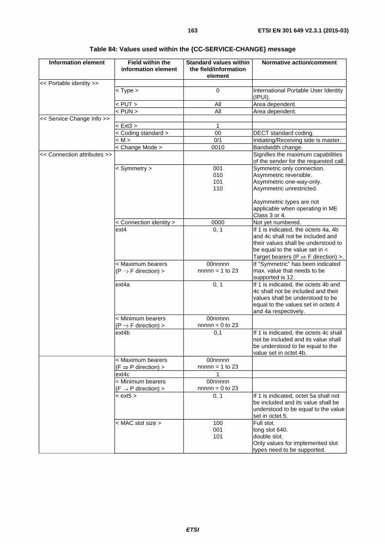
ETSI
ETSI EN 301 649 V2.3.1 (2015-03)163
Table 84: Values used within the {CC-SERVICE-CHANGE} message
Information element Field within the information element
Standard values within the field/information
element
Normative action/comment
<< Portable identity >> < Type > 0 International Portable User Identity
(IPUI). < PUT > All Area dependent. < PUN > All Area dependent. << Service Change Info >> < Ext3 > 1 < Coding standard > 00 DECT standard coding. < M > 0/1 Initiating/Receiving side is master. < Change Mode > 0010 Bandwidth change. << Connection attributes >> Signifies the maximum capabilities
of the sender for the requested call. < Symmetry > 001
010 101 110
Symmetric only connection. Asymmetric reversible. Asymmetric one-way-only. Asymmetric unrestricted. Asymmetric types are not applicable when operating in ME Class 3 or 4.
< Connection identity > 0000 Not yet numbered. ext4 0, 1 If 1 is indicated, the octets 4a, 4b
and 4c shall not be included and their values shall be understood to be equal to the value set in < Target bearers (P ⇒ F direction) >.
< Maximum bearers (P ⇒ F direction) >
00nnnnn nnnnn = 1 to 23
If "Symmetric" has been indicated max. value that needs to be supported is 12.
ext4a 0, 1 If 1 is indicated, the octets 4b and 4c shall not be included and their values shall be understood to be equal to the values set in octets 4 and 4a respectively.
< Minimum bearers (P ⇒ F direction) >
00nnnnn nnnnn = 0 to 23
ext4b 0,1 If 1 is indicated, the octets 4c shall not be included and its value shall be understood to be equal to the value set in octet 4b.
< Maximum bearers (F ⇒ P direction) >
00nnnnn nnnnn = 1 to 23
ext4c 1 < Minimum bearers
(F ⇒ P direction) > 00nnnnn
nnnnn = 0 to 23
< ext5 > 0, 1 If 1 is indicated, octet 5a shall not be included and its value shall be understood to be equal to the value set in octet 5.
< MAC slot size > 100 001 101
Full slot. long slot 640. double slot. Only values for implemented slot types need to be supported.

ETSI
ETSI EN 301 649 V2.3.1 (2015-03)164
Information element Field within the information element
Standard values within the field/information
element
Normative action/comment
< MAC service P ⇒ F >
0010, 0011, 0110, 0111
IPM; detect only. IPMR; Mod-2 correct. IPQ; detect only. IPQR; Mod-2 correct. Support of "IP; Mod-2 correct" is
optional. For the support of IPQ services
see clause 10.13. < ext5a > 1 < spare > 1000 < MAC service F ⇒ P > 0010,
0011, 0110, 0111
IPM; detect only. IPMR; Mod-2 correct. IPQ; detect only. IPQR; Mod-2 correct. Support of "IP; Mod-2 correct" is
optional. For the support of IPQ services see
clause 10.13. < Ext6 > 1, 0 If 1 is indicated, octet 6a shall not
be included and its value shall be understood to be equal to the value set in octet 6.
< CF channel attributes
P ⇒ F >
000, 010, 011, 100, 101
CF never (CS only). CF priorities A, B, C or D. Support of CF is optional.
< MAC packet life time P ⇒ F >
0 to 7
Values > 0 only for IP_error_correct (IPMR or IPQR).
< Ext6a > 1 < CF channel attributes
F ⇒ P >
000, 010, 011, 100, 101
CF never (CS only). CF priorities A, B, C or D. Support of CF is optional.
< MAC packet life time F ⇒ P >
0 to 7 Values > 0 only for IP_error_correct (IPMR or IPQR).
< Ext 7 > 1 See note 2. < A-attributes > 000 2-level modulation scheme. < B-attributes > 000,
001, 010
2-level modulation scheme. 4-level modulation scheme. 8-level modulation scheme. The support of 4 and 8 level modulation scheme is optional.
NOTE 1: The direction of the connection downlink (FT-to-PT) or up-link (PT-to-FT) will be dynamically negotiated at MAC layer.
NOTE 2: For backwards compatibility, if octet 7 is not included support of 2-level modulation scheme for both A- and B-field shall be assumed.
Table 85: Values used within the {CC-SERVICE-ACCEPT} message
Information element Field within the information element
Standard values within the field/information
element
Normative action/comment
See table 84 See table 84 See table 84 All optional - The receiving side is not allowed to suggest back different to the requested settings.

ETSI
ETSI EN 301 649 V2.3.1 (2015-03)165
12.6.1.1 Associated procedures
12.6.1.1.1 Timer F/P < CC_service > management
< CC_service >: Service Change timer.
Value: 20 seconds.
Start: {CC-SERVICE-CHANGE} message is sent.
Stop: An indication for link release from the DLC is received; A {CC-SERVICE-ACCEPT} or a {CC-SERVICE-REJECT} message is received; {CC-RELEASE}, {CC-RELEASE-COM} messages are sent or received.
12.6.1.2 Exceptional cases
12.6.1.2.1 Service change request is rejected
If the receiving side is not able to handle the requested service change it shall reject it.
Table 86: Values used within the {CC-SERVICE-REJECT} message
Information element Field within the information element
Standard values within the field/information
element
Normative action/comment
See table 84 See table 84 See table 84 All optional.
12.6.1.3 Examples
The modification of the lower resources is initiated from the higher layers where exchange of NWK layer messages is involved. The resources assignment is done at the lower layers. To provide proper functioning the LLME shall ensure that all responsible layers and processes are informed in time for the result from the NWK layer procedures before a resources allocation/modification is to be made at the lower layers.
Figure 23: Example of service change with the receiving side initiating the resources allocation
DL_SERVICE_MOD-req
(attributes)
(attributes)
CC-SERVICE-ACCEPT
CC-SERVICE-CHANGE(Service negotiation,receiving side is master)
MAC_MOD-cfm(result)
MAC_MOD-cfm(result)
MAC_MOD-req()
PT_nwk PT_dlc PT_mac FT_mac FT_dlc FT_nwk
Actions taken
DL_SERVICE_MOD-req
DL_SERVICE_MOD-cfm
DL_SERVICE_MOD-sfm
MAC_MOD-req

ETSI
ETSI EN 301 649 V2.3.1 (2015-03)166
12.6.2 Service change - slot type change
The procedure relates to feature In Call Service Change [DPRS-N.35] and is similar to the Bandwidth change procedure as described in clause 10.7.1 and in ETSI EN 300 175-5 [5], clauses 9.6.1 and 9.6.2. The following text together with the associated clauses defines the mandatory requirements with regard to the present document.
The slot type associated to the connection may be changed by invoking the Service Change Procedure with the Information Element <<Connection-ATTRIBUTES >> indicating the target slot type. Upon successfully completion of the NWK layer procedure, then the MAC layer procedure for changing slot type shall be performed as described in clause 10.7.2.2.
The allowed parameters in the Information Element <<Connection-ATTRIBUTES >> are indicated in table 84 of clause 12.6.1.
Only changes to values of parameters corresponding to implemented slot types need to be supported. Implementation should be able to reply with a {CC-SERVICE-REJECT} if a change to a not supported value is intended.
12.6.2.1 Associated procedures
See clause 12.6.1.1.
12.6.2.2 Exceptional cases
See clause 12.6.1.2.
12.6.2.3 Examples
See clause 12.6.1.3.
12.6.3 Service change - MAC service change
The procedure relates to feature In Call Service Change [DPRS-N.35] and is similar to the Bandwidth change procedure as described in clause 10.7.1 and in ETSI EN 300 175-5 [5], clauses 9.6.1 and 9.6.2. The following text together with the associated clauses defines the mandatory requirements with regard to the present document.
The MAC service associated to the connection may be changed by invoking the Service Change Procedure with the Information Element <<Connection-ATTRIBUTES >> indicating the target MAC service type. Upon successfully completion of the NWK layer procedure, then the MAC layer procedure for changing service type shall be performed as described in clause 10.7.2.1.
The allowed parameters in the Information Element <<Connection-ATTRIBUTES >> are indicated in table 84 of clause 12.6.1.
Only changes to values of parameters corresponding to implemented MAC services need to be supported. Implementation should be able to reply with a {CC-SERVICE-REJECT} if a change to a not supported value is intended.
12.6.3.1 Associated procedures
See clause 12.6.1.1.
12.6.3.2 Exceptional cases
See clause 12.6.1.2.
12.6.3.3 Examples
See clause 12.6.1.3.
12.6.4 Service change - modultation schema change
The procedure relates to feature In Call Service Change [DPRS-N.35] and is similar to the Bandwidth change procedure as described in clause 10.7.1 and in ETSI EN 300 175-5 [5], clauses 9.6.1 and 9.6.2. The following text together with the associated clauses defines the mandatory requirements with regard to the present document.

ETSI
ETSI EN 301 649 V2.3.1 (2015-03)167
In systems supporting High Level Modulation, the modulation level associated to the connection may be changed by invoking the Service Change Procedure with the Information Element <<CONNECTION-ATTRIBUTES >> indicating the target A and B field modulation levels.
The allowed parameters in the Information Element <<Connection-ATTRIBUTES >> are indicated in table 84 of clause 12.6.1.
Only changes to values of modulation level parameters corresponding to implemented modes need to be supported. Implementation should be able to reply with a {CC-SERVICE-REJECT} if a change to a not supported value is intended.
12.6.4.1 Associated procedures
See clause 12.6.1.1.
12.6.4.2 Exceptional cases
See clause 12.6.1.2.
12.6.4.3 Examples
See clause 12.6.1.3.
12.6.5 Service change - DPRS Management Class and other Call-attributes change
The procedure relates to feature In Call Service Change [DPRS-N.35] and is similar to the Bandwidth change procedure as described in clause 10.7.1 and in ETSI EN 300 175-5 [5], clauses 9.6.1 and 9.6.2. The following text together with the associated clauses defines the mandatory requirements with regard to the present document.
The DPRS management Entity Class associated to the connection may be changed by invoking the Service Change Procedure with the Information Element <<CALL-ATTRIBUTES >> indicating the target DPRS ME Class in the field <Network layer Attributes>.
The procedure may be also invoked to change any other parameter in IE <<CALL-ATTRIBUTES>> such as LU type and frame or C-plane channel.
The allowed parameters in the Information Element <<CALL-ATTRIBUTES >> are the same indicated in tables 78 and 79 of clause 12.5.
Only changes to values of parameters corresponding to implemented features/services need to be supported. Implementation should be able to reply with a {CC-SERVICE-REJECT} if a change to a not supported value is intended.
12.6.5.1 Associated procedures
See clause 12.6.1.1.
12.6.5.2 Exceptional cases
See clause 12.6.1.2.
12.6.5.3 Examples
See clause 12.6.1.3.
12.6.6 Service change - MAC Packet lifetime, DLC Window size, DLC Transit delay and CF channel attributes change
The procedure relates to feature In Call Service Change [DPRS-N.35] and is similar to the Bandwidth change procedure as described in clause 10.7.1 and in ETSI EN 300 175-5 [5], clauses 9.6.1 and 9.6.2. The following text together with the associated clauses defines the mandatory requirements with regard to the present document.

ETSI
ETSI EN 301 649 V2.3.1 (2015-03)168
The MAC Packet lifetime, DLC Window size, DLC Transit delay and CF channel attributes associated to the
connection may be changed by invoking the Service Change Procedure.
For changing the MAC Packet lifetime or the CF channel attributes, the Information Element
<< CONNECTION-ATTRIBUTES >> shall be used indicating the target parameters.
For changing the DLC Window size, the Information Element <<WINDOW-SIZE >> shall be used indicating the target value(s) of the Window size.
For changing the DLC Transit Delay, the Information Element <<TRANSIT-DELAY >> shall be used indicating the target values of the Transit Delay.
The allowed parameters in these Information Elements are the same indicated in tables 78 and 79 of clause 12.5.
Only changes to values of parameters corresponding to implemented features/services need to be supported. Implementation should be able to reply with a {CC-SERVICE-REJECT} if a change to a not supported value is intended.
MAC Packet lifetime change needs to be supported only if MAC IP_error_correct services are implemented.
12.6.6.1 Associated procedures
See clause 12.6.1.1.
12.6.6.2 Exceptional cases
See clause 12.6.1.2.
12.6.6.3 Examples
See clause 12.6.1.3.
12.7 Service change - IWU-attributes change
12.7.1 IWU-attributes change - General
The procedure relates to feature In Call Service Change [DPRS-N.35] and is similar to the Bandwidth change procedure as described in clause 10.7.1 and in ETSI EN 300 175-5 [5], clauses 9.6.1 and 9.6.2. The following text together with the associated clauses defines the mandatory requirements with regard to the present document.
The IWU- attributes change shall be defined as changes that may be realized by modification of the existing MAC connection. The << IWU-ATTRIBUTES >> element shall always be included to define the new settings.
For the {CC-SERVICE-CHANGE}, {CC-SERVICE-ACCEPT} and {CC-SERVICE-REJECT} the requirements from clause 12.6 apply with the following modification.
Table 87: Values used within the {CC-SERVICE-CHANGE} message
Information element Field within the information element
Standard values within the
field/information element
Normative action/comment
<< IWU attributes >> < Lenght of Contents > 4 to 23 Values > 7 only possible with IP IWU.
Values > 5 only possible if octets 5b/5c provided or IP IWU.
< Coding standard > 01 < Profile > 00001 Stream support. 00000 FREL support. < Negotiation Indicator > 000, 010 Shall be as set during the call
establishment. < Profile Subtype > 0000 Ethernet (WLAN). 1000 Interworking to V.24 circuits (RS232). 0001 IEEE 802.5 [14] (see clause B.5).

ETSI
ETSI EN 301 649 V2.3.1 (2015-03)169
Information element Field within the information element
Standard values within the
field/information element
Normative action/comment
0010 Internet Protocol (IP) (see clause B.6). 0100 Point-to-Point Protocol (see clause B.7). 1000 DPRS Generic Media Encapsulation
Protocol (see clause B.8). <Maximum SDU size>
(octets 5 and 5a) ≥ 191 (equivalent to
1 528 octets) At least 1 528 octets (codec as 191) shall be supported (see note).
<Maximum SDU size> (octets 5b and 5c)
≥ 191 (equivalent to 1 528 octets)
Optional octet. Used only if FP ⇒ PP and PP ⇒ FP values are different.
< Profile Subtype attributes>
All The required for support value and the complete structure of the IWU attributes in regard to the present document are defined in the relevant Interworking annexes of the present document. If IP IWU, an IPv4 or IPv6 address may be optionally transported. See clauses B.8 and B.2 for Generic Media Encapsulation.
<< Service Change Info >> < Ext3 > 1 < Change Mode > 1100 IWU attribute change. NOTE: Value 191 (equivalent to 1 528 octets) is coded as "0000001"B in octet 5 and "0111111"B in octet 5a.
12.7.1.1 Associated procedures
See clause 12.6.1.1.
12.7.1.2 Exceptional cases
See clause 12.6.1.2.
12.7.1.3 Examples
See clause 12.6.1.3.
12.7.2 Interworking type change
The IWU-attributes change may be used to change the Interworking type and the protocol transported over DPRS. Procedure is executed using the Service Change procedure and indicating the target interworking type in the profile subtype field. The profile subtype attributes (octet 6) may also be provided in the message.
12.7.3 IP address change (IP IWU)
This clause applies only to Interworking type Internet Protocol (clause B.6).
The change of the IP address is a particular case of IWU attributes change. If IWU is Internet Protocol (IP, clause B.6), an IPv4 or IPv6 address may be transported over the Profile subtype octets. An IP address sent by the FT to the PT has the meaning of dynamic IP address allocated to such PP by the FP. Therefore, the Service Change procedure may be used to allocate or re-allocate such IP address.
Only the transport of the addresses for the supported versions of IP (IPv4 and/or IPv6) needs to be implemented.
12.7.4 Maximum SDU size change
The IWU-attributes change may be used to change the Maximum SDU size. Procedure is executed using the Service Change procedure and indicating the target maximum SDU size(s) in octets 5-5c.

ETSI
ETSI EN 301 649 V2.3.1 (2015-03)170
12.8 Dynamic Parameters Allocation
12.8.1 General requirements
The procedure is related to feature DPRS-N.33, Dynamic parameters allocation. The following text together with the associated clauses defines the mandatory requirements with regard to the present document.
For proper functioning of the DPRS protocol it is necessary that a number of dynamic parameters be allocated beforehand. For this purpose two types of mechanisms are provided: the Sent-IE and Default-IE mechanisms.
Other relevant clauses. The exchanged parameters are used at various levels in the device. The following clauses are therefore also relevant for the description of the device behaviour and requirements relating to the reception and sending of these parameters:
- clause 9 (Management Entity requirements),
- clause 10 (MAC layer procedures),
- clause 11 (DLC layer procedures).
12.8.2 Sent IE and Default IE Dynamic Parameter Allocation
12.8.2.1 Sent-IE mechanism
The dynamic parameters are allocated through an exchange of information included in << SETUP-CAPABILITY >> information element.
If the device (PT or FT) supports several DPRS management classes, the sent IE shall be sent for all supported classes. In other words:
• a setting that is described in the present document as orthogonal to class definitions shall apply for all supported classes;
• a setting that is described in the present document as specific to a given class:
- shall be sent if the class is supported,
- is sometimes sent even though the class is not supported, because of the IE structure (in that case, its value shall be ignored),
- shall be ignored by all other classes.
12.8.2.2 Default-IE mechanisms
A device is allowed to omit the <<SETUP CAPABILITY>> IE if it wants to indicate only default values.
NOTE 1: This is not to be confused with the default mechanisms at settings level (see clause 12.8.4), that applies when the <<SETUP CAPABILITY>> IE is used.
NOTE 2: Absence of the <<SETUP CAPABILITY>> IE does not mean that Dynamic Parameter Allocation is not used: it is used, but with the default mechanism described here which is part of the feature.
Several default IEs are provided within the DPRS-N.33 feature allowing to still use dynamic parameter allocation if at least one of the parties (or both) does not send any <<SETUP CAPABILITY>> IE.
NOTE 3: This is not to be confused with the default values at settings level (see clause 12.8.4), that apply to a sent IE (resp. default IE) when a parameter is absent from the sent IE (resp. from the description of the used default IE).

ETSI
ETSI EN 301 649 V2.3.1 (2015-03)171
Table 87a: Default IEs defined in the present document
Supported class Reference Comment Class 2 Clause 12.8.10 Clause 12.8.6 also describes the
set of allowed values for a sent IE. Class 3 Annex 2.1, table A.17 (see note ) • Only to be considered if a
basic service is used at connection time.
• See also 12.8.7 for the set of allowed values
Class 4 Annex 2.2, table A.11
NOTE: The default IE as described in table A.17 may be different on PT and FT side for some settings, in order to reflect the implied negotiation.
12.8.2.3 Support of these mechanisms
A device may support several DPRS management classes.
It shall at least implement all existing default IE mechanisms for all the classes that it supports.
It may additionally support the sent IE based mechanism for some or all of the supported classes, especially if it needs to modify a parameter in a default IE.
12.8.2.4 Simultaneous use of both mechanisms (one from each side)
When only one of the sides (PT or FT) sends an IE for the class used for the connection, the following table shall apply.
Table 87b: Rules for combination of sent IE with default IE
Class used for the
connection (note 1)
Use of basic service by
initiating side?
Mandatory behaviour Comment
Class 2 N/A
Combination of both. The sent IE from one side shall be used in combination with the default IE (as if it was sent) from the other side for the determination of the actual setting values used for the connection (note 2)
This implies that a PT or FT supporting Class 2 shall at least support the reception of a sent IE for Class 2 even if it does not itself send any IE for Class 2 and relies on the default IE
Class 3 or
Class 4
YES
Default IE used from both sides. - the sent IE (whether sent by the initiating side or the other side) shall be ignored by both sides - the default IE shall be used as if sent from both sides
This implies that a device (PT or FT) sending an IE, also supports the default IE for the case the other side does not send any IE
NO (note 3) Should not occur. - no default value is currently defined in the present document
This should not occur (i.e. in that case both sides should send an IE) (note 4)
NOTE 1: When the management class can only be determined at connection setup (i.e. if both sides support several common classes) the applicable behaviour may be only determined at connection time. The actual management class of a connection is determined either through the <<BASIC SERVICE>> IE (if used), or through the <<CALL ATTRIBUTES>> IE of the {CC-SETUP} from the initiating side.
NOTE 2: If one side does not receive any <<SETUP CAPABILITY>> IE, it shall react as if the IE had been received with all fields set to the default IE defined values.
NOTE 3: In other words, the used basic service subfield value is 'other'. NOTE 4: In particular, a device supporting GMEP cannot use the default IE mechanism except if a basic service is used,
because related capabilities described in clause 12.8.5 are not part of any existing default IE descriptions.
Mechanism used for an actual connection. The mechanism used (sent or default IE) for an actual connection may be determined using table A.5 of clause A.1.5.

ETSI
ETSI EN 301 649 V2.3.1 (2015-03)172
12.8.3 Transport of the <<SETUP CAPABILITY>> IE (when used)
Sending side requirements. When a device uses the sent IE mechanism it shall send the <<SETUP CAPABILITY>> IE as follows:
If sent by the device, the << SETUP-CAPABILITY >> IE shall be included:
- during the subscription registration, by the PT in the {ACCESS-RIGHTS-REQUEST} message and by the FT in the {ACCESS-RIGHTS-ACCEPT} message. For the relevant procedure requirements and complete contents of these messages, the requirements of ETSI EN 300 444 [11], clause 8.30 shall apply;
- during the location registration, by the PT in the {LOCATE-REQUEST} message and by the FT in the {LOCATE-ACCEPT} message. For the relevant procedure requirements and complete contents of these messages, the requirements of ETSI EN 300 444 [11], clause 8.28 shall apply.
In addition, the FT may include the << SETUP-CAPABILITY >> IE in a {MM-INFO-SUGGEST} message (see clause 12.8.6) or in a {CLMS-FIXED} message (see clause 12.8.8).
Receiving side requirements. Both sides are required to understand and react properly upon receipt of a << SETUP-CAPABILITY >> information element as described in this clause.
12.8.4 Service and parameter settings support indication (PT or FT)
NOTE 1: This clause applies independently of the DPRS management class (or classes) that the device supports.
NOTE 2: <Application Protocol or supported capability Indicator> is described separately in clause 12.8.5.
Use of a setting for an actual connection.
A given service or parameter setting value shall be used for an actual connection after indication by both sides (resp. FP only) of their chosen service and parameter settings value, using the <<SETUP CAPABILITY>> IE (sent of default), and by respecting the relevant negotiation method.
EXAMPLE 1: For class 2, a service setting value belonging to the allowed set of values described in clause 12.8.6 (table 88) shall be used for an actual connection: - either if both sides indicate that value in the (sent of default) <<SETUP CAPABILITY>> IE, - or after using table 88 itself for setting negotiation (see notes 5, 6 in table 88) - or by using a (future) profile based on the 'Dynamic Parameter Allocation' feature that specifies how the setting is negotiated (see note 4 in table 88).
EXAMPLE 2: For class 2, a parameter setting values belonging to the allowed set of values described in clause 12.8.6 (table 88) shall be used for an actual connection by using the negotiation rules described in clauses A.1.3.1 and A.1.3.2.
EXAMPLE 3: For class 3, the parameter setting T910_Class_3 shall be chosen by the FP within the allowed set of values as described in clause 12.8.7 (table 88b).

ETSI
ETSI EN 301 649 V2.3.1 (2015-03)173
Bit: 8 7 6 5 4 3 2 1 Octet: 0 << SETUP-CAPABILITY >> 1 Length of Contents (L) 2 1 0 0 1 Setup Page 3 0/1 Service settings_1 (for all classes; see note 1) 4 0/1 ... ... 1 Service settings_n 4n-1 0/1 Parameters settings_1 (for class 2) 5 0/1 Parameters settings_2 (for class 3; see note 2) 5a 0/1 … … 1 Parameter settings_n 5n-1 T903 6 T904 6a T905 6b T909 6c T910 6d T911 6e See text Max nr of bearers upstream 6f See text Max nr of bearers downstream 6g T910_Class_3 6h … … 0/1 Application Protocol or supported capability Indicator 1 7 0/1 ... (see note 3) ... 1 Application Protocol or supported capability Indicator n 7n-1
NOTE 1: However, bit 2 and bit 3 of octet 4 are class 2 specific. NOTE 2: If class 3 is not supported (i.e. if either class 4 only, or classes 2 and 4 only are supported), octet 5a shall
not be transmitted. Currently only bit 1 is defined in octet 5a. If class 3 is supported on PT side, octet 5a shall be transmitted even though all bits shall be set to 0 (see T910_Class 3 parameter below).
NOTE 3: Except when otherwise stated, 'Application Protocol or supported capability Indicators' are valid for all classes.
Figure 24: <<SETUP-CAPABILITY>> information element for DPRS
Service settings (octet group 4): This is a bit mapped octet group. A "1" indicates support for the specified service setting. Reserved bits shall be set to zero and need not be checked in the receiver.
Service_settings_1 Coding (Octet 4):
MAC settings (bits 1, 2, 3 of octet 4)
Bits 3 2 1 Meaning x x 1 IP_error_correct (IPMR or IPQR) supported.
0 1 x (class 2 specific) Allow suppression of bearer quality messages for asymmetric connection (ETSI EN 300 175-3 [3], clause 7.3.5.4) only if all Q2 bits are = 1.
1 0 x (class 2 specific) Allow suppression of bearer quality messages for asymmetric connection (ETSI EN 300 175-3 [3], clause 7.3.5.4) in any case.
All other values reserved.
Support of simultaneous DPRS and voice calls (bits 4, 5 of octet 4)
Bits 5 4 Meaning 1 1 Support of simultaneous DPRS and voice active calls (see note 3). 1 0 Support of simultaneous DPRS logical (but not active) calls plus an active voice call (see
notes 4 and 5). 0 1 Simultaneous DPRS and voice calls not supported, however switching procedure supported
(see note 6). 0 0 No information provided or no simultaneous support at all.

ETSI
ETSI EN 301 649 V2.3.1 (2015-03)174
Support of multiple DPRS connections (bits 6, 7 of octet 4)
Bits 7 6 Meaning 1 1 Support of multiple simultaneous DPRS logical and active physical connections (see notes 7, 8
and 9). 1 0 Support of multiple simultaneous DPRS logical connections (but not active, see notes 8, 9 and
10). 0 1 Reserved. 0 0 Multiple DPRS connections not supported.
NOTE 3: This flag indicates that the sending peer is able to support simultaneously a voice service call plus one or several (depending on bits 6 and 7) DPRS active connections, all of them with bearers over the air interface.
NOTE 4: This flag indicates that the sending peer does not support simultaneously a voice call plus one or several DPRS active connections. However it supports a voice service call in active state combined with one or more DPRS connections (as indicated by bits 6 and 7) in suspend state.
NOTE 5: In this case, the active voice call is considered as valid handshake for the DPRS connection(s). So there is no need for DPRS handshake procedure when the voice call is active.
NOTE 6: In this case, the DPRS call has to be released in order to complete the setup of the voice call and vice versa. The flag indicates that the peer is able to execute the switching procedure.
NOTE 7: This flag indicates that the sending peer is able to support multiple simultaneous active DPRS connections with bearers over the air interface.
NOTE 8: This flag indicates that the sending peer is able to support multiple simultaneous logical DPRS connections, but not active at the same time.
NOTE 9: Both, virtual calls and PVCs are considered DPRS connections.
NOTE 10: This is in addition to the possible support of a simultaneous voice call as indicated by bits 4 and 5.
Service_settings_n Coding (Octet 4n-1): This is provided in case of demands for further DPRS standardization.
Parameters_settings_1 (octet group 5): This is a bit mapped octet group.
A value of "1" indicates that a value for the considered parameter is provided in octect group 6.
A value of "0" indicates that no value is provided in octet group 6 for the considered parameter, for one of the following reasons:
- the device (PT or FT) shall not provide a value for this parameter.
EXAMPLE 4: Parameters T903, T904, T905, T910 are always set by the FP (see clause A.1.3.1), so the PP shall not provide any value for them (and no default value is defined on PP side for them).
- the device (PT or FT) shall provide a value for this parameter, but the default value defined in the present document for this parameter shall be assumed.
EXAMPLE 5: Clause A.1.3.1 indicates possible default values (on FP side only) for values set by the FP. Clause A.1.3.2 indicates possible default values on PP and/or FP side (depending on the case), for negotiable parameters.
- or (bit 7 only), the device may provide a value for this parameter, but decides not to do so (no default value is defined in the present document in this case).
NOTE 11: The default values for all parameters are provided in annex A.
Reserved bits shall be set to zero and need not be checked in the receiver.

ETSI
ETSI EN 301 649 V2.3.1 (2015-03)175
Parameters_settings_1 (octet 5):
Bits 7 6 5 4 3 2 1 Meaning x x x x x x 1 Timer T903 value is provided (in octect 6). x x x x x 1 x Timer T904 value is provided (in octect 6a). x x x x 1 x x Timer T905 value is provided (in octect 6b). x x x 1 x x x Timer T909 value is provided (in octect 6c). x x 1 x x x x Timer T910 value is provided (in octect 6d).
x 1 x x x x x Timer T911 value is provided (in octet 6e). 1 x x x x x x Supported connection types and maximum bearers numbers is provided (in octet 6f and 6g).
Parameters_settings_2 (octet 5a):
Bits 7 6 5 4 3 2 1 Meaning x x x x x x 1 Timer T910_Class_3 value is provided (in octect 6h).
Parameter_settings 3 and beyond are reserved for further expansion of the set of parameters. Meanwhile, the bit 8 of octet 5a (Parameter_settings_2) shall be set to 1.
When number of values are provided they shall be provided in the order indicated here.
EXAMPLE 6: If only T905 and T910 values are included, octets 5, 6b and 6d need to be included in this order.
Parameters (Octet group 6):
Timer T903 value (octet 6): The value shall be binary coded with 1 unit = 2 frames; the value "11111111" is reserved and shall not be used.
Timer T904 value (octet 6a): The value shall be binary coded with 1 unit = 1 frame; the value "11111111" is reserved and shall not be used.
Timer T905 value (octet 6b): The value shall be binary coded with 1 unit = 1 frame; the value "11111111" is reserved and shall not be used.
Timer T909 value (octet 6c): The value shall be binary coded with 1 unit = 1 multi frame; the value "11111111" shall be understood as "infinite";
If the < Setup capability coding > value indicates "01" this value (if included) shall be set to "0".
Timer T910 value (octet 6d): The value shall be binary coded with 1 unit = 4 multi frames; the value "11111111" shall be understood as "infinite".
Timer T911 value (octet 6e): The value shall be binary coded with 1 unit = 4 multi frames; the value "11111111" shall be understood as "infinite".
Bearers support (octets 6f and 6g):
It indicates which types of connection (within the types described in < Connection Attributes >, see ETSI EN 300 175-5 [5], clause 7.7.11), and the maximum number of bearers that are supported for the FT or PT sending the parameter.
These octets have the following structure:
Bearers support 1st octet (octet 6f): Bits 8 7 6 Meaning x x 1 Symmetric only connections supported (see ETSI EN 300 175-5 [5], clause 7.7.11). All other values Reserved Reserved bits 7 and 8 shall be set to "0".
Bits 5 4 3 2 1 Meaning NNNNN Maximum supported number of bearers upstream (see note 4).
NOTE 12: The maximum supported number of bearers parameters refers to the maximum value that can be set by a call under current conditions. When broadcasted by the FP, the value can be dynamically changed according to the situation.

ETSI
ETSI EN 301 649 V2.3.1 (2015-03)176
Bearers support 2nd octet (octet 6g): Bits 8 7 6 Meaning x x 1 Asymmetric reversible connections supported (see ETSI EN 300 175-5 [5], clause 7.7.11). x 1 x Asymmetric one-way-only connections supported (see ETSI EN 300 175-5 [5], clause 7.7.11). 1 x x Asymmetric unrestricted connections supported (see ETSI EN 300 175-5 [5], clause 7.7.11).
Bits 5 4 3 2 1 Meaning NNNNN Maximum supported number of bearers downstream (see note 4).
Timer T910_Class_3 value (octet 6h): The value shall be binary coded with 1 unit = 4 multi frames; the value "11111111" shall be understood as "infinite".
More Parameters may be added in future standardization by including of octet 6i and following 6j, ... 6n.
12.8.5 Application media protocol support indication (PT and FT)
The present clause applies to a device supporting DECT generic media encapsulation transport as described in clause B.8. It therefore applies to:
- All FTs that indicate support of the DECT generic media encapsulation transport in the Extended fixed part capabilities as indicated in clause 12.16.
- All PTs that indicate support of the DECT generic media encapsulation transport in the << Terminal capability >> IE as indicated in clause 12.3.
Support of application protocols and additional capabilities. The device shall provide additional information as to which application protocols are supported and may use the DECT generic media encapsulation transport, and other optional capabilities.
This shall be done by using one or more 'Application Protocol or supported capability Indicator' octet(s) in octet group 7 of the <<SETUP-CAPABILITY>> IE, which shall be provided to the other side during subscription and location registration procedures as described in clause 12.8.3.
Additional support during device lifecycle. If a new Application protocol is added after the subscription is completed, the devices shall:
- perform subscription registration again in order to indicate support of the new protocol;
- indicate support of this protocol during each subsequent location registration.
Reception of support information. Both sides are required to understand and react properly upon receipt of a << SETUP-CAPABILITY >> information element as described in this clause.
Indication of actual protocol used (<< IWU-ATTRIBUTES >> IE or basic service). In addition to the provisions given in the present clause regarding setup capability, both DECT devices involved in a DPRS virtual call carrying Generic Media Encapsulation Protocol shall indicate the real protocol or protocols transported over each context of the call during the context creation at call setup or at Service Change using the << IWU-ATTRIBUTES >> information element as specified in clause B.2.1.1.4.
In regard to the Application media profile support indicated in the < Application protocol or supported capability indicator > octets, both sides are allowed to use a particular protocol only if both sides have indicated support of it.
Generic Media Encapsulation supported protocols and capabilities (octet group 7):
The Generic Media Encapsulation supported protocols and capabilities octet group may be used to indicate the support of one or several protocols and the support of some optional capabilities.
Several octets may be used if needed.
NOTE: The basic structure of the <<SETUP-CAPABILITY>> information element relevant to DPRS is provided in clause 12.8. The present clause only provides the codings relevant to the DPRS Generic media encapsulation transport, that is, the Application Protocol or supported capability Indicator coding.

ETSI
ETSI EN 301 649 V2.3.1 (2015-03)177
Application Protocol or supported capability Indicator (octet group 7): Bit 7 6 5 4 3 2 1 Meaning 0 0 0 0 0 0 0 Reserved. 0 0 0 0 0 0 1 HTTP supported, limited set nr.1 (as specified in clause B.8.3.3). 0 0 0 0 0 1 0 HTTP supported, limited set nr.2 (as specified in clause B.8.3.4). 0 0 0 0 0 1 1 HTTP supported, limited set nr.3 (as specified in clause B.8.3.5). 0 0 0 0 1 0 0 Full HTTP supported (as RFC 2616 [27]). 0 0 0 0 1 0 1 SMTP supported, limited set nr.1 (as specified in clause B.8.3.6). 0 0 0 0 1 1 0 SMTP supported (as RFC 5321 [29]). 0 0 0 0 1 1 1 POP3 supported (as RFC 1939 [23]). 0 0 0 1 0 0 0 RTP supported (as RFC 3550 [32]). 0 0 0 1 0 0 1 SIP supported (as RFC 3261 [31]). 0 0 0 1 0 1 0 DNS supported (as RFC 1034 [35] and RFC 1035 [36]). 0 0 0 1 1 1 0 Application protocols over TCP [22] (in general) and sequence numbers supported. 0 0 0 1 1 1 1 Application protocols over UDP [21] (in general) supported. 0 1 0 0 0 0 1 Application packet size of up to 1,5 kBytes supported in PT ⇒ FT direction. 0 1 0 0 0 1 0 Application packet size of up to 6 kBytes supported in PT ⇒ FT direction. 0 1 0 0 0 1 1 Application packet size of up to 12 kBytes supported in PT ⇒ FT direction. 0 1 0 0 1 0 0 Application packet size of up to 24 kBytes supported in PT ⇒ FT direction. 0 1 0 0 1 0 1 Application packet size of up to 48 kBytes supported in PT ⇒ FT direction. 0 1 0 0 1 1 0 Application packet size of up to 100 kBytes supported in PT ⇒ FT direction. 0 1 0 0 1 1 1 Application packet size of up to 200 kBytes supported in PT ⇒ FT direction. 0 1 0 1 0 0 0 Application packet size of up to 400 kBytes supported in PT ⇒ FT direction. 0 1 0 1 0 0 1 Application packet size of up to 800 kBytes supported in PT ⇒ FT direction. 0 1 0 1 1 1 1 Application packet size unrestricted in PT ⇒ FT direction. 0 1 1 0 0 0 1 Application packet size of up to 1,5 kBytes supported in FT ⇒ PT direction. 0 1 1 0 0 1 0 Application packet size of up to 6 kBytes supported in FT ⇒ PT direction. 0 1 1 0 0 1 1 Application packet size of up to 12 kBytes supported in FT ⇒ PT direction. 0 1 1 0 1 0 0 Application packet size of up to 24 kBytes supported in FT ⇒ PT direction. 0 1 1 0 1 0 1 Application packet size of up to 48 kBytes supported in FT ⇒ PT direction. 0 1 1 0 1 1 0 Application packet size of up to 100 kBytes supported in FT ⇒ PT direction. 0 1 1 0 1 1 1 Application packet size of up to 200 kBytes supported in FT ⇒ PT direction. 0 1 1 1 0 0 0 Application packet size of up to 400 kBytes supported in FT ⇒ PT direction. 0 1 1 1 0 0 1 Application packet size of up to 800 kBytes supported in FT ⇒ PT direction. 0 1 1 1 1 1 1 Application packet size unrestricted in FT ⇒ PT direction. 1 0 0 0 0 0 1 Chopping option supported (clause B.8.2.2). 1 0 0 0 1 0 1 Support of "Generic Multiprotocol Interworking to External IP Networks" procedure
(clause B.8.4.1). 1 0 0 0 1 1 0 Support of "Multicontext Interworking to an application proxy" procedure (clause B.8.4.2). 1 0 0 1 0 1 0 Support of "Simplified single-context Interworking to External Networks (or to an application
proxy)" procedure (clause B.8.4.3).
All other values reserved
Application packet size. The codes indicating Application packet size shall be understood as the maximum application packet size that the peer that is sending the IE << SETUP CAPABILITY >> is able to transmit or receive (depending on the direction of the code). These values are assumed to be valid for all supported application protocols.
Two codes at most shall be used for the Application packet size capabilities (one for each direction). If the capabilities in both directions are the same, only one packet size indicator shall be used, and it shall be the one coded as "010xxxx"B. If the capabilities are different, then two codes shall be used.
The codes set by the FT and PT sides may be different. A peer should not send application packets larger than the max value that the other peer has indicated it may support.
Chopping option. If the code for chopping option is not present, it shall be understood as that the sending peer does not support the chopping option. Only if both peers support chopping, this option may be invoked in a call. The use of chopping, when supported, is negotiated context by context at context creation.

ETSI
ETSI EN 301 649 V2.3.1 (2015-03)178
12.8.6 Allowed and mandatory values for DPRS Class 2 PT and FT devices
For the DPRS Class 2 devices (PT or FT), the << SETUP-CAPABILITY >> information element as defined in ETSI EN 300 175-5 [5], clause 7.7.40 shall apply with the following additions/modifications. The following table describes the set of allowable values for each setting.
Table 88: Values used within the << SETUP-CAPABILITY >> information element
Information element Field within the information element
Standard values within the field/information
element
Normative action/comment
<< Setup capability >> < ext3 > 1 < Protocol discriminator > 001 DPRS. < Setup > i.e. "fast setup capability" 01 Mandatory to support (notes 5 and 6)
Fast setup is not supported. That is, only indirect setup ( i.e. Normal setup) is supported
10 Fast setup supported. < Page > i.e. "Page capability"
Flags are understood as supported when no virtual call is in progress.
01 Mandatory to support (note 5) Normal paging only supported (i.e. "normal duty cycle paging" only is supported).
10 Fast paging supported. 00 Low cycle paging supported. < ext4 > 1 < Service_settings_1 > 0000000 Summary of mandatory to support
values (see below). < MAC_settings_1 > bits 1, 2 and 3 xxxxxx0 Mandatory to support (notes 5 and 6)
IP_error_correct (IPMR or IPQR) NOT
supported. xxxxxx1 (optional) IP_error_correct (IPMR or
IPQR) supported.
xxxx00x Mandatory to support (note 5) Do not allow suppression of bearer quality messages for asymmetric connection
xxxx01x (optional) Allow suppression of bearer quality messages for asymmetric connection (ETSI EN 300 175-3 [3], clause 7.3.4.4) only if all Q2 bits are = 1.
xxxx10x (optional) Allow suppression of bearer quality messages for asymmetric connection (ETSI EN 300 175-3 [3], clause 7.3.4.4) in any case.
< Support of simultaneous DPRS and voice calls >
See note 4
xx00xxx Mandatory to support (note 5) No information provided or no simultaneous support at all.
xx01xxx (optional) No simultaneous voice and DPRS call supported, but switching procedure supported.
xx10xxx (optional) Support of simultaneous voice and DPRS call, but not active.
xx11xxx (optional) Support of simultaneous voice and DPRS active call.

ETSI
ETSI EN 301 649 V2.3.1 (2015-03)179
Information element Field within the information element
Standard values within the field/information
element
Normative action/comment
< Support of multiple DPRS connections >
See note 4
00xxxxx Mandatory to support (note 5) Multiple DPRS connections not supported.
11xxxxx (optional) Support of multiple simultaneous DPRS logical and active physical connections.
10xxxxx (optional) Support of multiple simultaneous DPRS logical connections (but not active).
< Parameter_settings_1 > As relevant PT:xx0x000 FT:xxxxxxx
If a bitmap position is set to 0, no value for the corresponding parameter is provided (see notes 1 and 2)
T903 (FP only; see note 3) For the allowed values see clause A.1.3.1
A value for this parameter is included if indicated in < Parameter_settings_1 > (xxxxxx1). Otherwise, default value is assumed.
T904 (FP only; see note 3) For the allowed values see clause A.1.3.1
A value for this parameter is included if indicated in < Parameter_settings_1 > (xxxxx1x). Otherwise, default value is assumed.
T905 (FP only; see note 3) For the allowed values see clause A.1.3.1
A value for this parameter is included if indicated in < Parameter_settings_1 > (xxxx1xx). Otherwise, default value is assumed.
T909 For the allowed values see clause A.1.3.2
A value for this parameter is included if indicated in < Parameter_settings_1 > (xxx1xxx). Otherwise, default value is assumed.
T910 (FP only; see note 3) For the allowed values see clause A.1.3.1
A value for this parameter is included if indicated in < Parameter_settings_1 > (xx1xxxx). Otherwise, default value is assumed.
T911 For the allowed values see clause A.1.3.2
A value for this parameter is included if indicated in < Parameter_settings_1 > (x1xxxxx). Otherwise, default value is assumed.
Bearers support (2 octets ) Types of connection (bits 6,7,8) : All
Maximum number of bearers (bits 1 to 5):
1 to 23
A value for this parameter is included if indicated in < Parameter_settings_1 > (1xxxxxx). Otherwise, it means that no information on supported connection type and number of bearers is provided.
< Parameter_settings_2 > 0000001 Only transmitted if Class 3 is also supported
T910_Class_3 N/A Irrelevant for Class 2 Application Protocol
Indicator For the allowed values
see clause 12.8.5 Only if Generic media encapsulation Interworking is supported. Several octets may be used if multiple application protocols are supported.

ETSI
ETSI EN 301 649 V2.3.1 (2015-03)180
Information element Field within the information element
Standard values within the field/information
element
Normative action/comment
NOTE 1: A value of "0" for the bitmap position indicates either that the device shall not provide any value for this parameter (see note 3 below), or that the device shall provide a value for the parameter, but the default value as defined by the present document is assumed (see note 2 below).
NOTE 2: See clause A.1.3.1 for possible default values on FP side only. See clause A.1.3.2 for possible default values on PP and/or FP side, depending on the case.
NOTE 3: The PP shall not provide any value for this parameter, which is imposed by the FP (see clause A.1.3.1). Corresponding bitmap position is therefore set to 0 on PP side.
NOTE 4: If the profile using class 2 allows several values among the allowed values, it shall also indicate how the value used in the connection is negotiated.
NOTE 5: This is the value used in the default IE for class 2 defined in clause 12.8.10. It shall therefore be supported in addition to the indicated value in order to ensure interoperability with an implementation using the default class 2 IE.
NOTE 6: This value shall be the negotiated value if both parties (PT and FT) do not indicate the same value for the field.
12.8.7 Allowed values for DPRS Class 3 and 4 devices (PT or FT)
The values indicated in table 88a shall be used for configuration capabilities when operating in Class 3 or Class 4 management mode. This table contains values related to dynamic parameters allocation for Class 2, but not for Class 3 or 4 (because they are fixed or irrelevant for these classes).
NOTE 1: There is no default <<SETUP CAPABILITY>> IE when Class 3 or 4 is used, except if a basic service is used by the initiating side. Support of Class 4 (resp. of Class 3 and 4) should imply support of "LDS with Class 3 DPRS management" basic service defined in clause A.2.1 (resp. support of both basic services defined in clauses A.2.1 and A.2.2).
The allowed values indicated in table 88b are relevant when dynamic parameters allocation is used with a sent IE for Class 3 or 4, or when a default IE is defined in an application profile using Class 3 or 4.
NOTE 2: There is currently no default <<SETUP CAPABILITY>> IE defined when Class 3 or 4 is used, except if a basic service is also used by the initiating side. Support of Class 4 (resp. of Class 3 and 4) should therefore imply support of "LDS with Class 3 DPRS management" basic service defined in clause A.2.1 (resp. support of both basic services defined in clauses A.2.1 and A.2.2).

ETSI
ETSI EN 301 649 V2.3.1 (2015-03)181
Table 88a: Configuration values for Class 3 and Class 4 devices
Parameter Value Normative action/comment
Suspend timer Irrelevant. Free to the implementation Called T903 for Class 2 Wait timer. Fixed part Irrelevant. Free to the implementation Called T904 for Class 2 Wait timer. Random part Irrelevant. Free to the implementation Called T905 for Class 2 Fast setup detection timer Irrelevant. No fast setup supported Called T909 for Class 2 Handshake procedure timer Irrelevant for Class 4.
Applicable to Class 3 peers that support suspend initiation See Class 3_T910 in table 88b
Called T910 for Class 2
High duty cycle paging detection timer
Irrelevant. No high duty cycle required Called T911 for Class 2
Bearer support Symmetric only connections supported
See note
Bearers number upstream 1 See note Bearers number downstream 1 See note NOTE: These configuration elements are fix for Class 3 and 4 (but negotiated for Class 2 in the <<SETUP-
CAPABILITY>> IE).
Table 88b: Configuration values used in the <<SETUP-CAPABILITY>> IE, for Class 3 and Class 4 devices
Parameter Value Normative action/comment Service settings < Setup capability> 01 Fast setup is not supported < Page capability> 01 Indicates normal duty cycle
paging only Fast paging is not supported
Parameter settings Class 3_T910 Handshake procedure timer
For class 4: irrelevant For class 3: (5 to 254) × 4 DECT Multiframes + infinite coded as 255,
FP only timer, see note 2 Basic service "LDS with Class 3 DPRS management" uses value 94 = 376 MF = 60,16 s. See clause A.2.2.
<Application protocol or supported capability indicators>
See note 1
HTTP support HTTP supported, with either limited set nr. 1, 2 or 3 or Full HTTP at least supported. (see clause 12.8.5)
Basic services (defined in clause A.2) use value "HTTP limited set nr.2" (as specified in clause B.8.3.4)
Application packet size up to 1,5 kBytes supported in PT ⇒ FT direction up to 12 kBytes supported in FT ⇒ PT direction
see clause 12.8.5 When chopping is not used, application packet size is further limited through "Max SDU size" values negotiated at connection setup.
Interworking to external networks
Support of either B.8.4.1, B.8.4.2 or B.8.4.3 at least
see clause 12.8.5 Basic services (defined in clause A.2) use value "B.8.4.3, Simplified single-context Interworking to External Networks (or to an application proxy)"
NOTE 1: In order to indicate support of application protocols and capabilities, a sent IE may be used. A basic service as defined in clause A.2 may also be used (with no sent IE).
NOTE 2: The PP shall not provide any value for this parameter, which is imposed by the FP. Corresponding bitmap position is therefore set to 0 on PP side.

ETSI
ETSI EN 301 649 V2.3.1 (2015-03)182
12.8.8 Transport with {MM-INFO-SUGGEST} message (FT to PT)
For the transmission of the {MM-INFO-SUGGEST} message the Procedure for parameter retrieval initiated by the FT as specified in ETSI EN 300 175-5 [5], clause 13.7 shall apply.
For the contents of {MM-INFO-SUGGEST} the following requirements apply.
Table 89: Values used within the {MM-INFO-SUGGEST} message
Information element Field within the information element
Standard values within the field/information
element
Normative action/comment
<< Info type >> < Parameter type > 0000110 Dynamic parameters allocation. << Setup capability >> For the allowed values see table 88.
12.8.9 Transport with {CLMS-FIXED} message (FT to PT)
For the transmission of the {CLMS-FIXED} message the CLMS message transmission procedure initiated by the FT as specified in ETSI EN 300 175-5 [5], clause 12.3.1 shall apply with the following clarifications.
For the contents of {CLMS-FIXED} ETSI EN 300 175-5 [5], clause 8.3 shall apply with the following modification/clarifications.
Table 90: Values used within the {CLMS-FIXED} message address section
Information element Field within the information element
Standard values within the field/information
element
Normative action/comment
< A > 1 Address section. < CLMS header > 100 Bit stream - multi-section. < Address > 2 octets of CLMS TPUI. Protocol Discriminator 00000001 DECT Information Element coding. Length Indicator Any
Table 91: Values used within the {CLMS-FIXED} message data section
Information element Field within the information element
Standard values within the field/information
element
Normative action/comment
< A > 0 Data section. < CLMS header > n n n Data section number. < Data/Fill > See table 88 A complete << Setup capability >>
information element shall be included - more than 1 CLMS fixed data sections may be needed.
< Data/Fill (cont) > See table 88 - < Data/Fill (cont) > See table 88 - < Data/Fill (cont) > See table 88 -
12.8.10 Class 2 Default Dynamic Parameters Allocation for PT and FT devices
As described in clause 12.8.2.2, a device is allowed to omit the << SETUP CAPABILITY >> IE if it uses the default-IE mechanism. If the << SETUP CAPABILITY >> IE is not received, the receiving side shall react as if the IE had been received with all fields set to the values indicated in table 92.
The following table applies for class 2.

ETSI
ETSI EN 301 649 V2.3.1 (2015-03)183
Table 92: Default values assumed within the PT or FT << SETUP-CAPABILITY >> if not included
Information element Field within the information element
Standard values within the
field/information element
Normative action/comment
<< Setup capability >> < ext3 > 1 < Protocol discriminator > 001 DPRS. < Setup > 01 No fast setup supported (only indirect
setup is supported), i.e. Normal setup. < Page > 01 Normal paging only supported (when no
DPRS virtual call is in progress). < ext4 > 1 < Service_settings_1 > 0000000 Default value - mandatory for support. xxxxxx0 IP_error_correct (IPMR or IPQR) not
supported. xxxxx0x Does not allow suppression of bearer
quality messages for asymmetric connection (ETSI EN 300 175-3 [3], clause 7.3.5.4) only if all Q2 bits are = 1.
xxxx0xx Does not allow suppression of bearer quality messages for asymmetric connection (ETSI EN 300 175-3 [3], clause 7.3.5.4) in any case.
xxx00xxx Support of simultaneous DPRS and voice calls: No information provided or no simultaneous support at all.
00xxxxx Support of multiple DPRS connections: Multiple DPRS connections not supported.
< Parameter_settings_1 > 0000000 The default values for parameters provided in clauses A.1.3.1 and A.1.3.2 shall be assumed. Octet 5a shall be ignored if present. There is no information provided regarding supported number of bearers.
< Parameter_settings_2 > N/A Class 3 only parameter settings octet <Application protocol or
supported capability indicator n>
None (see note)
NOTE: There is no default value(s) for supported application protocols or supported capabilities (usable for DECT generic media encapsulation transport). When such values are needed, no "default dynamic parameters allocation" as described in the present clause 12.8.10 can be used.
12.9 Cipher-switching initiated by PT The procedure shall be performed as defined in ETSI EN 300 444 [11], clause 8.34. The following text together with the associated clauses defines the mandatory requirements with regard to the present document.
As this procedure is likely to be used during call establishment in order to avoid delay in the call initiation a FT that do not support ciphering shall not ignore the {CIPHER-SUGGEST} message and shall respond with a {CIPHER-REJECT} message.
Table 93: Standard values used within the {CIPHER-REJECT} message
Information element Field within the information element
Standard values within the field/information
element
Normative action/comment
<< Reject reason >> < Reject reason code > 17 No cipher algorithm.

ETSI
ETSI EN 301 649 V2.3.1 (2015-03)184
12.10 Temporary Identity Assign The procedure shall be performed as defined in ETSI EN 300 175-5 [5], clause 13.2.2. The following text together with the associated clauses defines the mandatory requirements with regard to the present document.
This procedure shall not be used for assignment of an individual assigned TPUI - the location registration procedure as described in ETSI EN 300 444 [11], shall be used instead. Whenever other TPUIs need to be assigned this procedure shall be used.
Table 94: Values used within the {TEMPORARY-IDENTITY-ASSIGN} message
Information element Field within the information element
Standard values within the field/information
element
Normative action/comment
<< Portable-identity >> < Type > 0100000 TPUI. < Length of id value > 20 < Identity-value > Values in
ETSI EN 300 175-6 [6], clause 6.3.1 are allowed
Individual TPUIs are not allowed to be assigned with this procedure.
<< Duration >> Inclusion of this information element is optional and PT is not required to understand it.
< Lock limits > 111 (binary) No limits. 101 (binary) Temporary user limit 2. 110 (binary) Temporary user limit 1. < Time limits > 1 Defined time limit 1. 2 Defined time limit 2. 15 Infinite. < Time duration > All
Table 95: Values used within the {TEMPORARY-IDENTITY-ASSIGN-ACK} message
Information element Field within the information element
Standard values within the field/information
element
Normative action/comment
All optional.
12.10.1 Associated procedures
12.10.1.1 Timer F-< MM_ident.1 > management
< MM_ident.1 >: TPUI assignment timer.
Value: Refer to ETSI EN 300 175-5 [5], annex A.
Start: {TEMPORARY-IDENTITY-ASSIGN} message assigning a TPUI is sent or an interrupting higher priority transaction is completed.
Stop: An indication for link release from the DLC is received. A {TEMPORARY-IDENTITY-ASSIGN-ACK} or a {TEMPORARY-IDENTITY-ASSIGN-REJECT} message is received, or, interrupting higher priority transaction begins.

ETSI
ETSI EN 301 649 V2.3.1 (2015-03)185
12.10.2 Exceptional cases
12.10.2.1 PT rejects the identity assignment
If the PT is not able to handle the requested Temporary Identity assignment it should reject it.
Table 96: Values used within the {TEMPORARY-IDENTITY_ASSIGN-REJECT} message
Information element Field within the information element
Standard values within the field/information
element
Normative action/comment
All optional.
12.11 Indirect FT initiated link establishment
12.11.1 Indirect FT initiated link establishment for devices supporting complete MAC control procedures (DPRS-M.5)
The following procedures shall be supported.
12.11.1.1 Initial setup paging
The LCE code = "110" (DPRS S code) shall be used to setup a new DPRS virtual call.
NOTE: This code will be used nevertheless the MAC service to be used in the call.
Short paging, full paging format with TPUI, and full paging format with IPUI may be used and shall be supported by FT and PT.
12.11.1.1.1 Assumptions for Short paging format or for Full format with IPUI
In the case of short format, or Full format with IPUI, the following assumptions shall apply:
Slot type: if the PP or FP supports only one slot type for DPRS, this slot shall be used in the setup.
If the PP and FP supports several slot types for DPRS, the slot used in the setup shall be the longest slot supported in the following sequence: double slot, long slot (j=640), full slot.
NOTE: If the slot required is not the result of this rule, then Full paging format with TPUI should be used.
Setup info: it will be assumed as "use B-field setup (no info about CF support)".
12.11.1.1.2 Coding for Full paging format with TPUI
In the case of full paging format with TPUI the following rules shall be fulfilled.
Slot type: it indicates the slot required in the setup process.
Possible values:
0 0 0 1 Long slot; j = 640. 0 0 1 0 Long slot; j = 672. 0 1 0 0 Full slot. 0 1 0 1 Double slot.
Setup info: possible values:
0 0 0 0 No setup info (same assumption defined in clause 12.11.1.1.1 applies). 0 1 0 0 Use B-field signalling. (no info about CF support). 0 1 0 1 Use B-field signalling, and may use CF for NWK layer setup.

ETSI
ETSI EN 301 649 V2.3.1 (2015-03)186
12.11.1.1.3 Message in case of short format
The following message shall be used.
Table 97: Values used within the {LCE-REQUEST-PAGE} message, initial setup, short format
Information element Field within the information element
Standard values within the field/information
element
Normative action/comment
<< LCE Header >> < W > All For the relation between this field and
the < LCE-header > field see ETSI EN 300 175-5 [5], clause 8.2.1.
< LCE-header > "110" Initial call setup. << Short address >> < TPUI Address > All Part of the actual TPUI value. See
ETSI EN 300 175-5 [5], clause 8.2.1.
12.11.1.1.3.1 Primitive
For implementations fulfilling the primitives' model of ETSI EN 300 175-5 [5], the following primitive shall be used:
• The message shall be inserted in a DL_BROADCAST-req primitive as follows.
Table 98: DL_BROADCAST-req primitive
Parameter Information within the parameter
Normative action/comment
<< Cluster address list >> FT needs to have knowledge as where (in which cluster) the intended PT is located. Alternatively paging may be sent in the whole system.
Data Link Endpoint Identifier See ETSI EN 300 175-4 [4], clause 7.3.6. << Message unit >> LCE-PAGE-REQUEST << Message unit length >> 3 Octets Short paging format. << Extended message flag >> Related to the "long" in MAC paging
primitives. Off << Error flag >> Usually needed for the "ind" primitive. Off
NOTE: The use of the primitives described by the standard or other model is up to the implementer.

ETSI
ETSI EN 301 649 V2.3.1 (2015-03)187
12.11.1.1.4 Message in case of full format with TPUI
The following message shall be used.
Table 99: Values used within the {LCE-REQUEST-PAGE} message, initial setup, full format with TPUI
Information element Field within the information element
Standard values within the field/information
element
Normative action/comment
<< LCE Header >> < W > All For the relation between this field and
the < LCE-header > field see ETSI EN 300 175-5 [5], clause 8.2.1.
< LCE-header > "110" Initial call setup <<Info Field 1>> <slot type> 1,2,4,5 Depending on slot type. See
clause 12.11.1.1.2. << TPUI address >> < TPUI Address > All Actual TPUI value. See
ETSI EN 300 175-5 [5], clause 8.2.2. <<Info Field 2>> <setup info> 0,4,5 Value 0 shall be understood as 4.
Value 5 may only be used if CF is
supported by both peers. See clause 12.11.1.1.2.
<<Info Field 3>> <reserved or LCN> 0 Reserved. It shall be set to 0.
12.11.1.1.4.1 Primitive
For implementations fulfilling the primitives' model of ETSI EN 300 175-5 [5], the following primitive shall be used:
• The message shall be inserted in a DL_BROADCAST-req or DL_EXPEDITED primitive as follows.
NOTE: The use of the primitives described by the standard or other model is up to the implementer.
Table 100: DL_BROADCAST or DL_EXPEDITED primitive content
Parameter Information within the parameter
Normative action/comment
<< Cluster address list >> FT needs to have knowledge as where (in which cluster) the intended PT is located. Alternatively paging may be sent in the whole system.
Data Link Endpoint Identifier See ETSI EN 300 175-4 [4], clause 7.3.6. << Message unit >> LCE-PAGE-REQUEST << Message unit length >> 5 Octets Full paging format. << Extended message flag >> Related to the "long" in MAC paging
primitives. Off << Error flag >> Usually needed for the "ind" primitive. Off

ETSI
ETSI EN 301 649 V2.3.1 (2015-03)188
12.11.1.1.5 Message in case of full format with IPUI
The following message shall be used.
Table 101: Values used within the {LCE-REQUEST-PAGE} message, initial setup, full format with IPUI
Information element Field within the information element
Standard values within the field/information
element
Normative action/comment
<< LCE Header >> < W > All For the relation between this field and
the < LCE-header > field see ETSI EN 300 175-5 [5], clause 8.2.1.
< LCE-header > "110" Initial call setup << IPUI address >> < IPUI Address > All Actual IPUI value. See ETSI
EN 300 175-5 [5], clause 8.2.2.
12.11.1.2 DPRS Resume paging
The procedure shall be described as defined in ETSI EN 300 175-5 [5], clause 14.5 with following clarification.
If MAC layer paging fails (e.g. PP has moved to another cluster) the FT LLME shall request the FT-NWK LCE for initiating a LCE resumption providing the ECN of the related link.
The LCE code = "111" (DPRS R code) shall be used to resume an existing DPRS connection.
NOTE: This code will be used nevertheless the MAC service to be used in the call.
Short and full formats may be used.
Short format and full format TPUI shall be supported and may be used by the FT.
Short format may only be used if there is only one DPRS logical connection between the pair PT-FT. In case of multiple connections, full format with TPUI is mandatory.
Full format with IPUI shall not be used.
12.11.1.2.1 Assumptions for Short paging format
In the case of short format the following assumptions shall apply.
Slot type: the slot type used in the existing DPRS logical connection shall be used.
Setup info: it will be assumed as "use B-field setup, (no info about CF support)". However, the support of CF shall be
as previously negotiated before the suspension.
12.11.1.2.2 Coding for Full paging format with TPUI
In the case of full paging format with TPUI the following rules shall be fulfilled.
Slot type: it indicates the slot required in the setup process. It shall match with the used slot in the connection to be resumed.
Possible values:
0 0 0 1 Long slot; j = 640 0 0 1 0 Long slot; j = 672 0 1 0 0 Full slot 0 1 0 1 Double slot

ETSI
ETSI EN 301 649 V2.3.1 (2015-03)189
Setup info: possible values:
0 0 0 0 No setup info 0 1 0 0 Use B-field signalling. (no info about CF support). However, the support of CF shall be as
previously negotiated before the suspension.
The same assumption defined in clause 12.11.1.2.1 shall apply in the case of code "0000" no setup info. Therefore both codes are equivalent.
12.11.1.2.3 Message in case of short format
The following message shall be used.
Table 102: Values used within the {LCE-REQUEST-PAGE} message, resume, short format
Information element Field within the information element
Standard values within the field/information
element
Normative action/comment
<< LCE Header >> < W > All For the relation between this field and
the < LCE-header > field see ETSI EN 300 175-5 [5], clause 8.2.1.
< LCE-header > "111" Resume << Short address >> < TPUI Address > All Actual TPUI value. See ETSI
EN 300 175-5 [5], clause 8.2.1.
12.11.1.2.3.1 Primitive
For implementations fulfilling the primitives' model of ETSI EN 300 175-5 [5], the following primitive shall be used:
• The message shall be inserted in a DL_BROADCAST-req primitive as follows.
Table 103: DL_BROADCAST-req primitive
Parameter Information within the parameter
Normative action/comment
<< Cluster address list >> FT needs to have knowledge as where (in which cluster) the intended PT is located. Alternatively paging may be sent in the whole system.
Data Link Endpoint Identifier See ETSI EN 300 175-4 [4], clause 7.3.6. << Message unit >> LCE-PAGE-REQUEST << Message unit length >> 3 Octets Short paging format. << Extended message flag >> Related to the "long" in MAC paging
primitives. Off << Error flag >> Usually needed for the "ind" primitive. Off
NOTE: The use of the primitives described by the standard or other model is up to the implementer.

ETSI
ETSI EN 301 649 V2.3.1 (2015-03)190
12.11.1.2.4 Message in case of full format with TPUI
The following message shall be used.
Table 104: Values used within the {LCE-REQUEST-PAGE} message, resume, full format with TPUI
Information element Field within the information element
Standard values within the field/information
element
Normative action/comment
<< LCE Header >> < W > All For the relation between this field and
the < LCE-header > field see ETSI EN 300 175-5 [5], clause 8.2.1.
< LCE-header > "111" Resume <<Info Field 1>> <slot type> 1,2,4,5 Depending on slot type. It shall match
with the slot used before the suspend. See clause 12.11.1.2.2.
<< TPUI address >> < TPUI Address > All Actual TPUI value. See ETSI
EN 300 175-5 [5], clause 8.2.2. <<Info Field 2>> <setup info> 0,4 Value 0 shall be understood as 4.
However, the support of CF shall be as previously negotiated before the suspension. See clause 12.11.1.1.2.
<<Info Field 3>> < LCN> 8 to 15
(LCN code + 8) LCN code of the connection to be resumed. Bit 4 shall be set to 1.
12.11.1.2.4.1 Primitive
For implementations fulfilling the primitives' model of ETSI EN 300 175-5 [5], the following primitive shall be used:
• The message shall be inserted in a DL_BROADCAST-req or DL_EXPEDITED primitive as follows.
Table 105: DL_BROADCAST or DL_EXPEDITED primitive content
Parameter Information within the parameter
Normative action/comment
<< Cluster address list >> FT needs to have knowledge as where (in which cluster) the intended PT is located. Alternatively paging may be sent in the whole system.
Data Link Endpoint Identifier See ETSI EN 300 175-4 [4], clause 7.3.6. << Message unit >> LCE-PAGE-REQUEST << Message unit length >> 5 Octets Full paging format. << Extended message flag >> Related to the "long" in MAC paging
primitives. Off << Error flag >> Usually needed for the "ind" primitive. Off
NOTE: The use of the primitives described by the standard or other model is up to the implementer.

ETSI
ETSI EN 301 649 V2.3.1 (2015-03)191
12.11.1.2.5 LCE Resume Procedure description
This procedure is closely related to MAC resume procedure as defined in ETSI EN 300 175-3 [3].
If MAC layer paging fails (e.g. PP has moved to another cluster) the FT LLME shall request the FT-NWK LCE for initiating a LCE resumption providing the ECN of the related link.
As result the LCE shall construct a Short or a Full Page message as defined in clauses 12.11.1.2.3 and 12.11.1.2.4 using the LCE header code "111"B = "resume" and the info field (if applicable) as stated in clause 12.11.1.2.2. The connection identity for the connection to be resumed shall be provided.
The LCE shall issue the {LCE-REQUEST-PAGE} message using either a DL_BROADCAST-req primitive or a DL_EXPEDITED-req primitive via the B-SAP. It shall then mark the link as in the "RESUMPTION PENDING" state, and shall start timer <LCE.03>.
If timer <LCE.03> expires before the wanted link is established, the LCE should resubmit the {LCE-REQUEST-PAGE} message. Resubmitted messages shall only be issued at a lower priority than other outstanding B-FORMAT messages. A message may be resubmitted a maximum of N300 times, before it is discarded. (N300 is an application specific value. Recommended value for voice applications is 3.)
If the {LCE-REQUEST-PAGE} message is successfully received by the intended PT, it shall check whether there is a link in ACTIVE state which can be identified by the received in the paging message Connection identity. If such link exists the PT shall construct a LCE-PAGE-RESPONSE message following the rules as described in clause 14.2.3 and shall send it in a DL-DATA-req primitive over the existing link.
NOTE: The arrival of this message at PT MAC layer will consequently trigger a PT initiated connection resumption at MAC.
On receipt of the LCE-PAGE-RESPONSE (over the resumed connection) the FT-LCE shall check the identity contained in this response against a list of outstanding {LCE-REQUEST-PAGE} messages, and if the identity matches the identity associated with this link FT-LCE shall mark the link as "LINK ESTABLISHED"; it shall stop timer <LCE.03> and shall continue with normal operation (i.e. with the action that was the reason for the required resumption).
12.11.2 Indirect FT initiated link establishment for devices supporting simplified A-field MAC control procedures (DPRS-M.30)
The following procedures shall be supported.
12.11.2.1 Initial setup paging
The LCE code = "110" (DPRS S code) shall be used to setup a new DPRS virtual call.
NOTE: This code will be used nevertheless the MAC service to be used in the call.
Full paging format with TPUI shall be used and shall be supported by FT and PT.
12.11.2.1.1 Assumptions for Short paging format or for Full format with IPUI
Not applicable.
12.11.2.1.2 Coding for Full paging format with TPUI
The following rules shall be fulfilled.
Slot type: it indicates the slot required in the setup process.
Possible values:
0 0 0 1 Long slot; j = 640 0 0 1 0 Long slot; j = 672 0 1 0 0 Full slot 0 1 0 1 Double slot

ETSI
ETSI EN 301 649 V2.3.1 (2015-03)192
Setup info: possible values:
0 0 1 1 Use MT signalling Advanced Connection, Attributes_T negotiation mandatory.
12.11.2.1.3 Message in case of short format
Not applicable.
12.11.2.1.4 Message in case of full format with TPUI
The following message shall be used.
Table 106: Values used within the {LCE-REQUEST-PAGE} message, initial setup, full format with TPUI, MAC A-field
Information element Field within the information element
Standard values within the field/information
element
Normative action/comment
<< LCE Header >> < W > All For the relation between this field and
the < LCE-header > field see ETSI EN 300 175-5 [5], clause 8.2.1.
< LCE-header > "110"B Initial call setup <<Info Field 1>> <slot type> 1,2,4,5 Depending on slot type. See
clause 12.11.1.2.2. << TPUI address >> < TPUI Address > All Actual TPUI value. See ETSI
EN 300 175-5 [5], clause 8.2.2. <<Info Field 2>> <setup info> 3 Value 3 shall be used: "Use MT
signalling Advanced Connection, Attributes_T negotiation mandatory".
<<Info Field 3>> <reserved or LCN> "0000"B Reserved. It shall be set to 0.
12.11.2.1.4.1 Primitive
For implementations fulfilling the primitives' model of ETSI EN 300 175-5 [5], the following primitive shall be used:
• The message shall be inserted in a DL_BROADCAST-req or DL_EXPEDITED primitive as follows.
Table 107: DL_BROADCAST or DL_EXPEDITED primitive content
Parameter Information within the parameter
Normative action/comment
<< Cluster address list >> FT needs to have knowledge as where (in which cluster) the intended PT is located. Alternatively paging may be sent in the whole system.
Data Link Endpoint Identifier See ETSI EN 300 175-4 [4], clause 7.3.6. << Message unit >> LCE-PAGE-REQUEST << Message unit length >> 5 Octets Full paging format. << Extended message flag >> Related to the "long" in LCE paging
primitives. Off << Error flag >> Usually needed for the "ind" primitive. Off
NOTE: The use of the primitives described by the standard or other model is up to the implementer.

ETSI
ETSI EN 301 649 V2.3.1 (2015-03)193
12.11.2.2 DPRS Resume paging
The procedure shall be described as defined in ETSI EN 300 175-5 [5], clause 14.5.
The LCE code = "111" (DPRS R code) shall be used to resume an existing DPRS connection.
NOTE: This code will be used nevertheless the MAC service to be used in the call.
Full format with TPUI shall be supported and shall be used by the FT.
12.11.2.2.1 Assumptions for Short paging format
Not applicable.
12.11.2.2.2 Coding for Full paging format with TPUI
The following rules shall be fulfilled.
Slot type: it indicates the slot required in the setup process. It shall match with the used slot in the connection to be resumed.
Possible values:
0 0 0 1 Long slot; j = 640 0 0 1 0 Long slot; j = 672 0 1 0 0 Full slot 0 1 0 1 Double slot
Setup info: possible values:
0 0 1 1 Use MT signalling Advanced Connection, Attributes_T negotiation mandatory". The attributes
shall be as previously set before the suspension.
12.11.2.2.3 Message in case of short format
Not applicable.

ETSI
ETSI EN 301 649 V2.3.1 (2015-03)194
12.11.2.2.4 Message in case of full format with TPUI
The following message shall be used.
Table 108: Values used within the {LCE-REQUEST-PAGE} message, resume, full format with TPUI, A-field MAC
Information element Field within the information element
Standard values within the field/information
element
Normative action/comment
<< LCE Header >> < W > All For the relation between this field and
the < LCE-header > field see ETSI EN 300 175-5 [5], clause 8.2.1.
< LCE-header > "111" Resume. <<Info Field 1>> <slot type> 1,2,4,5 Depending on slot type. It shall match
with the slot used before the suspend. See clause 12.11.2.2.2.
<< TPUI address >> < TPUI Address > All Actual TPUI value. See
ETSI EN 300 175-5 [5], clause 8.2.2. <<Info Field 2>> <setup info> 3 Value 3 shall be used: "Use MT
signalling Advanced Connection, Attributes_T negotiation mandatory".
<<Info Field 3>> < LCN> 8 to 15
(LCN code + 8) LCN code of the connection to be resumed. Bit 4 shall be set to 1 (see ETSI EN 300 175-5 [5]).
12.11.2.2.4.1 Primitive
For implementations fulfilling the primitives' model of ETSI EN 300 175-5 [5], the following primitive shall be used:
• The message shall be inserted in a DL_BROADCAST-req or DL_EXPEDITED-req primitive as follows.
Table 109: DL_BROADCAST or DL_EXPEDITED primitive content
Parameter Information within the parameter
Normative action/comment
<< Cluster address list >> FT needs to have knowledge as where (in which cluster) the intended PT is located. Alternatively paging may be sent in the whole system.
Data Link Endpoint Identifier See ETSI EN 300 175-4 [4], clause 7.3.6. << Message unit >> LCE-PAGE-REQUEST << Message unit length >> 5 Octets Full paging format. << Extended message flag >> Related to the "long" in LCE paging
primitives. Off << Error flag >> Usually needed for the "ind" primitive. Off
NOTE: The use of the primitives described by the standard or other model is up to the implementer.

ETSI
ETSI EN 301 649 V2.3.1 (2015-03)195
12.11.2.2.5 LCE Resume Procedure description
The same procedure of clause 12.11.1.2.5 applies with the following differences.
Depending on the application, MAC paging may not be mandatory or not supported. In such case LCE paging shall be used directly.
As result, the LCE shall construct a Full Page message as defined in clause 12.11.2.2.4 using the LCE header code "111"B = "resume" and the info field as stated in clause 12.11.2.2.2. The connection identity for the connection to be resumed shall be provided in the "LCN" field.
The LCE shall issue the {LCE-REQUEST-PAGE} message using either a DL_BROADCAST-req primitive or a DL_EXPEDITED-req primitive via the B-SAP. It shall then mark the link as in the "RESUMPTION PENDING" state, and shall start timer <LCE.03>.
12.12 Fast paging In the case that the PT supports high-duty cycle paging detection when there is no data call in progress, this shall be signalled to the PT by the appropriate coding of the << Setup - capabilities >> information element, which shall be transmitted in the {ACCESS-RIGHTS-REQUEST} and {LOCATE-REQUEST} messages, see clause 12.8.
For Class 2 devices:
• The high-duty cycle paging detection mode is mandatory when there is an active data call in suspended state. The << Setup - capabilities >> flag refers to the behaviour when there is not an established data call.
For Class 3 devices:
• Class 3 PTs are not required to be in high-duty cycle paging detection mode when there is a data call in active state (however they may be). The << Setup - capabilities >> flag refers to the behaviour either, when there is not an established data call, or when the data call is suspended.
The report provided by the FT in the same << Setup - capabilities >> flag shall be understood as that such FT is able to perform paging on the high duty cycle sequence (fast paging). For Class 2 devices, it refers to the case when there are no suspended data calls.
12.13 Collective and Group Ringing The procedure shall be performed as defined in ETSI EN 300 175-5 [5], clause 14.4 with following modifications in regard to the paging message to be used.
For collective and Group ringing in regard to data calls, the long paging format shall be used as defined in ETSI EN 300 175-5 [5], clause 8.2.2 with the following modifications.

ETSI
ETSI EN 301 649 V2.3.1 (2015-03)196
Table 110: Values used within the {LCE-REQUEST-PAGE} message
Information element Field within the information element
Standard values within the field/information
element
Normative action/comment
<< LCE Header >> < W > 1 < LCE-header > 010 Escape. << discriminator >> 0010 Collective and group ringing with
defined MAC services. << Short address >> < TPUI Address - MS
nibble > 1001 0001
Ring pattern and group mask Ring pattern and assigned group TPUI (12 LSB) or CBI (see note).
All Depends on the value indicated in field < TPUI Address - MS nibble > (see note).
<< Information >> < Spare > 0000 < IWU identification > 0001 Ethernet. 0010 Token Ring. 0011 IP. 0100 PPP. 0101 V.24. 0110 Generic media encapsulation transport. NOTE: Depending on the indication the contents of the < TPUI Address > field shall be differently interpreted. The
interpretation shall be as in the case of collective and group ringing with short page format, see ETSI EN 300 175-5 [5], clause 8.2.1.
The PT shall examine the IWU Identification field and shall alert the corresponding application. If the user (or the application) answers the outgoing call shall be initiated in accordance to the settings of this application, including service/parameters related values, see clause 12.5.
12.14 Direct FT initiated link establishment The procedure shall be performed as defined in ETSI EN 300 175-5 [5], clause 14.2.4. The following text together with the associated clauses defines the mandatory requirements with regard to the present document.
The FT shall indicate to the PT whether it supports this procedure by submitting <<Setup capability>> information element as described in clause 12.8. The FT shall only use this procedure if the relevant PT has indicated in its <<Setup capability>>, see clause 12.8, that it supports "Fast Setup". In this procedure there shall be no peer-to-peer NWK layers message exchange.
DL_ESTABLISH-cfm
DL_ESTABLISH-req
FT - LCE(NWK)
DLC
Figure 25: Direct FT initiated link establishment, initiating side

ETSI
ETSI EN 301 649 V2.3.1 (2015-03)197
Table 111: Values used within the DL_ESTABLISH-req primitive
Parameter Information within the parameter Normative action/comment << DLEI >> Data Link Endpoint Identifier See ETSI EN 300 175-4 [4], clause 7.3.6. << Establish mode >> Class A operation << Radio Fixed Part (RFP) number >> FT needs to have knowledge as where
(at which RFP) the intended PT is located.
DL_ESTABLISH-res
DL_ESTABLISH-ind
PT - LCE(NWK)
DLC
Figure 26: Direct FT initiated link establishment, receiving side
Table 112: Values used within the DL_ESTABLISH-ind primitive
Parameter Information within the parameter Normative action/comment << DLEI >> Data Link Endpoint Identifier See ETSI EN 300 175-4 [4], clause 7.3.6. << Establish mode >> Class A operation
12.14.1 Exceptional case
12.14.1.1 Link establishment failure
LCE(NWK)
DLC
DL_RELEASE-ind
DL_ESTABLISH-req
Figure 27: Direct FT initiated link establishment failure
Table 113: Values used within the DL_RELEASE-ind primitive
Parameter Information within the parameter Normative action/comment << DLEI >> Data Link Endpoint Identifier See ETSI EN 300 175-4 [4], clause 7.3.6. << Release mode >> Abnormal

ETSI
ETSI EN 301 649 V2.3.1 (2015-03)198
On receipt of indication for link establishment failure the FT-LCE shall not inform the higher entities requesting the use of the link that the link establishment has failed, shall enter "LINK-RELEASED" state, and shall attempt Indirect Link establishment procedure in accordance to the Call establishment management requirements as specified in clause 9.
12.15 Void
12.16 Broadcast attributes management RFPs belonging to the same LA shall broadcast the same values of higher layer attributes (see ETSI EN 300 175-5 [5], annex F) at any given time.
12.16.1 Higher Layer capabilities
The Higher Layer Fixed Part Information field shall be used with the information described in table 114. In the case that the FT is capable of supporting encryption, this shall use the DECT standard algorithm and shall be signalled to the PT by the setting of the MAC Q channel Higher Layer Information message bit a37.
The DPRS PT shall be capable to read and interpret at least the following broadcast attributes codings during locking procedure. In the locked state the PT may assume them as static.
Table 114: Higher Layer Capabilities interpretation by the PT
BIT Number Attribute Value Note a34 Non-voice circuit switched
service 1
a35 Non-voice packet switched service
0
a36 Standard authentication required
[0, 1]
a37 Standard ciphering supported
[0, 1]
a38 Location registration supported
[0, 1] See location update procedure as an exception.
a40 Non-static FP [0, 1] A FP which is mounted on a moving vehicle.
a42 CLMS service available [0, 1] FT may send this and PT need to understand it if FT supports CLMS services at NWK layer.
a44 Access Rights requests supported
[0, 1] The FP can toggle this bit to enable or disable on air subscription.
a45 External handover supported
[0, 1] FT may send this and PT need to understand it if DPRS-N.38 is supported.
a46 Connection handover supported
[0, 1]
12.16.2 Extended Higher Layer capabilities
The Extended Higher Layer Fixed Part Information field shall be used with bit a46 and a45 indicating the support for
DPRS frame relay and character oriented service and bits a27 to a33 indicating the supported interworking. Bit a41 shall
be used to indicate the support of asymmetric bearers.

ETSI
ETSI EN 301 649 V2.3.1 (2015-03)199
Table 115: Extended Higher Layer Capabilities interpretation by the PT
BIT Number Attribute Value Note a27 Generic Media
encapsulation transport [0, 1] Depends on the actual service supported by the
terminal (see note 1). a29 Ethernet [0, 1] Depends on the actual service supported by the
terminal (see note 1). a30 Token Ring [0, 1] Depends on the actual service supported by the
terminal (see note 1). a31 IP [0, 1] Depends on the actual service supported by the
terminal (see note 1). a32 PPP [0, 1] Depends on the actual service supported by the
terminal (see note 1). a33 V.24 [0, 1] Depends on the actual service supported by the
terminal (see note 1). a41 Asymmetric Bearers
Supported [0, 1] Depends on the actual service supported by the
terminal. a45 DPRS Class 3 or Class 4
management and A-field procedures supported (DPRS-M.30),
[0, 1] IF DPRS-ME.3 OR DPRS-ME.4 supported THEN "1" ELSE "0" (see note 2).
a46 DPRS Class 2 management and B-field procedures supported (DPRS-M.5)
[0, 1] IF DPRS-ME.2 supported THEN "1" ELSE "0".
NOTE 1: At least one of these bits shall be set to "1". NOTE 2: The supported management Class is inferred from the state of bit a21 (MAC suspend/resume supported).
If bit a21 = 1 then Class 3, if a21 is = 0, then Class 4.
12.16.3 Extended Higher Layer capabilities part 2
The Extended Higher Layer capabilities, part 2, Fixed Part Information field shall be used with bits < a25 to a28 >
indicating the packet data Category of the FT.
Table 116: Extended Higher Layer Capabilities part 2 interpretation by the PT
BIT Number Attribute Value Note < a25 to a28 > NG-DECT Packet Data
Category 0 No Packet data supported or non categorized
system. 1 Cat 1: data Category 1 (see note). 2 Cat 2: data Category 1 (see note). 3 Cat 3: data Category 1 (see note). 4 Cat 4: data Category 1 (see note). 5 Cat 5: data Category 1 (see note).
a35 no-emission mode support [0, 1] "1" IF no-emission mode supported (see ETSI EN 300 175-3 [3]), ELSE "0".
a45 Light data services (ETSI TS 102 527-4 [i.2]) supported
[0, 1] "1" IF Light data services supported (ETSI TS 102 527-4 [i.2]), ELSE "0".
NOTE: See clause 4.2.4 for definition of Packet data Categories. Packet data Categories are incremental: Cat 3 systems also support Cat 1 and Cat 2; Cat 2 systems also support Cat 1. Cat 4 or Cat 5 systems also support Cat 1, Cat 2 and Cat 3.
12.17 U-plane handling Data calls include service negotiation and as such may have different requirements for connection of the U-plane after some CC-plane data exchange. In any case it shall be kept in mind that there may be service negotiation phase at MAC layer following the negotiation at NWK layer which may require some delay in connection of the U-plane.

ETSI
ETSI EN 301 649 V2.3.1 (2015-03)200
PT-NWK PT-DLC PT-MAC FT-MAC FT-DLC FT-NWK
DL_ESTABLISH-req
DL_ESTABLISH-cfm DL_ESTABLISH-indCC-SETUP(IWU-attributes,
Connection-attributes)
CC-CONNECT (IWU-attributes,Conncetion-attributes)
MAC_CON-req
MAC_CON-cfm MAC_CON-ind
BEARER_REQ
BEARER_CONFIRM
OTHER
OTHER
BANDWIDTH_REQ
BANDWIDTH_CONFIRM
DL_SERVICE_MOD-req
DL_SERVICE_MOD-req
MAC_MOD-req
MAC_MOD-req
MAC_MOD-cfm
DL_SERVICE_MOD-cfmDL_SERVICE_MOD-cfm
MAC_MOD-cfm
Connect U-plane
Connect U-plane
NOTE: The transmission of CC-SETUP and CC-CONNECT throughout the layers is not shown. Full contents of messages and primitives are not shown.
Figure 28: Example of connection of the U-plane in case of Service negotiation
12.18 Management of MM procedures The procedure shall be performed as defined in ETSI EN 300 444 [11], clauses 6.9.6 and 13.1. The following text together with the associated clauses defines the mandatory requirements with regard to the present document.
Table 117 describes whether an MM procedure is supported in any CC state or whether a restriction applies. The restriction has been made in order to limit the complexity of the receiving side so that it is not mandated to understand MM messages in all CC states for the purpose of achieving inter-operability. This table shall be considered in addition to the table included in ETSI EN 300 444 [11], clause 6.9.5.
Table 117: Support of MM procedures in CC states
Procedure Mandatory support in CC state Detach F(T)-00 Temporary Identity Assign F(T)-00
12.19 Management - PMID The procedure shall be performed as defined in ETSI EN 300 444 [11], clause 13.4. The following text together with the associated clauses defines the mandatory requirements with regard to the present document.
The arbitrary PMID shall be recalculated for every new logical connection setup attempt.
12.20 Length of NWK layer messages Both PT and FT, may use and shall be able to receive and process NWK layer message of up to 126 octets of length (mapped in 2 DLC segments, see clause 11.3.2).

ETSI
ETSI EN 301 649 V2.3.1 (2015-03)201
12.21 Identities For the structure of the FT and PT identities the requirements in ETSI EN 300 175-6 [6] apply.
Unless otherwise stated in the present document, the FT may chose to assign any type of identities according to its implementation requirements and the recommendations of ETSI EN 300 175-6 [6]. A PT shall accept the assignment of any type of IPUI and/or PARK.
13 Distributed Communications
13.1 Void
13.2 General Requirements
13.2.1 DCDL-net
The requirements as specified in ETSI EN 300 175-5 [5], clause I.2.1 shall apply. The following text together with the associated clauses defines the mandatory requirements with regard to the present document.
Requirements as which terminal from a DCDL-net shall be assigned as MASTER are not defined. The user should be given the freedom to decide in accordance to his needs and network setting circumstances.
If the MASTER is to be "disconnected" from the DCDL-net it should assign a new MASTER. Manual assignment, i.e. desubscription and subscription to a new MASTER is allowed as well.
The DCDL-net System Control Bearer shall be a connectionless bearer.
13.2.2 Subscription
The requirements as specified in ETSI EN 300 175-5 [5], clause I.2.2 shall apply. The following text together with the associated clauses defines the mandatory requirements with regard to the present document.
The basic ARI assigned to a particular DCDL-net shall be the ARI of the MASTER.
HyP terminals shall be capable of extracting the DCDL-net specific TPUIs, HyPs RFPIs and IdN form the provided by the MASTER during subscription IPUI and RFPI and shall be capable of overwriting them if the MASTER assigns its own preferable values.
13.2.3 Communication
The requirements as specified in ETSI EN 300 175-5 [5], clause I.2.3 shall apply.
13.3 Procedure description
13.3.1 HyP Identities
The requirements as specified in ETSI EN 300 175-5 [5], clause I.3.1 shall apply. The following text together with the associated clauses defines the mandatory requirements with regard to the present document.
The RFPI of the HyP as assigned by the manufacturer shall be used by the HyP for the DCDL-net ARI if a new DCDL-net is to be established and this HyP is been allocated by the user (or by the old MASTER) to be the MASTER.
13.3.2 Membership Access Rights Allocation
The requirements as specified in ETSI EN 300 175-5 [5], clause I.3.2 shall apply.
13.3.3 Re-initialization of membership access rights
The requirements as specified in ETSI EN 300 175-5 [5], clause I.3.3 shall apply.

ETSI
ETSI EN 301 649 V2.3.1 (2015-03)202
13.3.4 Members Data Transfer
The requirements as specified in ETSI EN 300 175-5 [5], clause I.3.4 shall apply. The following text together with the associated clauses defines the mandatory requirements with regard to the present document.
Whenever a change in the DCDL-net relevant information of a member occurs, the MASTER shall inform all members for the change using the MASTER initiated Members Data Transfer procedure.
13.3.5 Presence/Absence Indication
The requirements as specified in ETSI EN 300 175-5 [5], clause I.3.5 shall apply.
13.3.6 Bandwidth management
The requirements as specified in ETSI EN 300 175-5 [5], clause I.3.6 shall apply.
13.3.7 Direct Link Establishment
The requirements as specified in ETSI EN 300 175-5 [5], clause I.3.7 shall apply. The following text together with the associated clauses defines the mandatory requirements with regard to the present document.
At any time an active member may initiate direct link establishment to another active DCDL-net member. If the link is to be to the MASTER, the PT direct link establishment and all related NWK, DLC and MAC layer procedures shall be used; in all other cases the FT initiated direct link establishment (i.e. fast setup) and all related NWK, DLC and MAC layer procedures shall be used.
During the existence of a link the roles of the involved terminals shall be as allocated at the beginning of the link establishment. For example in the case of communication between two HyPs, the initiating HyP shall be recognized and use its FMID behaving as a FT; the responding HyP shall be recognized and use its PMID behaving as a PT.
A terminal shall not attempt bearer establishment with a member that is not indicated as being currently active.
A bearer establishment may fail even the called terminal has been indicated as currently active, e.g. the called terminal is in low duty cycle mode. In such case the Indirect DCDL-net Link Establishment procedure shall be used as described in ETSI EN 300 175-5 [5], clause I.3.8.
As it may happen that though 2 terminals have registered to the MASTER they still cannot establish direct communication, e.g. due to range problems when both are at opposite sides of the MASTER, the requesting communication terminal after few failures of direct communication shall attempt of communication trough the MASTER (internal call).
13.3.8 Indirect Link Establishment
The requirements as specified in ETSI EN 300 175-5 [5], clause I.3.8 shall apply. The following text together with the associated clauses defines the mandatory requirements with regard to the present document.
If a terminal is not capable of establishing direct communication with another terminal it shall request assistance from the MASTER. It may repeat the procedure max 3 times and in case of all 3 attempts have failed the terminal shall attempt connection via the MASTER (internal call).
If a terminal is indicated by the MASTER that another terminal wishes to directly communicate with it, the called terminal shall initiate direct link establishment to the desiring communication calling terminal.
13.3.9 MASTER management
13.3.9.1 MASTER assign
The requirements as specified in ETSI EN 300 175-5 [5], clause I.3.9.1 shall apply.
14.3.9.2 MASTER Change
The requirements as specified in ETSI EN 300 175-5 [5], clause I.3.9.2 shall apply.

ETSI
ETSI EN 301 649 V2.3.1 (2015-03)203
13.3.9.3 DCDL-net System bearer management
The requirements as specified in ETSI EN 300 175-5 [5], clause I.3.9.3 shall apply.
13.3.10 Common Subscription Database management
The requirements as specified in ETSI EN 300 175-5 [5], clause I.3.10 shall apply.
13.3.11 Handover issues
The requirements as specified in ETSI EN 300 175-5 [5], clause I.3.11 shall apply. The following text together with the associated clauses defines the mandatory requirements with regard to the present document.
For packet data transmission the bearer replacement procedure shall be used to handle overlapping of the position pf the System Control Bearer and an active bearer.
13.4 Elements of Messages/Information Elements The requirements as specified in ETSI EN 300 175-5 [5], clause I.4 shall apply.
13.5 Usage of PPs or FPs in DCDL-net The requirements as specified in ETSI EN 300 175-5 [5], clause I.6 shall apply.

ETSI
ETSI EN 301 649 V2.3.1 (2015-03)204
Annex A (normative): Operating parameters
A.1 ME operating parameters
A.1.1 Constants (applicable to class 1 and class 2 devices) Table A.1: Timers T906 and T908
Timer Description Value Unit T906 Time duration for which the real number of bearers
has to remain lower than the "minimum number of bearers" parameter in the "MAC BANDWIDTH" command for considering the situation as a violation of bandwidth.
2 Seconds
T908 Timer that the PT or FT will wait after the unnoticed loss of all bearers received from other side to pass to suspend sate.
10 DECT Frames
A.1.2 Equations
A.1.2.1 Waiting time for collision avoidance (WtA)
Formula for waiting time after the end (transition 1 ⇒ 0) of RFP-busy-for data flag (ETSI EN 300 175-3 [3], clause 7.2.4.3.9) to prevent access collisions.
A.1.2.1.1 Description
If the RFP had activated the RFP-busy-for-data flag in RFP status (ETSI EN 300 175-3 [3], clause 7.2.4.3.9), after the deactivation of this flag, the PT shall wait a random interval WtA before initiating any bearer setup procedure, to prevent access collisions. In case of access collision during the following PT initiated setup procedure (see clause 10.10.1.1), the PT shall wait a random interval WtA before repeating the access request attempt. In case of successive collisions, formula will be applied with successive increment in the spreading range.
A.1.2.1.2 Formula
First time (after the first failure):
WtA (1) = Rn × T905
Successive attempts: 1< N ≤ 6
WtA (N) = Rn × T905 × 2 (N-1)
Successive attempts N > 6
WtA (N) = Rn × T905 × 25
Where N is the number of failures, and Rn is a pseudo-random number in the range 0 to 1, calculated by the PT.
A.1.2.2 Waiting time for congestion avoidance (WtB)
Formula for waiting time after a bandwidth modification request, either successful or not.
A.1.2.2.1 Description
During a PT resume procedure if the FP responds indicating "bandwidth zero", the PT shall release the pilot bearer and wait an interval WtB before repeat the resume procedure. Timer WtB shall be also applied when a PT requests a bandwidth modification that involves increasing the number of bearers, and it is refused by the FT. In such a case, the PT shall not repeat the request of bandwidth extension during an interval WtB.

ETSI
ETSI EN 301 649 V2.3.1 (2015-03)205
NOTE: The PT may request bandwidth modification reducing number of bearers at any time.
WtB is composed of a fixed part and a random component identical to WtA. In case of successive refusals, formula will be applied with successive increment in the spreading range.
A.1.2.2.2 Formula
First time:
WtB (1) = T904 + Rn × T905
Successive attempts: 1< N ≤ 6
WtB (N) = T904 + Rn × T905 × 2 N-1
Successive attempts N > 6
WtB (N) = T904 + Rn × T905 × 2 5
Where N is the number of failures, and Rn is a pseudo-random number in the range 0 to 1, calculated by the PT.
A.1.3 Variable parameters (class 2 systems only)
A.1.3.1 Parameters set by the FP (class 2 systems only)
Table A.2: Timers T903, T904, T905 and T910
Timer Description Unit Minimum value
Maximum value
Default value
T903 Indicates the Maximum time that a PT could wait without having data for transmission in up-link direction (U-plane data or C-plane messages) after which the PT shall request suspension of the logical connection.
2 DECT Frames = 20 ms
0 250 (= 500 frames)
5 (= 10 frames)
T904 The Fixed part of the waiting time WtB (N) that a PT shall wait after the PT has requested connection resumption and the FT has rejected it (see clause A.1.2.2).
1 DECT Frame
= 10 ms
0 31 10
T905 Component of the Random part of the waiting time WtB (N) that a PT shall wait after the PT has requested connection resumption and the FT has rejected it (see clause A.1.2.2), or, after the deactivation of RFP-busy-for-data flag (see clause A.1.2.1).
1 DECT Frames = 10 ms
0 31 10
T910 Time after which a suspended Logical connection (and respectively Virtual Call and its associated resources) shall be released if there has not been any successful handshake (stay-alive) procedure completed between the PT and the FT (see clause 9.4.2.5).
4 DECT MFs
= 640 ms
5 254 + infinite coded 255
(= 1 016 MF = 162,56 s)
32 (= 128 MFs = 20,48 s)
In class 2 systems, T903, T904, T905 and T910 are chosen by the FP and communicated to the PPs by means of the << SETUP CAPABILITY >> network layer information element, see clause 12.8. Any PT shall accept any value in the range between the minimum and the maximum value as indicated in the table above.
If the << Setup capability >> information element has not been sent the default value shall be used.

ETSI
ETSI EN 301 649 V2.3.1 (2015-03)206
A.1.3.2 Negotiable parameters between FP and PP (class 2 systems only)
Table A.3: Timers T909 and T911
Timer Description Unit Minimum value
Maximum value Default value
T909 Time during which a PT shall keep its receiver active, i.e. listening for fast setup attempts after a logical connection has been suspended.
1 DECT MF (= 160 ms)
0 254 + infinite coded 255
(40,64 s + infinite)
31 (4,96 s)
T911 Time during which a PT shall be listening for paging in high duty cycle (high duty cycle idle mode) after a connection suspension.
4 DECT MFs (= 640 ms)
0 254 + infinite coded 255
(= 1 016 MF = 162,56 s +
infinite)
32 (= 128 MFs = 20,48 s)
A.1.3.2.1 Conditions of negotiation
A.1.3.2.1.1 Negotiation of T909
If a PT supports fast setup, the value of the T909 may be negotiated with the FT by means of the << SETUP_CAPABILITY >> network layer information element. Any PT shall accept any value between and including 0 and 4,96 s. A PT may but need not to support higher values.
For the negotiation the PT may suggest any value equal or higher than 4,96 s, the FT is allowed to respond with any value lower than the value suggested by the PT and this shall be the value used/assumed after the negotiation and before a new negotiation takes place.
If the PT indicates support of Fast setup and does not provide value for the T909 the FT shall assume that the PT has suggested 4,96 as value.
A.1.3.2.1.2 Negotiation of T911
The value of the T911 may be negotiated between PT and FT by means of the << SETUP_CAPABILITY >> network layer information element. Any PT compliant with the present document shall accept any value between and including 0 and 254 (= 1 016 MF = 162,56 s). The PT may, but need not, to support the value 255 = infinite.
The negotiation shall be as follows:
1) Those PTs that support the value 255 (= infinite) shall include this value (255) in the IE << SETUP_CAPABILITY >>. The FT is allowed to respond with any value of the range, including zero and 255 (=infinite) and this shall be the value used/assumed after the negotiation and before a new negotiation takes place.
2) Those PTs that do not support the value 255 (= infinite) shall include the value 254 in the IE << SETUP_CAPABILITY >>. The FT is allowed to respond with any value between and including zero and 254 (= 1 016 MF = 162,56 s), and this shall be the value used/assumed after the negotiation and before a new negotiation takes place.
If the PT does not provide any value for the T911in the << SETUP_CAPABILITY >>, the other peer shall assume that the PT does support al values of the range, including 255 (= infinite).
If the FT does not provide any value for the T911in the << SETUP_CAPABILITY >>, the other peer shall assume the default value 32 equivalent to 128 MF = 20,48 s.
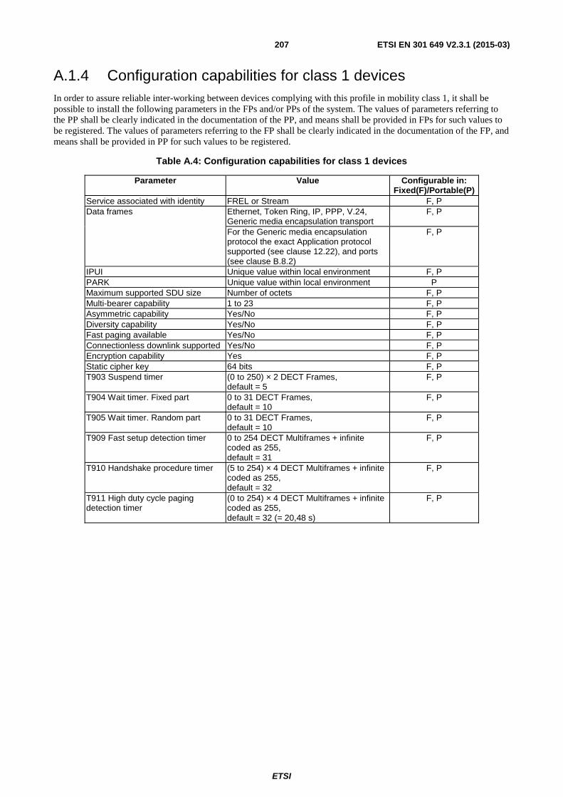
ETSI
ETSI EN 301 649 V2.3.1 (2015-03)207
A.1.4 Configuration capabilities for class 1 devices In order to assure reliable inter-working between devices complying with this profile in mobility class 1, it shall be possible to install the following parameters in the FPs and/or PPs of the system. The values of parameters referring to the PP shall be clearly indicated in the documentation of the PP, and means shall be provided in FPs for such values to be registered. The values of parameters referring to the FP shall be clearly indicated in the documentation of the FP, and means shall be provided in PP for such values to be registered.
Table A.4: Configuration capabilities for class 1 devices
Parameter Value Configurable in: Fixed(F)/Portable(P)
Service associated with identity FREL or Stream F, P Data frames Ethernet, Token Ring, IP, PPP, V.24,
Generic media encapsulation transport F, P
For the Generic media encapsulation protocol the exact Application protocol supported (see clause 12.22), and ports (see clause B.8.2)
F, P
IPUI Unique value within local environment F, P PARK Unique value within local environment P Maximum supported SDU size Number of octets F, P Multi-bearer capability 1 to 23 F, P Asymmetric capability Yes/No F, P Diversity capability Yes/No F, P Fast paging available Yes/No F, P Connectionless downlink supported Yes/No F, P Encryption capability Yes F, P Static cipher key 64 bits F, P T903 Suspend timer (0 to 250) × 2 DECT Frames,
default = 5 F, P
T904 Wait timer. Fixed part 0 to 31 DECT Frames, default = 10
F, P
T905 Wait timer. Random part 0 to 31 DECT Frames, default = 10
F, P
T909 Fast setup detection timer 0 to 254 DECT Multiframes + infinite coded as 255, default = 31
F, P
T910 Handshake procedure timer (5 to 254) × 4 DECT Multiframes + infinite coded as 255, default = 32
F, P
T911 High duty cycle paging detection timer
(0 to 254) × 4 DECT Multiframes + infinite coded as 255, default = 32 (= 20,48 s)
F, P

ETSI
ETSI EN 301 649 V2.3.1 (2015-03) 208
A.1.5 Determination of the <<SETUP CAPABILITY>> IEs to be used for a connection Table A.5: <<SETUP CAPABILITY>> IE to be used (default or sent) on PT/FT side
FT supports Class 2 only Class 4 only Class 3, 4
only Class 2, 4
only Class 2, 3, 4 Class 2 only Class 4 only Class 3, 4 only
Class 2, 4 only Class 2, 3, 4
does FT send IE ? YES NO
PT supports
does PT send IE ?
Class 2 only
YES
c2 connection: sent IEs
NA c2 connection: sent IEs
c2 connection: - PT: sent IE - FT: default IE
NA c2 connection: - PT: sent IE - FT: default IE
Class 4 only
NA
c4 connection: sent IEs
NA
c4 connection: default IEs
Class 3, 4 only
c3 or c4 connection:
sent IEs
c3 or c4 connection:
sent IEs
c3 or c4 connection: default IEs
c3 or c4
connection: default IEs
Class 2, 4 only
c2 connection: sent IEs
c2 or c4
connection: sent IEs
c2 connection: - PT: sent IE - FT: default IE
c2 connection: - PT: sent IE - FT: default IE c4 connection: - default IEs
Class 2, 3, 4
c3 or c4 connection:
sent IEs
c2, c3 or c4 connection:
sent IEs
c3 or c4 connection:
default IEs
c2 connection: - PT: sent IE - FT: default IE c3 or c4 connection: - default IEs

ETSI
ETSI EN 301 649 V2.3.1 (2015-03) 209
FT supports Class 2 only Class 4 only Class 3, 4
only Class 2, 4
only Class 2, 3, 4 Class 2 only Class 4 only Class 3, 4 only
Class 2, 4 only Class 2, 3, 4
does FT send IE ? YES NO
PT supports
does PT send IE ?
Class 2 only
NO
c2 connection: - PT: default IE - FT: sent IE
NA c2 connection: - PT: default IE
- FT: sent IE
c2 connection: default IEs NA c2 connection:
default IEs
Class 4 only
NA
c4 connection: default IEs
NA
c4 connection: default IEs
Class 3, 4 only
c3 or c4 connection:
default IEs
c3 or c4 connection: default IEs
c3 or c4 connection: default IEs
c3 or c4
connection: default IEs
Class 2, 4 only
c2 connection: - PT:default IE - FT:sent IE c4 connection: - default IEs
c2 connection: default IEs
c2 or c4 connection: - default IEs
Class 2, 3, 4
c3 or c4 connection: default IEs
c2 connection: - PT: default IE - FT: sent IE c3 or c4 connection: - default IEs
c3 or c4 connection: default IEs
c2, c3 or c4 connection: - default IEs
NOTE 1: Each device (PT or FT) knows supported management classes on the other side thanks to capability bits. When several classes are supported on both sides, the DPRS management class used is determined at connection time among commonly supported classes.
NOTE 2: c2, c3, and c4 are an abridged form for Class 2, Class 3 and Class 4. NOTE 3: Except when otherwise stated, the connection uses either default IEs on both sides, or sent IEs on both sides. NOTE 4: When a default IE is used, the default IE to be considered is the one associated in the present document with the class used at connection time. NOTE 5: If a device sends an IE, it shall always be for all supported classes. NOTE 6: For class 2 (but not for class 3 or 4), it is allowed to combine the default IE used for one side, with the IE sent from the other side. See clause 12.8.2.4
'Simultaneous use of both mechanisms'.

ETSI
ETSI EN 301 649 V2.3.1 (2015-03) 210
A.2 Default coding of <<IWU-ATTRIBUTES>>, << CALL-ATTRIBUTES >>, << CONNECTION-ATTRIBUTES >>, << WINDOW SIZE >>, << TRANSIT DELAY >> and << SETUP-CAPABILITY >> information elements for DPRS Basic Services
See ETSI EN 300 175-5 [5], clause 7.6.4 for definition and coding of the IE << Basic Services >>.
NOTE: Currently there are two DPRS basic services related to Light Data Services with codes "1001"B and "1010"B.
In the case of basic services related to DPRS, the setup attributes shall have default values as given below.
A.2.1 Default setup attributes for basic service "light data service, with Class 4 DPRS management" (code "1001"B)
See ETSI TS 102 527-4 [i.2] for the definition of Light Data Service.
Table A.6: Void
Table A.7: Default coding for << CALL-ATTRIBUTES >> information element
Octet Information element field Field Value 3 Coding standard DECT standard Network layer attributes DPRS Class 4 ("0110"B)
4 C-plane class Class A; shared C-plane routing CS only
5 U-plane symmetry Symmetric LU identification LU10
6 U-plane class Class 2; SELective U-plane frame type FU10a/c
Table A.8: Default coding for << CONNECTION-ATTRIBUTES >> information element
Octet Information element field Field Value 3 < Symmetry > Symmetric only connection < Connection identity > Unknown
4 < Maximum bearers P ⇒ F direction > 1 4a < Minimum bearers P ⇒ F direction > 1 4b < Maximum bearers F ⇒ P direction > 1 4c < Minimum bearers F ⇒ P direction > 1 5 < Slot type> Long slot; j = 640 < MAC service P ⇒ F > IPM; (IP error detect, multisubfield)
5a < MAC service F ⇒ P > IPM; (IP error detect, multisubfield)
6 < CF-channel attributes P ⇒ F > CF never (CS only)
< MAC packet life time P ⇒ F > Not applicable 6a < CF-channel attributes F ⇒ P> CF never (CS only)
< MAC packet life time F ⇒ P> Not applicable 7 < A attributes > 2-level < B attributes > 2-level

ETSI
ETSI EN 301 649 V2.3.1 (2015-03) 211
Table A.9: Default coding for << WINDOW SIZE >> information element
Octet Information element field Field Value 3 ext3 0 < Window size value (PT ⇒ FT) > '0000000'B
3a ext3a 1 < Window size value (PT ⇒ FT), continued > '0100000'B (=32)
NOTE: FT => PT values are equal to PT => FT values (octet group 4 omitted). Extensions of octets 3b, 3c, 4b and 4c in ETSI EN 300 175-5[5], clause 7.7.43 are not used.
Table A.10: Default coding for << TRANSIT-DELAY >> information element
Octet Information element field Field Value 3 <upstream (P ⇒ F) delay> 0 4 < downstream (F ⇒ P) delay> 0

ETSI
ETSI EN 301 649 V2.3.1 (2015-03) 212
Table A.11: Default values assumed within the IE << SETUP-CAPABILITY >>
Information element Field within the information element
Standard values within the
field/information element
Normative action/comment
<< Set-up capability >> < ext3 > 0 < Protocol discriminator > 001 DPRS. < Setup > 01 No fast setup supported (only indirect
setup is supported), i.e. Normal setup. < Page > 01 Normal paging only. < ext4 > 1 < Service_settings_1 > 0001000 Summary of used values; see below xxxxxx0 IP_error_correct not supported.
xxxxx0x Does not allow suppression of bearer quality messages for asymmetric connection (ETSI EN 300 175-3 [3], clause 7.3.5.4) only if all Q2 bits are = 1.
xxxx0xx Does not allow suppression of bearer quality messages for asymmetric connection (ETSI EN 300 175-3 [3], clause 7.3.5.4) in any case.
xx01xxx No simultaneous voice and DPRS call supported, but switching procedure supported.
00xxxxx No multiple simultaneous DPRS connections supported.
< Parameter_settings_1 > N/A Class 2 only bitmap octet; shall be ignored for Class 4.
< Parameter_settings_2 > N/A Class 3 only bitmap octet; shall be ignored for Class 4.
T903 (6) N/A Class 2 only; Irrelevant for Class 4. T904 (6a) N/A Class 2 only; Irrelevant for Class 4. T905 (6b) N/A Class 2 only; Irrelevant for Class 4. T909 (6c) N/A Class 2 only; Irrelevant for Class 4. T910 (6d) N/A Class 2 only; Irrelevant for Class 4. T911 (6e) N/A Class 2 only; Irrelevant for Class 4. Bearer support 1st octet (6f) N/A Class 2 only; Irrelevant for Class 4. Bearers number upstream N/A Class 2 only; Irrelevant for Class 4. Bearer support 2nd octet
(6g) N/A Class 2 only; Irrelevant for Class 4.
Bearers number downstream
N/A Class 2 only; Irrelevant for Class 4.
T_910_Class_3 (6h) N/A Class 3 only; Irrelevant for Class 4. <Application protocol or
supported capability indicator 1>
"0000010"B HTTP limited set nr. 2 supported (as specified in clause B.8.3.4).
<Application protocol or supported capability indicator 2>
"0100001"B Application packet size of up to 1,5 kBytes supported in PT ⇒ FT direction (see note).
<Application protocol or supported capability indicator 3>
"0110011"B Application packet size of up to 12 kBytes supported in FT ⇒ PT direction (see note).
<Application protocol or supported capability indicator 4>
"1001010"B Support of "Simplified single-context Interworking to External Networks (or to an application proxy)" procedure (clause B.8.4.3).
NOTE: The default value for the application protocol indicator 2 indicating maximum accepted application packet size is different in both directions. It shall be assumed that both peers are able to handle packets of up to 12 kBytes in downstream direction and up to 1,5 kBytes in upstream direction.

ETSI
ETSI EN 301 649 V2.3.1 (2015-03) 213
A.2.2 Default setup attributes for basic service "light data service with Class 3 DPRS management" (code "1010"B)
See ETSI TS 102 527-4 [i.2] for the definition of Light Data Service.
Table A.12: Void
Table A.13: Default coding for << CALL-ATTRIBUTES >> information element
Octet Information element field Field Value 3 Coding standard DECT standard Network layer attributes DPRS Class 3 ("0011"B)
4 C-plane class Class A; shared C-plane routing CS only
5 U-plane symmetry Symmetric LU identification LU10
6 U-plane class Class 2; SELective U-plane frame type FU10a/c
Table A.14: Default coding for << CONNECTION-ATTRIBUTES >> information element
Octet Information element field Field Value 3 < Symmetry > Symmetric only connection < Connection identity > Unknown
4 < Maximum bearers P⇒F direction > 1 4a < Minimum bearers P⇒F direction > 1 4b < Maximum bearers F⇒P direction > 1 4c < Minimum bearers F⇒P direction > 1 5 < Slot type> Long slot; j = 640 < MAC service P ⇒ F > IPM; (IP error detect, multisubfield)
5a < MAC service F ⇒ P > IPM; (IP error detect, multisubfield)
6 < CF-channel attributes P ⇒ F > CF never (CS only)
< MAC packet life time P ⇒ F > Not applicable 6a < CF-channel attributes F ⇒ P> CF never (CS only)
< MAC packet life time F ⇒ P> Not applicable 7 < A attributes > 2-level < B attributes > 2-level
Table A.15: Default coding for << WINDOW SIZE >> information element
Octet Information element field Field Value 3 ext3 0 < Window size value (PT ⇒ FT) > '0000000'B
3a ext3a 1 < Window size value (PT ⇒ FT), continued > '0100000'B (=32)
NOTE: FT => PT values are equal to PT => FT values (octet group 4 omitted). Extensions of octets 3b, 3c, 4b and 4c in ETSI EN 300 175-5 [5], clause 7.7.43 are not used.
Table A.16: Default coding for << TRANSIT-DELAY >> information element
Octet Information element field Field Value 3 <upstream (P ⇒ F) delay> 0 4 < downstream (F ⇒ P) delay> 0

ETSI
ETSI EN 301 649 V2.3.1 (2015-03) 214
Table A.17: Default values assumed within the IE << SETUP-CAPABILITY >>
Information element Field within the information element
Standard values within the
field/information element
Normative action/comment
<< Set-up capability >> < ext3 > 0 < Protocol discriminator > 001 DPRS. < Set-up > 01 No fast setup supported (only indirect
setup is supported), i.e. Normal setup. < Page > 01 Normal paging only. < ext4 > 1 < Service_settings_1 > 0001000 Summary of used values; see below xxxxxx0 IP_error_correct not supported.
xxxxx0x Does not allow suppression of bearer quality messages for asymmetric connection (ETSI EN 300 175-3 [3], clause 7.3.5.4) only if all Q2 bits are = 1.
xxxx0xx Does not allow suppression of bearer quality messages for asymmetric connection (ETSI EN 300 175-3 [3] clause 7.3.5.4) in any case.
xx01xxx No simultaneous voice and DPRS call supported, but switching procedure supported.
00xxxxx No multiple simultaneous DPRS connections supported.
< Parameter_settings_1 > N/A Class 2 only bitmap octet; shall be ignored for Class 4.
< Parameter_settings_2 > PT: 00000000 FT: 00000001
Class 3 only bitmap octet.
T903 (6) 0 Class 2 only; Irrelevant for Class 3. T904 (6a) 0 Class 2 only; Irrelevant for Class 3. T905 (6b) 0 Class 2 only; Irrelevant for Class 3. T909 (6c) 0 Class 2 only; Irrelevant for Class 3. T910 (6d) 94 Class 2 only; Irrelevant for Class 3 T911 (6e) N/A Class 2 only; Irrelevant for Class 3 Bearer support 1st octet (6f) N/A Class 2 only; Irrelevant for Class 3. Bearers number upstream N/A Class 2 only; Irrelevant for Class 3 Bearer support 2nd octet
(6g) N/A Class 2 only; Irrelevant for Class 3
Bearers number downstream
N/A Class 2 only; Irrelevant for Class 3
T_910_Class_3 (6h) PT:none, FT:94 Handshake procedure timer. FT value is the coding for 376 MF = 60,16 s.
<Application protocol or supported capability indicator 1>
"0000010"B HTTP limited set nr. 2 supported (as specified in clause B.8.3.4).
<Application protocol or supported capability indicator 2>
"0100001"B Application packet size of up to 1,5 kBytes supported in PT ⇒ FT direction (see note).
<Application protocol or supported capability indicator 3>
"0110011"B Application packet size of up to 12 kBytes supported in FT ⇒PT direction (see note).
<Application protocol or supported capability indicator 4>
"1001010"B Support of "Simplified single-context Interworking to External Networks (or to an application proxy)" procedure (clause B.8.4.3).
NOTE: The default value for the application protocol indicator 2 indicating maximum accepted application packet size is different in both directions. It shall be assumed that both peers are able to handle packets of up to 12 kBytes in downstream direction and up to 1,5 kBytes in upstream direction.

ETSI
ETSI EN 301 649 V2.3.1 (2015-03) 215
Annex B (normative): Interworking conventions for the Frame Relay (FREL) service
B.1 Scope of this annex This annex defines the Interworking conventions for Frame Relay (FREL) service. DPRS Frame Relay service may be used for the transport of the following protocols:
• IEEE 802.3 [13]/Ethernet;
• IEEE 802.5 [14] (Token Ring);
• Version 4 RFC 791 [15] or higher, Internet Protocol (IP);
• RFC 1661 [16], Point-to-Point Protocol (PPP).
Clauses B.1, B.2 and B.3 define a set of conventions applicable to the Frame Relay service in general, and clauses B.4 to B.7 define the specific conventions for each one of the transported protocols.
In addition clause B.8 defines the DPRS Generic media encapsulation transport which provides a means for transporting simultaneously the datagrams of various Application media protocols during one and the same DECT call utilizing the DPRS frame relay service.
B.1.1 Typical configuration for the Frame Relay service The typical configuration for Frame Relay service is shown in figure B.1.
NWK
MAC
IWU
PHY
NWK
IWU
DECT terminal DECT terminal
FREL applicationor interface
IWF
DLC-U(LU10)
IWF
MAC
PHY
FREL applicationor interface
DLC-C DLC-U(LU10)
DLC-C
Figure B.1: Reference configuration for Frame Relay (FREL) service, including interworking to connection-oriented or connectionless networks
Mobility class 2 equipment provides a full DECT C-plane, while for mobility class 1 equipment, the C-plane is replaced by a Closed User Group administration.

ETSI
ETSI EN 301 649 V2.3.1 (2015-03) 216
The specific encapsulation interworking functions are defined in the other clauses of this annex, and are depending on the transported connectionless or connection-oriented protocol. The implementation of the external network used to transport the service protocol outside the DECT system is outside the scope of this profile.
B.2 Specific codings for mobility class 2
B.2.1 IWU-ATTRIBUTES information element coding Mobility class 2 equipment, implementing the Interworking Units described in this annex, shall use the following IWU-ATTRIBUTES information element coding.
Bit: 8 7 6 5 4 3 2 1 Octet: 0 << IWU-ATTRIBUTES >> 1 Length of Contents (L) 2 1 CodeStd Profile 3 0 1 0 0 0 0 0 1 Negotiation indicator Profile subtype 4 0 Maximum SDU size PT ⇒ FT
(Most significant 7 bits) 5
0/1 Maximum SDU size PT ⇒ FT (Least significant 7 bits)
5a
0 Maximum SDU size FT ⇒ PT (Most significant 7 bits)
5b (optional)
1 Maximum SDU size FT ⇒ PT (Least significant 7 bits)
5c (optional)
0/1 Profile subtype attributes 6 (optional) 1 Profile subtype attributes 6x (optional)
Figure B.2: IWU-ATTRIBUTES information element coding
Code std (octet 3): Bits 7 6 Meaning 0 1 Profile defined code.
Profile (octet 3): Bits 5 4 3 2 1 Meaning 0 0 0 0 0 DPRS: Frame Relay services.
Negotiation indicator (octet 4): Bits 7 6 5 Meaning 0 0 0 Negotiation not possible. 0 1 0 Peer attribute negotiation. 1 0 0 Exchanged attribute negotiation. 1 1 0 Exchanged attribute negotiation and Peer attribute negotiation. All other values are reserved.
Profile subtype (octet 4): Bits 4 3 2 1 Meaning 0 0 0 0 IEEE 802.3 [13]/Ethernet (see clause B.4). 0 0 0 1 IEEE 802.5 [14] (see clause B.5). 0 0 1 0 Internet Protocol (IP) (see clause B.6). 0 1 0 0 Point-to-Point Protocol (see clause B.7). 1 0 0 0 DPRS Generic Media Encapsulation (see clause B.8). All other values are reserved.
Maximum SDU size PT ⇒ FT (octets 5 and 5a): This 14-bit word represents the natural binary coding of the maximum SDU length in units of eight octets used for data transmission, with the least significant bit in position 1 of octet 5a. This value applies in both directions if octets 5b and 5c are not present. Otherwise, this value applies for the upstream direction.
The maximum possible value is "1111111" (octet 5) "1111100" (octet 5a), coding a SDU length of 131 040 bytes (16 380 × 8).

ETSI
ETSI EN 301 649 V2.3.1 (2015-03) 217
The following codes have special values:
• "1111111" (octet 5) "1111101" (octet 5a) ⇒ indicates an SDU length longer than 131 040 bytes, but finite.
• "1111111" (octet 5) "1111110" (octet 5a) ⇒ is reserved for further development and should not be used.
• "1111111" (octet 5) "1111111" (octet 5a) ⇒ indicates an infinite SDU length.
NOTE: The term "infinite SDU" indicates that the data flow is handled as a stream.
Maximum SDU size FT ⇒ PT (octets 5b and 5c, optional): If these octets are present, this 14-bit word represents the natural binary coding of the maximum SDU length in units of eight octets used for data transmission in the FT ⇒ PT direction, with the least significant bit in position 1 of octet 5c.
The same special codes of octets 5/5a apply.
B.2.1.1 Profile subtype attributes (octet group 6) of IWU-ATTRIBUTES information element
The octet group 6 of IWU-ATTRIBUTES information element shall have a profile subtype specific meaning.
The profile subtype attributes octet group is optional. If it is not present, the following assumptions shall be taken:
• For IEEE 802.3 [13] and IEEE 802.5 [14] (clauses B.4 and B.5) it shall be understood as SIP connectionless
downlink not used.
• For IP (clause B.6), it shall be understood as IP version 4 (RFC 791 [15]) and no PDP address is passed in the message.
• In the case of the DECT generic media encapsulation protocol this octet group is mandatory unless a basic service has been invoked in the setting of the connection. See clause A.2 for the default values that shall be understood when this group is not present and a basic service has been invoked.
B.2.1.1.1 IEEE 802.3/Ethernet
Bit: 8 7 6 5 4 3 2 1 Octet: 1 SIP 0 0 0 0 0 0 6 (optional) Spare
Figure B.3: Ethernet
SIP bit: This bit indicates if the connectionless downlink service SIP is being used (see clause B.4.2.1).
Bit 7 Meaning 1 SIP connectionless downlink is being used.
0 SIP connectionless downlink not used.
B.2.1.1.2 IEEE 802.5 (Token-Ring)
Bit: 8 7 6 5 4 3 2 1 Octet: 1 SIP 0 0 0 0 0 0 6 (optional) Spare
Figure B.4: Token Ring
SIP bit (bit 7 of octet 6): This bit indicates if the connectionless downlink service SIP is being used (see
clause B.5.2.2).
Bit 7 Meaning 1 SIP connectionless downlink is being used.
0 SIP connectionless downlink not used.

ETSI
ETSI EN 301 649 V2.3.1 (2015-03) 218
B.2.1.1.3 Internet Protocol (IP)
In the case of Internet protocol (IP) Interworking, the profile subtype is used to indicate the IP version and, optionally, to pass an IP address. This facility may be used, for instance, for dynamic IP address allocation at the beginning of the virtual call.
Bit: 8 7 6 5 4 3 2 1 Octet: 0/1 IP version Spare ("00000") 6 PDP address, byte 1 (most significant) 6a PDP address, byte 2 6b PDP address, byte 3 6c PDP address, byte 4 (last and less significant if IPv4) 6d PDP address, byte 5 (only if IPv6) 6e PDP address, byte 6 (only if IPv6) 6f PDP address, byte 7 (only if IPv6) 6g PDP address, byte 8 (only if IPv6) 6h PDP address, byte 9 (only if IPv6) 6i PDP address, byte 10 (only if IPv6) 6j PDP address, byte 11 (only if IPv6) 6k PDP address, byte 12 (only if IPv6) 6l PDP address, byte 13 (only if IPv6) 6m PDP address, byte 14 (only if IPv6) 6n PDP address, byte 15 (only if IPv6) 6o PDP address, byte 16 (only if IPv6, less significant) 6p
Figure B.4a: Internet Protocol IPv4 or IPv6
IP version: bits 6 and 7 of octet 6.
Bit 7 6 Meaning 0 1 IP version 4 (RFC 791 [15]). 1 0 IP version 6 (RFC 2460 [34]). All other values reserved.
Spare: bits 1 to 5 of octet 6.
Spare bits are reserved for future use and shall be set to "00000".
PDP address (IP address): octets 6a to 6d if IPv4, or 6a to 6p if IPv6.
If IP type is IPv4, then the 4 following octets 6a to 6d may be used to transfer an IP address. This is indicated by bit 8 of octet 6: if bit 8= 0, then octets 6a to 6d follows, if bit 8 = 1, then there is no address.
The four bytes set to "0", means blank address. This may be used to request an IPv4 address in the return message.
If IP type is IPv6, then the 16 following octets 6a to 6p may be used to transfer an IPv6 address. This is indicated by bit 8 of octet 6: if bit 8= 0, then octets 6a to 6p follows, if bit 8 = 1, then there is no address.
The 16 bytes set to "0", means blank address. This may be used to request an IPv6 address in the return message.
In both cases, most significant octet of the address is codec in octet 6a and less significant byte in last octet. Bits within octets are codec with less significant bit in bit 1 of each octet.
B.2.1.1.3.1 Dynamic IP address allocation
The allocation by the network of Dynamic IP addresses can be done as follows.
The PP starts a PDP context (outgoing call) sending the IWU-attributes IE with the 4 bytes of address (IPv4) set to "0". The FP may return an IP address in the response message.
NOTE: This method is analogue to GPRS.
If the PDP context is started by the FP (incoming call), then the allocated IP address may be transmitted within IWU-attributes in the CC-setup message.

ETSI
ETSI EN 301 649 V2.3.1 (2015-03) 219
B.2.1.1.4 DPRS Generic media encapsulation
For DPRS Generic media encapsulation, the following set of octets shall be inserted in octet 6 group for each D-GMEP context that is being created or released in the C-plane procedure that is using the << IWU-Attributes >> IE. If several contexts are created and/or released in the operation, several sets shall be inserted (up to four).
Bit: 8 7 6 5 4 3 2 1 Octet: 0/1 Operation code Optional groups CH bit Spare ("00") 6 seq Generic Media context indicator (GMCI) 6a Application protocol identifier (m.s.byte) 6b Application protocol identifier (l.s.byte) 6c Optional control group
6d (opt)
... 6o (opt)
Figure B.4b: DECT generic media encapsulation control set
NOTE: GMEP instances are called "contexts". Each context will usually transport a single protocol. Several contexts may be used to transport different protocols, or different instances (contexts) of the same protocol.
For each context, a D-GMEP control set shall be used. Each control set may have from 4 octets to 16 octets depending of options. Several control sets of variable length may appear in one << IWU-Attributes >> IE.
The maximum number of control sets in one signalling message shall be limited to FOUR (4) to limit the maximum size of the messages. It is possible to add additional contexts to the connection by means of the Service Change feature (DPRS-N.35) that has to be implemented if more than four instances of D-GMEP are to be multiplexed in one DPRS virtual connection.
B.2.1.1.4.1 Description of the different fields:
D-GMEP control set first octet (octet 6)
Extension Bit: bit 8, octet 6.
Bits 8 Meaning 0 Indicates that there is another control set after this one. Therefore another octet 6 follows the last octet of
this control set. 1 This is the last D-GMEP control set.
Operation code: bits 6 and 7, octet 6.
Describes the operation to be done. The possible codes are:
Bits 7 6 Meaning 0 1 Create one D-GMEP context (bidirectional) and adds it to the connection. 1 0 Release a D-GMEP context from the connection. All other values reserved.
NOTE 1: In virtual call setup procedures, only the code "01" may be used. The code "10" may only be used in the Service Change procedure.
Optional control groups indicator: bits 4 and 5, octet 6.
Indicates if there is an optional group of control octets after octet 6c, and which one. The possible values are the following:
Bits 5 4 Meaning 0 0 There are no optional control octets. 0 1 The control group for interworking to TCP/UDP/IP networks is present (see clause B.2.1.1.4.2). It
indicates that there are 12 octets 6d to 6o after octet 6c with the meaning described in clause B.2.1.1.4.2.
The operation code "Remove" ("10") shall not use optional control groups, and bits 4 to 5 shall be coded to "00".

ETSI
ETSI EN 301 649 V2.3.1 (2015-03) 220
Chop indicator bit: bit 3, octet 6.
Indicates that it is allowed to segment (chop) the application packet into several Interworking packets, that will become DLC SDUs.
Bits 3 Meaning 0 Chopping not allowed 1 Chopping allowed
Spare bits: bits 1 and 2, octet 6.
Bits 1 and 2 of octet 6 are reserved for further development and shall be set to "0".
D-GMEP control set second octet (octet 6a): This octet is also mandatory in each control set.
Sequence numbering Bit: (bit 8, octet 6a).
Bits 8 Meaning 0 Indicates that this D-GMEP context does not require sequence numbers. 1 Indicates that this D-GMEP context requires sequence numbers.
If this bit is set to 1, then the U-plane packets of this D-GMEP context shall be sequence numbered in the second octet of each U-plane packet (see figure B.8 in clause B.8.2).
NOTE 2: The U-plane packets (or Interworking packets) will become SDUs when passed to the DLC layer.
D-GMEP context identifier: bits 1 to 7, octet 6a.
These 7 bits carry the D-GMEP context identifier that shall be used in octet 1 of the U-plane packets (see figure B.8 in clause B.8.2).
The D-GMEP context identifier is an arbitrary number allocated by the FP at the context creation time. In PT initiated virtual call setups the number shall be set to "0000000" in the request message and the allocated value shall be returned by the FT. The same applies to PT initiated Service change (DPRS-N.35) adding new contexts.
In Service change (DPRS-N.35) requesting the removal of contexts (operation "10"), the real value shall be present in all messages.
D-GMEP protocol identifier: octets 6b and 6c.
These two octets are mandatory in each control set.
They indicate the protocol to be transported over the D-GMEP instance, according to the codes listed in clause B.8.3.
B.2.1.1.4.2 Optional control octets
Optional group for TCP/UDP/IP interworking: octets 6d to 6o.
This optional group for TCP/UDP/IP interworking may be used when the FP implements an interworking to an IP network. By using this group, it is possible to map each D-GMEP context to a connection/context over an external TCP/IP connection or UDP/IP context at the FP, and controlling the fields of the external TCP/UDP/IP datagrams used when transmitting the data of each D-GMEP context.
NOTE 1: The use of this control set is an option. Application profiles may define alternative mechanisms for the control of external TCP/UDP/IP communications.
The optional group is composed of 12 octets. If used, all octets described shall be present.
The total length of the control set with this option shall be 16 octets.
By using this group, the PT is indicating the FT that it should establish a TCP/IP connection or an UDP/IP context over an external Internet network, and map the packets transported over the D-GMEP context to such TCP connection or UDP context.
The connection shall be TCP/IP if the Sequence numbering Bit (bit 8, octet 6a) is set to 1. If the Sequence numbering Bit (bit 8, octet 6a) is set to 0, then the IP communication shall be UDP/IP.

ETSI
ETSI EN 301 649 V2.3.1 (2015-03) 221
In protocols with specific descriptions (see clause B.8.3), this rule shall be also fulfilled, unless specific special rules are provided in the description.
NOTE 2: Currently there are no such special rules.
When the optional control group for interworking to TCP/IP networks used, then the control set has the following composition.
Bit: 8 7 6 5 4 3 2 1 Octet: 0/1 Operation code Optional groups CH Spare ("00") 6 seq GMEP context indicator (GMCI) 6a Application protocol D-GMEP identifier 6b Application protocol D-GMEP identifier 6c IP source address (m.s.byte) 6d IP source address 6e IP source address 6f IP source address (l.s.byte) 6g IP destination address (m.s.byte) 6h IP destination address 6i IP destination address 6j IP destination address (l.s.byte) 6k TCP / UDP source port number (m.s.byte) 6l TCP / UDP source port number (l.s.byte) 6m TCP / UDP destination port number (m.s.byte) 6n TCP / UDP destination port number (l.s.byte) 6o
Figure B.4c: DECT generic media encapsulation, including the optional group
for interworking to TCP/IP networks
Description of the different optional fields:
Source IP address: octets 6d to 6g.
These 4 octets carry the IP address to be used by the FP as source address in an external TCP/IP connection or UDP/IP context, for all packets belonging to the D-GMEP context.
Most significant bit shall be bit 8 of octet 6d and less significant bit shall be bit 1 of octet 6g.
Unless special provisions are given in the application profile, these octets shall be left as "0.0.0.0" in the request message of a PT initiated context creation (either at call setup or at service change) and the value shall be returned by the FT.
Destination IP address: (octets 6h to 6k).
These 4 octets carry the destination IP address to be inserted by the FP in an external TCP/IP connection or UDP/IP context, for all packets belonging to the D-GMEP context.
Most significant bit shall be bit 8 of octet 6h and less significant bit shall be bit 1 of octet 6k.
Source TCP/UDP port: octets 6l to 6m.
These 2 octets carry the source TCP or UDP port number to be used by the FP in an external TCP/IP connection or UDP/IP context, for all packets belonging to the D-GMEP context.
Most significant bit shall be bit 8 of octet 6l and less significant bit shall be bit 1 of octet 6m.
Unless special provisions are given in the application profile, these octets shall be left as "0.0" in the request message of a PT initiated context creation (either at call setup or at service change) and the number shall be allocated and returned by the FT.
Destination TCP/UDP port: octets 6n to 6o.
These 2 octets carry the destination TCP or UDP port number to be used by the FP in an external TCP/IP connection or UDP/IP context, for all packets belonging to the D-GMEP context.
Most significant bit shall be bit 8 of octet 6n and less significant bit shall be bit 1 of octet 6o.

ETSI
ETSI EN 301 649 V2.3.1 (2015-03) 222
This parameter shall be set with the port number that the far end host is listening to.
NOTE 3: This number is usually, but not always, equal to the "well-known" number of the Internet application protocol. The real number the far end host is listening to should be placed here.
B.2.1.1.4.3 D-GMEP Protocol identifier codes
The protocol identifier code, as described in clause B.8.3, shall be inserted in octets 6b/6c for identification of the transported protocol. Most significant bit is bit 8 of octet 6b.
See clause B.8.3.2 for the codes of protocols with specific description. For all other well-known protocols, the IETF well-known port number shall be used.
NOTE 1: The IETF well-known port number should be used here as identifier of the protocol, independently of what is the port number to be used in the Internet connection.
EXAMPLE: For an HTTP (full HTTP) communication (well-know port number 80) to a far end-server that is listening at port 1080, the value "80" should be coded here to identify the protocol and the value "1080" should be used in the TCP-UDP/IP optional octets (octets 6n, 6o), to indicate the destination TCP port.
NOTE 2: In addition to the provisions given in the present clause regarding the coding of the << IWU ATTRIBUTES >> at call setup or service change, all DECT terminals supporting Generic media encapsulation are requested to indicate the supported Application Protocols, and other related capabilities, at subscription and location registration using the << SETUP-CAPABILITY >> information element as described in clause 12.22.
B.2.2 IWU attributes implemented Table B.1: IWU-ATTRIBUTES information element support status
Supported parameters Field no. Name of fields Reference Support Values
Allowed Supported 1 ID of IWU attributes of
variable length M 18
2 Length of Contents (L) M 0 to 255 4,5 3 Coding standard M 1 1 3 Profile M 0 0 4 Negotiation indicator M 0,2,4,6 0,2 4 Profile subtype B.2.1 M 0 to 15 0, 1, 2, 4, 8
5, 5a Maximum SDU size (PT ⇒ FT or both ways)
B.2.1 M 0 to 16 383 (equivalent to 0 to 131 064 octets)
191 to 16 383 (equivalent to 1 528 to 131 064 octets)
5b, 5c Maximum SDU size (FT ⇒ PT, optional)
B.2.1 O 0 to 16 383 (equivalent to 0 to 131 064 octets)
191 to 16 383 (equivalent to 1 528 to 131 064 octets)
6 SIP Service B.2.1.1.1, B.2.1.1.2
C.B11 0, 1 0,1
6 IP type B.2.1.1.3 C.B12 1, 2 1,2 6a, 6d IP address IPv4 B.2.1.1.3 C.B13 0 to
255.255.255.255 0 to 255.255.255.255
6a, 6p IP address IPv6 B.2.1.1.3 C.B14 0 to 2128 0 to 2128 6, 6x Application protocol control
set B.2.1.1.3 C.B15 All (see note) All (see note)
C.B11: IF profile subtype is IEEE 802.3 [13]/Ethernet or IEEE 802.5 [14] (Token-Ring) THEN O, ELSE X. C.B12: IF profile subtype is IP THEN M ELSE I. C.B13: IF profile subtype is IP and IPtype =IPv4 THEN O ELSE I. C.B14: IF profile subtype is IP and IPtype =IPv6 THEN O ELSE I. C.B15: IF profile subtype is DECT generic media encapsulation, THEN M ELSE I. NOTE: See clause B.2.1.1.4.

ETSI
ETSI EN 301 649 V2.3.1 (2015-03) 223
B.3 Generic Frame Relay service interworking conventions
The provisions of this clause shall apply to all applications of the Frame Relay service.
B.3.1 DLC U-plane service The Frame Relay service shall be transported by DLC LU10 (Enhanced Frame Relay service).
B.3.2 Transmission bit order All data frames shall always be transmitted as DECT DLC layer SDUs. The Most Significant Bit (MSB) of each octet shall be transmitted first and the Least Significant Bit (LSB) last.
NOTE: The implementer of a FREL interworking needs to bare in mind that some application protocols may submit octets being part of their packets of data to the IWF in reverse order, e.g. the transmission requirements for an Ethernet packet as stated in IEEE 802.3 [13]/Ethernet. LAN standards are LSB first.
B.3.3 Support of SDU size Any DECT equipment supporting any of the DPRS Frame Relay services defined in this annex shall be capable of supporting LU10 SDU frames of at least 1 528 octets. The equipment may optionally support larger SDUs.
In addition to that, any DECT equipment supporting DPRS Generic Interworking and the Light Data Services (see ETSI TS 102 527-4 [i.2]) shall be capable of supporting LU10 SDU frames in the downlink direction, of at least 12 koctets. The equipment may optionally support larger SDUs.
B.3.4 SIP connectionless downlink If the connectionless downlink service (SIP) is used, point-to-multipoint and broadcast packets may be transmitted by
the connectionless downlink service (SIP). These packets may also be transmitted by DECT connection-oriented
connections. If the service is not used, all traffic shall be transported by DECT connection-oriented connections.
B.4 IEEE 802.3/Ethernet The provisions of this clause shall apply if interworking to IEEE 802.3 [13]/Ethernet. LANs is provided.
NOTE: IEEE 802.3 [13] is also known as ISO/IEC 8802-3.
B.4.1 Typical configuration The typical configuration for this specific interworking convention shall be as defined in clause B.1, figure B.1 where the transported protocol is conform to IEEE 802.3 [13] or Ethernet [i.5].
B.4.1.1 Examples of implementation of the external transport network
Implementation of the external network used to transport the IEEE 802.3 [13] or Ethernet [i.5] frames outside the DECT system is out of the scope of the present document. Typical implementation will be the physical interface of the own IEEE 802.3 [13] or Ethernet. However, alternative implementations are also possible. Some examples of possible implementation and the associated interworking function are given in table B.2.

ETSI
ETSI EN 301 649 V2.3.1 (2015-03) 224
Table B.2: External network implementation examples
DPRS Service External transport network
Referenced standards IWU Function
Remarks
IEEE 802.3 [13] Ethernet [i.5]
IEEE 802.3 [13], Ethernet [i.5] (any PHY interface)
IEEE 802.3 [13]/ Ethernet [i.5]
Bridge Bridging in IWU.
IEEE 802.3 [13] Ethernet [i.5]
IEEE 802.3 [13], Ethernet [i.5] (any PHY interface)
IEEE 802.3 [13]/ Ethernet [i.5]
Routing/ NAT
Routing in IWU with option of NAT/PAT.
IEEE 802.3 [13] Ethernet [i.5]
Frame Relay Recommendation ITU-T Q.922 [i.13], RFC 1490 [i.10]
Bridge Bridging function (Ethernet switch) in IWU. IEEE 802.3 [13]/ Ethernet [i.5] over FR as RFC 1490 [i.10], bridged mode.
IEEE 802.3 [13] Ethernet [i.5]
Frame Relay Recommendation ITU-T Q.922 [i.13], RFC 1490 [i.10]
Switch Transparent mapping between each DECT terminal and each FR VC (multiple DLCIs in FR). IEEE 802.3 [13]/Ethernet [i.5] over FR as RFC 1490 [i.10], bridged mode.
IEEE 802.3 [13] Ethernet [i.5]
USB IEEE 802.3 [13], Ethernet [i.5] Recommendation ITU-T Q.922 [i.13], RFC 1490 [i.10]
Bridge A virtual IEEE 802.3 [13]/ Ethernet interface is transported over a USB interface to an application system.
B.4.2 Specific interworking conventions The conditions of clause B.3 shall be adhered to in addition to the following:
• the IEEE 802.3 [13]/Ethernet [i.5] MAC frame shall be transmitted as a single SDU beginning with the Destination Address up to (but not including) the FCS field, (see figure B.5);
• for IEEE 802.3 [13] MAC frames which contain Information fields of less than 46 octets and therefore have added PAD fields, the PAD fields shall not be transmitted, (see figure B.5);
• Ethernet MAC frames do not contain a Length field and do not provide sufficient information to establish the exact length of the Information field; therefore for Ethernet MAC frames which contain Information field with length of 46 octets the trailing octets containing all zeros shall not be transmitted (see figure B.5). Because removing of trailing octets with zeros may lead to removal parts of the information field as well, at the receiving side, on reception trailing octets with zeroes shall be added to sum up the Information field to 46 octets in length.
NOTE 1: At the receiving side recovery of any stripped-off fields not explicitly mandated to be recovered is an implementation issue.
NOTE 2: The requirements above do not impose any restriction on the IWF implementation. For example a designer may implement such Ethernet-to-IWF interworking where FCS bits are never calculated.
NOTE 3: See also RFC 1042 [i.12] and RFC 894 [i.11] for the encapsulation of Internet Protocol (IP) [15] over the IEEE 802.3 [13] or Ethernet [i.5] frames.
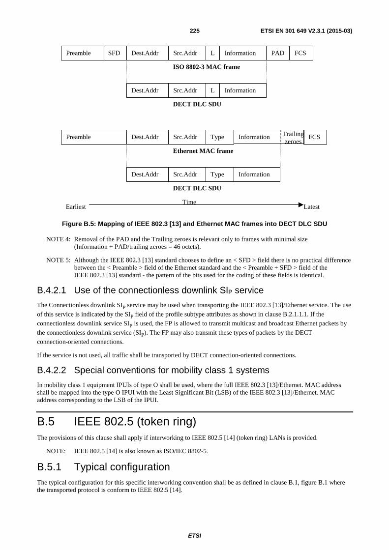
ETSI
ETSI EN 301 649 V2.3.1 (2015-03) 225
Preamble SFD Dest.Addr Src.Addr L Information PAD FCS
Dest.Addr Src.Addr L Information
Preamble Dest.Addr Src.Addr Type Information Trailingzeroes
FCS
Dest.Addr Src.Addr InformationType
ISO 8802-3 MAC frame
DECT DLC SDU
Ethernet MAC frame
DECT DLC SDU
EarliestTime
Latest
Figure B.5: Mapping of IEEE 802.3 [13] and Ethernet MAC frames into DECT DLC SDU
NOTE 4: Removal of the PAD and the Trailing zeroes is relevant only to frames with minimal size (Information + PAD/trailing zeroes = 46 octets).
NOTE 5: Although the IEEE 802.3 [13] standard chooses to define an < SFD > field there is no practical difference between the < Preamble > field of the Ethernet standard and the < Preamble + SFD > field of the IEEE 802.3 [13] standard - the pattern of the bits used for the coding of these fields is identical.
B.4.2.1 Use of the connectionless downlink SIP service
The Connectionless downlink SIP service may be used when transporting the IEEE 802.3 [13]/Ethernet service. The use
of this service is indicated by the SIP field of the profile subtype attributes as shown in clause B.2.1.1.1. If the
connectionless downlink service SIP is used, the FP is allowed to transmit multicast and broadcast Ethernet packets by
the connectionless downlink service (SIP). The FP may also transmit these types of packets by the DECT
connection-oriented connections.
If the service is not used, all traffic shall be transported by DECT connection-oriented connections.
B.4.2.2 Special conventions for mobility class 1 systems
In mobility class 1 equipment IPUIs of type O shall be used, where the full IEEE 802.3 [13]/Ethernet. MAC address shall be mapped into the type O IPUI with the Least Significant Bit (LSB) of the IEEE 802.3 [13]/Ethernet. MAC address corresponding to the LSB of the IPUI.
B.5 IEEE 802.5 (token ring) The provisions of this clause shall apply if interworking to IEEE 802.5 [14] (token ring) LANs is provided.
NOTE: IEEE 802.5 [14] is also known as ISO/IEC 8802-5.
B.5.1 Typical configuration The typical configuration for this specific interworking convention shall be as defined in clause B.1, figure B.1 where the transported protocol is conform to IEEE 802.5 [14].

ETSI
ETSI EN 301 649 V2.3.1 (2015-03) 226
B.5.1.1 Examples of implementation of the external transport network
Implementation of the external network used to transport the IEEE 802.5 [14] frames outside the DECT system is out of the scope of the present document. Typical implementation will be the physical interface of the own IEEE 802.5 [14]. However, alternative implementations are also possible. Some examples of possible implementation and the associated interworking function are given in table B.3.
Table B.3: Examples of external network implementations
DPRS Service External transport network
Referenced standards IWU Function
Remarks
IEEE 802.5 [14] IEEE 802.5 [14] IEEE 802.5 [14] Bridge Bridging function in IWU. IEEE 802.5 [14] Frame Relay Recommendation ITU-T
Q.922 [i.13], RFC 1490 [i.10] Bridge Bridging function in IWU.
IEEE 802.5 [14] over FR. IEEE 802.5 [14] Frame Relay Recommendation ITU-T
Q.922 [i.13], RFC 1490 [i.10] Switch Transparent mapping
between each DECT terminal and each FR VC. Multiple DLCIs in FR.
IEEE 802.5 [14] USB IEEE 802.5 [14], Recommendation ITU-T Q.922 [i.13], RFC 1490 [i.10]
Bridge A virtual IEEE 802.5 [14] interface is transported over a USB interface to an application system.
B.5.2 Specific interworking conventions The conditions of clause B.3 shall be adhered to in addition to the following:
• the IEEE 802.5 [14] MAC frame shall be transmitted as a single SDU beginning with the IEEE 802.5 [14] MAC Frame Control (FC) field and ending with the MAC Information field, (see figure B.6). At the receiving side recovery of the stripped-off fields is implementation issue;
• the token ring MAC Control frames as identified by the FC byte shall not be sent and shall be correctly inter worked with the token ring network. The Frame Status (FS) byte shall not be sent, (see figure B.6).
TimeEarliest Latest
Dest. Addr Information FCSSrc. Addr
ISO 8802.5 MAC frame
DECT DLC SDU
SDEL EDELRouting FSFCAC
Dest. Addr InformationSrc. Addr RoutingFC
Figure B.6: Mapping of IEEE 802.5 [14] MAC frames into DECT DLC SDU
B.5.2.1 Special conventions for mobility class 1 systems
In mobility class 1 equipment IPUIs of type O shall be used, where the full IEEE 802.5 [14] MAC address shall be mapped into the type O IPUI with the LSB of the IEEE 802.5 [14] MAC address corresponding to the LSB of the IPUI.
B.5.2.2 Use of the connectionless downlink SIP service
The Connectionless downlink SIP service may be used when transporting the IEEE 802.5 [14] (token ring) service. The
use of this service is indicated by Bit 7 of Octet 6 of << IWU-ATTRIBUTES >> shown in clause B.2.1.1.2. If the connectionless downlink service SIP is used, the FP is allowed to transmit point-to-multipoint and broadcast packets by
the connectionless downlink service (SIP). The FP may also transmit these types of packets by the DECT connection-
oriented connections.
If the service is not used, all traffic shall be transported by DECT connection-oriented connections.

ETSI
ETSI EN 301 649 V2.3.1 (2015-03) 227
B.6 Internet protocol The provisions of this clause shall apply if interworking to Internet Protocol (IP) version 4 (RFC 791 [15]) or higher is provided.
B.6.1 Typical configuration The typical configuration for this specific interworking convention shall be as defined in figure B.1 where the transport protocol is Internet Protocol version 4 (RFC 791 [15]), or higher.
B.6.1.1 Examples of implementation of the external transport network
Implementation of the external network used to transport the Internet Protocol outside the DECT system is out of the scope of the present document. Some examples of possible implementations and the associated Interworking function are given in table B.4.
Table B.4: Examples of external network implementations
DPRS Service
External transport network
Referenced standards IWU Function
Remarks
IP Connectionless LAN IEEE 802.3 [13], IEEE 802.5 [14] Router IP Routing function in IWU. IP Frame Relay Recommendation ITU-T
Q.922 [i.13], RFC 1490 [i.10] Router IP Routing function in IWU. IP
over FR as RFC 1490 [i.10], routed links.
IP Frame Relay Recommendation ITU-T Q.922 [i.13], RFC 1490 [i.10]
Switch Transparent mapping between each DECT terminal and a FR VC. Multiple DLCIs in FR. IP over FR as RFC 1490 [i.10], routed links.
IP ATM RFC 1483 [i.6] Router IP over ATM Adaptation Layer 5. IP Serial line PPP RFC 1661 [16],
RFC 1662 [17] Router IP Routing function in IWU. PPP
used only in external transport network.
B.6.2 Specific interworking conventions The conditions of clause B.3 shall be adhered to in addition to the following:
• IP datagrams shall be transmitted as a single SDU. The SDU contains the IP header followed immediately by the IP data. Since LU10 SDUs can be an arbitrarily short length there are no requirements for adding fill fields or padding.
B.6.2.1 Special conventions for mobility class 1 systems
In Mobility class 1 equipment IPUIs of type O shall be used.
B.7 Point-to-Point Protocol The provisions of this clause shall apply to transport data encapsulated using the Point-to-Point Protocol (PPP), as defined in RFC 1661 [16].
B.7.1 Typical configuration The typical configuration for this specific interworking convention shall be as defined in clause B.1, figure B.1. In this configuration the FP interworking transparently maps any PPP packet coming from a given DECT air interface packet-mode connection to a fixed virtual circuit at the Network interface.

ETSI
ETSI EN 301 649 V2.3.1 (2015-03) 228
B.7.1.1 Examples of implementation of the external transport network
Implementation of the external network used to transport the PPP outside the DECT system is out of the scope of the present document. Some examples of possible implementation are in table B.5.
Table B.5: Examples of external network implementations
DPRS Service
External transport network
Referenced standards
IWU Function Remarks
PPP Modem/PSTN RFC 1662 [17] Switch Mapping of C-plane signalling between DECT and PSTN possible.
PPP ISDN (circuit-switch) RFC 1618 [i.7] Switch Mapping of C-plane signalling between DECT and ISDN possible.
PPP Frame Relay RFC 1973 [i.8] Switch PPP over FR. PPP ATM RFC 2364 [i.9] Switch PPP over ATM AAL 5. PPP Tunnel over IP network L2TP (or PPTP) Switch Mapping of C-plane signalling
between DECT and L2TP possible.
B.7.2 Specific interworking conventions The conditions of clause B.3 shall be adhered to in addition to the following:
• The PPP packets, as defined in RFC 1661 [16] shall be transmitted directly as a single U-plane DLC layer SDU. The SDU contains the PPP "protocol field" header followed by the PPP data. The PPP framing, if used (e.g. the one defined in RFC 1662 [17] or other), shall not be transmitted over the DECT air interface.
• The maximum SDU packet size shall be 1 528 octets.
NOTE: At the receiving side recovery of any stripped-off fields is an implementation issue.
B.7.2.1 Special conventions for mobility class 1 systems
In Mobility class 1 equipment IPUIs of type O shall be used.
B.8 Interworking conventions for DPRS Generic Media Encapsulation transport mechanism
B.8.1 General This clause defines the interworking conventions for DPRS generic media encapsulation transport mechanism and protocol (D-GMEP) for transporting of protocols not covered by clauses B.3 to B.7 over DPRS. These protocols are typically (however not necessarily) application protocols.
A typical configuration example for DECT generic media encapsulation transport is shown in figure B.7.
D-GMEP allows multiplexation at Interworking level: different protocols and multiple instances of each protocol may be transported over the same DPRS virtual connection and DLC link instance.

ETSI
ETSI EN 301 649 V2.3.1 (2015-03) 229
IP
PHL
MAC
DLC- C
NWK - C
DLC-U
Applications
PHL
MAC
NWK -C TCP / UDP
FT PT
SMTP,HTTP,..
Access NWK Transport Protocols
DLC-C DLC -U
D-GMEP D-GMEP
IWU
Applications
SMTP, HTTP, SIP, FTP, RTSP, RTP,…
Figure B.7: Reference configuration for D-GMEP
B.8.2 Interworking Requirements D-GMEP implements an adaptation layer at interworking level with the following capabilities:
• Multiplexing of different flows.
• Insertion of a context identifier (GMCI).
• Segmentation (chopping) of large application packets into smaller SDUs (optional).
• Sequence numbering at Tx and sequence control at Rx (optional).
B.8.2.1 U-plane format and protocol elements
The DPRS Generic Media Encapsulation Protocol adds a header of one or two octets with the following information:
Context and context identifier (GMCI): To allow the handling of multiple simultaneous contexts of application protocols over a single DPRS connection, the adaptation layer assigns an identifier to each created context, called the "Generic Media context identifier (GMCI)".
The GMCI shall be assigned by the FP upon initiation of the context, and shall be used in the header of all U plane packets belonging to that context.
A context may be created at call setup, or may be added later to the call by means of a Service Change procedure (DPRS-N.35). Contexts may be also individually released during the call by means of a Service change procedure, or at call release that automatically removes all contexts.
Sequence number and "more" bit (optional): The second octet of the header is optional and includes a sequence number and an "M" (more) bit. If used, this octet allows the control of the sequence order and integrity at receiver side, and also the chopping of external protocol datagram into several smaller SDUs.
DPRS Frame Relay SDU: The header plus data unit shall constitute the DPRS Frame Relay SDU used in the DLC U-plane service.

ETSI
ETSI EN 301 649 V2.3.1 (2015-03) 230
The DPRS Generic Media Encapsulation protocol SDU shall be coded as follows:
Bit: 8 7 6 5 4 3 2 1 Octet: 0/1 Generic Media context identifier (GMCI) 1 M Sequence number (optional) 1a (opt) Application Data Unit (start) 2 ... ... Application Data Unit (end) 2n
Figure B.8: DPRS Generic Media Encapsulation protocol SDU
B.8.2.1.1 Description of the protocol elements of the U-plane header
D-GMEP U-plane header (octet group 1)
Sequence number indicator Bit: bit 8, octet 1.
Bits 8 Meaning 0 A sequence number and an "M" bit follows in octet 1a. 1 There is no octet 1a.
Generic Media context identifier (GMCI): bits 1 to 7, octet 1.
The GMCI is a unique number assigned at call setup (see clause B.2) by the FP used to identify the context of Generic Interworking Encapsulation. The relationship of this number with the protocol type and with port numbers used in external networks (f.i. TCP/UDP ports) is done at call setup or service change using C-plane. Up to 128 instances with sequence number and 128 without it may be identified.
More bit (bit 8, octet 1a): if the chopping option is used, this is the "M" (more) bit.
Bits 8 Meaning 0 This is the last segment (or the only one) of an application packet. 1 The next segment of the same application packet follows in next SDU.
If there is no chopping, this bit is reserved and shall be set to 0.
Sequence number: bits 1 to 7, octet 1a.
The sequence number allocated to this SDU within the GMEP context identified in octet 1 (through the GMCI).
Octet 1a is used only if bit 8 of octet 1 is set to 0.
NOTE: The recommended practice is adding the sequence number for protocols normally transported by TCP and not using it for protocols that are normally transported over UDP, over IP or directly over LAN frames.
Octet 1a and included sequence number shall be used if the chopping option is used.
B.8.2.2 SDU handling and interface to DLC
Consistently with other parts of the DECT standard, the term "SDU" shall be used for every formatted packet produced by the interworking layer and delivered to the DLC layer. "Application packet" refers to the external packet supplied to the interworking layer.
B.8.2.2.1 Transmitter side procedure
The D-GMEP allows the multiplexing of disjoint data flows named "contexts". Different contexts may carry different protocols or different instances of the same protocol.
For each data flow, the following operations shall be carried out independently.
If the chopping option is used (and only in this case):
• If the application (or other external protocol) datagram is larger than the maximum SDU size defined for the system minus 2 octets, it shall be split into several segments of length compatible with the maximum SDU size.

ETSI
ETSI EN 301 649 V2.3.1 (2015-03) 231
• Otherwise, each application packet shall be transported by one SDU.
If the chopping option is not used:
• Each application (or other external protocol) packet shall be transported by one SDU.
• The application packets shall be smaller than the maximum SDU size defined for the DPRS connection.
The header defined in clause B.8.2 shall be added to each application packet (if no chopping is used) or to each segment (if chopping is used).
The use of chopping and of sequence numbers shall be as defined by the C-plane in IWU-Attributes at time of context creation (either at call setup or at service change, see clause B.2.1.1.4). In any case, if the chopping option is used, then the use of the sequence number is mandatory.
When sequence numbers are used, an independent numbering sequence is used for each GMEP context.
The use of the sequence number shall be indicated by bit 8 of octet 1 of the U-plane header.
If multiple contexts of the GMEP are carried over the same DPRS connection, all flows shall be multiplexed.
NOTE 1: In case multiple contexts are multiplexed, the use of sequence numbers and of the chopping option is individual flow by flow.
NOTE 2: It is possible to use sequence numbers for some contexts and not using them for other contexts.
The multiplexed sequence of interworking packets shall be passed to the DLC LU10. Each interworking packet shall be one DLC SDU.
B.8.2.2.2 Receiver side procedure
SDUs shall be received from DLC LU10 service using the standard SDU delivery mode.
NOTE 1: However, if there is only one D-GMEP context, and it has sequence numbers, the use of the in-sequence SDU delivery produces exactly the same result.
The traffic for the different GMEP contexts shall be separated based on the GMCI label.
Data from every context shall be processed independently as follows:
For contexts with sequence number only:
• The receiver side shall ensure that there is no violation of sequence. In some cases, this may require buffering packets waiting for a missing packet with lower sequence. This process shall be done individually, context by context.
• However, when there is no chance to receive the missing packet, the delivering of packets shall continue.
NOTE 2: Correct implementation of this rule requires the interworking to be able to get information about the state of the DLC window.
NOTE 3: Therefore, there can be holes in the SDU sequence, but never a jump back.
If chopping option is used only:
• The interworking unit shall re-assemble segments of chopped application packets.
• If one segment of a chopped application packet is definitively missing, the interworking shall be able to signal this event to the user entity, which should act appropriately, or otherwise should discard the whole application packet.
• It is allowed to pass to the user entity, in-sequence segments of large application packets without waiting for the end boundary. However, in such a case, there should be a way to pass also an "abort" signal in case of impossibility to get the whole application packet.

ETSI
ETSI EN 301 649 V2.3.1 (2015-03) 232
For contexts without sequence number only:
• The buffering of packets to ensure sequence is not required. Therefore there may be sequence violations.
B.8.3 Application protocols
B.8.3.1 General
The Generic Media Encapsulation Interworking (D-GMEP) is intended for the transport of potentially any protocol directly on top of DPRS. The transportable protocols may belong to any of two categories:
1) protocols with a specific description in the present document; and
2) other well-known protocols, with well-known port numbers allocated by IETF for transport over TCP or UDP.
Each protocol will be identified by a protocol identifier number of 16 bits, which will be used in the C-plane call setup or service change procedures.
In the case a protocol specific description is added to the present document, the protocol identifier shall be listed in clause B.8.3.2. The specific conventions for the use of optional elements of the U-plane header such as sequence number or the chopping option shall also be indicated in this clause.
For other well-known protocols, the protocol identifier shall be the well-known port number allocated by IETF for transport over TCP/IP or UDP/IP. Sequence numbers shall be used when the protocol is transported over TCP and no sequence numbers shall be added when the protocol is transported over UDP. For protocols with both options (TCP or UDP), both options are also allowed over DECT, with the same rule: sequence numbers are added to emulate a transport over TCP, and they are not added to emulate a transport over UDP. This procedure allows the transport over D-GMEP of any application protocol used over Internet.
In the case of well-known protocols with no specific description in the present document, the protocol shall follow the provisions of its specific RFC. In the case of protocols with specific description in the present document, the description and allocated identifier number, overrules the IETF number and RFC description. In some specific cases, such as HTTP, there is a local description in the present document with some specific singularities (basically, a sub-set of the whole HTTP as defined by the RFC) and a specific protocol identifier number (1 079 in this case) is defined. However, it is possible to use the protocol as described in relevant RFCs by using the IETF well-known port number (80).
B.8.3.2 List of protocols with specific description in the present document
The following protocols are specifically listed and described in the present document. When used according to this description, the following protocol identification numbers shall be used, and the following options regarding use of sequence numbers and chopping facility shall apply.
Table B.6: Protocols with specific description for transport over D-GMEP
Protocol Clause D-GMEP Protocol identification
number
Use of sequence number
Use of chopping
Transport to be used in case of Interworking to
IP networks HTTP (limited set nr.1) B.8.3.3 1 078 YES O TCP HTTP (limited set nr.2) B.8.3.4 1 079 YES O TCP HTTP (limited set nr.3) B.8.3.5 1 077
(1 079 see note) YES O TCP
e-mail (limited set nr.1) B.8.3.6 1 024 YES O TCP NOTE: It is allowed the use of the code 1 079 in low-end systems supporting only basic service settings (see
clause A.2).
For any other protocols, the description shall be as in relevant RFC, and the well-known port number shall be used.

ETSI
ETSI EN 301 649 V2.3.1 (2015-03) 233
B.8.3.3 HTTP limited set nr.1
A DECT End system as defined in the present clause that is part of a distributed, collaborative, hypermedia information system shall ensure proper behaviour towards the other participants in the system and hide the physical split between FT and PT from the system. FT is responsible for such a proper behaviour, therefore all FTs that claim support for participation in such a system shall implement in full all relevant external protocols. For the purpose of this clause it is assumed that the FT shall have implemented the Hypertext Transfer Protocol (HTTP) as specified in RFC 2616 [27] to ensure the exchange of hyper media outside of the DECT system boundaries although other protocols could be implemented as well.
Internally, that is within the DECT system itself, the handling of the hypermedia could be realized in different ways which implies that different set of requirements need to be satisfied:
a) A DECT system may chose to exclude the PTs from participation and provide proprietary handling and direct user interface in the FT. For such implementations the requirements specified in this clause do not apply and are out of the scope of the present document.
b) Alternatively a DECT system may chose to include PTs in handling of the hypermedia. For such implementations the requirements specified in this clause do apply.
c) Furthermore, a DECT system may be implemented that in itself is a distributed, collaborative, hypermedia information system with PTs and FT playing different roles and not necessarily being connected with an external hypermedia information system. For such implementations the requirements specified in this clause also do apply.
For the transport of hypermedia between the FT and the PTs within a DECT system implementations may chose to support in full the HTTP [27] protocol in both FT and PT. Alternatively, especially with DECT systems connected to an external hypermedia system, a limited version of the HTTP may be implemented at least in the PT depending on resource availability and implementation. For such implementations, and if the DECT system is connected with an external one, it is the FT responsibility to amend an outgoing HTTP message if necessary or downsize an incoming one allowing for proper handling by the limited PT HTTP.
FTs shall be capable of handling full and limited PT HTTP implementation, whereas PTs may implement either a full HTTP [27] or a limited one as specified bellow. The relevant support shall be indicated as specified in clause B.2.1.1.3.
Limited HTTP implementations shall support the following features as specified in RFC 2616 [27]:
• Both the "pull" and "push" data transfer models. Pull is achieved by a terminal (PT or FT) when acting as a client; Push is achieved by switching the role of the same terminal to a server (both ways using the request/response mechanism from HTTP/1.1).
• Persistent connections and pipelining with the modification that the term "TCP connection" shall be replaced by a DECT connection.
• At least GET and POST HTTP methods.
• Provision of addressing information.
• Provision of Content-Type information.
• Error handling to properly respond to non supported HTTP functionality if requested by the peer.
Limited HTTP implementations are not required to support more that the features indicated above and in particular they are not required to support:
• Other than address relevant and content type headers.
• Content encoding/decoding engines and hence may be capable of handling only uncompressed data. Consequently it is the FT responsibility to convert to/from compressed message bodies like gzip for example.
• Transfer and/or Chunked transfer coding.
• HTTP authorization, authentication and similar HTTP security mechanisms (DECT air protocols provide sufficient security).

ETSI
ETSI EN 301 649 V2.3.1 (2015-03) 234
• All media types.
B.8.3.4 HTTP limited set nr.2 (Common HTTP profile)
The HTTP limited set nr. 2 is the "Common HTTP profile" defined in ETSI TS 102 527-4 [i.2], clause A.1. The name "Common HTTP profile" is used locally in ETSI TS 102 527-4 [i.2], and HTTP limited set nr. 2 will be used in the present document. Both terms are equivalent. The allocated protocol id to be used for protocol identification in IE << IWU-Attributes >> control octets is 1 079.
See ETSI TS 102 527-4 [i.2], clause A.1 for definition and requirements of the HTTP limited set nr. 2/Common HTTP profile.
B.8.3.5 HTTP limited set nr.3 (Extended HTTP profile)
The HTTP limited set nr. 3 is the "Extended HTTP profile" defined in ETSI TS 102 527-4 [i.2], clause A.2. The name "Extended HTTP profile" is used locally in ETSI TS 102 527-4 [i.2], and HTTP limited set nr. 3 will be used in the present document. Both terms are equivalent. The allocated protocol id to be used for protocol identification in IE << IWU-Attributes >> control octets is 1 077.
The HTTP limited set nr. 3 is defined as a strict superset of the HTTP limited set nr. 2 and is designed for applications requiring higher interactivity between the user and the application. The main differences between the limited set nr. 3 and the limited set nr. 2 are the following:
• The "Common HTTP profile" limits user inputs to the server to URLs values. The "Extended HTTP profile" allows sending parameters or other data to the server.
• The "Extended HTTP profile" implies implementation of the POST method with the "Post Redirect Get" pattern" (see ETSI TS 102 527-4 [i.2], clause A.2.2.2.2).
See ETSI TS 102 527-4 [i.2], clause A.2 for definition and requirements of the HTTP limited set nr. 3/Extended HTTP profile.
B.8.3.6 Electronic mail (Limited set nr. 1)
Electronic mail messages comprise an envelope and contents. The envelope contains whatever information is needed to accomplish transmission and delivery, whereas the contents comprise the object to be delivered to the recipient. The transmission delivery and envelop are specified in the RFC 5321 [29]. The content, depending on its type, is specified in various RFCs: the Internet Message Format (RFC 5322 [30]) specifies a syntax only for text messages; several extensions such as the MIME document series RFC 2045 [24], RFC 2046 [25], RFC 2049 [26], and RFC 3851 [28] describe mechanisms for the transmission of images, audio, or other sorts of structured data through electronic mail.
A DECT End system as defined in this clause that is capable of handling external electronic mail shall ensure proper behaviour towards the other participants in the system and hide the physical split between FT and PT from the system. It is the FT responsibility for such a proper behaviour, therefore all FTs that claim support for participation in a electronic mail exchange system shall implement in full all relevant external protocols. For the purpose of this clause, to ensure the exchange of electronic mail outside of the DECT system boundaries, it is assumed that the FT shall have implemented the Simple Message Transfer Protocol (SMTP) as specified in RFC 5321 [29] and the Internet Message Format as specified in RFC 5322 [30]. In addition, depending on the implementation, it may have implemented the various message formats of the messages carried as specified in other RFCs, e.g. the Multipurpose Internet Mail Extensions (MIME) Part Two: Media Types (RFC 2046 [25]), the S/MIME Version 3 Message Specification (RFC 3851 [28]), etc.
Internally, that is within the DECT system itself, the handling of the electronic mail could be realized in different ways which implies that different set of requirements need to be satisfied:
a) A DECT system may chose to exclude the PTs from participation and provide proprietary handling and direct user interface in the FP. For such implementations the requirements specified in this clause do not apply and are out of the scope of the present document.
b) Alternatively a DECT system may chose to include PTs in handling of the electronic mail. For such implementations the requirements specified in this clause do apply.

ETSI
ETSI EN 301 649 V2.3.1 (2015-03) 235
c) Furthermore, a DECT system may be implemented that in itself is an electronic mail transport system with PTs and FT playing different roles, e.g. the FT as a server and the PTs as clients and not necessarily being connected with an external e-mail system. For such implementations the requirements specified in this clause also do apply.
For the transport of e-mails between the FT and the PTs within a DECT system both FT and PT shall support the Simple Message Transfer Protocol (SMTP) as specified in RFC 5321 [29] and the Internet Message Format as specified in RFC 5322 [30]. In addition, depending on the implementation, they may have implemented the various message formats of the messages carried as specified in other RFCs, e.g. the Multipurpose Internet Mail Extensions (MIME) Part Two: Media Types (RFC 2046 [25]), the S/MIME Version 3 Message Specification (RFC 3851 [28]), etc.
For DECT systems connected to an external e-mail system a typical D-GMEP SMTP implementation may designate internally, i.e. within the DECT system for the purpose of exchanging messages between the PT and the FT, the PT as a Client and the FT as a Server, whereas externally, i.e. for communication of the DECT system with external entities, the PT+FT may be designated as a Client.
B.8.4 Interworking to external networks This clause describes different possible scenarios of interworking to external networks and the associated specific procedures. The different procedures may be invoked and used according to the application that is built on top of D-GMEP.
B.8.4.1 Generic Multiprotocol Interworking to External IP Networks
The following procedure provides a generic mechanism for handling the case of FP transparent interconnection to an external IP network, while the air interface transports multiprotocol data over D-GMEP.
NOTE 1: "Transparent" means that the FP is not forced to implement (however, it can do) an application level proxy. "Generic" and "·multiprotocol" means that the procedure supports multiple protocols and multiple instances of the same protocol over the air interface without fundamental restrictions.
The following provisions shall be fulfilled:
a) Protocols IP, TCP and UDP shall be terminated at the fixed part.
b) Traffic to/from external TCP/IP connections shall be transported over air interface using D-GMEP contexts with sequence numbers. The use of chopping is optional.
c) Traffic to/from external UDP/IP connectionless communications shall be transported over air interface using D-GMEP contexts without sequence numbers. The use of chopping is not allowed.
d) For both TCP and UDP protocols, it is allowed to transport multiple application protocols and different instances of the same protocol. Each protocol-instance shall be transported over one D-GMEP context. Different contexts may be addressed to the same or to different Internet servers.
e) The activation and release of each context shall be done as indicated in clause B.2.1.1.4. Contexts may be created at virtual call setup or at service change. Contexts may be individually released at Service Change, or all of them at call release.
f) The optional control group for IP networks shall be used for context creation (either at virtual call setup or at service change). This group shall not be used in context release.
g) In PT initiated context creation, the values of GMCI, port origin and source IP address shall be left blank (0) and the values shall be returned by the Fixed Part.
h) For TCP protocols, there shall be a connection-oriented association between the context (that shall include sequence numbers) and the TCP connection initiated by the FP towards the network. When the TCP connection is cleared (either by the far end host or by the FP), the context shall be released and vice versa.
i) The maximum number of contexts that may be created in a virtual call setup procedure is limited to FOUR.
j) The maximum number of contexts that may be created and/or released in a service change procedure is limited to FOUR.
NOTE 2: This limitation is introduced to limit the maximum size of signalling messages.

ETSI
ETSI EN 301 649 V2.3.1 (2015-03) 236
k) Features DPRS-N.34 (service negotiation at setup) and DPRS-N.35 (service change) shall be supported.
Clause E.5.1 (informative) shows as example the possible solution to the use case of an Internet browser.
NOTE 3: In addition to the solution described in this clause, there are also alternative solutions for implementing the case of an Internet browser by using IP interworking (clause B.6), PPP (clause B.7) or LAN interworking (clauses B.4 and B.5).
B.8.4.2 Multi-context Interworking to an application proxy
The following procedure provides an intermediate complexity mechanism for transporting traffic between the PP and the FP with the following characteristics:
• HTTP protocol is transported towards a proxy implemented at the FP.
• Other protocols may be potentially supported if implemented at the proxy.
• Multiple contexts of the same protocol are supported over the D-GMEP link.
• Contexts may be dynamically created and released.
• There is no need to transport IP control information, since external TCP/UDP/IP connections are not controlled by the PP (they are controlled by the proxy).
In order to implement this case, the following options and procedures shall be supported:
a) D-GMEP with multiple contexts shall be supported.
b) GMCI identifier shall be returned and allocated by the FP. All PP requests shall be sent with GMCI = 0.
c) TCP protocols (as HTTP) shall be sequence numbered. UDP protocols shall not be numbered.
d) For TCP protocols, the use of chopping is optional.
e) The optional TCP/IP control group in << IWU-Attributes >> shall not be used. The proxy at the FP shall use application level information for selection of the internet hosts(s) and control of external TCP/UDP/IP connections.
f) The maximum number of contexts that may be created in a virtual call setup procedure is limited to FOUR.
g) The maximum number of contexts that may be created and/or released in a service change procedure is limited to FOUR.
NOTE: This limitation is introduced to limit the maximum size of signalling messages.
h) DPRS-N.34 (service negotiation at setup) shall be supported, since in general it is not possible to define the IWU-Attributes as a basic service.
i) DPRS-N.35 (Service change) shall be supported since D-GMEP contexts may be created and released during the life of the DPRS call.
B.8.4.3 Simplified single-context Interworking to External Networks (or to an application proxy)
The following procedure provides a simplified mechanism for interworking to external networks when only one D-GMEP context is used. The protocol usually transported in this application is HTTP, and an example of application using this procedure is the Software Upgrade over the air (SUOTA). Refer to ETSI TS 102 527-4 [i.2] for details.
The following provisions shall be fulfilled:
a) Only one D-GMEP protocol and context shall be transported over the DPRS virtual call.
b) GMCI number 1 shall be used.

ETSI
ETSI EN 301 649 V2.3.1 (2015-03) 237
c) The optional TCP/IP control group shall not be used. Instead of it, other non-DPRS procedures shall be used for selection of the Internet hosts(s). See ETSI TS 102 527-4 [i.2] for the procedure designed for Light Data Services such as Software Upgrade over the air (SUOTA).
d) TCP protocols (as HTTP) shall be sequence numbered. UDP protocols shall not be numbered.
e) For TCP protocols, it is allowed to use the DLC in-sequence SDU delivery mode (see ETSI EN 300 175-4 [4]). The use of chopping is optional.
f) The support of Service Change (DPRS-N.35) is optional. The parameters of IWU-Attributes at call setup may be coded by a basic service. Service negotiation at setup (DPRS-N.34) is in general not needed.

ETSI
ETSI EN 301 649 V2.3.1 (2015-03) 238
Annex C (normative): Interworking conventions for character-oriented services
C.1 Scope This annex specifies the interworking conventions for the DPRS character oriented service based on the V.24 interface as specified in Recommendation ITU-T V.24 [18]. Throughout the annex the term "V.24" is used to represent both the V.24 requirements as specified in the Recommendation ITU-T V.24 [18] and the V.24 based DPRS character oriented service requirements as specified in the present document.
To enhance readability of the present document, the signals are named using their unofficial "street- names" (e.g. TXD, RXD) instead of the official Recommendation ITU-T V.24 [18] circuit names (e.g. circuit 103, circuit 104). Clause C.4.1 defines this translation.
To enhance usability of this interworking, flow control based on practical implementations are implemented instead of the flow control as described in the Recommendation ITU-T V.24 [18] interface. This practical type of flow control is defined in clause C.4.3.
The reference configuration for this interworking is shown in figure C.1.
NWK
DLC-C
MAC
IWU
PHY
NWK
DLC-C
IWU
Serial dataapplication
or V.24interface
IWF(PAD)
DLC-U(LU10)
IWF(PAD)
DLC-U(LU10)
MAC
PHY
Serial dataapplication
or V.24interface
DECT terminalDECT terminal
Figure C.1: Reference configuration showing the DPRS V.24
NOTE 1: The PP and/or the FP do not necessary have to implement a physical V.24 interface. The V.24 data could directly go into/come from an application program or to a virtual V.24 interface transported over another interface like a USB connection.
User (and user control) data to be transmitted over the U-plane of the packet mode data profiles is only guaranteed to be protected if passed through the entire U-plane protocol.
After a packet (user or user control data) has been passed to the protection mechanism (LU10) a modification of the content is in general not possible any more as parts of the SDU may already be transmitted over the CI. An expedition of user control frames can only be achieved within the queue on top of the LU10.

ETSI
ETSI EN 301 649 V2.3.1 (2015-03) 239
NOTE 2: To distinguish user data and user control data, different SAPs including SAP identifiers may be introduced.
IWF
LU10
PAD
SAP1SPA1
SAP2SPA1
Flow Ctrl
V24 -Application
SAP3SPA1
User data Flow Ctrl (locally, may be overlayed byE2E and Path-By-Path)
SAP1: User Data SAPSAP2: User Control Data SAP (transfered with UIEs)SAP3: User Control Status Data SAP (transfered in each SDU-header)P2P-FL: Path-By-Path Flow Ctrl Interface
P2P-FL
Figure C.2: SDU Data Flow
The following two scenarios describe different types of V.24 -connections. Scenario A shows the normal configuration such as DTE <-- > DCE (e.g. computer <-- > modem). Scenario B shows a configuration such as DTE <-- > DTE (e.g. computer <-- > computer). Scenario B is called nullmodem-connection.
DTE: Data Terminal Equipment (e.g. computer).
DCE: Data Circuit-terminating Equipment (e.g. modem, ISDN-TA).
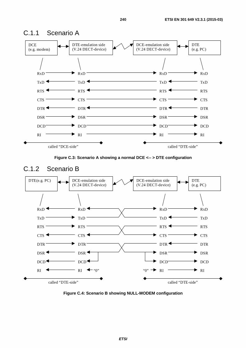
ETSI
ETSI EN 301 649 V2.3.1 (2015-03) 240
C.1.1 Scenario A
Figure C.3: Scenario A showing a normal DCE <-- > DTE configuration
C.1.2 Scenario B
Figure C.4: Scenario B showing NULL-MODEM configuration
DCE(e.g. modem)
DTE-emulation side(V.24 DECT-device)
DCE-emulation side(V.24 DECT-device)
DTE(e.g. PC)
RxD
TxD
RTS
CTS
RxD
TxD
RTS
CTS
RxD
TxD
RTS
CTS
RxD
TxD
RTS
CTS
DTR
DSR
DCD
RI
DTR
DSR
DCD
RI
DTR
DSR
DCD
RI
DTR
DSR
DCD
RI
called “DCE-side” called “DTE-side”
DTE(e.g. PC) DCE-emulation side(V.24 DECT-device)
DCE-emulation side(V.24 DECT-device)
DTE(e.g. PC)
RxD
TxD
RTS
CTS
RxD
TxD
RTS
CTS
RxD
TxD
RTS
CTS
RxD
TxD
RTS
CTS
DTR
DSR
DCD
RI
DTR
DSR
DCD
RI
DTR
DSR
DCD
RI
DTR
DSR
DCD
RI
called “DTE-side” called “DTE-side”
“0” “0”

ETSI
ETSI EN 301 649 V2.3.1 (2015-03) 241
C.2 Specific coding for mobility class 2
C.2.1 IWU-Attribute coding Devices implementing the Interworking Units described in this annex shall use the following IWU-Attribute coding.
Bit: 8 7 6 5 4 3 2 1 Octet: 0 << IWU-ATTRIBUTES >> 1 Length of Contents (L) 2 1 CodeStd Profile 3 1 Negotiation
indicator Profile subtype
4
0/1 Stop bits
Data bits
Parity
5
0/1 Data rate
5a
1 B F Baudrate mode
Flow Control
5b
0 Maximum SDU length (Most significant 7 bits)
6
1 Maximum SDU length (Least significant 7 bits)
6a
Figure C.5: IWU Attribute coding
CodeStd (octet 3):
Bits 7 6 Meaning 0 1 Profile defined code.
Profile (octet 3):
Bits 5 4 3 2 1 Meaning 0 0 0 0 1 DPRS: character oriented or bit oriented services.
Negotiation indicator (octet 4):
Bits 7 6 5 Meaning 0 0 0 Negotiation not possible. 0 1 0 Peer attribute negotiation. 1 0 0 Exchanged attribute negotiation. 1 1 0 Exchanged attribute negotiation and Peer attribute negotiation. All other values are reserved.
Profile sub-type (octet 4):
Bits 4 3 2 1 Meaning 0 0 0 0 V.24.
Stop bits coding (octet 5):
Bits 7 6 Meaning 0 0 Not specified. 0 1 1 bit. 1 0 1,5 bits. 1 1 2 bits.

ETSI
ETSI EN 301 649 V2.3.1 (2015-03) 242
Data bits/Parity coding (octet 5):
Bits 5 4 3 2 1 Meaning 0 0 x x x 5 bits. 0 1 x x x 6 bits. 1 0 x x x 7 bits. 1 1 x x x 8 bits. x x 0 0 0 Odd. x x 0 1 0 Even. x x 0 1 1 None. x x 1 0 0 Forced to 0. x x 1 0 1 Forced to 1. 1 1 1 1 1 Not specified. All other values reserved.
NOTE 1: In some implementations the values for the V.24 parameters Data bits and Parity are strongly related. For example, it is possible to support even or none Parity and 7 or 8 data bits, but not in all permutations. Normally you support 8 data bit with no parity and 7 data bits with even or odd parity. So you have always 8 Bit information.
Examples for Stop bits/Data bits/Parity coding:
Bits 7 6 5 4 3 2 1 Meaning 0 1 1 1 0 1 1 8N1. 0 1 1 0 0 1 0 7E1. 0 1 1 0 0 0 0 7O1.
Data rate (octet 5a):
Bits 7 6 5 4 3 2 1 Meaning 0 0 0 0 0 0 0 Not specified. 0 0 0 0 1 x x (x x+1) x 50 bit/s (50 bit/s to 200 bit/s.). 0 0 0 1 x x x (x x x+1) x 300 bit/s (300 bit/s to 2 400 bit/s.). 0 0 1 x x x x (x x x x+2) x 2 400 bit/s (4 800 bit/s to 40 800 bit/s.). 0 1 x x x x x (x x x x x+1) x 8 000 bit/s (8 000 bit/s to 256 000 bit/s) (see note 2). 1 0 x x x x x (x x x x x+6) x 9 600 bit/s (57 600 bit/s to 35 520 bit/s) (see note 2). 1 1 0 x x x x (x x x x+11) x 24 000 bit/s (264 000 bit/s to 624 000 bit/s) (see note 2). 1 1 1 0 0 0 0 75 bit/s. 1 1 1 0 0 0 1 110 bit/s. 1 1 1 0 0 1 0 134,5 bit/s. 1 1 1 0 0 1 1 75 bit/s to 1 200 bit/s (see note 3). 1 1 1 0 1 0 0 1 200 bit/s to 75 bit/s (see note 3). All other values reserved.
NOTE 2: Some bit rates (24 000 bit/s, 96 000 bit/s, 144 000 bit/s, 192 000 bit/s, 240 000 bit/s, 288 000 bit/s, and 336 000 bit/s) are codeable in several different ways. The different codings are all valid.
NOTE 3: The first rate is the transmit rate in forward direction of the call. The second rate is the transmit rate in backward direction of the call.
Examples for Data rate:
Bits 7 6 5 4 3 2 1 Meaning 0 0 0 0 1 0 0 50 bit/s. 0 0 0 0 1 0 1 100 bit/s. 0 0 0 0 1 1 0 150 bit/s. 0 0 0 0 1 1 1 200 bit/s. 0 0 0 1 0 0 0 300 bit/s. 0 0 0 1 0 0 1 600 bit/s. 0 0 0 1 0 1 1 1 200 bit/s. 0 0 0 1 1 1 1 2 400 bit/s. 0 0 1 0 0 0 0 4 800 bit/s. 0 1 0 0 0 0 0 8 000 bit/s. 0 0 1 0 0 1 0 9 600 bit/s.

ETSI
ETSI EN 301 649 V2.3.1 (2015-03) 243
0 0 1 0 0 1 1 12 000 bit/s. 0 0 1 0 1 0 0 14 400 bit/s. 0 1 0 0 0 0 1 16 000 bit/s. 0 0 1 0 1 1 0 19 200 bit/s. 0 0 1 1 0 0 0 24 000 bit/s. 0 0 1 1 0 1 0 28 800 bit/s. 0 1 0 0 0 1 1 32 000 bit/s. 0 0 1 1 1 1 0 38 400 bit/s. 0 1 0 0 1 0 1 48 000 bit/s. 0 1 0 0 1 1 0 56 000 bit/s. 1 0 0 0 0 0 0 57 600 bit/s. 0 1 0 0 1 1 1 64 000 bit/s. 1 0 0 0 0 0 1 67 200 bit/s. 1 0 0 0 0 1 0 76 800 bit/s. 0 1 0 1 0 0 0 72 000 bit/s. 0 1 0 1 0 1 1 96 000 bit/s. 1 0 0 0 1 1 0 115 200 bit/s. 0 1 0 1 1 1 0 120 000 bit/s. 0 1 0 1 1 1 1 128 000 bit/s. 1 0 0 1 0 0 1 144 000 bit/s. 1 1 0 1 0 1 0 552 000 bit/s.
B (bit 7 Octet 5b) 0 The value indicated in the "Baudrate mode" field shall be understood as request; the
responding side shall either accept it or return the default value otherwise. 1 The value indicated in the "Baudrate mode" field shall be understood as suggestion; the
responding side may respond with any value and the initiating side shall accept it.
F (bit 6 Octet 5b) 0 The value indicated in the "Flow control" field shall be understood as request; the responding
side shall either accept it or return the default value otherwise. 1 The value indicated in the "Flow control" field shall be understood as suggestion; the
responding side may respond with any value and the initiating side shall accept it.
Baudrate mode (octet 5b)
Bits 5 4 Meaning 0 0 Nodynamic detection. 0 1 Dynamic detection at FP. 1 0 Dynamic detection at PP. 1 1 Reserved.
Flow control (octet 5b)
Bits 3 2 1 Meaning 0 0 0 No Data Flow Control. x x 1 Hardware Data Flow Control (RTS/CTS). x 1 x Hardware Data Flow Control (DTR/DSR). 1 x x Software Data Flow Control (Xon/Xoff).
NOTE 4: It is not recommended to use a combination of flow controls.
Maximum SDU size (octets 6 and 6a): This 14-bit word represents the natural binary coding of the maximum SDU length in octets used for data transmission, with the least significant bit in position 1 of octet 6a.
C.2.2 Default-values It is necessary to have default-values for the V.24 parameters, which can be easily supported by all V.24-devices:
Stop bits: 1.
Data bits: 8.
Parity: N

ETSI
ETSI EN 301 649 V2.3.1 (2015-03) 244
Data rate: 19 200 bit/s.
Baudrate mode: no dynamic detection.
Flow control: no.
If dynamic data rate detection is supported the device shall support all data rates of the following list up to and including the negotiated data rate.
300, 600, 1 200, 2 400, 4 800, 9 600, 19 200, 38 400, 57 600, 115 200.
C.2.3 Negotiation of the V.24-parameters Each V.24 parameter is negotiated separately. The V.24 parameters shall be negotiated call-by-call.
If octets 6 and 6a need to be included at least Octet 5 shall be included as well and consequently values for < Stop bits >, < Data bits > and < Parity > shall be indicated, in this case octets 5a and 5b can still be omitted if the default values of the fields as indicated in clause C.2.2 are suggested. If octets 6 and 6a are omitted (the default value for the SDU max size implies as being suggested), octets 5, 5a and 5b can be omitted as well (all defaults values imply as being suggested).
For negotiation of V.24 parameters the following rules shall apply:
Stop Bits: The initiating side may suggest any valid value for this V.24 parameter. The receiving shall either accept the suggested value by returning the same value in the response or return the default value if the suggested value is not acceptable. The negotiated value shall be the value returned by the responding side (when complying with the rules above).
Data bits: Same as "Stop bits".
Parity: Same as "Stop bits".
Data rate: The initiating side may request any data rate. The receiving side shall either accept the suggested value by returning the same value in the response or return values lower than the suggested, or, the default value specified in clause C.2.2. The negotiated value shall be the value returned by the responding side (when complying with the rules above).
Baudrate mode: Same as "Stop bits".
Flow control: Same as "Stop bits".
NOTE: The aim of this negotiation is, to negotiate the highest common data rate of both sides as fast as possible. So the "algorithm" is optimized for this aim.
If the initiating side indicates for any value "Not specified" or the bits B and F are set, the responding side may return back any value.
If negotiation fails, to avoid endless attempt for negotiation new call setup should be initiated with default values.
C.3 Generic interworking conventions
C.3.1 PAD functionality This clause describes the Packet Assembly/Disassembly unit (PAD) functionality for interworking to character oriented (asynchronous) protocols.
C.3.1.1 Character formatting
Information is transferred between PAD entities using LU10 frames. The LU10 frame Service Data Unit (SDU) has variable length of 1 octet to 1 024 octets. The octets within the LU10 SDU are numbered 0 to n-1, octet 0 is transmitted first. The bits within the octets are numbered 1 to 8, bit 1 is transmitted first. The PAD functions as follows:

ETSI
ETSI EN 301 649 V2.3.1 (2015-03) 245
Characters are coded into octets in the following way:
• the first bit of the character received/transmitted over the upper PAD interface corresponds to bit position 1 in the octet. The second bit-to-bit 2, and the eighth bit-to-bit 8;
• 8 bit characters are transmitted with no padding. Where parity is used it is generated/removed locally;
• 7 bit characters are padded with a "0" in bit position 8. Where parity is used it is inserted in bit position 8;
• 6 bit characters are padded with a "0" in bit positions 7 and 8. Where parity is used it is inserted in bit position 7;
• 5 bit characters are padded with a "0" in bits positions 6, 7 and 8 if no parity is used. Where parity is used it is inserted in bit position 6;
• all start/stop bits are generated/removed locally by the application;
• the character configuration (length, start, stop and parity, etc.) information is conveyed between PAD entities in the {CC-SETUP} message in the << IWU-ATTRIBUTES >> information element during the call establishment phase;
• characters are inserted into the PAD-buffer in order of transmission in octets 0 to n-1.
C.3.2 Support of SDU size All implementations shall support a SDU size of at least the result of the following formula, which depends on the negotiated data rate and other V.24 parameters and shall be calculated at each side. A different value can be negotiated.
1) )1(8))_2()((
)(,29(SDU_size ++××
××+++×= − ffsetsecurity_ot
bitsstopsparity_bitdata_bits
sparity_bitdata_bitsdata_rateMAX frameTDMA
security_offset = 7 %
The result of this calculation shall be rounded up to the nearest integer.
A security offset is necessary because of jitter-effects on V.24-interfaces. The value for the security offset is a result of practical experiences.
Table C.1: Values for common data rates and V.24 parameters
Data rate Data bits/Parity/Stop bits Max. supported SDU size 1 200 8N1, 7E1, 7O1 29 2 400 8N1, 7E1, 7O1 29 4 800 8N1, 7E1, 7O1 29 9 600 8N1, 7E1, 7O1 29
19 200 8N1, 7E1, 7O1 29 38 400 8N1, 7E1, 7O1 43 57 600 8N1, 7E1, 7O1 63
115 200 8N1, 7E1, 7O1 125
C.3.3 LU10 SDU delivery mode The SDU in-sequence delivery mode (see ETSI EN 300 175-4 [4], clause 11.12.3.2.2) shall be used.
C.4 V.24 circuits
C.4.1 General The V.24 interworking supports the V.24 circuits as given in table C.2. This table also relates the official Recommendation ITU-T V.24 [18] circuit names to the more practical names as used in DPRS.

ETSI
ETSI EN 301 649 V2.3.1 (2015-03) 246
Table C.2: IWU V.24 support
V.24 Circuit V.24 Meaning DPRS name Direction 103 Transmitted data TXD (Transmit Data) To DCE 104 Received data RXD (Receive Data) From DCE 105 Request to send RTS (Request To Send) To DCE 106 Ready for sending CTS (Clear To Send) From DCE 107 Data set ready DSR (Data Set Ready) From DCE
108/2 Data terminal ready DTR (Data Terminal Ready) To DCE 109 Data channel received line signal detector DCD (Data Carrier Detect) From DCE 125 Calling indicator RI (Ring Indicator) From DCE
Additional functionalities are:
• Xon, Xoff;
• Break and Pause.
NOTE: Indication of break and pause conditions are not foreseen as they are not required for proper operation in nearly all cases.
If supported, the break and pause conditions shall be optional and therefore be transmitted within an optional user control information element as described above.
The V.24 connection establishment shall not influence DECT call control. The call control is only necessary to establish the connection and configure the serial port such as data coding, data rate, etc.
All information (signalling- and user data) of the V.24 connection is transferred via an encapsulation protocol.
C.4.2 Encapsulation
C.4.2.1 Description
For transmission a one-octet header is inserted to multiplex signal-, control-or user data on the same DECT-data link.
C.4.2.2 Framing
The framing format is defined as below.
First octet Following octets Header Data
Figure C.6: Framing of encapsulation
C.4.2.3 Coding of encapsulation
Bit: 8 7 6 5 4 3 2 1 E DCD RI DTR/DSR RTS/CTS Reserved Reserved Reserved
Figure C.7: Header of encapsulation
The DTR/DSR or RTS/CTS bit respectively indicates that the peer side is not able to receive further data and therefore allows end-to-end flow control (depends on the negotiated type of Dataflow-control). It may be set with respect to the real status of the line and/or by the implementation e.g. due to the buffer status respectively.
NOTE: On the DCE-emulation side is no incoming DCD- or RI-signal from the DTE-device. Therefore the following default values should be set: RI = 0. DCD = DSR. With these values a proper DCE/DCE-connection (nullmodem) can be guaranteed.
The two bits DTR/DSR and RTS/CTS in the Headerbyte are ambiguous. Therefore we need a rule how the Header shall be interpreted exactly.

ETSI
ETSI EN 301 649 V2.3.1 (2015-03) 247
C.4.2.3.1 DCE-emulation side interpretation
The DCE-emulation side (connected to a DTE) shall interpret received header-bits as follows:
DCD: DCD.
RI: RI.
DTR/DSR: DSR.
RTS/CTS: CTS.
C.4.2.3.2 DTE-emulation side interpretation
The DTE-emulation side (connected to a DCE) shall interpret the header-bits as follows:
DCD: Ignored.
RI: Ignored.
DTR/DSR: DTR.
RTS/CTS: RTS.
C.4.2.4 SDU Structure
User Control Data (E-Bit = 1) SDU - Header
E Generic User Control Status Information
SDU - Contents
User Control Data (if E-Bit = 1)
User Control Data (E-Bit = 1)
User Data
User Information Element Identifier 1 Octet 1
Length of Contents Octet 2
...
For a list of mandatory and optional
UIEs see C.5.x
8 7 6 5 4 3 2 1
Contents
User Information Element Identifier n
Length of Contents
Contents
Octet 3
Length of User Control Data Octet 0
Octet (n-1) × 3 + 1
Octet (n-1) × 3 + 2
Octet (n-1) × 3 + 3
Figure C.8: Extended field (data) of encapsulation
The user data is transmitted transparent, but stop and start bits shall not be assembled. These bits shall be generated locally by the application. For 8 bit characters with an additional parity bit, the parity bit shall also be generated locally.
By resetting the extended bit (E = 0), the entire SDU-Contents are equal to the user data.

ETSI
ETSI EN 301 649 V2.3.1 (2015-03) 248
If the extended bit is set, both user control and user data may be inserted into the extended information field.
The first byte identifies length of directly following user control data. This byte is applied to reroute the user control and user data into the corresponding SAPs (see figure C.2).
C.4.3 Interworking procedures and conventions
C.4.3.1 General
C.4.3.1.1 Data forwarding conditions
User data and signalling data shall be assembled until one or more of the following conditions are met:
• a timer expires at any time;
• the SDU is forwarded to U-plane service entity.
C.4.3.1.2 Dataflow Control
The dataflow shall take action local but shall be overlayed by Path-By Path or End-2-End Flow Control. Exception: It is not allowed to overlay an active local flow control with an inactive Path-By-Path or End-2-End flow control. The control information shall be generated by U-plane service or set over V.24 interface.
C.4.3.1.2.1 Software dataflow control
If the IWU notifies that the U-plane service is not ready to transfer data, it shall generate an Xoff. If the U-plane service indicates the data should be transmitted once again the IWU shall generate an Xon.
If the IWU notifies that an Xoff is received by V.24 interface, the IWU shall stop to transmit data over V.24 interface.
If the Xon identify is received at V.24 interface the IWU start to transmit once again.
C.4.3.1.2.2 Hardware dataflow control
The flow control condition indication shall be performed using circuits RTS/CTS or circuits DTR/DSR, in these cases:
At DCE-emulation side IWU interface (connected to a DTE):
• a DCE-emulation side IWU not-ready condition, initiated U-plane service, shall be indicated by turning circuit 106 (CTS) or 107 (DSR) OFF and cleared by turning circuit 106(CTS) or 107(DSR) ON;
• a DTE not ready condition shall be recognized by an ON-OFF transition and cleared by an OFF-ON transition of circuit 105 (RTS) or 108 (DTR).
At DTE-emulation side IWU interface (connected to a DCE):
• a DTE-emulation side IWU not-ready condition, initiated U-plane service, shall be indicated by turning circuit 105 (RTS) or 108 (DTR) OFF and cleared by turning circuit 105 (RTS) or 108 (DTR) ON;
• a DCE not ready condition shall be recognized by an ON-OFF transition and cleared by an OFF-ON transition of circuit 106(CTS) or 107(DSR).
NOTE: On running system, either DTR/DSR or RTS/CTS mode is available. This is set in the IWU-Attribute.
C.4.3.1.3 Transmission of U-plane data procedure
If the SDU is forwarded to U-plane service entity, the actual line states of V.24 are inserted into the header (done by the application).
C.4.3.1.4 Receive of U-plane data procedure
The header is to compare if line states of V.24 connection have been changed.

ETSI
ETSI EN 301 649 V2.3.1 (2015-03) 249
C.4.3.1.5 V.24 signalling
The circuits 106 (CTS)/105 (RTS) or 107 (DSR)/108 (DTR) shall be generated locally and maybe overlayed by Path-By-Path or End-2-End flow control.
C.4.3.1.6 Configuration a V.24 interface during a Connection
The initiating side:
The IWU shall stop the user data transmission by using the dataflow control, it sends also the remaining data into transmit buffers and shall issue MNCC _MODIFY.req, specifying the configuration of serial interface and link, and shall await a MNCC _MODIFY.cfm primitive. If this primitive notifies failure, it shall enter the release-procedure, otherwise the dataflow control enable the data flow.
The destination side:
If the IWU receives a MNCC _MODIFY.ind, it shall stop the data transmission by using the dataflow control, afterwards the buffer shall be cleared, the serial port shall be configure and shall await incoming data of the initiating side.
NOTE: It is not necessary in all MNCC_MODIFY-events to stop the data transmission, etc. (for example: bandwidth-modification).
C.4.3.2 Fall back procedure
If the DECT-Link breaks off, the DCE-emulation side IWU shall clear the buffer and turn circuit 107 (DSR)/106 (CTS), circuit 125 (RI) and circuit 109 (DCD) off, the DTE-emulation side IWU shall clear the buffer and turn circuit 108 (DTR) and circuit 105 (RTS) off.
C.4.3.3 Procedure at the DCE-emulation side IWU
The IWU shall emulate a DCE. Received Data (from the air-interface) shall be forwarded via the circuit RxD to the DTE and V.24 data shall be received via the circuit TxD from the DTE (see figure C.3 for details).
NOTE: The dataflow control is not special notified. It is defined in clause C.4.3.1.2.
C.4.3.3.1 DTE-initiated VC establishment
If no V.24 call is established, then the IWU shall monitor the value of all state-lines. If DTR line goes ON, the IWU shall monitor the activity of the circuit TxD. The circuit TxD shall also be monitored, if no dataflow mode is negotiated. If data is detected on the circuit TxD line or a state on the state-lines is changed, then the IWU shall issue a MNCC_SETUP-req primitive and change the state to "V.24 call Requested".
In the "V.24 call Requested" state, if the IWU receives a MNCC_REJECT-ind primitive, it shall clear the buffer and set DSR-, CTS-, RI- and DCD-line OFF and shall return to the "No V.24 call" state. Its subsequent action shall be locally determined on the basis of the release reason contained in the primitive.
In the "V.24 call Requested" state, if the IWU receives a MNCC_CONNECT-ind primitive it shall enter a "V.24 call Active" state. Other primitives might be received before MNCC_CONNECT.
C.4.3.3.2 DCE-initiated VC establishment
Upon the receipt of a MNCC_SETUP-ind primitive, the IWU shall determine that the service requested may be offered, and if so it will issue a MNCC_CONNECT-ind primitive and enter the "V.24 call Active" state. Other primitives might be sent before MNCC_CONNECT.
If the service cannot be supported, it will issue a MNCC_REJECT-req, indicating a release reason, and will return to the "No V.24 call" state.
C.4.3.3.3 V.24 call release
The application shall decide in which cases the V.24 call should be released. The V.24 call release shall be done using the NWK Call release procedure (see GAP).

ETSI
ETSI EN 301 649 V2.3.1 (2015-03) 250
C.4.3.4 Procedure at the DTE-emulation side IWU
The IWU shall emulate a DTE. Received data (from the air-interface) shall be forwarded via the circuit TxD to the DCE and V.24 data shall be received via the circuit RxD from the DCE (see figure C.3 for details).
C.4.3.4.1 DCE-initiated VC establishment
If no V.24 call is established, then the IWU shall monitor the value of all state-lines. If the DSR line goes ON, then the IWU shall monitor the activity of the circuit RxD. The circuit RxD shall also be monitored, if no dataflow mode is negotiated. If data is then detected on the circuit RxD line, or any state line is changed, then the IWU shall issue a MNCC_SETUP-req primitive and shall enter the "V.24 Call Requested" state.
In this state, if the IWU receives a MNCC_REJECT-ind primitive, it shall clear the buffer and shall return to the "No V.24 Call" state. Its subsequent action shall be locally determined on the basis of the release reason contained in the primitive.
In the "V.24 Call Requested" state, if the IWU receives a MNCC_CONNECT-ind primitive it shall enter a "V.24 Call Active" state. Other primitives might be received before MNCC_CONNECT.
C.4.3.4.2 DTE-initiated VC establishment
Upon the receipt of a MNCC_SETUP-ind primitive, the IWU shall determine that the service requested may be offered, and if so it will issue a MNCC_CONNECT-ind primitive and enter the "V.24 Call Active" state. Other primitives might be sent before MNCC_CONNECT.
Once in this state, it shall set the value of the DTR line to the value communicated to it by U-plane service. If the service cannot be supported, it will issue a MNCC_REJECT-req, indicating a release reason, and will return to the "No V.24 Call" state.
C.4.3.4.3 V.24 call release
The application shall decide in which cases the V.24 Call should be released. The V.24 call release shall be done using the NWK Call release procedure (see ETSI EN 300 444 [11]).
C.5 Definition of User Control Information Elements UIEs can be sent within each SDU. It is allowed to send user data and UIEs in one SDU (see clause C.4.2.4).
C.5.1 Mandatory UIEs No mandatory UIEs at this time.
C.5.2 Optional UIEs A device can send the UIE < release_reason > at any time. If a device receives this UIE it can decide how to react.
UIE_RELEASE_REASON:
Field Code Comment Tag UIE_RELEASE_REASON Release Reason Length 1 1 byte following Value Bits 8 7 6 5 4 3 2 1
0 x x x x x x x 1 0 0 0 0 0 0 0 All other values reserved.
Proprietary reasons Reason not known
Some operating systems (e.g. Unix) sometimes use a special behaviour of the start- and stop-bit. To support this behaviour, the following two UIEs are necessary.
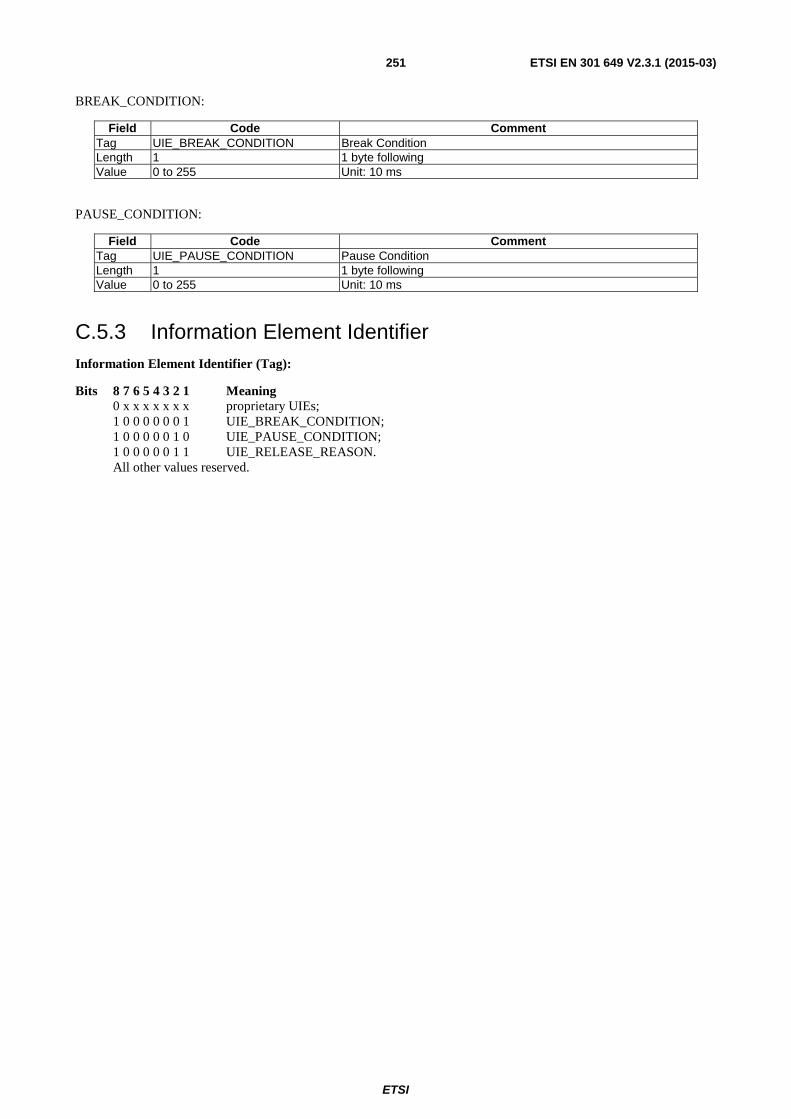
ETSI
ETSI EN 301 649 V2.3.1 (2015-03) 251
BREAK_CONDITION:
Field Code Comment Tag UIE_BREAK_CONDITION Break Condition Length 1 1 byte following Value 0 to 255 Unit: 10 ms
PAUSE_CONDITION:
Field Code Comment Tag UIE_PAUSE_CONDITION Pause Condition Length 1 1 byte following Value 0 to 255 Unit: 10 ms
C.5.3 Information Element Identifier Information Element Identifier (Tag):
Bits 8 7 6 5 4 3 2 1 Meaning 0 x x x x x x x proprietary UIEs; 1 0 0 0 0 0 0 1 UIE_BREAK_CONDITION; 1 0 0 0 0 0 1 0 UIE_PAUSE_CONDITION; 1 0 0 0 0 0 1 1 UIE_RELEASE_REASON. All other values reserved.

ETSI
ETSI EN 301 649 V2.3.1 (2015-03) 252
Annex D (normative): Support of double and long slot
D.1 Double and long slot support (2-level modulation)
D.1.1 General DPRS supports long slot 640, long slot 672 and double slots.
All DPRS procedures can be used with full, long 640, long 672 and double slots.
The main text of DPRS was initially written assuming that full slot is the slot type in use. This annex adds specific requirements applicable when the other slot types are used.
For systems using long 640, long 672 or double slot types, the requirements specified in the following clauses shall apply.
D.1.2 Requirements
D.1.2.1 Frame structure and slot numbering
For the frame structure and slot numbering in the case of double slot utilization see ETSI EN 300 175-3 [3], clause 4.2.2. Long slots are equivalent to double for this purpose.
Long and double slots may start at both, even and odd full slot intervals. However Management Entity algorithms shall favour the start in even positions.
In absence of other constrains (interference and slot availability), the slots should start at even positions.
D.1.2.2 Multibearer connections
All bearers of a multibearer connection shall be from the same slot type, i.e. either full, long 640, long 672 or double slot, as specified in ETSI EN 300 175-3 [3], clause 5.6.2. It is not allowed to have bearers of different type as part of one connection.
NOTE: However, a different slot size may be simultaneously used for other services (i.e. voice).
D.1.2.3 Modulation schemes
No changes.
D.1.2.4 Void
D.1.2.5 Bit MAPs
The D-field and B-field mappings for the used slot type are applicable, as indicated in the MAC feature to procedure table.
D.1.2.6 C-MUX
No changes. The rules regarding long and double slots as specified in ETSI EN 300 175-3 [3], clause 6.2.2.3.1 apply.
D.1.2.7 Scrambling
The rules as specified in ETSI EN 300 175-3 [3], clause 6.2.4 regarding long and double slots apply.
D.1.2.8 CRC
The rules as specified in ETSI EN 300 175-3 [3], clause 6.2.5 regarding long and double slots apply.

ETSI
ETSI EN 301 649 V2.3.1 (2015-03) 253
NOTE: The CRC generation schema for double slots is different to the one for long and full slots.
D.1.2.9 B-field type identification
• "010" - double slot required.
• "101" long slot 640 required.
• "110" long slot 672 required.
Shall be used as specified in ETSI EN 300 175-3 [3], clause 7.1.4.
D.1.2.10 Fixed Part capabilities
FT that supports double and/or long slots shall indicate this in the Qt3 message setting bit a15 to 1 as specified in
ETSI EN 300 175-3 [3], clause 7.2.3.4. Support of long slot 640 and long slot 672 is indicated by bits a12 and a13 of
"Extended Physical and MAC layer capabilities (part 2)" as specified in ETSI EN 300 175-3 [3], clause 7.2.3.11.2.
D.1.2.11 Portable Part capabilities
PT shall indicate whether it supports double and/or long slot operation in << Terminal Capability >> information element by setting the <Slot type capability> field to indicate in addition to the "full slot", "double slot" as well = 011, as specified in ETSI EN 300 175-5 [5], clause 7.7.41.
D.1.2.12 Blind slot information
Blind slot information for double slots shall be provided in the PT message where bits a32 to a35 in the PT message
header shall be set to 1110, as specified in ETSI EN 300 175-3 [3], clause 7.2.4.3.1, and the relevant information shall be provided according to ETSI EN 300 175-3 [3], clause 7.2.4.3.11.
Blind slot indication for long slots has its specific broadcast.
D.1.2.13 Advanced connection control
The field "slot type" where available shall be set to the intended slot type "double slot" "long 640", "long 672" or "full slot" of the corresponding connection, e.g. see ETSI EN 300 175-3 [3], clause 7.3.2.5 for the coding of ATTRIBUTES_B message or clause 7.2.5.2.4 for the coding of ATTRIBUTES_T. "Double slot", "long 640" or "long 672" shall be indicated wherever necessary in the primitives exchanged between DLC and MAC layer as specified in ETSI EN 300 175-4 [4], clause 10.2.3.
D.1.2.14 CF channel
If CF channel is supported for double slot or long slot connections the rules as specified in ETSI EN 300 175-3 [3],
clause 10.8.1.2 shall apply.
D.1.2.15 Call establishment
For FT initiated DPRS virtual call setup, the FT shall page the PT with Full Page format indicating the required slot type. All bearers of the connection shall use the same slot type.
D.1.2.16 Slot type modification during a call
Slot type modification after a virtual call has been established may optionally be supported. If implemented, the procedure shall be performed as follows:
1) There should not be any PDU pending for transmission or possible retransmission at DLC layer.
NOTE 1: The second part of the requirement means that the Tx should wait either for the reception of an ACK command advancing the window, or for the expiration of the maximum lifetime timer. See DLC LU10 service operation.
2) Bandwidth shall be set to single-bearer and the bandwidth change (if needed) shall be completed.

ETSI
ETSI EN 301 649 V2.3.1 (2015-03) 254
NOTE 2: Step 2 may be a bandwidth reduction or a resume if the connection was suspended.
NOTE 3: Steps 1 and 2 may be done in any order.
3) The MAC connection type modification changing the slot type procedure as specified in ETSI EN 300 175-3 [3], clause 10.3.3 shall be performed using B-field signalling and without transmitting any U-plane data.
During stage 3, the DLC will not accept any SDU from higher layers.
Once stage 3 is completed, the DLC may accept new SDUs that shall be split in PDUs according to the size of the new slot type.
If connection type modification procedure fails without release (see ETSI EN 300 175-3 [3], clause 10.3.3) the virtual call shall not be released and will continue with the existing slot type.

ETSI
ETSI EN 301 649 V2.3.1 (2015-03) 255
Annex E (informative): Implementation guidelines and examples
E.1 Scope of this annex This annex gives some flowcharts for typical use cases of DPRS data calls with multibearer and complete C-plane (Class 2). The first part of the annex includes flowcharts for, virtual call setup (several cases), virtual call release, service change, MAC suspend, MAC resume, MAC bandwidth change and C-plane only operations (Access-Right request, NWK layer C-plane example and stay-alive, MAC layer C-plane only example).
The second part of the annex (clause E.3) shows an example of operation for a typical HTTP data transfer.
The third part of the annex clause E.4) introduced a few examples of detailed diagrams with the optimal timing for selected operations (timed diagrams).
The fourth part (clause E.5) introduces some examples regarding the DPRS Generic Encapsulation Interworking.
Please note that they are simple and convenient implementation examples that may considered as good practice cases. However they may not be considered as the only possible implementation of the current standard (some variations are allowed). The clauses of the annex containing flowcharts can be divided into atomic groups to allow for various implementations:
• [DPRS-CAT.1] mandatory features (single bearer connection): clauses E.2.1, E.2.2, E.2.3 and E.2.6.
• symmetric multibearer connections: previous ones + clause E.2.4.
• asymmetric connections: previous ones + clauses E.2.5 (bandwidth expansion, asymmetric downlink), E.2.6 (bandwidth expansion asymmetric uplink) and E.2.8 (bandwidth reversal with fast release).
• Virtual call release: clause E.2.9.
• Bandwidth change: clause E.2.7 (PT initiated).
• suspend, resume, fast-setup: any of the above + clauses E.2.10 (FT suspend), E.2.11 (PT suspend), E.2.12 (PT resume), E.2.13 (FT resume via fast setup), E.2.14 (FT resume via paging) and E.2.15 (resume rejected by FT).
• stay alive: clause E.2.16, service re-negotiation at NWK layer: clause E.2.17.
The following notation conventions are adopted:

ETSI
ETSI EN 301 649 V2.3.1 (2015-03) 256
For MAC procedures the following notation is used: A(message 1) B0(message 2) B1(message 3), etc.
• A(message 1) stands for "message 1 sent in the A field".
• B0(message 2) stands for "message 2 sent in the first subfield (i.e. B0) of the multiple subfield B field format".
E.2 Flowcharts
E.2.1 Declaration of capabilities during subscription or location registration procedures
This use case is depicted in figure E.1.
Figure E.1: Declaration of capabilities during subscription or location registration procedures
NOTE 1: Declaration of PP capabilities may also be done during location registration procedure.
NOTE 2: "On air key allocation" feature is optional for FT, but it is recommended to perform it in order to use a dynamic key (i.e. User Authentication Key) for "Authentication of PP" feature which is mandatory.
FT-NWK FT-DLC FT-MAC PT-MAC PT-DLC PT-NWK
QH=3 (Extended FP info, double slot [0,1], B-field setup, CF [0,1], Ip_error_detection, Ip_error_correction [0,1] / Multibearer connections [0,1], Non-voice circuit)
ACCESS_RIGHTS_REQUEST <<Terminal capability = Asymmetric bearers [0,1], DPRS FREL, Ethernet, IP [0,1], CF [0,1], IPQ [0,1], E+U Mux and IPF basic [0,1], NG-DECT Packet Data Category [0,1,2,3], GF [0,1]>>
ACCESS_RIGHTS_ACCEPT
FP capabilities / Higher layer capabilities
QH=4 (MAC suspend and resume, IPQ [0,1], Extended FP capabilities part 2 / Ethernet, IP [0,1], Asymmetric bearers [0,1], DPRS FREL)
Extended FP capabilities / Extended Higher layer capabilities
QH=C (Long slot (640), E+U mux and IPF basic [0,1], GF [0,1] / NG-DECT Packet Data Category [0,1,2,3])
Extended FP capabilities part 2 / Extended Higher layer capabilities part 2
KEY_ALLOCATE
AUTHENTICATION_REPLY
AUTHENTICATION REQUEST
PT initiated pilot bearer setup procedure (see flowchart E.2.2)
PP AND FP ARE READY TO INITIATE A VIRTUAL CALL (POSSIBLE IN EACH DIRECTION)

ETSI
ETSI EN 301 649 V2.3.1 (2015-03) 257
E.2.2 Virtual call opening, first phase: establishment of the pilot bearer (valid for all DECT data system categories)
This use case is depicted in figure E.2.
Figure E.2: Virtual call opening, first phase: establishment of the pilot bearer (valid for all DECT data system categories)
NOTE 1: Virtual call is initiated either from the PP or from the FP. In the last case, the LCE-REQUEST-PAGE message with LCE code =110 is used.
NOTE 2: A virtual call always begins with the setup of an initial duplex bearer (also called pilot bearer). For this setup the B-field single bearer setup procedure (see ETSI EN 300 175-3 [3], clause 10.5.1.3) should be used (see clause 10.10.1.2). The setup messages (bearer request, bearer confirm, other, other) should always be sent in the physical channel selected for the new bearer.
NOTE 3: PT initiated bearer request has the following characteristics:
� TA (Tail identification) code = 111 (meaning "MT first PP transmission").
� BA bits with the slot type.
� A-tail with MT message "B-field setup" (defined in ETSI EN 300 175-3 [3], clause 7.2.5.8).
� BEARER_REQUEST in B0.
� It may carry other messages in other subfields (Bn).
NOTE 4: Some WAIT messages may be sent from peer side between bearer request and confirm messages (see clause 10.5.1.1 of ETSI EN 300 175-3 [3] and clause 10.10.1.2.3 of the present document), but the use of WAIT messages should be avoided.
NOTE 5: "other" messages are used after the "bearer confirm" message in order to test the usability of the newly setup bearer. Correct reception of the "other" message enables the bearer state to be switched to "Bearer_Established" on the receiving side and is therefore a condition for successful termination of the procedure. The "other" messages may be any message (except release), i.e. any A-field (including NT) or
B-field (see ETSI EN 300 175-3 [3], clause 10.5.1.3).
DL_ESTABLISH-req MAC_CON-req
A(B-field setup) B0(BEARER_REQUEST)
B0(BEARER_CONFI
OTHER OTHER
MAC_CON-ind DL_ESTABLISH-ind
MAC_CON-cfm DL_ESTABLISH-cfm
LCE-REQUEST-PAGE <LCE = 110>
FT-NWK FT-DLC FT-MAC PT-MAC PT-DLC PT-NWK
virtual call PT initiated
virtual call FT initiated
SEE FOLLOWING FLOWCHARTS ACCORDING TO WANTED CATEGORY
PILOT BEARER IS ESTABLISHED

ETSI
ETSI EN 301 649 V2.3.1 (2015-03) 258
NOTE 6: After pilot bearer setup, there are 3 possibilities: 1/ keep the bandwidth as it is (use the bandwidth provided by the pilot bearer, see flowchart of clause E.2.3); 2/ increase the bandwidth (see flowchart of clauses E.2.4 and E.2.5); or 3/ suspend the virtual call by setting the bandwidth to zero, waiting for actual data to be transmitted (see flowcharts of clauses E.2.7 and E.2.8).
E.2.3 Virtual call establishment, second phase, use case 1: keeping the bandwidth as it is (single bearer connection)
This use case is depicted in figure E.3.
Figure E.3: Virtual call establishment, second phase, use case 1: keeping the bandwidth as it is (single bearer connection)
NOTE 1: A single bearer connection is a connection for which negotiated values for <Maximum number of bearers> and <Minimum number of bearers> are both equal to 1 (see flowchart of clause E.2.4, note 1 for negotiation constraints).
NOTE 2: "Mup, Mdown, Tup, Tdown" stands for "Minimum uplink, downlink, Maximum uplink, downlink number of bearers" (see ETSI EN 300 175-3 [3], clause 7.2.5.3.9).
NOTE 3: IP_error_detection MAC service is used in both directions.
NOTE 4: This use case is the typical Cat 1 case, but it can occur also for Cat 2 and Cat 3 devices.
NOTE 5: In <<Call attributes>> I.E. the flag "DPRS" is used for the <NWK layer attributes> field. This makes the call a packet virtual call.
NOTE 6: On each side, when the MAC layer receives MAC-MOD-req, the MBC (Multi-Bearer Control) behaviour changes. By default, the MBC has a circuit-mode behaviour, meaning in particular that the connection and the (pilot and only) bearer have the same lifecycle. On the contrary, in DPRS, bearers can disappear (cf. suspend/resume) while the connection at NWK layer remains active.
NOTE 7: MAC-MOD-cfm should not be issued until the connection is fully established.
FT-NWK FT-DLC FT-MAC PT-MAC PT-DLC PT-NWK
Establishing a single bearer symmetric virtual call 1+1 (no extra bearer to establish)
CC-SETUP <<IWU-attributes= FREL, Ethernet or IP>> <<Call attributes= DPRS+Symmetric>> <<Connection attributes= Maximum bearers (1,1), IP_error_detection >>
CC-CONNECT <<IWU-attributes= FREL, Ethernet or IP>> <<Call attributes= DPRS+Symmetric>> <<Connection attributes : Maximum bearers (1,1), IP_error_detection>>
DL_SERVICE_MOD-req (Mup=1, Mdown=1, Tup=1, Tdown =1)
MAC_MOD-req
MAC_MOD-req
DL_SERVICE_MOD-req
MAC_MOD-cfm DL_SERVICE_MOD-cfm
MAC_MOD-cfm DL_SERVICE_MOD-cfm
VIRTUAL CALL IS FULLY ESTABLISHED (51.2 kbit/s net data rate in each direction) Possible messages exchange for ciphering purposes (see. EN 300 175 7)
AUTHENTICATION_REQUEST
AUTHENTICATION_REPLY
CIPHER_REQUEST

ETSI
ETSI EN 301 649 V2.3.1 (2015-03) 259
E.2.4 Virtual call establishment, second phase, use case 2: increasing the bandwidth (Symmetric case)
This use case is depicted in figure E.4.
Figure E.4: Virtual call establishment, second phase, use case 2: increasing the bandwidth (Symmetric case)
NOTE 1: < Maximum number of bearers > and < Minimum number of bearers > are negotiated at network level for the whole call duration (thanks to the << Connection Attributes >> information element). If sent by the call originating side (i.e. in {CC-SETUP}), these values represent the requested number of bearers and the minimum acceptable number of bearers respectively.
� If the call originating side is the PT (as in the example), <Maximum number of bearers> in the response (i.e. in {CC-CONNECT}) represents the allocated number of bearers, and can be anywhere in between.
� If the call originating side is the FT, <Maximum number of bearers> in the response should be equal to <Maximum number of bearers> in the request, unless the requested value is out of PT implementation range: in such a case, the PT should answer with the maximum possible values.
The values coded in the response (if accepted) will be the minimum and maximum number of bearers for the whole call duration (unless a {SERVICE-CHANGE} is used, see flowchart of clause E.2.11). See clause 12.5 for <<IWU attributes>>, <<Call attributes>>, and <<Connection attributes>> details.
NOTE 2: In case of call setup, MAC-level bandwidth negotiation procedure should be initiated by the call originating side (see clause 10.7.1.1).
DL_SERVICE_MOD-req(Mup=n, Mdown=n, Tup=n, Tdown =n)
To be done (n-1) times (for each extra duplex bearer)
MAC_MOD-req
B0(BEARER_REQUEST) B0(BEARER_CONFIRM)
MAC_MOD-cfm
DL_SERVICE_MOD-cfm MAC_MOD-cfm
DL_SERVICE_MOD-cfm
B0(BANDWIDTH_B-req (n,n)) B0(BANDWIDTH_B-cfm (n,n) with optionally B1(LISTEN(slot nb, carrier nb))
CC-SETUP <<IWU-attributes= FREL, Ethernet or IP >> <<Call attributes= DPRS+Symmetric>> <<Connection attributes= Maximum bearers (n,n), IP_error_detection >>
CC-CONNECT <<IWU-attributes= FREL, Ethernet or IP>> <<Call attributes= DPRS+Symmetric>> <<Connection attributes= Maximum bearers (n,n), IP_error_detection>>
MAC_MOD-req
DL_SERVICE_MOD-req
OTHER OTHER
FT-NWK FT-DLC FT-MAC PT-MAC PT-DLC PT-NWK
VIRTUAL CALL IS FULLY ESTABLISHED (n * 51.2 kbit/s net data rate in each direction).
Establishing a Cat x symmetric virtual call n+n (n-1 duplex extra bearers to establish)
SEE FLOWCHARTS IN CLAUSES E.2.7 AND E.2.8 FOR SUSPEND/RESUME or SESSION RELEASE FLOWCHART IN CLAUSE E.2.6
AUTHENTICATION_REQUEST
AUTHENTICATION_REPLY
CIPHER_REQUEST
Optional (see note 7) Bx (LISTEN 1(slot nb, carrier nb),2,3)

ETSI
ETSI EN 301 649 V2.3.1 (2015-03) 260
NOTE 3: For all subclauses of clause E.2 flowcharts and in order to simplify exposition, the number of bearers in the "bandwidth confirm" message is assumed to be equal to the number of bearers in the "bandwidth request" message.
NOTE 4: In order to possibly improve efficiency of bandwidth usage, BANDWITH_B_REQ can be replaced with BANDWITH_T_REQ in A field (see clause 10.7.1.1). BANDWITH_B_REQ/CONFIRM negotiation of wanted bearers may be repeated if the first one fails.
NOTE 5: For symmetric connections, extra (or "additional") bearer setups should be PT initiated (see clause 10.2.4.3.1 of ETSI EN 300 175-3 [3] and clause 10.10.1.4.1 of the present document). The setup messages (bearer request, bearer confirm, other, other) for duplex bearers (initial or additional) is always sent in the physical channel selected for the new bearer. "other" messages may be used to send data information.
NOTE 6: For the setup of extra duplex bearers, it is highly recommended to use the channel list procedures. The term "channel" refers here to a TDD pair (i.e. two time slots using the same frequency; the starting points of the time slots being separated by 0,5 frame):
� The setup is always PT-initiated (this use case), the recommended channel list message is LISTEN (see clause 10.10.1.4.3) sent by the FT on an already established duplex bearer.
GOOD or POOR may sent by PT (at any time before the LISTEN), and depending on the case, being taken into account by the FT in the channel selection (see clause 10.10.1.5.3) Use of channel list procedures decreases the connection establishment time (see ETSI EN 300 175-3 [3], clause 10.2.4.3.1). Indeed, updates of the channel selection list and of the blind slot information are not done in real time on PP side; furthermore, the FP has a better view of the channels used (however, a free channel for this FP could be already in use by another FP, so the channel list procedure should be used in compliance with the channel selection rules defined in ETSI EN 300 175-3 [3], clause 11.4).
NOTE 7: The use of LISTEN for duplex is in practice quasi-mandatory. If no LISTEN command is sent, the PT cannot start until the expiration of a timer (10 frames).
NOTE 8: The fastest implementation possible is achieved by sending the LISTEN (duplex) commands in the same frame as the bandwidth FT ⇒ PT command. PT channel list info (GOOD/POOR) could be send with the bandwidth PT ⇒ FT command. See example in clause E.4.
E.2.5 Virtual call establishment, second phase, use case 3: increasing the bandwidth (Asymmetric downlink case)
Asymmetric downlink case (m+n) with m>n: establishing extra duplex and double simplex bearers. This use case is depicted in figure E.5.

ETSI
ETSI EN 301 649 V2.3.1 (2015-03) 261
Figure E.5: Virtual call establishment, second phase, use case 3: increasing the bandwidth (Asymmetric downlink case)
NOTE 1: (m+n) stands for m (simplex) bearers in FP ⇒ PP direction, and n (simplex) bearers in PP ⇒ FP direction.
NOTE 2: An asymmetric connection is a connection that has double simplex bearers. An asymmetric downlink (resp. uplink) connection is a connection for which all double simplex bearers are in the direction FP to PP (resp. PP to FP); in such a connection, FT (resp. PT) is the T-side (i.e. the transmitter of the double simplex bearers) and PT (resp. FT) is the R-side (i.e. the receiver of the double simplex bearers). For an asymmetric connection (uplink or downlink), extra duplex bearers and double simplex bearer setups are T-side initiated (see ETSI EN 300 175-3 [3], clauses 10.2.4.3.2, 10.2.4.3.3, and 10.5.1.4). For determining the T-side, the targeted connection type is used, not the current one. For determining the targeted connection type (asymmetric, uplink or downlink) the parameters TUp and TDown in the bandwidth message FT ⇒ PT (request or confirm) are used.
NOTE 3: For the setup of double simplex bearers, the use of channel list procedures is mandatory (see clauses 10.10.2.2.3 and 10.10.2.3.3):
� LISTEN and ACTIVE commands are mandatory for upstream double simplex bearer setups. LISTEN message can be sent as early as the same slot that carries the FT ⇒ PT message in the Bandwidth negotiation (see clause 10.7.1.2.1).
� START and ACTIVE commands are mandatory for downstream double simplex bearer setups. GOOD or POOR sent by PT (at any time before the START in an existing bearer) is possible but use of this information by FT is not guaranteed.
To be done n-1 times (for each duplex bearer)
To be done (m-n)/2 times (for each double simplex bearer)
FT-NWK FT-DLC FT-MAC PT-MAC PT-DLC PT-NWK
Establishing a Cat x asymmetric downlink virtual call m+n (n-1 extra duplex bearers and (m-n)/2 extra double simplex bearers to establish)
DL_SERVICE_MOD-req(Mup=n, Mdown=m, Tup=n, Tdown =m) MAC_MOD-req
MAC_MOD-cfm DL_SERVICE_MOD-cfm
MAC_MOD-cfm DL_SERVICE_MOD-cfm
B0(BANDWIDTH_B-req (n,m)), GOOD, POOR B0(BANDWIDTH_B-cfm (n,m)), LISTEN (duplex)
CC-SETUP <<IWU-attributes= FREL, Ethernet or IP >> <<Call attributes= DPRS+Asymmetric>> <<Connection attributes= Maximum bearers (n,m), IP_error_detection >>
CC-CONNECT <<IWU-attributes= FREL, Ethernet or IP>> <<Call attributes= DPRS+Asymmetric>> <<Connection attributes : Maximum bearers (n,m), IP_error_detection>>
MAC_MOD-req
DL_SERVICE_MOD-req
B0(GOOD or POOR (slot nb, carrier nb)) B0(START)
B0(BEARER_REQUEST) B0(BEARER_REQUEST)
B0(ACTIVE 1,2,3) B1(ACTIVE 4,5,6)
VIRTUAL CALL IS FULLY ESTABLISHED (m+n simplex bearers).
B0(BEARER_REQUEST)
B0(BEARER_CONFIRM) OTHER
OTHER
AUTHENTICATION_REQUEST
AUTHENTICATION_REPLY
CIPHER_REQUEST
Optional (see note 8) Bx (LISTEN 1(slot nb, carrier nb),2,3)

ETSI
ETSI EN 301 649 V2.3.1 (2015-03) 262
For the setup of duplex bearers in asymmetric connections, see clause E.2.4, note 6, which also applies here. In particular, GOOD or POOR could also be used for duplex bearers in this clause E.2.5.
NOTE 4: START could be sent earlier than shown in this diagram. See clause E.4.3 for an example of possible timing of operations.
NOTE 5: For double simplex bearer setup, the R-side should receive the "bearer_request" message on both physical channels and on two consecutives frames (see ETSI EN 300 175-3 [3], clause 10.5.1.4).
NOTE 6: The typical downlink m+1 case is the case where n=1 in the above flowchart (figure E.5).
NOTE 7: The use of START for double simplex bearers setup is mandatory.
NOTE 8: The use of LISTEN for duplex is in practice quasi-mandatory. If no LISTEN command is sent, the PT cannot start the setup process until the expiration of a timer (currently Ten frames).
NOTE 9: The fastest implementation possible is achieved by sending the START (double simplex) and LISTEN (duplex) commands in the same frame as the bandwidth FT ⇒ PT command. PT channel list info (GOOD/POOR) could be send with the bandwidth PT ⇒ FT command. See clause E.4 for timed examples.
E.2.6 Virtual call establishment, second phase, use case 4: increasing the bandwidth, (Asymmetric uplink case)
Asymmetric downlink case (m+n) with m>n: establishing extra duplex and double simplex bearers. This use case is depicted in figure E.6.

ETSI
ETSI EN 301 649 V2.3.1 (2015-03) 263
Figure E.6: Virtual call establishment, second phase, use case 4: increasing the bandwidth, (Asymmetric uplink case)
NOTE 1: See also notes in clause E.2.5.
NOTE 2: The use of LISTEN for double simplex bearers setup is mandatory.
NOTE 3: The use of LISTEN for duplex is in practice quasi-mandatory. If no LISTEN command is sent, the PT cannot start the setup process until the expiration of a timer (currently Ten frames).
NOTE 4: The fastest implementation possible is achieved by sending the LISTEN (duplex and double simplex) commands in the same frame as the bandwidth FT ⇒ PT command. PT channel list info (GOOD/POOR) could be send with the bandwidth PT ⇒ FT command.
E.2.7 Bandwidth change of the virtual call: PT initiated use case (increasing bandwidth)
This use case is depicted in figure E.7.
To be done n-1 times (for each duplex bearer)
To be done (m-n)/2 times (for each double simplex bearer)
FT-NWK FT-DLC FT-MAC PT-MAC PT-DLC PT-NWK
Establishing a Cat x asymmetric uplink virtual call m+n (n-1 extra duplex bearers and (m-n)/2 extra double simplex bearers to establish)
DL_SERVICE_MOD-req(Mup=1, Mdown=1, Tup=m, Tdown =n) MAC_MOD-req
MAC_MOD-cfm DL_SERVICE_MOD-cfm
MAC_MOD-cfm
B0(BANDWIDTH_B-req (1,m,1,n)) B0(BANDWIDTH_B-cfm (1,m, 1,n))
CC-SETUP <<IWU-attributes= FREL, Ethernet or IP >> <<Call attributes= DPRS+Asymmetric>> <<Connection attributes= Maximum bearers (m, n), IP_error_detection >>
CC-CONNECT <<IWU-attributes= FREL, Ethernet or IP>> <<Call attributes= DPRS+Asymmetric>> <<Connection attributes : Maximum bearers (m, n), IP_error_detection>>
MAC_MOD-req
DL_SERVICE_MOD-req
Optional (see note 3) Bx (LISTEN 1(slot nb, carrier nb),2,3)
Bx (LISTEN 1,2,3), Bx+1 (LISTEN 4,5,6)
B0(BEARER_REQUEST)
B0(BEARER_REQUEST)
B0(ACTIVE 1,2,3) B1(ACTIVE 4,5,6)
VIRTUAL CALL IS FULLY ESTABLISHED (m+n simplex bearers).
B0(BEARER_REQUEST) B0 (BEARER_CONFIRM)
OTHER
OTHER
AUTHENTICATION_REQUEST
AUTHENTICATION_REPLY
CIPHER_REQUEST
DL_SERVICE_MOD-cfm

ETSI
ETSI EN 301 649 V2.3.1 (2015-03) 264
Figure E.7: Bandwidth change of the virtual call: PT initiated use case (increasing bandwidth)
NOTE: There is no NWK layer activity in this process. The bandwidth change will be between the limits established at NWK layer setup (or service change).
E.2.8 Bandwidth reversal of an asymmetric connection (Fast release)
This use case is depicted in figure E.8.
To be done for each double simplex bearer
To be done for each double simplex bearer
To be done (n-1) times (for each duplex bearer)
FT-NWK FT-DLC FT-MAC PT-MAC PT-DLC PT-NWK
VIRTUAL CALL IS ACTIVE
B0(BANDWIDTH_B-req (n,m)) B0(BANDWIDTH_B-cfm (n,m))
A (B-field setup) B0(BEARER_REQUEST) B0(BEARER_CONFIRM)
OTHER OTHER
B0(GOOD or POOR (slot nb, carrier nb optional)) B0 (START 1,2,3) B1(START 4,5,6)
B0 (BEARER_REQUEST)
B0 (ACTIVE 1,2,3) B1 (ACTIVE 4,5,6)
VIRTUAL CALL CONTINUES WITH NEW BANDWIDTH
PT initiated bandwidth change
B0 (BEARER_REQUEST)
B0(LISTEN (slot nb, carrier nb)x3), B1LISTEN...) B0(START) (optional)
B0(ACTIVE 1,2,3) B1(ACTIVE 4,5,6) B0 (BEARER_REQUEST), B1(START)
The actual value of the bandwidth is the value confirmed by the FT
For asymmetric downlink
For asymmetric uplink
OR
B0 (BEARER_REQUEST), B1(START)

ETSI
ETSI EN 301 649 V2.3.1 (2015-03) 265
Figure E.8: Bandwidth reversal of an asymmetric connection (Fast release)
NOTE 1: Original status is asymmetric downlink n + m (bearers upstream, m bearers downstream) with m > n. In the example, the change is initiated by the PT ME.
NOTE 2: Upon reception of RELEASE REVERSAL for all double simplex bearers, the PT does not need to continue sending the Bearer Quality message in field B0. Therefore, U-plane mode transmission may start in this frame/slot. However, there may be cases where the E or E+U mode has to be kept for some frames. If there were incomplete IPF channel data, the E+U mode will be keep until complete transmission of the IPF packet.
To be done for each double simplex bearer
The position of B0 message “Bearer quality” in special duplex bearer(s) changes to the other direction
FT-NWK FT-DLC FT-MAC PT-MAC PT-DLC PT-NWK
VIRTUAL CALL IS ACTIVE: original status is asymmetric downlink n + m bearers (n bearers upstream, m bearers downstream).
B0(BANDWIDTH_B-req (1,m,1,n)) B0(BANDWIDTH_B-cfm (1,m, 1,n))
VIRTUAL CALL CONTINUES WITH UPSTREAM BANDWIDTH m + n
PT initiated bandwidth change
B0 (RELEASE REVERSAL)
The FT confirms the reversal
B0 (RELEASE REVERSAL),
There is no exchange of channel list commands in this procedure
B1 (ACTIVE 1,2,3) B2 (ACTIVE 4,5,6) B0 (BEARER REQUEST) (idem)
B0 (BEARER REQUEST) (same slot/channel)
B0 (Bearer Quality), Bx-Bn (U-plane (IPF))
B field: U-plane (Ip or Ipq)
B field: U-plane (Ip or Ipq) see note 2
B0 (Bearer Quality), Bx-Bn (U-plane (IPF))
Recommended practice is inserting Bearer Quality in the same frame/slot carrying the ACTIVE (this is the point where the connection becomes upstream)
There are no changes on additional duplex bearers carrying U-plane

ETSI
ETSI EN 301 649 V2.3.1 (2015-03) 266
E.2.9 Virtual call release This use case is depicted in figure E.9.
Figure E.9: Virtual call release
NOTE 1: Flowchart of clause E.2.6 represents a PT initiated connection release at network level. When the release is FT-initiated (the FT decides to close the data call), network-layer messages are in the opposite directions. Note that bearer release can also be used for bandwidth reduction, and asymmetric connection reversal (fast release).
NOTE 2: Flowchart of clause E.2.6 represents an asymmetric downlink connection release, for which a T-side (transmitting side) is defined. The transmitting side sends a RELEASE in B-field, in two consecutive frames, and then immediately ceases all transmission on this bearer (see ETSI EN 300 175-3 [3], clause 10.7.2.1). Consequently, to release an uplink data call, all MAC-layer messages are in the opposite direction.
NOTE 3: To release a duplex bearer, the unacknowledged release (see clause 10.11.1) or the crossed release (see clause 10.11.2) procedures may be used.
NOTE 4: To release a double simplex bearer, the unacknowledged release (see clause 10.11.1), the acknowledged release (see clause 10.11.3), and the fast release (see clause 10.11.4) procedures may be used. However, the acknowledged procedure should be rarely used. The use of the fast release procedure only applies in case of reversal of an asymmetric connection direction.
NOTE 5: To determine the procedure to be used and the release initiating side (Master), see clause 10.11.5.
NOTE 6: MAC_DIS-req primitive should be unacknowledged.
To be done for the pilot bearer
To be done (n-1) times (for each duplex bearer)
To be done (m-n)/2 times (for each double simplex bearer)
DL_RELEASE-req
FT-NWK FT-DLC FT-MAC PT-MAC PT-DLC PT-NWK
MAC_DIS-req
CC-RELEASE-COM
CC-RELEASE
DL_RELEASE-cfm MAC_DIS-req
DL_RELEASE-req
DL_RELEASE-cfm
VIRTUAL CALL IS ESTABLISHED
PT decides to close a data downlink virtual call
VIRTUAL CALL IS RELEASED
A(RELEASE) B0(RELEASE) … A(RELEASE) B0(RELEASE) …
A(RELEASE) B0(RELEASE) … A(RELEASE) B0(RELEASE) …
A(RELEASE) B0(RELEASE) …
A(RELEASE) B0(RELEASE) …

ETSI
ETSI EN 301 649 V2.3.1 (2015-03) 267
E.2.10 Suspending the virtual call: FT initiated use case This use case is depicted in figure E.10.
Figure E.10: Suspending the virtual call; FT initiated use case
NOTE 1: The FT initiated suspend may happen for many reasons. For instance, the FT has no data to send, or needs to distribute the bearers to other PTs. Suspend can also happen just after bandwidth negotiation if there is no data immediately available for transmission (see also clause E.2.2, note 6, and http example in clause E.2.13). In a virtual call suspension, the connection is in suspended state at MAC level but stays active at NWK and DLC levels.
NOTE 2: For symmetric connection, bandwidth modification can be initiated by FT or PT but bearer release should be sent by FT (see clause 10.7.1.2).
NOTE 3: When < TUp > and < TDown > are set to "00000" the meaning of the values set in < MDown > field should be understood as to indicate the reason for the requested suspension. < MDown > = 1 stands for "No data for transmission" (see clause 10.7.1.3, "Suspend").
NOTE 4: To get a handshake control for suspended connections, the PT is responsible for performing a handshake with the FT periodically (see clause 9.4.3).
Note: Master side for duplex bearers release may change. See clause 10. Shown for asymmetric downlink case.
To be done (m-n)/2 times (for each double simplex bearer upstream)
Optional for duplex bearers only
A(regular channel) B0(RELEASE) … A(any channel) B0(RELEASE)
(Crossed Release)
To be done (n-1) times (for each duplex bearer)
To be done (m-n)/2 times (for each double simplex bearer downstream)
To be done for the pilot bearer
FT-NWK FT-DLC FT-MAC PT-MAC PT-DLC PT-NWK
VIRTUAL CALL IS SUSPENDED. SEE VIRTUAL CALL RESUME FLOWCHART
B0(BANDWITH_B_Req (0, 0, reason, 0))
B0(BANDWITH_B_Cfm (0,0,0,0))
Symmetric, asymmetric downlink or asymmetric uplink: FT decides to suspend the connection
A(regular ch) B0(RELEASE) … A(regular ch) B0(RELEASE) …
A(regular ch) B0(RELEASE) … A(regular ch) B0(RELEASE) …
VIRTUAL CALL IS ESTABLISHED
A(regular channel) B0(RELEASE) …
A(regular ch) B0(RELEASE) …
A(regular channel) B0(RELEASE) …
A(regular ch) B0(RELEASE) …

ETSI
ETSI EN 301 649 V2.3.1 (2015-03) 268
E.2.11 Suspending the virtual call: PT initiated use case This use case is depicted in figure E.11.
Figure E.11: Suspending the virtual call; PT initiated use case
NOTE 1: In case of connection suspension, Traffic Bearer Controls (TBC-s) for all duplex bearers and all double simplex bearers die on PT and FT sides, while the two Multi-Bearers Controls (MCB-s) of the connection (one on each side) stay alive. MBC-s are MAC upper sub-layer entities, and TBC-s are MAC lower sub-layer entities.
NOTE 2: To request a suspension, the requesting party (PT to FT) sends a bandwidth request message with TUp = 0 and TDown = 0. However, if the requestor is the PT, the suspension only happens if the FT confirms the suspension by sending TUp = 0 and TDown = 0 in the bandwidth confirm message.
NOTE 3: After the suspension has been negotiated (meaning that the bandwidth message FT ⇒ PT (request of confirm) has been sent, with TUp = 0 and TDown = 0), the release messages are sent. Clause 10.11.5 of the present document defines the Master side for bearer releases. Master side in case of suspension depends on the current connection type (not the targeted one). In particular, Master side for bearer releases is not related to the side which requested the suspension. For a connection that is asymmetric uplink at suspension request time (our use case), bearer releases are initiated by the PT (T-side of the current connection).
Optional for duplex bearers only
To be done (n-1) times (for each duplex bearer)
To be done (m-n)/2 times (for each double simplex bearer)
To be done for the pilot bearer
FT-NWK FT-DLC FT-MAC PT-MAC PT-DLC PT-NWK
VIRTUAL CALL IS SUSPENDED. SEE VIRTUAL CALL RESUME FLOWCHART
B0( BANDWITH_B_Req (0,0,reason,0) )
B0( BANDWITH_B_Cfm (0,0,0,0,0))
Asymmetric uplink: PT does not have data to be transmitted and has to suspend the connection
A(any channel) B0(RELEASE) … A(any channel) B0(RELEASE) …
A(any channel) B0(RELEASE) … A(any channel) B0(RELEASE) …
VIRTUAL CALL IS ESTABLISHED
A(any channel) B0(RELEASE) …
A(any channel) B0(RELEASE) …
A(any channel) B0(RELEASE) … A(regular channel) B0(RELEASE)
(Crossed Release)

ETSI
ETSI EN 301 649 V2.3.1 (2015-03) 269
E.2.12 Resuming the virtual call: PT initiated use case This use case is depicted in figure E.12.
Figure E.12: Resuming the virtual call; PT initiated use case
NOTE 1: The sequence of procedures for the resumption of a connection consists of a PT initiated pilot bearer setup followed by a connection modification (see clause 9.3.2.1.1). Resumption is similar to setup, except that there is no network-layer negotiation.
NOTE 2: If the connection was previously suspended by the FP, the PP should not request a connection resume during a time interval equal to WtB ("Waiting time B") as defined in clause 9.3.2.1.
NOTE 3: Some WAIT messages (not represented in the example) may be sent from peer side between Bearer request and confirm messages (see ETSI EN 300 175-3 [3], clause 10.5.1.1). However this is not recommended.
NOTE 4: The PP will accept any change of Bandwidth sent by the FP if the requested bandwidth is within the maximum and minimum values negotiated at NWK layer (see clause 9.3.1.3.1). The Bandwidth modification requested by the PP has the nature of suggestion. The FP is free to accept it or not (see clause 9.3.2.3.1).
To be done for each double simplex bearer)
Re-establish pilot bearer
To be done for each double simplex bearer
To be done (n-1) times (for each duplex bearer)
FT-NWK FT-DLC FT-MAC PT-MAC PT-DLC PT-NWK
VIRTUAL CALL IS SUSPENDED
B0(BEARER_CONFIRM)
OTHER OTHER
A (B-field setup) B0(BEARER_REQUEST)
B0(BANDWIDTH_B-req (n,m)) B0(BANDWIDTH_B-cfm (n,m))
B0(BEARER_REQUEST)
B0(BEARER_CONFIRM) OTHER
OTHER
B0(GOOD or POOR (slot nb, carrier nb optional)) B0 (START 1,2,3) B1 (START 4,5,6)
B0 (ACTIVE 1,2,3) B1(ACTIVE 4,5,6)
VIRTUAL CALL IS RESUMED
PT initiated connection resumption
B0(LISTEN (slot nb, carrier nb)x3), B1(LISTEN...) B0(START (optional))
B0(ACTIVE 1,2,3) B1(ACTIVE 4,5,6) B0 (BEARER_REQUEST), B1(START)
OR
B0 (BEARER_REQUEST), B1(START)
For asymmetric downlink
For asymmetric uplink
B0(BEARER_REQUEST)
B0(BEARER_REQUEST)
Optional (see note 11) Bx (LISTEN 1(slot nb, carrier nb),2,3)

ETSI
ETSI EN 301 649 V2.3.1 (2015-03) 270
NOTE 5: Initial PT initiated bearer request has the following characteristics:
� TA code =111.
� A-tail with MT message "B-field setup".
� BA code with the slot type.
� Bearer Request in B0 subfield.
� Other MAC control messages may be present in other subfields (Bn).
NOTE 6: In the channel list exchange (double simplex bearer setup) each bearer can carry multiple LISTEN, START or ACTIVE commands. In theory up to 24 commands in the subfields for a 2-level modulation, long slot case (3 bearers per message, 8 messages per bearer).
NOTE 7: The procedures for upstream double simplex bearers (asymmetric uplink connection) and downstream double simplex bearers (asymmetric downlink connection) are different (see clauses 10.10.2.2 and 10.10.2.3):
� For upstream double simplex bearers, the best solution is to use a LISTEN sent by R-side (FT). In that case, the START message is only needed if there is encryption and can be sent in the double simplex bearer itself (e.g. in B1 subfield).
� For downstream double simplex bearers, the LISTEN is not a suitable procedure (reason: the PT could see as dirty a channel that has been used but is now free, whereas the FT knows which channels it uses for all PT-s registered to it) There can be a previous LISTEN or GOOD message sent by R-side (PT), but we cannot assume that the FT is going to accept the proposed channels. The START command is mandatory and should be sent before the bearer setup process, over an existing bearer.
NOTE 8: The diagram shows a "slow motion sequence" setup, but many operations may be carried out in parallel. In particular, it is not needed to wait until the completion of the procedure to start sending data. For instance:
� Bandwidth negotiation may start at the "other" frame of the pilot bearer setup, or even at the first frame of this setup: B0 (bearer request), B1(Bandwidth).
� U-Plane data transmission may happen in the pilot bearer in frame 3, or even in frame 2 (other frame) if there is no bandwidth negotiation, or if it has been done in frame 1.
� The earliest point to start the setup of additional duplex or double simplex bearers is when the bandwidth is confirmed. This is in practice the BANDWIDTH-cfm message (sent here in the FT ⇒ PT direction).
� Multiple additional bearers can be setup in parallel (note that LISTEN, START, ACTIVE messages can support several bearers).
� Data transmission in double simplex bearers can be done after the ACTIVE message.
NOTE 9: If the procedure has been initiated by the PT (PT initiated resume), then in practice the established double simplex bearers will be uplink. On the contrary, if it is the response to a paging (continuation of a FT initiated resume) the established double simplex bearers could be either downlink or uplink.
NOTE 10: The use of START for double simplex bearers setup is mandatory.
NOTE 11: The use of LISTEN for duplex is in practice quasi-mandatory. If no LISTEN command is sent, the PT cannot start the setup process until the expiration of a timer (currently Ten frames).
NOTE 12: The fastest implementation possible is achieved by sending the START (double simplex) and LISTEN (duplex) commands in the same frame as the bandwidth FT ⇒ PT command. PT channel list info (GOOD/POOR) could be send with the bandwidth PT ⇒ FT command.
NOTE 13: Channel list commands may be usually transmitted in the same slot carrying the Bandwidth messages (that could be even combined with the setups).
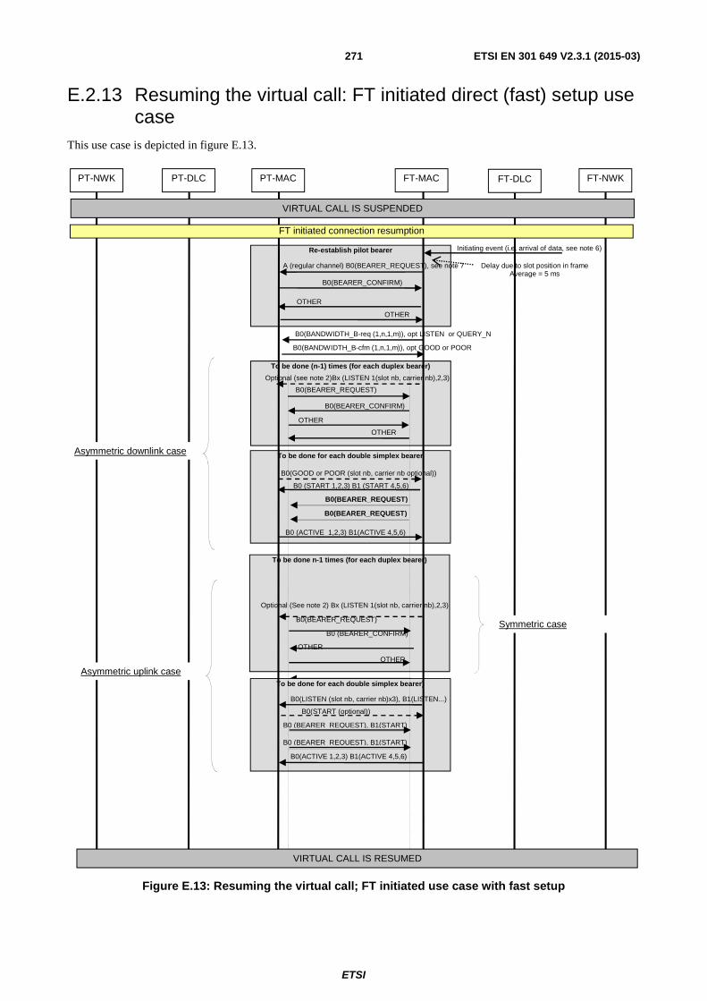
ETSI
ETSI EN 301 649 V2.3.1 (2015-03) 271
E.2.13 Resuming the virtual call: FT initiated direct (fast) setup use case
This use case is depicted in figure E.13.
Figure E.13: Resuming the virtual call; FT initiated use case with fast setup
To be done n-1 times (for each duplex bearer)
Optional (See note 2) Bx (LISTEN 1(slot nb, carrier nb),2,3) B0(BEARER_REQUEST)
B0 (BEARER_CONFIRM) OTHER
OTHER
To be done for each double simplex bearer)
B0(LISTEN (slot nb, carrier nb)x3), B1(LISTEN...) B0(START (optional))
B0(ACTIVE 1,2,3) B1(ACTIVE 4,5,6)
Re-establish pilot bearer
To be done for each double simplex bearer
To be done (n-1) times (for each duplex bearer)
FT-NWK FT-DLC FT-MAC PT-MAC PT-DLC PT-NWK
VIRTUAL CALL IS SUSPENDED
B0(BEARER_CONFIRM)
OTHER OTHER
A (regular channel) B0(BEARER_REQUEST), see note 7
B0(BANDWIDTH_B-req (1,n,1,m)), opt LISTEN or QUERY_N B0(BANDWIDTH_B-cfm (1,n,1,m)), opt GOOD or POOR
B0(BEARER_REQUEST) B0(BEARER_CONFIRM)
OTHER OTHER
B0(GOOD or POOR (slot nb, carrier nb optional)) B0 (START 1,2,3) B1 (START 4,5,6)
B0 (ACTIVE 1,2,3) B1(ACTIVE 4,5,6)
VIRTUAL CALL IS RESUMED
FT initiated connection resumption
Asymmetric downlink case
Asymmetric uplink case
B0(BEARER_REQUEST)
B0(BEARER_REQUEST)
Initiating event (i.e. arrival of data, see note 6)
Delay due to slot position in frame Average = 5 ms
B0 (BEARER_REQUEST), B1(START)
B0 (BEARER_REQUEST), B1(START)
Symmetric case
Optional (see note 2)Bx (LISTEN 1(slot nb, carrier nb),2,3)

ETSI
ETSI EN 301 649 V2.3.1 (2015-03) 272
NOTE 1: FT initiated direct (fast) setup for resuming a call is the only case where the initial (pilot) bearer setup is initiated by the FT.
NOTE 2: LISTEN command sent FT ⇒ PT is in practice mandatory (quasi-mandatory) to perform the setup of additional duplex. If no LISTEN is sent, the PT can only perform the setup after the expiration of a timer and over the scan sequence. If LISTEN has been sent (normal case), the setup can be done in any slot/carrier (not only on the scan sequence).
NOTE 3: Depending on the case, the FT could decide the carrier/slot directly of could use channel list proposals sent by the PP. If the use case is a resume after short time suspension, and the FT could reuse the channels used in last active stage, then the FT does not need to rely on PT information. The fastest implementation possible for this use case, sends the LISTEN command in the same frame as the Bandwidth FT ⇒ PT message. For other cases, i.e. resume after long time suspension, or impossibility to reuse the carriers used last time, then the FT retrieves and uses PT channel list information. The PT sends this information by means of the commands GOOD or POOR. This can be done spontaneously by the PT, or wait until the FT interrogates it with the QUERY_N command. The earliest convenient point for sending PT channel list info is the frame carrying the bandwidth PT ⇒ FT message. The following frame could carry the LISTEN commands if the FT is enough fast to calculate the channels. Note that this process delays the setup at least by one frame compared to the "resume after short time of suspension".
NOTE 4: Similar procedure applies to the setup of double simplex upstream bearers, with the difference that here the LISTEN command is mandatory (there is no timer option). The setup can be done in any slot/carrier (not only on the scan sequence).
NOTE 5: Similar procedure applies to the setup of double simplex downstream bearers, with the difference that here the FT sends the command START (on a duplex bearer) to indicate the channel selection that will be used in the setup. The setup can be done in any slot/carrier (not only on the scan sequence).
NOTE 6: The triggering event may be the reception of data to be transmitted downstream, but not only. For example, if the FT had interrupted a PT that was sending data downstream, or the FT rejected an access request from a PT (due to resource allocation decisions), the FT will resume the connection with upstream direction when its resource allocation algorithm decides to grant resources to such PT.
NOTE 7: The FT access request may be on the on arbitrary slot/carriers if selective fast setup is used and specific slots / carriers have been indicated to the PT. In any other cases (complete fast setup mode, or no specific information on carriers), the access request has to be on the fast setup scan sequence (PT receiving scan sequence).
E.2.14 Resuming the virtual call: FT initiated use case using paging
This use case is depicted in figures E.14 and E.14a.
Figure E.14: Resuming the virtual call; FT initiated use case using paging (MAC paging succeeds)
FT-NWK FT-DLC FT-MAC PT-MAC PT-DLC PT-NWK
MAC_resume page (ECN)
VIRTUAL CALL IS SUSPENDED
Using MAC resume paging procedure (MAC resume paging succeeds)
SEE PT INITIATED VIRTUAL CALL RESUMPTION (clause E.2.12) but with bandwidth messages reversed (see note 3)
A (B-field setup) B0(BEARER_REQUEST)
MAC
Pagi
bearer request received before end of timer
Initiating event (i.e. arrival of data)

ETSI
ETSI EN 301 649 V2.3.1 (2015-03) 273
Figure E.14a: Resuming the virtual call; FT initiated use case using paging (MAC paging fails and LCE paging has to be used)
NOTE 1: There are two diagrams according to whether the MAC resume paging succeeds or fails.
NOTE 2: In case the MAC resume fails, the arrival of the MAC_CO_DATA-req message at MAC layer on PT side (i.e. to send LCE-PAGE-RESPONSE) triggers a PT initiated connection resumption at MAC (see clause 10.3.1.2 and ETSI EN 300 175-5 [5], clause 14.5).
NOTE 3: PT initiated virtual call resumption procedure (clause E.2.12) is used as part of the FT initiated virtual call resumption, but with one difference: the Bandwidth messages are reversed (the Bandwidth request is sent by FT and the Bandwidth confirm by PT). As a consequence of this, the earliest point to start the setting of additional bearers is when the Bandwidth request has been sent (because the FT sends it).
NOTE 4: The FT may resume an asymmetric connection either in downlink or uplink directions.
NOTE 5: When MAC layer paging fails, the ME contacts LCE to send the paging.
MAC layer paging failed, use of LCE-REQUEST-PAGE
FT-NWK FT-DLC FT-MAC PT-MAC PT-DLC PT-NWK
MAC_resume page (ECN)
VIRTUAL CALL IS SUSPENDED
SEE PT INITIATED VIRTUAL CALL RESUMPTION (clause E.2.12) but with bandwidth messages reversed (see note 3)
The MAC resume paging procedure fails
LCE-REQUEST-PAGE (LCE=111 (Resume paging))
LCE-PAGE-RESPONSE (Resume paging) (over the resumed connection)
DL_DATA-req MAC_CO_DATA-req
A (B-field setup) B0(BEARER_REQUEST)
MAC Pagin
g wind
Initiating event (i.e. arrival of data)
Timer exp.
Delay
LCE Paging Window delay

ETSI
ETSI EN 301 649 V2.3.1 (2015-03) 274
E.2.15 PT initiated resume rejected by FT This use case is depicted in figure E.15.
Figure E.15: PT initiated resume rejected by FT
NOTE 1: If the FT is still congested, the Resume can be rejected by the FT a second time, a third time, etc. The Waiting time WtB should be increased (congestion avoidance) each time according to formulae in annex A.
NOTE 2: During the waiting time (WtB), the FT may start an FT initiated resume at any time during WtB waiting. A good designed FT could do that if the congestion situation that motivated the rejection ends before WtB. It is not required to have data to send downstream to initiate the FT resume.
Repetition of the process
Re-establish pilot bearer
Release of Pilot bearer
FT-NWK FT-DLC FT-MAC PT-MAC PT-DLC PT-NWK
VIRTUAL CALL IS SUSPENDED
B0(BEARER_CONFIRM)
OTHER OTHER
A (B-field setup) B0(BEARER_REQUEST)
B0(BANDWIDTH_B-req (1,n,1,m)) B0(BANDWIDTH_B-cfm (0,0,reason,0))
B0(RELEASE) Optional B0(RELEASE) (Crossed release)
B0 (RELEASE) (if no Crossed release)
PT initiated connection resumption
B0(BEARER_CONFIRM)
OTHER OTHER
A (B-field setup) B0(BEARER_REQUEST)
B0(BANDWIDTH_B-req 1,n,1,m)) B0(BANDWIDTH_B-cfm (x,x,x,x))
Timer WtB Optionally: the FT could initiate an FT resume during this time
Waiting Time B

ETSI
ETSI EN 301 649 V2.3.1 (2015-03) 275
E.2.16 Stay alive procedure (PT initiated) This use case is depicted in figure E.16.
Figure E.16: Stay alive procedure (PT initiated)
Release of the pilot bearer
Optional (Crossed release)
Re-establish pilot bearer
FT-NWK FT-DLC FT-MAC PT-MAC PT-DLC PT-NWK
VIRTUAL CALL IS SUSPENDED
B0(BEARER_CONFIRM)
OTHER OTHER
A (B-field setup) B0(BEARER_REQUEST)
B0(BANDWIDTH_B-req (0,0,5,0) B0(BANDWIDTH_B-cfm (0,0,5,0))
PT initiated connection resumption
A(any channel) B0(RELEASE) …
A(any channel) B0(RELEASE) …
A(any channel) B0(RELEASE) … A(regular channel) B0(RELEASE)
(Crossed Release)
SUCCESSFUL END OF PROCEDURE (RETURN TO SUSPEND STATE AND RESET OF TIMER T910)
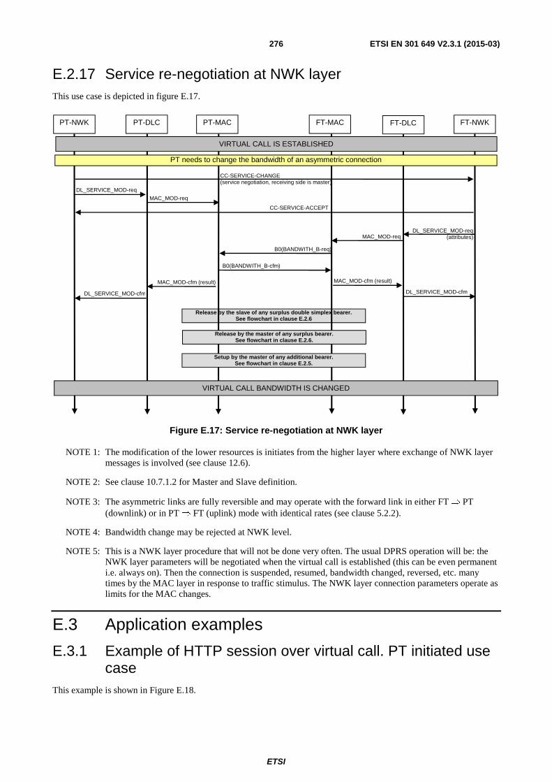
ETSI
ETSI EN 301 649 V2.3.1 (2015-03) 276
E.2.17 Service re-negotiation at NWK layer This use case is depicted in figure E.17.
Figure E.17: Service re-negotiation at NWK layer
NOTE 1: The modification of the lower resources is initiates from the higher layer where exchange of NWK layer messages is involved (see clause 12.6).
NOTE 2: See clause 10.7.1.2 for Master and Slave definition.
NOTE 3: The asymmetric links are fully reversible and may operate with the forward link in either FT ⇒ PT (downlink) or in PT ⇒ FT (uplink) mode with identical rates (see clause 5.2.2).
NOTE 4: Bandwidth change may be rejected at NWK level.
NOTE 5: This is a NWK layer procedure that will not be done very often. The usual DPRS operation will be: the NWK layer parameters will be negotiated when the virtual call is established (this can be even permanent i.e. always on). Then the connection is suspended, resumed, bandwidth changed, reversed, etc. many times by the MAC layer in response to traffic stimulus. The NWK layer connection parameters operate as limits for the MAC changes.
E.3 Application examples
E.3.1 Example of HTTP session over virtual call. PT initiated use case
This example is shown in Figure E.18.
Release by the slave of any surplus double simplex bearer. See flowchart in clause E.2.6
FT-NWK FT-DLC FT-MAC PT-MAC PT-DLC PT-NWK
DL_SERVICE_MOD-req
MAC_MOD-req
B0(BANDWITH_B-req)
B0(BANDWITH_B-cfm)
MAC_MOD-reqDL_SERVICE_MOD-req
(attributes)
VIRTUAL CALL IS ESTABLISHED
VIRTUAL CALL BANDWIDTH IS CHANGED
PT needs to change the bandwidth of an asymmetric connection
CC-SERVICE-CHANGE (service negotiation, receiving side is master)
CC-SERVICE-ACCEPT
MAC_MOD-cfm (result)
DL_SERVICE_MOD-cfm
MAC_MOD-cfm (result) DL_SERVICE_MOD-cfm
Release by the master of any surplus bearer. See flowchart in clause E.2.6.
Setup by the master of any additional bearer. See flowchart in clause E.2.5.

ETSI
ETSI EN 301 649 V2.3.1 (2015-03) 277
PT FT
CC-SETUP (DPRS, type, bandwidth)
AUTH-REQUEST (store DCK)
AUTH-REPLY
CIPHER-REQUEST
CC-CONNECT (DPRS, type, bandwidth)
HTTP-REQUEST (POST) <message>
HTTP-RESPONSE "Success"
CC-RELEASE
CC-RELEASE-COM
U-plane
MAC SUSPEND (no data)
MAC RESUME (upstream)
U-plane (IP(TCP(HTTP-REQUEST (POST) )))<message>
SUSPEND (no data)
MAC RESUME (downstream)
U-plane (IP(TCP(HTTP-RESPONSE) )))<message>
U-plane (IP(TCP(HTTP-RESPONSE) )))<message>
SUSPEND (no data)
DPRS Logical connection
Physical connection
Timer T903
FT timer (not standarized)
MAC RESUME (signaling only)
MAC PILOT BEARER SETUP
The connection becomes DPRS at this point
MAC RELEASE
Figure E.18: Example of HTTP session over virtual call. PT initiated use case
NOTE 1: MAC RESUME (upstream/downstream) stands for MAC resume paging followed by a bandwidth negotiation and establishment of an asymmetric uplink/downlink virtual call 1+n/n+1. MAC RESUME (signalling only) stands for MAC resume paging followed by a bandwidth negotiation and establishment of a symmetric virtual call 1+1.
NOTE 2: The FP could be linked to a home gateway connected to an external HTTP server.

ETSI
ETSI EN 301 649 V2.3.1 (2015-03) 278
E.4 Optimal sequences and time diagrams
E.4.1 Parallel execution and optimal timing of complex operations The diagrams presented in clause E.2 show the different operations needed for each procedure. However they do not cover the timing and possible parallel execution of operations. The timing sequence for each procedure depends on the real capabilities of the implementation. The rules that cover the possibilities for parallel execution of operations and the "early start" point of each of them are described in clause 10 of the present document. Implementers are free to design the best possible sequence of operations according to the technical capabilities of the implementations.
This clause shows the optimal possible sequences for three basic operations, assuming that implementation does not introduce any additional constrain due to software response time or other reason. The importance of these optimal sequences is dual: first, they may be used as starting point for building real implementation sequences (adding the extra time needed for the implementation constrains in each step), and second, they determine the intrinsic delay of DECT as a technology in the channel access operation. This delay is, as shown in the diagrams, 15 ms for the first bearer ready to transmit. This parameter is relevant for comparative evaluation of DECT versus other packet technologies.
The number of possible time sequences is nearly infinite, depending not only on the different options of each procedure, but also of implementation constrains. Each implementer should build its own implementation sequences according to the real implementation capabilities. Therefore, this clause is limited to three examples covering the following cases:
• PT initiated resume of upstream 9+1 connection.
• FT initiated direct (fast setup) resume of downstream 1+9 connection.
• PT initiated stay alive.
In all cases, the diagrams show the successful case (successfully completion of all operations) for ideal implementations. It is also assumed that the implementations support conditional link of operations, and that start all operations in the earliest possible starting point (according to the rules described in clause 10).
E.4.2 Time diagram 1: optimal sequence for PT initiated resume asymmetric uplink
The time diagram in figure E.19 shows the optimal implementation sequence for the use case of PT initiated connection resumption requesting asymmetric uplink bandwidth. The bandwidth request is granted by the FT.
NOTE 1: The example assumes that the slots are double or long (12 slots per frame), and all of them starts always in even positions in the frame. Slots 16 and 17 are selected as duplex pilot bearer.

ETSI
ETSI EN 301 649 V2.3.1 (2015-03) 279
Figure E.19: Time diagram 1: optimal sequence for PT initiated resume asymmetric uplink
NOTE 2: This diagram shows the best possible implementation without any extra delay due to implementation constrains.
NOTE 3: The average delay for starting the process is 5 ms. Depending on the position of the usable slot in frame and when the initiating event happens, the delay ranges from 0 to 12 double slots = 0 to 10 ms, average 5 ms.
NOTE 4: The example assumes that the FT could set directly the channels without consultation to the PT (resume after a short time of suspension and the channels used in last active stage can be reused). Note that this is a case that will happen very often.
NOTE 5: U-plane transmission can start at 15 ms over one bearer at triggering event. This is the basic intrinsic access delay of DECT.
Frame N+3, slot 0
Frame N+2, slot 12
Frame N+2, slot 0
Frame N, slot 12
slot 16, etc slot 14
Frame N+1, slot 0
Average delay due to slot position in frame: average = 5ms.
FT-NWK FT-DLC FT-MAC PT-MAC PT-DLC PT-NWK
VIRTUAL CALL IS SUSPENDED
VIRTUAL CALL IS RESUMED AND AT FULL BANDWIDTH
Use case: PT initiated connection resumption requesting asymmetric uplink bandwidth, m+n =9+1 that is granted by the FT.
Frame N+1, slot 12
A (B-field setup) B0 (Bearer.req) B1 (Bandwidth (1,m,1,n) , opt B3 (Bearer.req)
A (any channel) B0 (Bearer.cfm) B1 (Bandwidth.cfm (1,m,1,n) , opt B3 (Bearer.cfm), B2 (LISTEN 1,2,3) , B4 (LISTEN 4,5,6)
Initiating event (i.e. arrival of data)
A-field (any channel=other) B-field: U-plane (in clear) => U-plane transmission may start in this slot. Note that this is the “Other”
A-field (any channel=other) B0 (Bearer quality), B1 (ACTIVE 1,2,3) B2 (ACTIVE 4,5,5,6) B3-Bn (U-plane Ipf) Note that this is the 2nd “Other” and should be in clear
First possibility for U-plane transmission happens at 15 ms of the triggering event. This is the intrinsic delay of DECT as a technology
B0 (Bearer.req) opt B3 (Bearer.req) (this is the 1st slot of double simplex bearer 1) B0 (Bearer.req) opt B3 (Bearer.req) (double simplex bearer 2, 1st slot) B0 (Bearer.req) opt B3 (Bearer.req) (double simplex bearer 3, 1st slot)
B0 (Bearer.req) opt B3 (Bearer.req) (double simplex bearer 4, 2nd slot)
This is the earliest point for initiate a setup of double simplex bearers
B0 (Bearer.req) opt B3 (Bearer.req) (this is the 2st slot of double simplex bearer 1) B0 (Bearer.req) opt B3 (Bearer.req) (double simplex bearer 2, 2nd slot) B0 (Bearer.req) opt B3 (Bearer.req) (double simplex bearer 3, 2nd slot)
B0 (Bearer.req) opt B3 (Bearer.req) (double simplex bearer 4, 1 st slot)
This is the earliest point to send the ACTIVE
B-field: U-plane (in clear)
B-field: U-plane (in clear)
B-field: U-plane (in clear) B-field: U-plane (in clear)
B-field: U-plane (in clear) B-field: U-plane (in clear) B-field: U-plane (in clear) B-field: U-plane (in clear)
A-field (any channel) B-field: U-plane (if call was encrypted before the suspend, this bearer is ENCRYPTED)
B-field: U-plane (ENCRYPTED (if the call is encrypted))
A-field (any channel) B0 (Bearer quality), B1-Bn (U-plane Ipf) (if the call was encrypted before the suspend, this bearer is ENCRYPTED)
If ACTIVE has been received OK, transmission on double simplex bearers can start HERE
Encryption of double simplex starts HERE (if the call is encrypted, see note 10)

ETSI
ETSI EN 301 649 V2.3.1 (2015-03) 280
NOTE 6: U-plane transmission over the first available double simplex bearer happens 5,83 ms later (20,83 ms after initial event). The worst-case of last double simplex bearer is carrying data on the second half 30 ms after initial event.
NOTE 7: In the optimal possible sequencing shown in this diagram, the implementation has ONE double slot (10/12) ms of reaction time in the worst case (i.e. between reception of BEARER confirm, BANDWIDTH confirm and LISTEN, and starting BEARER setup on the bearers indicated by the LISTEN). A practical implementation could require some extra ms of reaction time before starting BEARER request. This time (implementation specific delay) should be added to the intrinsic delays shown in the diagram.
NOTE 8: On the other hand, the FT has 5 ms (12 slots) for answering to the bearer setup, decide if the bandwidth can be accepted and provide LISTEN commands. The response can be "cached" for the easiest cases (i.e. no bandwidth scarcity, and reuse of slots/channels already used in the last active phase). In other cases, the FT could need extra time.
NOTE 9: Note that some operations are conditional to the success of others. Example: if the initial BEARER request fails (pilot), the Bandwidth negotiation and the additional bearers setup should be rolled back, and the process should start again. However, these should be exceptional cases, and the average timing (delays) of the system should be dominated by the successful case.
NOTE 10: The use of encryption depends on if the call is encrypted or not. The setting of the encryption and the possible passing of keys is a common property of the call, and does not need to be re-negotiated for each resume process. If the call was encrypted before the suspend, it should be encrypted after the resume (with the same key used before, and taken into account the variation of other ciphering inputs as the frame and LBN numbers). The encryption should start when noted. As general rule, there is one frame in clear for both, duplex ("other" frame) and double simplex. In applications where maximum confidentiality is a concern, there is the option of waiting for the encryption activation before sending data. This would add an extra delay of 10 ms.
E.4.3 Time diagram 2: optimal sequence for FT initiated (direct) resume; asymmetric downlink connection
The time diagram in figure E.20 shows the optimal implementation sequence for the use case of FT initiated connection resumption (direct), setting an asymmetric downlink connection. Slots 4 and 5 is selected as duplex = pilot bearer.

ETSI
ETSI EN 301 649 V2.3.1 (2015-03) 281
Figure E.20: Time diagram 2: optimal sequence for FT initiated (direct) resume; asymmetric downlink connection
NOTE 1: The example assumes that the slots are double or long (12 slots per frame), and all of them start always in even positions in the frame.
NOTE 2: The same comments done for the PT initiated case, are applicable here (changing the roles of PT ⇔ FT).
NOTE 3: The START channel list command is used here instead of LISTEN. The use of channel list (GOOD, POOR) messages sent by PT, is generally not needed in the easiest case of resume after a brief period of suspension (the FT reuses the channels). However, if the FT is not sure of the status of the channels, it may query the PT by means of the "QUERY_N" command. The PT may also provide spontaneously channel list info (GOOD, POOR) that the FT could use if needed.
Frame N+2, slot 12
Frame N+2, slot 0
Frame N+1, slot 12
Frame N, slot 0
slot 4, etc slot 2
Frame N, slot 12
Average delay due to slot position in frame: average = 5ms.
FT-NWK FT-DLC FT-MAC PT-MAC PT-DLC PT-NWK
VIRTUAL CALL IS SUSPENDED
VIRTUAL CALL IS RESUMED AND AT FULL BANDWIDTH
Use case: FT initiated connection resumption setting an asymmetric downlink connection of m+n = 9+1 bearers (min 1,1).
Frame N+1, slot 0
A (regular channel) B0 (Bearer.req) B1 (Bandwidth (1,n,1,m) , B2 START (1,2,3) opt B3 (Bearer.req), B4 START (4)
A (regular channel) B0 (Bearer.cfm) B1 (Bandwidth.cfm (1,n, 1, m) , opt B3 (Bearer.cfm), opt B2 GOOD/POOR (1,2,3) opt, B4 GOOD/POOR (4,5,6)
Initiating event (i.e. arrival of data)
A-field (any channel=other) B-field: U-plane (in clear) => U-plane transmission may start in this slot. Note that this is the 1st “Other”
A-field (any channel=other) B0 (Bearer quality), B1 (ACTIVE 1,2,3) B2 (ACTIVE 4) B3-Bn (U-plane Ipf) Note that this is the 2nd “Other” and should be in clear
First possibility for U-plane transmission happens at 15 ms of the triggering event. This is the intrinsic delay of DECT as a technology
B0 (Bearer.req) opt B3 (Bearer.req) (this is the 2nd slot (PT>FT) of double simplex bearer 1) B0 (Bearer.req) opt B3 (Bearer.req) (double simplex bearer 2, 2nd slot) B0 (Bearer.req) opt B3 (Bearer.req) (double simplex bearer 3, 2nd slot)
B0 (Bearer.req) opt B3 (Bearer.req) (double simplex bearer 4, 1st slot)
This is the earliest point for initiate a setup of double simplex bearers
B0 (Bearer.req) opt B3 (Bearer.req) (this is the 1st slot of double simplex bearer 1) B0 (Bearer.req) opt B3 (Bearer.req) (double simplex bearer 2, 1st slot) B0 (Bearer.req) opt B3 (Bearer.req) (double simplex bearer 3, 1st slot)
B0 (Bearer.req) opt B3 (Bearer.req) (double simplex bearer 4, 2nd slot)
This is the earliest point to send the ACTIVE
B-field: U-plane (in clear)
B-field: U-plane (in clear)
B-field: U-plane (in clear) B-field: U-plane (in clear)
B-field: U-plane (in clear) B-field: U-plane (in clear) B-field: U-plane (in clear) B-field: U-plane (in clear)
A-field (any channel) B-field: U-plane (if call was encrypted before the suspend, this bearer is ENCRYPTED)
B-field: U-plane (ENCRYPTED (if the call is encrypted))
A-field (any channel) B0 (Bearer quality), B1-Bn (U-plane Ipf) (if the call was encrypted before the suspend, this bearer is ENCRYPTED)
If ACTIVE has been received OK, U-plane transmission on double simplex bearers can start HERE
Encryption of double simplex starts HERE (if the call is encrypted, see note)

ETSI
ETSI EN 301 649 V2.3.1 (2015-03) 282
E.4.4 Time diagram 3: optimal sequence for PT initiated stay alive procedure
The temporized diagram in figure E.21 shows the optimal implementation sequence for the use case of PT initiated stay alive.
NOTE: The time divisions in the diagram refer to double slots (as in previous example).
Figure E.21: Time diagram 3: optimal sequence for PT initiated stay alive procedure
E.5 Implementation examples related to DPRS Interworking options
E.5.1 Example of possible solution to the use case of an Internet browser operating over Generic Encapsulation transport mechanism (clause B.8)
E.5.1.1 Description of the use case
Use case:
• General Purpose Internet browser in the PP with functionality similar to standard browsers.
Frame N+2, slot 0
Frame N, slot 12
slot 16, etc slot 14
Frame N+1, slot 0
Average delay to start = 5ms.
FT-NWK FT-DLC FT-MAC PT-MAC PT-DLC PT-NWK
VIRTUAL CALL IS SUSPENDED
SUCCESSFUL END OF PROCEDURE (RETURN TO SUSPEND STATE AND RESET OF TIMER T910)
Use case: PT initiated stay alive.
Frame N+1, slot 12
A (B-field setup) B0 (Bearer.req) B1 (Bandwidth (0,0,5,0) , opt B3 (Bearer.req)
A (any channel) B0 (Bearer.cfm) B1 (Bandwidth.cfm (0,0,5,0) , opt B3 (Bearer.cfm)
Initiating event: the ME of the PT decides to perform the stay alive procedure.
(the procedure shall be done before the expiration of the timer T910)
A-field (any channel=other) B0 (RELEASE). Note that this is the “Other” for the setup
A-field (any channel=other) B0 (RELEASE), (Crossed Release) Note that this is the 2nd “Other” for the setup
Total duration of the procedure = 15 + 5ms.

ETSI
ETSI EN 301 649 V2.3.1 (2015-03) 283
• Internet connectivity at FP.
• Air interface protocol is Generic Encapsulation Interworking (clause B.8).
• Multiple protocols and multiple TCP connections at the network side are supported.
Implementation: as indicated in clauses B.8 and B.2.1.1.4. The FP implements the Generic multiprotocol interworking to external IP networks as described in clause B.8.4.1.
E.5.1.1.1 Step-by-step use case description
The next paragraphs describe the step-by-step operation of an Internet browser over D-GMEP.
Step 1: Call setup
The user starts (or awakes) the browser application in the PP.
The PP establishes a DPRS call (any ME class) indicating Generic Media Interworking. The Generic media octets at IWU-attributes will carry a single initial command opening a context for the DNS protocol.
• Command = create context.
• Sequence nr = No.
• Chopping = No.
• Protocol = DNS (protocol id = 53).
• GMCI = it is left blank by the PP, it will be returned by the FP with any arbitrary number (1-127) not currently in use (typically 1 since it is the first context).
• The optional octet for control of TCP/UDP/IP connections will be used with the following content:
- IP source address = left blank by the PP, it will be returned by the FP.
- IP destination address = the IP address of the Domain name server.
- Source port number = left blank by the PP, it will be returned by the FP.
- Destination port number = the well-known port number of the Domain name server.
NOTE 1: In this specific case, it would be also possible to set the IP destination (IP address of the Domain name server) by the FP. But as we will see in step 4, this is not possible in general.
NOTE 2: The returned values of source address and port are in many cases not needed by the PP. But in some cases, the PP application may need to access then. This is why they are transmitted.
NOTE 3: It is also possible to establish at this stage two contexts to two different DNS servers, if wished.
Action at step 1
The DPRS call is established.
The FP Interworking creates a "context" that relations any traffic received over the D-GMEP link with GMCI=1 with a UDP "context" towards the DNS server.
Step 2: Initiation of browsing: DNS resolution
The user writes any URL in the browser.
The browser application performs the DNS resolution of the URL by sending a DNS protocol request over the opened context (GMCI=1). This will be mapped by the FP IWU to an UDP "context" towards the DNS server. The answer from the DNS server is mapped back over the same GMEP context towards the PP browser. The PP browser knows now the IP address.

ETSI
ETSI EN 301 649 V2.3.1 (2015-03) 284
Step 3: Initiation of browsing: First HTTP connection setup
The PP browser opens now a new GMEP context over the DPRS connection by executing a SERVICE CHANGE with the following parameters:
• Command = create context.
• Sequence nr = Yes.
• Chopping = Optional (this is independent to the example).
• Protocol = HTTP (protocol id = 80).
• GMCI = it is left blank by the PP, it will be returned by the FP with any arbitrary number.
• The optional octet for control of TCP/UDP/IP connections will be used with the following content:
- IP source address = left blank by the PP, it will be returned by the FP.
- IP destination address= the IP address of the HTTP server received in step 2.
- Source port number = left blank by the PP, it will be returned by the FP.
- Destination port number = the destination port of the HTTP connection (the number written in the browser (i.e. 1 080) or the default (80) if no number is provided).
NOTE 4: The previous context used by DNS is not released. It will be kept during the whole browsing session.
Actions at FP
At the reception of the Service change message, the FP IWU will open a TCP connection towards the destination server and will keep this connection open until it is explicitly closed by the PP (with a release context command), by the server, or by error.
Step 4: Browsing: exchange of HTTP data
The PP browser may send now any HTTP command to the Internet server in the same way it would do that over a TCP connection. The HTTP response reaches the browser over the same GMCI.
Step 5: Browsing: opening of further HTTP connections
The HTTP page that is being received from the server requires now to download further data from the same, or from other HTTP server. According to the normal browsing operation, if the data is from the same server and may be requested over the same TCP connection, then the existing HTTP context (GMCI=2) will be used. In any other case, new contexts and TCP connections will be opened.
The PP will repeat the steps 2 (DNS resolution) to resolve any URL address.
Then, it performs step 3 (to setup new HTTP contexts if needed) that would be mapped by the FP to new, independent, TCP connections.
Finally, the step 4 (exchanging the data) is performed over the different HTTP connections.
Step 6: Release of resources
6a: Release of resources by the PP
Use case: The PP browser has received all data and now decides to close any of the TCP connections. This is done by executing step 3 (service change) with the "release command". In the release command, there is no need to repeat the IP control octets. Let's assume that GMCI= 2 (HTTP) is the one to be released.
SERVICE CHANGE: IWU-Attributes:
• Command = release context.
• Sequence nr = Yes (same value as at context creation).

ETSI
ETSI EN 301 649 V2.3.1 (2015-03) 285
• Chopping = same value as at context creation (this is irrelevant for the operation).
• Protocol = HTTP (=80) (same value as at context creation).
• GMCI = the value allocated at context creation (i.e. 2).
Action by the FP: The FP closes the TCP connection associated to GMCI=2 and frees this GMCI number for further use.
6b: Release of resources by the FP
Use case: The far end server decides to close a TCP connection. When the FP receives the termination command, it completes the TCP closure as usual, and also closes the associated context over the D-GMEP by executing a SERVICE CHANGE with the "release command". The PP application is now aware that the TCP connection has been closed by the server.
Command is similar to step 6a.
Step 7: Further protocols
The described solution is general and would support protocols other than HTTP. For instance, the browser may need to open an FTP connection for downloading, or it may wish to listen to the broadcast provided by an Internet radio using RTP. Any scenario may be supported as long as the limit of 128 TCP + 128 UDP contexts is not reached. In some cases, the opening of the context may be initiated by the FP side.
VoIP telephony calls may be also supported by opening the two necessary contexts (SIP and RTP).
The correct operation of the multiprotocol case requires the sequence control at Receiver side to be done by the interworking once the different data flows have been de-multiplexed.

ETSI
ETSI EN 301 649 V2.3.1 (2015-03) 286
Annex F (informative): Bibliography
• ETSI ETR 043: "Digital Enhanced Cordless Telecommunications (DECT); Common Interface (CI); Services and facilities requirements specification".
• ETSI TS 102 342: "Digital Enhanced Cordless Telecommunications (DECT); Cordless Multimedia Communication System; Open Data Access Profile (ODAP)".
• ETSI TS 102 265: "Digital Enhanced Cordless Telecommunications (DECT); DECT Access to IP networks".
• ETSI EN 300 757: "Digital Enhanced Cordless Telecommunications (DECT); Low Rate Messaging Service (LRMS) including Short Messaging Service (SMS)".
• ETSI EN 301 238: "Digital Enhanced Cordless Telecommunications (DECT); Data Services Profile (DSP); Isochronous data bearer services with roaming mobility (service type D, mobility class 2)".
• ETSI EN 300 765-1: "Digital Enhanced Cordless Telecommunications (DECT); Radio in the Local Loop (RLL) Access Profile (RAP); Part 1: Basic telephony services".
• ETSI EN 300 765-2: "Digital Enhanced Cordless Telecommunications (DECT); Radio in the Local Loop (RLL) Access Profile (RAP); Part 2: Advanced telephony services".
• ETSI TS 101 863: "Digital Enhanced Cordless Telecommunications (DECT); DECT/UMTS Interworking Profile (IWP)".
• ETSI TS 102 379: "Digital Enhanced Cordless Telecommunications (DECT); Fixed network Multimedia Message Service (F-MMS) Interworking Profile".
• ETSI TS 102 527-1: "Digital Enhanced Cordless Telecommunications (DECT); New Generation DECT; Part 1: Wideband speech".
• ETSI TS 102 527-2: "Digital Enhanced Cordless Telecommunications (DECT); New Generation DECT; Part 2: Support of transparent IP packet data".
• ETSI TS 102 527-3: "Digital Enhanced Cordless Telecommunications (DECT); New Generation DECT; Part 3: Extended wideband speech services".
• Recommendation ITU-T I.122: "Framework for frame mode bearer services".
• Recommendation ITU-T Q.931: "ISDN user-network interface layer 3 specification for basic call control".
• Recommendation ITU-T V.120: "Support by an ISDN of data terminal equipment with V-Series type interfaces with provision for statistical multiplexing".
• Recommendation ITU-T X.25: "Interface between Data Terminal Equipment (DTE) and Data Circuit-terminating Equipment (DCE) for terminals operating in the packet mode and connected to public data networks by dedicated circuit".
• Recommendation ITU-T X.263: "Information technology - Protocol identification in the Network Layer".
• Universal Serial Bus (USB) Specification (Compaq Computer Corporation, Intel Corporation, Microsoft Corporation, NEC Corporation).
• IETF RFC 3551: "RTP Profile for Audio and Video Conferences with Minimal Control".
• IETF RFC 2326: "Real Time Streaming Protocol (RTSP)".
• IETF RFC 3232: "Assigned Numbers: RFC 1700 is Replaced by an On-line Database".

ETSI
ETSI EN 301 649 V2.3.1 (2015-03) 287
History
Document history
V1.1.1 March 2000 Publication
V1.2.1 June 2001 Publication
V1.3.1 March 2003 Publication
V1.4.1 December 2004 Publication
V2.1.1 February 2010 Publication
V2.2.1 February 2012 Publication
V2.3.0 November 2014 EN Approval Procedure AP 20150321: 2014-11-21 to 2015-03-23
V2.3.1 March 2015 Publication