en 301 843-1 - v2.2.1 - electromagnetic compatibility … · 4.2.2 arrangements for test signals at...
TRANSCRIPT
ETSI EN 301 843-1 V2.2.1 (2017-11)
ElectroMagnetic Compatibility (EMC) standard for marine radio equipment and services;
Harmonised Standard for electromagnetic compatibility; Part 1: Common technical requirements
HARMONISED EUROPEAN STANDARD
ETSI
ETSI EN 301 843-1 V2.2.1 (2017-11) 2
Reference REN/ERM-EMC-385
Keywords EMC, harmonised standard, maritime, radio,
regulation
ETSI
650 Route des Lucioles F-06921 Sophia Antipolis Cedex - FRANCE
Tel.: +33 4 92 94 42 00 Fax: +33 4 93 65 47 16
Siret N° 348 623 562 00017 - NAF 742 C
Association à but non lucratif enregistrée à la Sous-Préfecture de Grasse (06) N° 7803/88
Important notice
The present document can be downloaded from: http://www.etsi.org/standards-search
The present document may be made available in electronic versions and/or in print. The content of any electronic and/or print versions of the present document shall not be modified without the prior written authorization of ETSI. In case of any
existing or perceived difference in contents between such versions and/or in print, the only prevailing document is the print of the Portable Document Format (PDF) version kept on a specific network drive within ETSI Secretariat.
Users of the present document should be aware that the document may be subject to revision or change of status. Information on the current status of this and other ETSI documents is available at
https://portal.etsi.org/TB/ETSIDeliverableStatus.aspx
If you find errors in the present document, please send your comment to one of the following services: https://portal.etsi.org/People/CommiteeSupportStaff.aspx
Copyright Notification
No part may be reproduced or utilized in any form or by any means, electronic or mechanical, including photocopying and microfilm except as authorized by written permission of ETSI.
The content of the PDF version shall not be modified without the written authorization of ETSI. The copyright and the foregoing restriction extend to reproduction in all media.
© ETSI 2017.
All rights reserved.
DECTTM, PLUGTESTSTM, UMTSTM and the ETSI logo are trademarks of ETSI registered for the benefit of its Members. 3GPPTM and LTE™ are trademarks of ETSI registered for the benefit of its Members and
of the 3GPP Organizational Partners. oneM2M logo is protected for the benefit of its Members.
GSM® and the GSM logo are trademarks registered and owned by the GSM Association.
ETSI
ETSI EN 301 843-1 V2.2.1 (2017-11) 3
Contents
Intellectual Property Rights ................................................................................................................................ 5
Foreword ............................................................................................................................................................. 5
Modal verbs terminology .................................................................................................................................... 6
1 Scope ........................................................................................................................................................ 7
2 References ................................................................................................................................................ 8
2.1 Normative references ......................................................................................................................................... 8
2.2 Informative references ........................................................................................................................................ 8
3 Definitions, symbols and abbreviations ................................................................................................... 9
3.1 Definitions .......................................................................................................................................................... 9
3.2 Symbols ............................................................................................................................................................ 10
3.3 Abbreviations ................................................................................................................................................... 10
4 General and operational requirements .................................................................................................... 11
4.1 Environmental profile ....................................................................................................................................... 11
4.2 Arrangements for test signals ........................................................................................................................... 11
4.2.0 General ........................................................................................................................................................ 11
4.2.1 Arrangements for test signals at the input of transmitters ........................................................................... 11
4.2.2 Arrangements for test signals at the output of transmitters ......................................................................... 12
4.2.3 Arrangements for test signals at the input of receivers ............................................................................... 12
4.2.4 Arrangements for test signals at the output of receivers ............................................................................. 12
4.2.5 Arrangements for testing transmitter and receiver together (as a system) .................................................. 13
4.3 RF exclusion band of radio communications equipment.................................................................................. 13
4.4 Narrow band responses of receivers or receivers which are part of transceivers ............................................. 14
4.5 Normal test modulation .................................................................................................................................... 14
5 Performance assessment ......................................................................................................................... 14
5.1 General ............................................................................................................................................................. 14
5.2 Equipment which can provide a continuous communication link .................................................................... 15
5.3 Equipment which does not provide a continuous communication link ............................................................ 15
5.4 Ancillary equipment ......................................................................................................................................... 16
5.5 Equipment classification .................................................................................................................................. 16
6 Performance criteria ............................................................................................................................... 17
6.0 General requirements ....................................................................................................................................... 17
6.1 Performance criteria A for continuous phenomena applied to transmitters and receivers................................ 17
6.2 Performance criteria B for transient phenomena applied to transmitters and receivers ................................... 17
6.3 Performance criteria C applied to power supply failure ................................................................................... 18
6.4 Performance check ........................................................................................................................................... 18
6.5 Performance criteria for equipment which does not provide a continuous communication link ...................... 18
6.6 Performance criteria for ancillary equipment tested on a stand alone basis ..................................................... 18
7 Applicability overview tables ................................................................................................................. 19
7.0 General ............................................................................................................................................................. 19
7.1 EMC emission .................................................................................................................................................. 19
7.2 Immunity .......................................................................................................................................................... 19
8 Testing for compliance with technical requirements .............................................................................. 20
8.0 Environmental conditions for testing ............................................................................................................... 20
8.1 Test configuration............................................................................................................................................. 20
8.2 Enclosure of ancillary equipment measured on a stand alone basis ................................................................. 20
8.2.0 Applicability ............................................................................................................................................... 20
8.2.1 Test description ........................................................................................................................................... 21
8.2.2 Test method ................................................................................................................................................ 21
8.2.3 Limits .......................................................................................................................................................... 21
8.3 DC power input/output ports ............................................................................................................................ 22
8.3.0 Applicability ............................................................................................................................................... 22
8.3.1 Test description ........................................................................................................................................... 22

ETSI
ETSI EN 301 843-1 V2.2.1 (2017-11) 4
8.3.2 Test method ................................................................................................................................................ 22
8.3.3 Limits .......................................................................................................................................................... 23
8.4 AC mains power input/output ports ................................................................................................................. 23
8.4.0 Applicability ............................................................................................................................................... 23
8.4.1 Test description ........................................................................................................................................... 23
8.4.2 Test method ................................................................................................................................................ 23
8.4.3 Limits .......................................................................................................................................................... 24
9 Test methods and levels for immunity tests ........................................................................................... 24
9.0 General ............................................................................................................................................................. 24
9.1 Test configuration............................................................................................................................................. 24
9.2 Radio frequency electromagnetic field (80 MHz to 2 700 MHz) ..................................................................... 25
9.2.0 Applicability ............................................................................................................................................... 25
9.2.1 Test description ........................................................................................................................................... 25
9.2.2 Test method ................................................................................................................................................ 25
9.2.3 Performance criteria .................................................................................................................................... 25
9.3 Electrostatic discharge ...................................................................................................................................... 26
9.3.0 Applicability ............................................................................................................................................... 26
9.3.1 Test description ........................................................................................................................................... 26
9.3.2 Test method ................................................................................................................................................ 26
9.3.3 Performance criteria .................................................................................................................................... 26
9.4 Fast transients, differential and common mode ................................................................................................ 26
9.4.0 Applicability ............................................................................................................................................... 26
9.4.1 Test description ........................................................................................................................................... 27
9.4.2 Test method ................................................................................................................................................ 27
9.4.3 Performance criteria .................................................................................................................................... 27
9.5 Radio frequency, common mode ...................................................................................................................... 27
9.5.0 Applicability ............................................................................................................................................... 27
9.5.1 Test description ........................................................................................................................................... 27
9.5.2 Test method ................................................................................................................................................ 28
9.5.3 Performance criteria .................................................................................................................................... 28
9.6 Power supply variations ................................................................................................................................... 28
9.6.0 Applicability ............................................................................................................................................... 28
9.6.1 Power supply short term variations ............................................................................................................. 28
9.6.1.1 Test description ..................................................................................................................................... 28
9.6.1.2 Test method ........................................................................................................................................... 29
9.6.1.3 Performance criteria .............................................................................................................................. 29
9.6.2 Power supply failure ................................................................................................................................... 29
9.6.2.1 Test description ..................................................................................................................................... 29
9.6.2.2 Test method ........................................................................................................................................... 29
9.6.2.3 Performance criteria .............................................................................................................................. 29
9.7 Surges ............................................................................................................................................................... 29
9.7.0 Applicability ............................................................................................................................................... 29
9.7.1 Test description ........................................................................................................................................... 29
9.7.2 Test method ................................................................................................................................................ 30
9.7.3 Performance criteria .................................................................................................................................... 30
Annex A (informative): Relationship between the present document and the essential requirements of Directive 2014/53/EU ......................................................... 31
Annex B (informative): Bibliography ................................................................................................... 33
Annex C (informative): Change history ............................................................................................... 34
History .............................................................................................................................................................. 35

ETSI
ETSI EN 301 843-1 V2.2.1 (2017-11) 5
Intellectual Property Rights
Essential patents
IPRs essential or potentially essential to the present document may have been declared to ETSI. The information pertaining to these essential IPRs, if any, is publicly available for ETSI members and non-members, and can be found in ETSI SR 000 314: "Intellectual Property Rights (IPRs); Essential, or potentially Essential, IPRs notified to ETSI in respect of ETSI standards", which is available from the ETSI Secretariat. Latest updates are available on the ETSI Web server (https://ipr.etsi.org/).
Pursuant to the ETSI IPR Policy, no investigation, including IPR searches, has been carried out by ETSI. No guarantee can be given as to the existence of other IPRs not referenced in ETSI SR 000 314 (or the updates on the ETSI Web server) which are, or may be, or may become, essential to the present document.
Trademarks
The present document may include trademarks and/or tradenames which are asserted and/or registered by their owners. ETSI claims no ownership of these except for any which are indicated as being the property of ETSI, and conveys no right to use or reproduce any trademark and/or tradename. Mention of those trademarks in the present document does not constitute an endorsement by ETSI of products, services or organizations associated with those trademarks.
Foreword This Harmonised European Standard (EN) has been produced by ETSI Technical Committee Electromagnetic compatibility and Radio spectrum Matters (ERM).
The present document has been prepared under the Commission's standardisation request C(2015) 5376 final [i.10] to provide one voluntary means of conforming to the essential requirements of Directive 2014/53/EU on the harmonisation of the laws of the Member States relating to the making available on the market of radio equipment and repealing Directive 1999/5/EC [i.4].
Once the present document is cited in the Official Journal of the European Union under that Directive, compliance with the normative clauses of the present document given in table A.1 confers, within the limits of the scope of the present document, a presumption of conformity with the corresponding essential requirements of that Directive, and associated EFTA regulations.
The present document is part 1 of a multi-part deliverable covering the ElectroMagnetic Compatibility (EMC) standard for marine radio equipment and services, as identified below:
Part 1: "Common technical requirements";
Part 2: "Specific conditions for VHF radiotelephone transmitters and receivers";
Part 4: "Specific conditions for Narrow-Band Direct-Printing (NBDP) NAVTEX receivers";
Part 5: "Specific conditions for MF/HF radiotelephone transmitters and receivers";
Part 6: "Specific conditions for Earth Stations on board Vessels operating in frequency bands above 3 GHz".
Part 7: "Specific conditions for Maritime Broadband Radiolink equipment".
ETSI
ETSI EN 301 843-1 V2.2.1 (2017-11) 6
National transposition dates
Date of adoption of this EN: 17 October 2017
Date of latest announcement of this EN (doa): 31 January 2018
Date of latest publication of new National Standard or endorsement of this EN (dop/e):
31 July 2018
Date of withdrawal of any conflicting National Standard (dow): 31 July 2019
Modal verbs terminology In the present document "shall", "shall not", "should", "should not", "may", "need not", "will", "will not", "can" and "cannot" are to be interpreted as described in clause 3.2 of the ETSI Drafting Rules (Verbal forms for the expression of provisions).
"must" and "must not" are NOT allowed in ETSI deliverables except when used in direct citation.
ETSI
ETSI EN 301 843-1 V2.2.1 (2017-11) 7
1 Scope The present document contains the common requirements for marine radio communications equipment and associated ancillary equipment, in respect of ElectroMagnetic Compatibility (EMC).
The provisions of the present document apply to marine radio equipment not covered in the scope of the Council Directive on marine equipment (the "Marine Equipment Directive" 96/98/EC [i.5]).
Product dependent arrangements necessary to perform the EMC tests on dedicated types of marine radio communications equipment, and the assessment of test results, are detailed in the appropriate product related parts of the present document.
The present document, together with the product related part, specifies the applicable EMC tests, the methods of measurement, the limits and the performance criteria for marine radio equipment and associated ancillary equipment.
In case of differences (for instance concerning special conditions, definitions, abbreviation) between the present document and the relevant product related part of the present document, the product related part takes precedence.
For the further content of the present document, the expression "radio equipment" is taken to mean marine radio communications equipment, in each individual case.
Technical specifications related to the antenna port of radio equipment and emissions from the enclosure port of radio equipment and combinations of radio and associated ancillary equipment are not included in the present document. Such technical specifications are normally found in the relevant product standards for the effective use of the radio spectrum.
The environment classification used in the present document is maritime, as defined in IEC EN 60945 [1].
Marine radio communications equipment meeting the EMC requirements set out in IEC EN 60945 [1] is deemed to meet also the EMC requirements for the residential, commercial and light industrial environment as defined in IEC EN 61000-6-3 [i.1] and IEC EN 61000-6-1 [i.2].
The EMC requirements have been selected to ensure an adequate level of compatibility for apparatus intended to be used in the maritime environment. The levels, however, do not cover extreme cases which may occur in any location but with low probability of occurrence.
Compliance of radio equipment to the requirements of the present document does not signify compliance to any requirements related to spectrum management or to the use of the equipment (licensing requirements).
Compliance to the requirements of the present document does not signify compliance to any safety requirements. However, it is the responsibility of the assessor of the equipment to record in the test report any observations regarding the test sample becoming dangerous or unsafe as a result of the application of the tests called for in the present document.
NOTE: The relationship between the present document and essential requirements of article 3.1b of Directive 2014/53/EU [i.4] is given in annex A.
In addition to the present document, other ENs that specify technical requirements in respect of essential requirements under other parts of article 3 of the Radio Equipment Directive [i.4] may apply to equipment within the scope of the present document.
ETSI
ETSI EN 301 843-1 V2.2.1 (2017-11) 8
2 References
2.1 Normative references References are specific, identified by date of publication and/or edition number or version number. Only the cited version applies.
Referenced documents which are not found to be publicly available in the expected location might be found at https://docbox.etsi.org/Reference/.
NOTE: While any hyperlinks included in this clause were valid at the time of publication, ETSI cannot guarantee their long term validity.
The following referenced documents are necessary for the application of the present document.
[1] IEC EN 60945 (2002) + Corrigendum 1 (2008): "Maritime navigation and radiocommunication equipment and systems - General requirements - Methods of testing and required test results".
[2] CISPR 16-1-1 (2015): "Specification for radio disturbance and immunity measuring apparatus and methods - Part 1-1: Radio disturbance and immunity measuring apparatus - Measuring apparatus".
[3] IEC EN 61000-4-2 (2008): "Electromagnetic compatibility (EMC) - Part 4-2: Testing and measurement techniques - Electrostatic discharge immunity test".
[4] IEC EN 61000-4-3 (2006 + Amendment 1:2007 +Amendment 2:2010): "Electromagnetic compatibility (EMC) - Part 4-3: Testing and measurement techniques - Radiated, radio-frequency, electromagnetic field immunity test".
[5] IEC EN 61000-4-4 (2012): "Electromagnetic compatibility (EMC) - Part 4-4: Testing and measurement techniques - Electrical fast transient/burst immunity test".
[6] IEC EN 61000-4-5 (2014): "Electromagnetic compatibility (EMC) - Part 4-5: Testing and measurement techniques - Surge immunity test".
[7] IEC EN 61000-4-6 (2013): "Electromagnetic compatibility (EMC) - Part 4-6: Testing and measurement techniques - Immunity to conducted disturbances, induced by radio-frequency fields".
2.2 Informative references References are either specific (identified by date of publication and/or edition number or version number) or non-specific. For specific references, only the cited version applies. For non-specific references, the latest version of the referenced document (including any amendments) applies.
NOTE: While any hyperlinks included in this clause were valid at the time of publication, ETSI cannot guarantee their long term validity.
The following referenced documents are not necessary for the application of the present document but they assist the user with regard to a particular subject area.
[i.1] IEC EN 61000-6-3 (2007) + A1 (2011): "Electromagnetic compatibility (EMC) - Part 6-3: Generic standards - Emission standard for residential, commercial and light-industrial environments".
[i.2] IEC EN 61000-6-1 (2007): "Electromagnetic compatibility (EMC) - Part 6-1: Generic standards - Immunity for residential, commercial and light-industrial environments".
[i.3] Void.
[i.4] Directive 2014/53/EU of the European Parliament and of the Council of 16 April 2014 on the harmonisation of the laws of the Member States relating to the making available on the market of radio equipment and repealing Directive 1999/5/EC.

ETSI
ETSI EN 301 843-1 V2.2.1 (2017-11) 9
[i.5] Council Directive 96/98/EC of 20 December 1996 on marine equipment.
[i.6] IEC EN 60050-161 (1990): "International Electrotechnical Vocabulary. Chapter 161: Electromagnetic compatibility".
[i.7] CEPT/ERC Recommendation 74-01 (2011): "Unwanted emissions in the spurious domain".
[i.8] Void.
[i.9] IMO Convention: "International Convention for the Safety of Life at Sea (SOLAS)".
[i.10] Commission Implementing Decision C(2015) 5376 final of 4.8.2015 on a standardisation request to the European Committee for Electrotechnical Standardisation and to the European Telecommunications Standards Institute as regards radio equipment in support of Directive 2014/53/EU of the European Parliament and of the Council.
3 Definitions, symbols and abbreviations
3.1 Definitions For the purposes of the present document, the following terms and definitions apply:
ancillary equipment: equipment (apparatus), used in connection with a receiver, transmitter or transceiver is considered as an ancillary equipment (apparatus) if:
• the equipment is intended for use in conjunction with a receiver or transmitter to provide additional operational and/or control features to the radio equipment, (e.g. to extend control to another position or location); and
• the equipment cannot be used on a stand alone basis to provide user functions independently of a receiver or transmitter; and
• the receiver or transmitter to which it is connected, is capable of providing some intended operation such as transmitting and/or receiving without the ancillary equipment (i.e. it is not a sub-unit of the main equipment essential to the main equipment basic functions).
artificial antenna: non-reactive, non-radiating dummy load equal to the nominal impedance of the antenna port
NOTE: For the purpose of EMC tests, the antenna port(s) of the Equipment Under Test (EUT) are terminated with a non-radiating 50 Ω termination (artificial antenna) unless there is a requirement to apply a Radio Frequency (RF) input signal to the receiver antenna port.
continuous phenomena (continuous disturbance): electromagnetic disturbance, the effects of which on a particular device or equipment cannot be resolved into a succession of distinct effects
NOTE: See IEC EN 60050-161 [i.6].
enclosure port: physical boundary of the apparatus through which electromagnetic fields may radiate or impinge
NOTE: In the case of integral antenna equipment, this port is inseparable from the antenna port.
integral antenna: antenna designed to be connected directly to the equipment with or without the use of an external connector and considered to be part of the equipment
NOTE: An integral antenna may be fitted internally or externally to the equipment. An antenna which may not be removed during the tests, according to the manufacturer's statement.
manufacturer: manufacturer of the equipment, or his authorized representative, or an equipment manufacturer to the European market
mobile equipment: marine receiver, transmitter or transmitter/receiver (transceiver) intended for installation and use onboard ships
ETSI
ETSI EN 301 843-1 V2.2.1 (2017-11) 10
operating frequency range: range(s) of radio frequencies covered by the Equipment Under Test (EUT) without any change of units
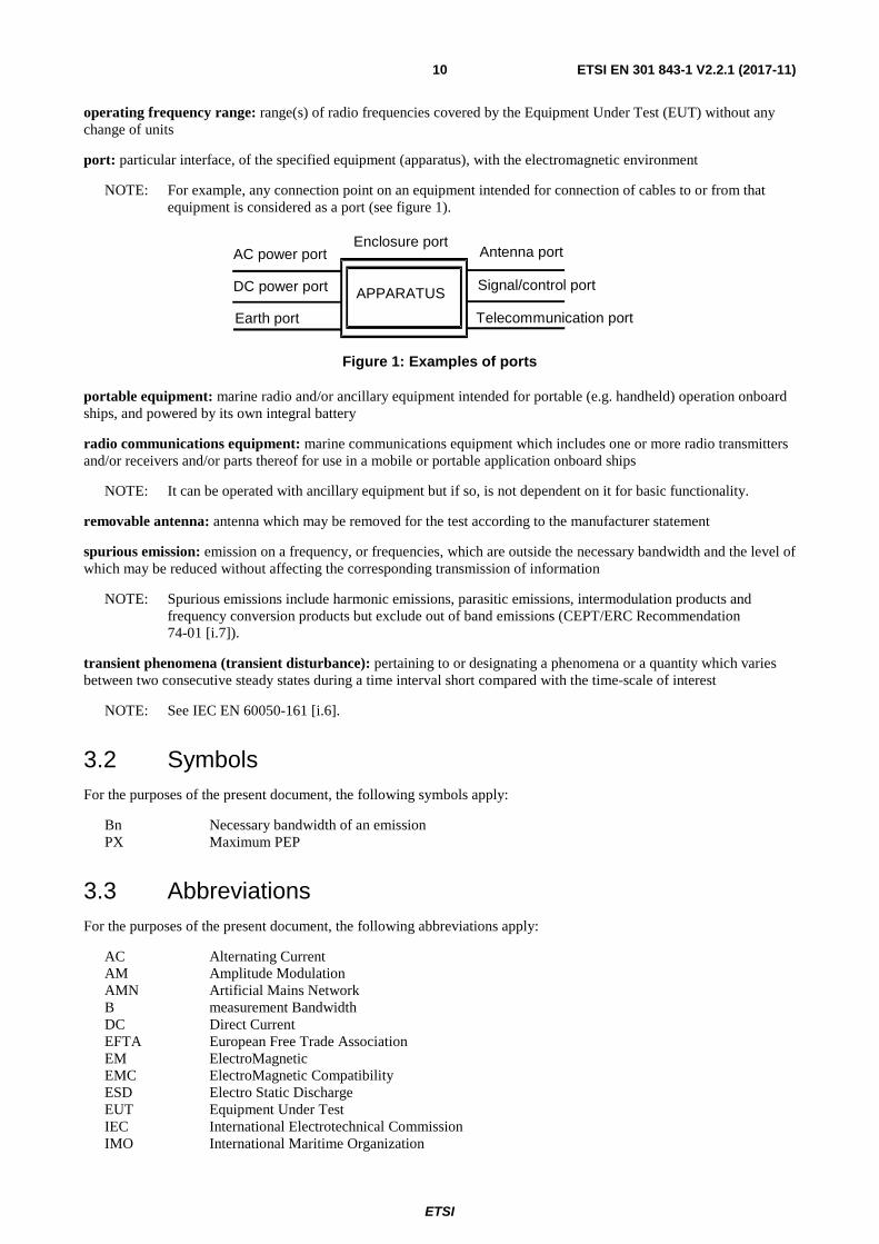
port: particular interface, of the specified equipment (apparatus), with the electromagnetic environment
NOTE: For example, any connection point on an equipment intended for connection of cables to or from that equipment is considered as a port (see figure 1).
DC power port
AC power port Enclosure port
Antenna port
Signal/control port APPARATUS
Telecommunication port Earth port
Figure 1: Examples of ports
portable equipment: marine radio and/or ancillary equipment intended for portable (e.g. handheld) operation onboard ships, and powered by its own integral battery
radio communications equipment: marine communications equipment which includes one or more radio transmitters and/or receivers and/or parts thereof for use in a mobile or portable application onboard ships
NOTE: It can be operated with ancillary equipment but if so, is not dependent on it for basic functionality.
removable antenna: antenna which may be removed for the test according to the manufacturer statement
spurious emission: emission on a frequency, or frequencies, which are outside the necessary bandwidth and the level of which may be reduced without affecting the corresponding transmission of information
NOTE: Spurious emissions include harmonic emissions, parasitic emissions, intermodulation products and frequency conversion products but exclude out of band emissions (CEPT/ERC Recommendation 74-01 [i.7]).
transient phenomena (transient disturbance): pertaining to or designating a phenomena or a quantity which varies between two consecutive steady states during a time interval short compared with the time-scale of interest
NOTE: See IEC EN 60050-161 [i.6].
3.2 Symbols For the purposes of the present document, the following symbols apply:
Bn Necessary bandwidth of an emission PX Maximum PEP
3.3 Abbreviations For the purposes of the present document, the following abbreviations apply:
AC Alternating Current AM Amplitude Modulation AMN Artificial Mains Network B measurement Bandwidth DC Direct Current EFTA European Free Trade Association EM ElectroMagnetic EMC ElectroMagnetic Compatibility ESD Electro Static Discharge EUT Equipment Under Test IEC International Electrotechnical Commission IMO International Maritime Organization
ETSI
ETSI EN 301 843-1 V2.2.1 (2017-11) 11
MF/HF Medium Frequency/High Frequency NAVTEX Navigational Telex NBDP Narrow Band Direct Printing RF Radio Frequency rms root mean square VHF Very High Frequency
4 General and operational requirements
4.1 Environmental profile The technical requirements of the present document apply under the environmental profile for operation of the equipment, which shall be declared by the manufacturer. The equipment shall comply with all the technical requirements of the present document which are identified as applicable in annex A at all times when operating within the boundary limits of the declared operational environmental profile.
The equipment shall be tested under normal test conditions according to the relevant product and basic standards or to the information accompanying the equipment.
The test shall be carried out at a point within the specified normal operating environmental range of temperature and humidity with the equipment connected to the normal power supply voltage. The normal temperature and humidity conditions shall be a combination of temperature and humidity within the following ranges:
• temperature: +15 °C to +35 °C
• relative humidity: 25 % to 75 %
The normal test voltage for equipment to be connected to the AC mains, shall be the nominal (rated) mains voltage. The frequency of the test voltage shall be 50 Hz ± 1 Hz.
The normal test voltage for equipment to be connected to a battery, shall be the nominal voltage of the battery (12 V, 24 V, etc.). For operation from other power sources, the normal test voltage shall be declared by the manufacturer.
The test conditions, configuration, and mode of operation shall represent the intended use and shall be recorded in the test report.
For emission and immunity tests, specific product type related information on the test modulation, test conditions and tests arrangements, etc., are found in the part of the present document dealing with the particular type of radio equipment.
4.2 Arrangements for test signals
4.2.0 General
Adequate measures shall be taken to avoid the effect of immunity test signals on both the measuring equipment and the signal sources for the wanted signals (the "test system") located outside the test environment.
4.2.1 Arrangements for test signals at the input of transmitters
The signal source providing the transmitter under test with the modulation signal for the normal test modulation shall be located outside the test environment, unless the transmitter is modulated by its own internal source, see the relevant part of the present document dealing with the particular type of radio equipment.
The transmitter shall be modulated with normal test modulation, by an internal or external signal source capable of delivering the normal test modulation as specified in the relevant part of the present document dealing with the particular type of radio equipment.
ETSI
ETSI EN 301 843-1 V2.2.1 (2017-11) 12
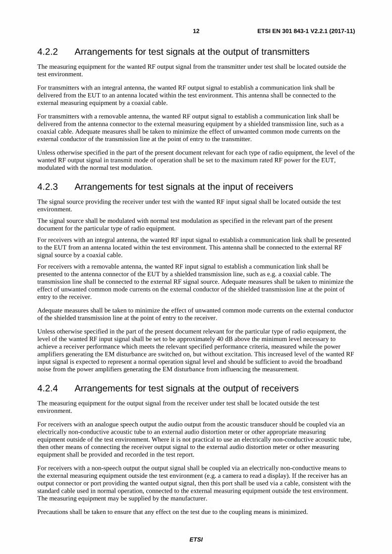
4.2.2 Arrangements for test signals at the output of transmitters
The measuring equipment for the wanted RF output signal from the transmitter under test shall be located outside the test environment.
For transmitters with an integral antenna, the wanted RF output signal to establish a communication link shall be delivered from the EUT to an antenna located within the test environment. This antenna shall be connected to the external measuring equipment by a coaxial cable.
For transmitters with a removable antenna, the wanted RF output signal to establish a communication link shall be delivered from the antenna connector to the external measuring equipment by a shielded transmission line, such as a coaxial cable. Adequate measures shall be taken to minimize the effect of unwanted common mode currents on the external conductor of the transmission line at the point of entry to the transmitter.
Unless otherwise specified in the part of the present document relevant for each type of radio equipment, the level of the wanted RF output signal in transmit mode of operation shall be set to the maximum rated RF power for the EUT, modulated with the normal test modulation.
4.2.3 Arrangements for test signals at the input of receivers
The signal source providing the receiver under test with the wanted RF input signal shall be located outside the test environment.
The signal source shall be modulated with normal test modulation as specified in the relevant part of the present document for the particular type of radio equipment.
For receivers with an integral antenna, the wanted RF input signal to establish a communication link shall be presented to the EUT from an antenna located within the test environment. This antenna shall be connected to the external RF signal source by a coaxial cable.
For receivers with a removable antenna, the wanted RF input signal to establish a communication link shall be presented to the antenna connector of the EUT by a shielded transmission line, such as e.g. a coaxial cable. The transmission line shall be connected to the external RF signal source. Adequate measures shall be taken to minimize the effect of unwanted common mode currents on the external conductor of the shielded transmission line at the point of entry to the receiver.
Adequate measures shall be taken to minimize the effect of unwanted common mode currents on the external conductor of the shielded transmission line at the point of entry to the receiver.
Unless otherwise specified in the part of the present document relevant for the particular type of radio equipment, the level of the wanted RF input signal shall be set to be approximately 40 dB above the minimum level necessary to achieve a receiver performance which meets the relevant specified performance criteria, measured while the power amplifiers generating the EM disturbance are switched on, but without excitation. This increased level of the wanted RF input signal is expected to represent a normal operation signal level and should be sufficient to avoid the broadband noise from the power amplifiers generating the EM disturbance from influencing the measurement.
4.2.4 Arrangements for test signals at the output of receivers
The measuring equipment for the output signal from the receiver under test shall be located outside the test environment.
For receivers with an analogue speech output the audio output from the acoustic transducer should be coupled via an electrically non-conductive acoustic tube to an external audio distortion meter or other appropriate measuring equipment outside of the test environment. Where it is not practical to use an electrically non-conductive acoustic tube, then other means of connecting the receiver output signal to the external audio distortion meter or other measuring equipment shall be provided and recorded in the test report.
For receivers with a non-speech output the output signal shall be coupled via an electrically non-conductive means to the external measuring equipment outside the test environment (e.g. a camera to read a display). If the receiver has an output connector or port providing the wanted output signal, then this port shall be used via a cable, consistent with the standard cable used in normal operation, connected to the external measuring equipment outside the test environment. The measuring equipment may be supplied by the manufacturer.
Precautions shall be taken to ensure that any effect on the test due to the coupling means is minimized.
ETSI
ETSI EN 301 843-1 V2.2.1 (2017-11) 13
4.2.5 Arrangements for testing transmitter and receiver together (as a system)
Transmitters and receivers may be tested for immunity as a system when combined as a transceiver or the combined equipment is of a size which allows simultaneous testing. In this case the transceiver or transmitter and receiver shall be located inside the test environment and shall be exposed simultaneously to the immunity test signals.
The normal test modulation shall be transmitted by the test system and looped back in the EUT. Further, the output of the EUT shall be monitored by the test system.
For combined testing of transceivers or transmitters and receivers operating at the same frequency, two samples of the EUT are required. The wanted RF output signal of the transmitter (sample A) may be used via a suitable attenuator and applied to the input of the receiver (sample B) as the wanted RF input signal.
For transceivers or transmitters and receivers operating at different frequencies e.g. in duplex mode the arrangements are defined in the product related part of the present document for the particular type of radio equipment.
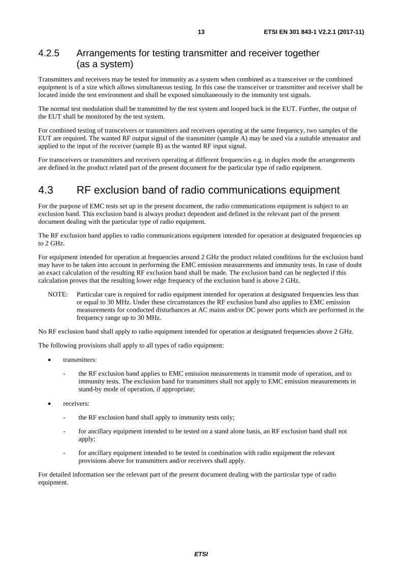
4.3 RF exclusion band of radio communications equipment For the purpose of EMC tests set up in the present document, the radio communications equipment is subject to an exclusion band. This exclusion band is always product dependent and defined in the relevant part of the present document dealing with the particular type of radio equipment.
The RF exclusion band applies to radio communications equipment intended for operation at designated frequencies up to 2 GHz.
For equipment intended for operation at frequencies around 2 GHz the product related conditions for the exclusion band may have to be taken into account in performing the EMC emission measurements and immunity tests. In case of doubt an exact calculation of the resulting RF exclusion band shall be made. The exclusion band can be neglected if this calculation proves that the resulting lower edge frequency of the exclusion band is above 2 GHz.
NOTE: Particular care is required for radio equipment intended for operation at designated frequencies less than or equal to 30 MHz. Under these circumstances the RF exclusion band also applies to EMC emission measurements for conducted disturbances at AC mains and/or DC power ports which are performed in the frequency range up to 30 MHz.
No RF exclusion band shall apply to radio equipment intended for operation at designated frequencies above 2 GHz.
The following provisions shall apply to all types of radio equipment:
• transmitters:
- the RF exclusion band applies to EMC emission measurements in transmit mode of operation, and to immunity tests. The exclusion band for transmitters shall not apply to EMC emission measurements in stand-by mode of operation, if appropriate;
• receivers:
- the RF exclusion band shall apply to immunity tests only;
- for ancillary equipment intended to be tested on a stand alone basis, an RF exclusion band shall not apply;
- for ancillary equipment intended to be tested in combination with radio equipment the relevant provisions above for transmitters and/or receivers shall apply.
For detailed information see the relevant part of the present document dealing with the particular type of radio equipment.
ETSI
ETSI EN 301 843-1 V2.2.1 (2017-11) 14
4.4 Narrow band responses of receivers or receivers which are part of transceivers
Responses on receivers or the receiver part of (duplex) transceivers occurring during the immunity tests at discrete frequencies which are narrow band responses (spurious responses), are identified by the following method:
• If during the test the immunity RF test signal (see clauses 9.2 and 9.5) causes non-compliance of the receiver with the specified performance criteria for continuous phenomena (see clause 6.1), it is necessary to establish whether this non compliance is due to a narrow band response or a wideband phenomenon. Therefore, the frequency of the test signal is increased by an amount equal to twice the nominal 6 dB bandwidth of the filter immediately preceding the demodulator of the receiver, or if appropriate, the bandwidth over which the apparatus is intended to operate, as declared by the manufacturer. The test is repeated with the frequency of the test signal decreased by the same amount.
• If the receiver is then in either or both frequency offset cases in compliance with the specified performance criteria, the response is considered as a narrow band response.
• If the receiver still does not comply with the specified performance criteria, this may be due to the fact that the offset has made the frequency of the unwanted signal correspond to the frequency of another narrow band response. Under these circumstances the procedure is repeated with an increase and decrease of the frequency of the test signal adjusted two and a half times the bandwidth referred to above.
• If the receiver still does not comply with the specified performance criteria in either or both frequency offset cases, the phenomena is considered wideband and therefore an EMC problem and the equipment fails the test.
For immunity tests, narrow band responses shall be disregarded.
Particular performance criteria typical for the relevant type of EUT and information about any product type dependent nominal frequency offset to be used for the identification of narrowband responses are always specified in clause 4.4 Narrow band responses on receivers - of the part of the present multi-part deliverable dealing with each type of radio equipment.
Where narrow band responses of receivers are not permitted, this shall be stated within the part of the present document dealing with particular type of radio equipment.
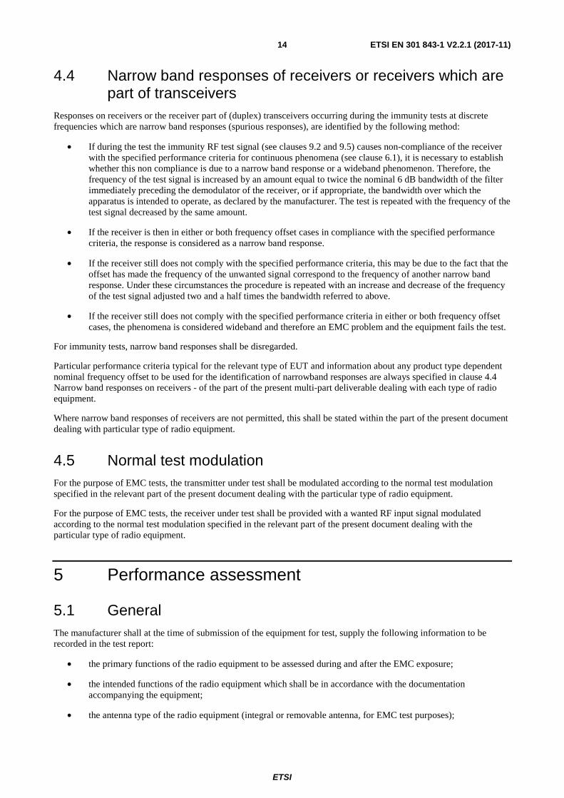
4.5 Normal test modulation For the purpose of EMC tests, the transmitter under test shall be modulated according to the normal test modulation specified in the relevant part of the present document dealing with the particular type of radio equipment.
For the purpose of EMC tests, the receiver under test shall be provided with a wanted RF input signal modulated according to the normal test modulation specified in the relevant part of the present document dealing with the particular type of radio equipment.
5 Performance assessment
5.1 General The manufacturer shall at the time of submission of the equipment for test, supply the following information to be recorded in the test report:
• the primary functions of the radio equipment to be assessed during and after the EMC exposure;
• the intended functions of the radio equipment which shall be in accordance with the documentation accompanying the equipment;
• the antenna type of the radio equipment (integral or removable antenna, for EMC test purposes);
ETSI
ETSI EN 301 843-1 V2.2.1 (2017-11) 15
• the user control functions and stored data that are required for normal operation and the method to be used to assess whether these have been lost after the EMC exposure;
• the type of modulation, the characteristics of the transmission used for testing (random bit stream, message format, etc.) and the necessary test equipment delivered to enable the assessment of the EUT;
• the maximum rated RF output power of transmitters, if appropriate;
• the ancillary equipment to be combined with the radio equipment for testing (where applicable);
• the ancillary equipment intended to be tested on a stand alone basis (where applicable);
• an exhaustive list of ports, with the maximum cable lengths allowed, classified as either power or telecommunication/signal/control. Power ports shall further be classified as AC or DC power;
• the bandwidth of the filter immediately preceding the demodulator;
• the method to be used to verify that a communication link is established and maintained (if appropriate);
• the operating frequency bands over which the equipment is intended to operate;
• the environment(s) in which the equipment is intended to be used. This declaration shall be as indicated in the user instructions.
If additional product related information is required, these can be found in the relevant part of the present document dealing with the particular type of radio equipment.
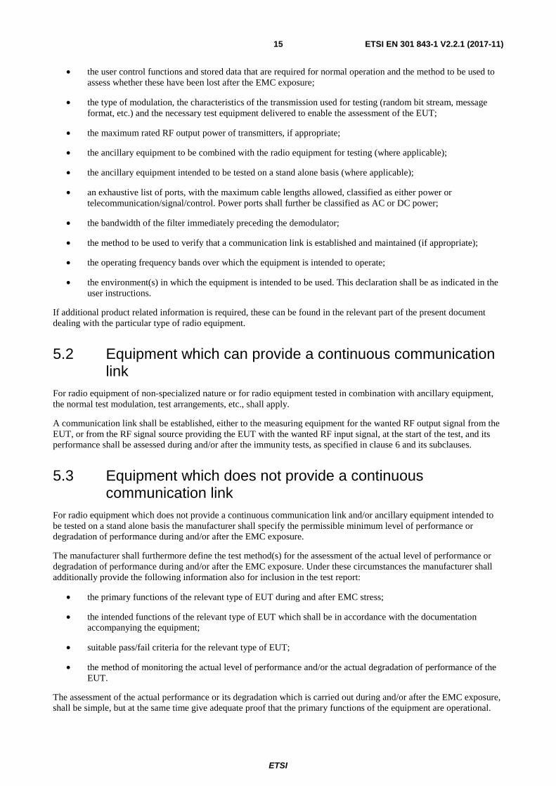
5.2 Equipment which can provide a continuous communication link
For radio equipment of non-specialized nature or for radio equipment tested in combination with ancillary equipment, the normal test modulation, test arrangements, etc., shall apply.
A communication link shall be established, either to the measuring equipment for the wanted RF output signal from the EUT, or from the RF signal source providing the EUT with the wanted RF input signal, at the start of the test, and its performance shall be assessed during and/or after the immunity tests, as specified in clause 6 and its subclauses.
5.3 Equipment which does not provide a continuous communication link
For radio equipment which does not provide a continuous communication link and/or ancillary equipment intended to be tested on a stand alone basis the manufacturer shall specify the permissible minimum level of performance or degradation of performance during and/or after the EMC exposure.
The manufacturer shall furthermore define the test method(s) for the assessment of the actual level of performance or degradation of performance during and/or after the EMC exposure. Under these circumstances the manufacturer shall additionally provide the following information also for inclusion in the test report:
• the primary functions of the relevant type of EUT during and after EMC stress;
• the intended functions of the relevant type of EUT which shall be in accordance with the documentation accompanying the equipment;
• suitable pass/fail criteria for the relevant type of EUT;
• the method of monitoring the actual level of performance and/or the actual degradation of performance of the EUT.
The assessment of the actual performance or its degradation which is carried out during and/or after the EMC exposure, shall be simple, but at the same time give adequate proof that the primary functions of the equipment are operational.
ETSI
ETSI EN 301 843-1 V2.2.1 (2017-11) 16
For radio equipment of a specialized nature, a communication link shall be established, either to the measuring equipment for the wanted RF output signal from the EUT or from the RF signal source providing the EUT with the wanted RF input signal, at the start of the test. Subsequently, customer related information (e.g. packet data) shall be transmitted to load the memory of the receiver under test or measuring equipment with data suitable for the performance assessment during and/or after the test.
These products related performance criteria for a dedicated type of marine radio equipment are always specified in clause 5.3 of the part of the present multi-part deliverable dealing with each type of radio equipment.
5.4 Ancillary equipment At the manufacturer's discretion ancillary equipment may be tested and assessed:
• applying the provisions of the present document:
- separately to the ancillary equipment; or
- to the combination of ancillary and radio equipment; or
• applying another appropriate Harmonised EMC Standard.
In each case, compliance enables the ancillary equipment to be used with different receivers, transmitters or transceivers.
For immunity tests of ancillary equipment tested on a stand alone basis the manufacturer shall specify the permissible minimum level of performance or the permissible degradation of performance during and/or after the EMC exposure. The related specifications set out in clause 5.3 have also to be taken into account.
For immunity tests of ancillary equipment tested in combination with the radio equipment and not having separate pass/fail criteria, the receiver, transmitter or transceiver coupled to the ancillary equipment shall be used to judge whether the ancillary equipment passes or fails the test.
5.5 Equipment classification For the purpose of the EMC performance assessment in the present document, the marine radio equipment and/or associated ancillary equipment under test shall be classified into one of the following two classes:
• mobile equipment; or
• portable equipment;
taking into account the definitions in clause 3.1 of the present document.
This classification determines the extend of applicable EMC tests. However, the following instructions shall also apply to multiple use marine radio and/or ancillary equipment intended for use as portable and mobile equipment:
• portable marine radio and/or ancillary equipment or combinations thereof declared as capable of being powered for intended use by the internal AC or DC mains supply onboard ships shall additionally be considered as mobile equipment.
Subsequently, for multiple use marine radio and/or ancillary equipment both sets of equipment test requirements listed in the tables 1 and 2 of clause 7 of the present document have to be taken into account.

ETSI
ETSI EN 301 843-1 V2.2.1 (2017-11) 17
6 Performance criteria
6.0 General requirements The performance criteria are used to take a decision on whether a radio equipment passes or fails immunity tests.
The establishment of the communication link at the start of the test, its maintenance and the assessment of the recovered signal are used as performance criteria for the evaluation of the essential functions of the radio equipment during and after the test.
Portable marine equipment powered by the internal AC mains supply onboard ships shall in addition fulfil the applicable requirements specified in the present document for mobile equipment.
For the purpose of the present document three categories of performance criteria apply:
• performance criteria A for continuous phenomena applied to transmitters and receivers;
• performance criteria B for transient phenomena applied to transmitters and receivers; and
• performance criteria C applied to power supply failure.
Normally, the performance criteria depend on the type of radio equipment. Thus, the present document only contains general performance criteria commonly used for the assessment of radio equipment. More specific and product related performance criteria for a dedicated type of radio equipment may be found in the part of the present document dealing with the particular type of the radio equipment.
6.1 Performance criteria A for continuous phenomena applied to transmitters and receivers
If no further details are given in the relevant part of the present document dealing with the particular type of radio equipment, the following general performance criteria A for continuous phenomena shall apply.
During and after the test, the apparatus shall continue to operate as intended. No degradation of performance or loss of function is allowed below a permissible performance level as defined in the immunity performance check, or as specified by the manufacturer for the intended use. In some cases this permissible performance level may be replaced by a permissible loss of performance.
During the test the EUT shall not unintentionally transmit or change its actual operating state and stored data.
If the minimum performance level or the permissible performance loss is not specified by the manufacturer, then either of these may be deduced from the product description and documentation and what the user may reasonably expect from the apparatus if used as intended.
The EUT shall be subjected to the performance check (see clause 6.4) during and after the test. The EUT shall meet the requirements of the performance check.
6.2 Performance criteria B for transient phenomena applied to transmitters and receivers
If no further details are given in the relevant part of the present multi-part deliverable dealing with the particular type of radio equipment, the following general performance criteria B for transient phenomena shall apply.
After the test, the apparatus shall continue to operate as intended. No degradation of performance or loss of function is allowed below a permissible performance level as defined in the immunity performance check, or as specified by the manufacturer for the intended use. In some cases this permissible performance level may be replaced by a permissible loss of performance.
During the EMC exposure to an electromagnetic phenomenon, a degradation of performance is, however, allowed. No change of the actual mode of operation (e.g. unintended transmission) or stored data is allowed.
ETSI
ETSI EN 301 843-1 V2.2.1 (2017-11) 18
If the minimum performance level or the permissible performance loss is not specified by the manufacturer, then either of these may be deduced from the product description and documentation and what the user may reasonably expect from the apparatus if used as intended.
The EUT shall be subjected to the performance check (see clause 6.4) after the test. The EUT shall meet the requirements of the performance check.
6.3 Performance criteria C applied to power supply failure During the test sequence the EUT shall not unintentionally transmit or change stored data.
Temporary degradation or loss of function or performance is allowed during the test sequence, provided the function, as defined by the immunity performance assessment procedure and in the technical specification published by the manufacturer, is self recoverable or can be restored after the test by operation of user controls.
The EUT shall be subjected to the performance check (see clause 6.4) after the test. The EUT shall meet the requirements of the performance check.
6.4 Performance check The performance check for marine radio equipment shall be used to verify whether the EUT passes or fails the related immunity test(s). The performance criteria to be used depend on the relevant type of marine radio equipment. These products related performance criteria for a dedicated type of marine radio equipment are always specified in clause 6.4 Performance check - of the part of the present multi-part deliverable dealing with each type of radio equipment.
6.5 Performance criteria for equipment which does not provide a continuous communication link
If the radio equipment does not provide a continuous communication link and the performance criteria described in the clauses above are not appropriate, then the manufacturer shall declare, for inclusion in the test report, his own specification for an acceptable level of performance or degradation of performance during and/or after the immunity tests. The performance specification shall be included in the product description and documentation. The related specifications set out in clause 5.3 have also to be taken into account.
The performance criteria specified by the manufacturer shall give the same degree of immunity protection as called for in the foregoing clauses.
6.6 Performance criteria for ancillary equipment tested on a stand alone basis
If ancillary equipment is intended to be tested on a stand alone basis and the performance criteria described in the clauses above are not appropriate, then the manufacturer shall declare, for inclusion in the test report, his own specification for an acceptable level of performance or degradation of performance during and/or after the immunity tests. The performance specification shall be included in the product description and documentation. The related specifications set out in clause 5.3 have also to be taken into account.
The performance criteria specified by the manufacturer shall give the same degree of immunity protection as called for in the foregoing clauses.

ETSI
ETSI EN 301 843-1 V2.2.1 (2017-11) 19
7 Applicability overview tables
7.0 General The applicability overview tables below give a comprehensive overview about all EMC tests specified in the present document for marine radio and/or associated ancillary equipment.
The applicability of EMC tests specified in the present document depends on the actual type of marine radio and/or associated ancillary equipment under test. All tests are port-related EMC tests. For a certain type of EUT not having a particular type of port or for operational/technical reasons, the related EMC tests do not apply. In these cases, clause 7 of the part of the present document dealing with the particular type of radio equipment provides specifications or restrictions to the applicability of the EMC tests for the actual type of EUT.
7.1 EMC emission
Table 1: EMC emission measurements for marine radio and associated ancillary equipment specified in the present document, overview
Phenomenon Application Equipment test requirement Reference
mobile equipment portable equipment clause in the present document
Radiated emission
Enclosure of ancillary equipment
applicable for stand alone testing
applicable for stand alone testing
8.2
Radiated emission
Enclosure of combinations of radio
and ancillary equipment
not applicable (see note 1)
not applicable (see note 1)
---
Conducted emission
DC power input/output port
applicable not applicable (see note 2)
8.3
Conducted emission
AC mains power input/output port
applicable not applicable (see note 2)
8.4
NOTE 1: The measurement of radiated emissions (enclosure or cabinet radiation) from radio and/or combinations of radio and ancillary equipment is subject to functional radio tests.
NOTE 2: The measurement of conducted EMC emissions is not possible because portable equipment is intended to be powered by its internal batteries only (see also clause 3.1).
7.2 Immunity
Table 2: Immunity tests for marine radio and associated ancillary equipment specified in the present document, overview
Phenomena Application Equipment test requirement Reference
mobile equipment
portable equipment
clause in the present document
RF electromagnetic field (80 MHz to 2 700 MHz)
Enclosure applicable applicable 9.2
Electrostatic discharge Enclosure applicable applicable 9.3 Fast transients common mode Signal and control ports,
DC and AC power ports applicable not applicable 9.4
RF common mode (0,15 MHz to 80 MHz)
Signal and control ports, DC and AC power ports
applicable not applicable 9.5
Short term power supply variations AC power input ports applicable not applicable 9.6.1 Power supply failure AC power input ports applicable not applicable 9.6.2
Surges, line to line and line to ground
AC power input ports applicable not applicable 9.7

ETSI
ETSI EN 301 843-1 V2.2.1 (2017-11) 20
8 Testing for compliance with technical requirements
8.0 Environmental conditions for testing Tests defined in the present document shall be carried out at representative points within the boundary limits of the declared operational environmental profile.
Where technical performance varies subject to environmental conditions, tests shall be carried out under a sufficient variety of environmental conditions (within the boundary limits of the declared operational environmental profile) to give confidence of compliance for the affected technical requirements.
8.1 Test configuration This clause defines the requirements for test configurations:
• the measurements shall be carried out at a point within the specified normal operating environmental range and at the rated supply voltage for the equipment;
• the measurements shall be made in the operational mode producing the largest emission in the frequency band being investigated consistent with normal applications;
• the equipment shall be configured in a manner which is representative for normal/typical operation, where practical;
• an attempt shall be made to maximize the detected radiated emission, e.g. by moving the cables of the equipment;
• where radio equipment is provided with a detachable antenna, it shall be tested with the antenna fitted in a manner typical of normal intended use, unless declared as a removable antenna;
• if the equipment is part of a system, or can be connected to ancillary equipment, then it shall be acceptable to test the equipment while connected to the minimum representative configuration of ancillary equipment necessary to exercise the ports;
• if the equipment has a large number of ports, then a sufficient number shall be selected to simulate actual operational conditions and to ensure that all the different types of termination are covered;
• ports which in normal operation are connected shall be connected to an ancillary equipment or to a representative piece of cable terminated to simulate the impedance of the ancillary equipment. RF input/output ports shall be correctly terminated;
• the configuration and mode of operation during the measurements shall be precisely noted in the test report.
8.2 Enclosure of ancillary equipment measured on a stand alone basis
8.2.0 Applicability
This test shall only be applicable to ancillary equipment not incorporated in the radio equipment and measured on a stand alone basis, as declared by the manufacturer. This test shall be performed on a representative configuration of the ancillary equipment.
This test is not applicable to ancillary equipment incorporated in the radio equipment, or for ancillary equipment measured in combination with the radio equipment. In these cases the requirements of the relevant product standard for the effective use of the radio spectrum shall apply (see clause 1).
ETSI
ETSI EN 301 843-1 V2.2.1 (2017-11) 21
8.2.1 Test description
This test assesses the ability of the ancillary equipment to limit its internal noise from being radiated from the enclosure.
8.2.2 Test method
The test method shall be in accordance with IEC EN 60945 [1].
The ancillary equipment shall be tested under operational conditions typical for its normal use. If these conditions cannot be achieved without connection to the radio equipment, then the ancillary equipment shall be tested in combination with the radio equipment to the related requirements for the enclosure radiation in the relevant radio product standard for the effective use of the radio spectrum.
The EUT shall be placed on a non-conductive support with a height of 1,5 m. The measuring distance between the centre of the test antenna and the EUT shall be as indicated in table 4. A test site in accordance with IEC EN 60945 [1] and CISPR 16-1-1 [2] shall be used.
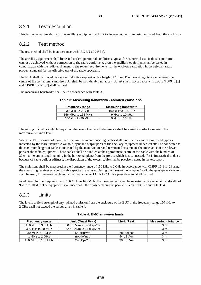
The measuring bandwidth shall be in accordance with table 3.
Table 3: Measuring bandwidth - radiated emissions
Frequency range Measuring bandwidth 30 MHz to 2 GHz 100 kHz to 120 kHz
156 MHz to 165 MHz 9 kHz to 10 kHz 150 kHz to 30 MHz 9 kHz to 10 kHz
The setting of controls which may affect the level of radiated interference shall be varied in order to ascertain the maximum emission level.
When the EUT consists of more than one unit the interconnecting cables shall have the maximum length and type as indicated by the manufacturer. Available input and output ports of the ancillary equipment under test shall be connected to the maximum length of cable as indicated by the manufacturer and terminated to simulate the impedance of the relevant ports of the radio equipment. These cables shall be bundled at the approximate centre of the cable with the bundles of 30 cm to 40 cm in length running in the horizontal plane from the port to which it is connected. If it is impractical to do so because of cable bulk or stiffness, the disposition of the excess cable shall be precisely noted in the test report.
The emissions shall be measured in the frequency range of 150 kHz to 2 GHz in accordance with CISPR 16-1-1 [2] using the measuring receiver or a comparable spectrum analyser. During the measurements up to 1 GHz the quasi-peak detector shall be used, for measurements in the frequency range 1 GHz to 2 GHz a peak detector shall be used.
In addition, for the frequency band 156 MHz to 165 MHz, the measurement shall be repeated with a receiver bandwidth of 9 kHz to 10 kHz. The equipment shall meet both, the quasi peak and the peak emission limits set out in table 4.
8.2.3 Limits
The levels of field strength of any radiated emission from the enclosure of the EUT in the frequency range 150 kHz to 2 GHz shall not exceed the values given in table 4.
Table 4: EMC emission limits
Frequency range Limit (Quasi Peak) Limit (Peak) Measuring distance 150 kHz to 300 kHz 80 dBµV/m to 52 dBµV/m 3 m 300 kHz to 30 MHz 52 dBµV/m to 34 dBµV/m 3 m 30 MHz to 1 GHz 54 dBµV/m not defined 3 m 1 GHz to 2 GHz not defined 54 dBuV/m 3 m
156 MHz to 165 MHz 24 dBµV/m 30 dBµV/m 3 m

ETSI
ETSI EN 301 843-1 V2.2.1 (2017-11) 22
8.3 DC power input/output ports
8.3.0 Applicability
This test shall be applicable to mobile marine radio and ancillary equipment for use onboard ships and intended to be powered by the ship's internal AC or DC mains.
This test is applicable to equipment which may have DC cables longer than 3 m, as declared by the manufacturer.
If the DC power cable of the radio and/or the ancillary equipment is intended to be less than or equal to 3 m in length, and intended only for direct connection to a dedicated AC to DC power supply, then the measurement may be performed on the AC power input of that power supply only.
This test shall be performed on a representative configuration of the radio equipment or a representative configuration of the combination of radio and ancillary equipment.
8.3.1 Test description
This test assesses the ability of transmitters, receivers, transceivers and ancillary equipment to limit internal noise from the DC power input/output ports.
8.3.2 Test method
The test method shall be in accordance with IEC EN 60945 [1] except where noted in this clause.
This test shall be performed on a representative configuration of the EUT in both, the receive and the transmit mode of operation, as appropriate.
The power input cable(s) between DC input ports of the EUT and the Artificial Mains Network (AMN) shall be screened and not exceed 0,8 m in length.
If the EUT consists of more than one unit with individual DC power input ports, power input ports of identical nominal supply voltages shall be connected in parallel to the artificial mains network.
The setting of controls which may affect the level of conducted interference shall be varied in order to ascertain the maximum emission level.
The measuring bandwidth shall be:
• 200 Hz in the frequency range 10 kHz to 150 kHz; and
• 9 kHz to 10 kHz in the frequency range 150 kHz to 30 MHz.
The measurement frequency range extends from 10 kHz to 30 MHz. When the EUT is a transmitter operating at frequencies below 30 MHz, then the exclusion band for transmitters applies (see clause 4.3) for measurements in the transmit mode of operation.
ETSI
ETSI EN 301 843-1 V2.2.1 (2017-11) 23
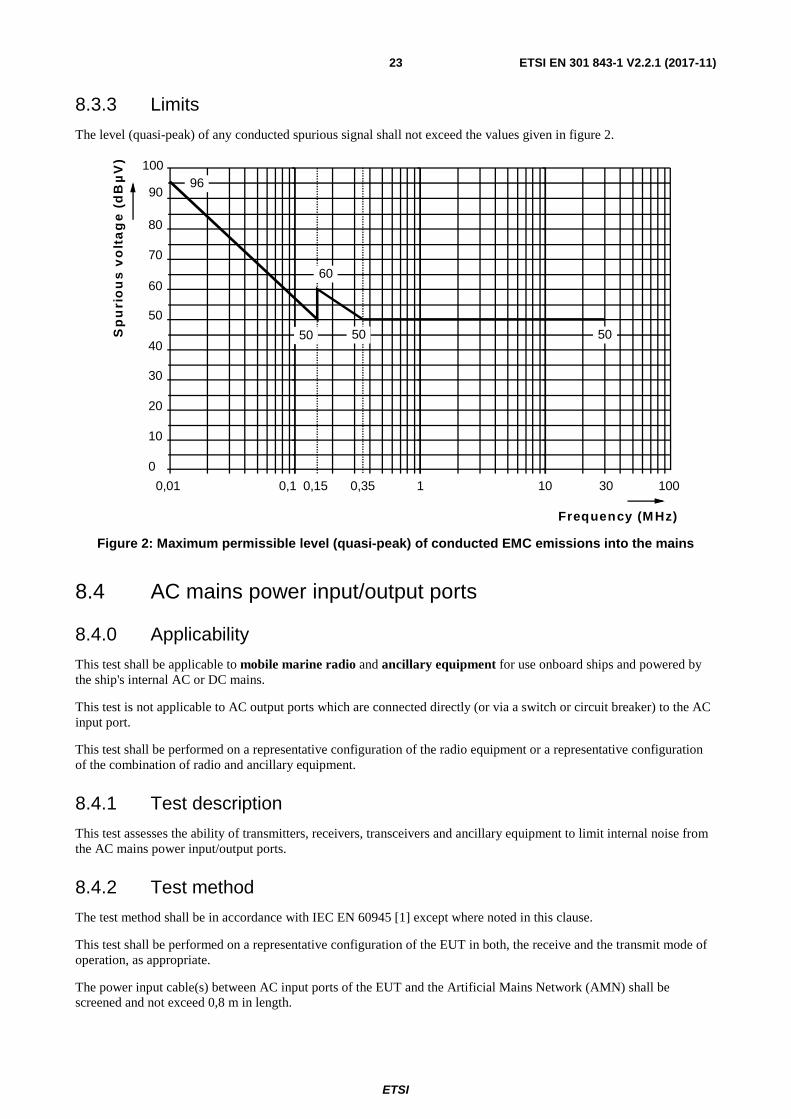
8.3.3 Limits
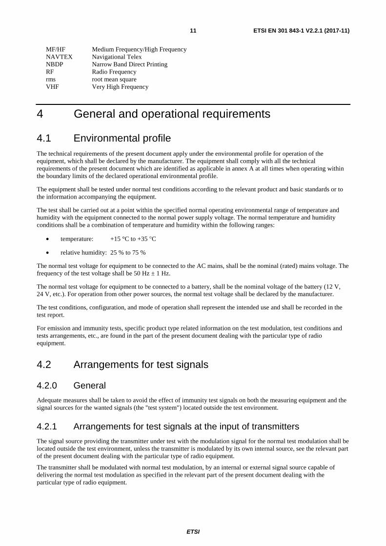
The level (quasi-peak) of any conducted spurious signal shall not exceed the values given in figure 2.
Figure 2: Maximum permissible level (quasi-peak) of conducted EMC emissions into the mains
8.4 AC mains power input/output ports
8.4.0 Applicability
This test shall be applicable to mobile marine radio and ancillary equipment for use onboard ships and powered by the ship's internal AC or DC mains.
This test is not applicable to AC output ports which are connected directly (or via a switch or circuit breaker) to the AC input port.
This test shall be performed on a representative configuration of the radio equipment or a representative configuration of the combination of radio and ancillary equipment.
8.4.1 Test description
This test assesses the ability of transmitters, receivers, transceivers and ancillary equipment to limit internal noise from the AC mains power input/output ports.
8.4.2 Test method
The test method shall be in accordance with IEC EN 60945 [1] except where noted in this clause.
This test shall be performed on a representative configuration of the EUT in both, the receive and the transmit mode of operation, as appropriate.
The power input cable(s) between AC input ports of the EUT and the Artificial Mains Network (AMN) shall be screened and not exceed 0,8 m in length.
0
10
20
30
40
50
60
70
80
Sp
uri
ou
s v
olt
ag
e (
dB
µV
)
Frequency (M Hz)
0,01 0,1 10 300,15 0,35 1 100
90
10096
50
60
50 50
ETSI
ETSI EN 301 843-1 V2.2.1 (2017-11) 24
If the EUT consists of more than one unit with individual AC power input ports, power input ports of identical nominal supply voltages shall be connected in parallel to the artificial mains network.
The setting of controls which may affect the level of conducted interference shall be varied in order to ascertain the maximum emission level.
The measuring bandwidth shall be:
• 200 Hz in the frequency range 10 kHz to 150 kHz; and
• 9 kHz to 10 kHz in the frequency range 150 kHz to 30 MHz.
The measurement frequency range extends from 10 kHz to 30 MHz. When the EUT is a transmitter operating at frequencies below 30 MHz, then the exclusion band for transmitters applies (see clause 4.3) for measurements in the transmit mode of operation.
8.4.3 Limits
The level (quasi-peak) of any conducted spurious signal shall not exceed the values given in figure 2.
9 Test methods and levels for immunity tests
9.0 General For the immunity tests of transmitters, the transmitter shall be operated at its maximum rated RF output power, modulated with normal test modulation (see clause 4.5).
For the immunity tests of receivers, the wanted RF input signal, coupled to the receiver, shall be modulated with normal test modulation (see clause 4.5).
The tests shall be performed in both receive and transmit mode of operation unless otherwise indicated. During the tests with continuous EMC phenomena (conducted and radiated RF immunity tests) the exclusion band for receivers and/or transmitters shall apply (see clause 4.3).
9.1 Test configuration This clause defines the requirements for test configurations:
• the tests shall be carried out at a point within the specified normal operating environmental range and at the rated supply voltage for the equipment;
• if the equipment is part of a system, or can be connected to ancillary equipment, then it shall be acceptable to test the equipment connected to the minimum representative configuration of ancillary equipment necessary to exercise the ports;
• where radio equipment is provided with a detachable antenna, it shall be tested with the antenna fitted in a manner typical of intended use, unless declared as a removable antenna;
• for the immunity tests of ancillary equipment without a separate pass/fail criteria, the receiver or transmitter coupled to the ancillary equipment, shall be used to judge whether the ancillary equipment passes or fails;
• if the equipment has a large number of ports, then a sufficient number shall be selected to simulate actual operational conditions and to ensure that all the different types of termination are covered;
• ports which in normal operation are connected, shall be connected to an ancillary equipment or to a representative piece of cable terminated to simulate the impedance of the ancillary equipment. RF input/output ports shall be correctly terminated;
ETSI
ETSI EN 301 843-1 V2.2.1 (2017-11) 25
• ports which are not connected to cables during normal intended operation, e.g. service connectors, programming connectors, temporary connectors etc. shall not be connected to any cables for the purpose of EMC testing. Where cables have to be connected to these ports, or interconnecting cables have to be extended in length in order to exercise the Equipment Under Test (EUT), precautions shall be taken to ensure that the evaluation of the EUT is not affected by the addition or extension of these cables;
• the configuration and mode of operation during the tests shall be precisely noted in the test report.
9.2 Radio frequency electromagnetic field (80 MHz to 2 700 MHz)
9.2.0 Applicability
This test shall be applicable to mobile and portable marine radio equipment and associated ancillary equipment.
This test shall be performed on a representative configuration of the radio equipment, the associated ancillary equipment, or a representative configuration of the combination of radio and ancillary equipment.
9.2.1 Test description
This test assesses the ability of the EUT to operate as intended in the presence of a radio frequency electromagnetic field disturbance.
9.2.2 Test method
The test method shall be in accordance with IEC EN 61000-4-3 [4].
The following requirements and evaluation of test results shall apply:
• the test level shall be 10 V/m (measured unmodulated). The test signal shall be amplitude modulated (AM) to a depth of 80 % by a sinusoidal audio signal of 400 Hz;
• the test shall be performed over the frequency range 80 MHz to 2 700 MHz with the exception of the exclusion band for transmitters or with the exception of the exclusion band for receivers and duplex transceivers (see clause 4.3), as appropriate;
• for receivers and transmitters the frequency range shall be swept at a rate in the order of 1,5 × 10⁻³ decades per second for the frequency range 80 to 1 000 MHz and 0,5 × 10⁻³ decades per second for the frequency range 1 GHz to 2,7 GHz. Where RF synthesizers are used for testing, these shall be capable of being programmed with frequency-dependant step-sizes and dwell times. The sweep rate shall be slow enough to allow the detection of any malfunction of the EUT, unless specified otherwise in the part of the present document dealing with the particular type of radio equipment;
• further product related spot frequency tests may be specified in the relevant part of the present document dealing with the particular type of radio equipment;
• the frequencies selected and used during the test shall be recorded in the test report.
9.2.3 Performance criteria
The performance criteria A for continuous phenomena shall apply (see clause 6.1).
The provisions of the performance check for transmitters and/or receivers (see clause 6.4) shall apply during and after the test, as appropriate.
For ancillary equipment the pass/fail criteria supplied by the manufacturer (see clauses 5.3 and 6.5) shall apply, unless the ancillary equipment is tested in connection with a receiver or transmitter in which case the corresponding performance criteria above shall apply.
ETSI
ETSI EN 301 843-1 V2.2.1 (2017-11) 26
Responses on receivers occurring at discrete frequencies which are narrow band responses, shall be disregarded from the test (see clause 4.4) unless specified otherwise in the relevant part of the present document for the particular type of radio equipment.
9.3 Electrostatic discharge
9.3.0 Applicability
This test shall be applicable to mobile and portable marine radio equipment and associated ancillary equipment.
This test shall be performed on a representative configuration of the radio equipment, the associated ancillary equipment, or a representative configuration of the combination of radio and ancillary equipment.
9.3.1 Test description
This test assesses the ability of the EUT to operate as intended in the event of an electrostatic discharge.
9.3.2 Test method
The test method shall be in accordance with IEC EN 61000-4-2 [3].
For radio equipment and ancillary equipment the following requirements and evaluation of test results shall apply.
The test severity level for contact discharge shall be 6 kV and for air discharge 8 kV. All other details, including intermediate test levels, are contained within IEC EN 61000-4-2 [3].
Electrostatic discharges shall be applied to all exposed surfaces of the EUT except where the user documentation specifically indicates a requirement for appropriate protective measures. Care should be taken not to apply these discharges to conductive pins of connectors.
The test shall be performed with ten single discharges applied to each test point. Ten test points shall be chosen on exposed surfaces on any unit of the EUT including where appropriate, knobs and other protrusions or projecting parts accessible to the user in normal operation.
NOTE: Ensure that the EUT is carefully discharged between each ESD exposure.
9.3.3 Performance criteria
The performance criteria B for transient phenomena shall apply (see clause 6.2).
The provisions of the performance check for transmitters and/or receivers (see clause 6.4) shall apply after the test, as appropriate.
For ancillary equipment the pass/failure criteria supplied by the manufacturer (see clauses 5.3 and 6.5) shall apply, unless the ancillary equipment is tested in connection with a receiver or transmitter in which case the corresponding performance criteria above shall apply.
9.4 Fast transients, differential and common mode
9.4.0 Applicability
This test shall be applicable to mobile marine radio equipment and associated ancillary equipment.
This test shall be performed on the AC power ports of the radio equipment and associated ancillary equipment.
This test shall be additionally performed on signal and control ports and DC mains power ports (common mode only), if the cables they are connected to are longer than 3 m.

ETSI
ETSI EN 301 843-1 V2.2.1 (2017-11) 27
Where this test is not carried out on any port because the manufacturer declares that it is not intended to be used with cables longer than 3 m, a list of ports which were not tested for this reason shall be included in the test report.
This test shall be performed on a representative configuration of the radio equipment, the associated ancillary equipment, or a representative configuration of the combination of radio and ancillary equipment.
9.4.1 Test description
This test assesses the ability of the EUT to operate as intended in the event of fast transients present on one of the input/output ports.
9.4.2 Test method
The test method shall be in accordance with IEC EN 61000-4-4 [5].
A test generator complying with clause 6.1.1 of IEC EN 61000-4-4 [5] shall be used. The induction of the interference shall be applied to:
• AC/DC power ports by a coupling/decoupling network complying with clause 6.2 of IEC EN 61000-4-4 [5];
• signal and control ports by a capacitive coupling clamp complying with clause 6.6.3 of IEC EN 61000-4-4 [5].
The test level shall be 2 kV differential mode on AC mains power ports, and 1 kV common mode on DC power ports and signal and control ports. The test voltage shall be applied as a 15 ms burst every 300 ms for the duration of 3 minutes for each positive and negative polarity of the test voltage.
9.4.3 Performance criteria
The performance criteria B for transient phenomena shall apply (see clause 6.2).
The provisions of the performance check for transmitters and/or receivers (see clause 6.4) shall apply after the test, as appropriate.
For ancillary equipment the pass/failure criteria supplied by the manufacturer (see clauses 5.3 and 6.5) shall apply, unless the ancillary equipment is tested in connection with a receiver or transmitter in which case the corresponding performance criteria above shall apply.
9.5 Radio frequency, common mode
9.5.0 Applicability
This test shall be applicable to mobile marine radio equipment and associated ancillary equipment.
This test shall be performed on the AC power input ports of the radio equipment and associated ancillary equipment.
This test shall be additionally performed on signal and control ports and DC power ports of radio equipment and associated ancillary equipment, if the cables they are connected to may be longer than 3 m.
Where this test is not carried out on any port because the manufacturer declares that it is not intended to be used with cables longer than 3 m, a list of ports which were not tested for this reason shall be included in the test report.
This test shall be performed on a representative configuration of the radio equipment, the associated ancillary equipment, or a representative configuration of the combination of radio and ancillary equipment.
9.5.1 Test description
This test assesses the ability of the EUT to operate as intended in the presence of a radio frequency electromagnetic disturbance on the input/output ports.
ETSI
ETSI EN 301 843-1 V2.2.1 (2017-11) 28
9.5.2 Test method
The test method shall be in accordance with IEC EN 61000-4-6 [7].
The following requirements and evaluation of test results shall apply:
• the test signal shall be applied to the AC or DC power supply line by a coupling/decoupling network complying with clause 6.2.2.1 of IEC EN 61000-4-6 [7];
• the test signal shall be applied to signal input/output and control lines by direct injection as described in clause 6.2.1 of IEC EN 61000-4-6 [7];
• the test level shall be severity level 2 as given in IEC EN 61000-4-6 [7] corresponding to 3 V rms unmodulated. The test signal shall then be amplitude modulated (AM) to a depth of 80 % by a sinusoidal audio signal of 400 Hz;
• the test shall be performed over the frequency range 150 kHz to 80 MHz with the exception of an exclusion band for transmitters, for receivers, or duplex transceivers, (see clause 4.3);
• for receivers and transmitters the frequency range shall be swept at a rate not exceeding 1,5 × 10⁻³ decades per second;
• additionally, a test shall be performed with a test level of 10 V rms at the following frequencies:
- 2 MHz, 3 MHz, 4 MHz, 6,2 MHz, 8,2 MHz, 12,2 MHz, 16,5 MHz, 18,8 MHz, 22 MHz and 25 MHz;
• the frequencies of the immunity test signal selected and used during the test shall be recorded in the test report.
9.5.3 Performance criteria
The performance criteria A for continuous phenomena shall apply (see clause 6.1).
The provisions of the performance check for transmitters and/or receivers (see clause 6.4) shall apply during and after the test, as appropriate.
For ancillary equipment the pass/failure criteria supplied by the manufacturer (see clauses 5.3 and 6.5) shall apply, unless the ancillary equipment is tested in connection with a receiver or transmitter in which case the corresponding performance criteria above shall apply.
Responses on receivers occurring at discrete frequencies which are narrow band responses, shall be disregarded from the test (see clause 4.4) unless specified otherwise in the relevant part of the present document for the particular type of radio equipment.
9.6 Power supply variations
9.6.0 Applicability
These tests shall be applicable to mobile marine radio equipment and associated ancillary equipment.
These tests shall be performed on the AC power port of radio equipment and associated ancillary equipment.
These tests shall be performed on a representative configuration of the radio equipment, the associated ancillary equipment, or a representative configuration of the combination of radio and ancillary equipment.
9.6.1 Power supply short term variations
9.6.1.1 Test description
These tests assess the ability of the EUT to operate as intended when being subjected to power supply short term variations present on the AC power input ports.
ETSI
ETSI EN 301 843-1 V2.2.1 (2017-11) 29
9.6.1.2 Test method
The test method shall be in accordance with IEC EN 60945 [1]. The EUT shall be subject to the following power supply variations relative to the nominal value once per minute for the duration of 10 minutes each:
a) test voltage = 1,2 times nominal voltage ±1 %, duration (1,5 ± 0,2) s;
test frequency = 1,1 times nominal frequency ±0,5 %, duration (5 ± 0,5) s, superimposed;
b) test voltage = 0,8 times nominal voltage ±1 %, duration (1,5 ± 0,2) s;
test frequency = 0,9 times nominal frequency ±0,5 %, duration (5 ± 0,5) s, superimposed.
The voltage and frequency variation rise and decay times are (0,2 ± 0,1) s (at 10 % and 90 %).
9.6.1.3 Performance criteria
The performance criteria B for transient phenomena shall apply (see clause 6.2).
The provisions of the performance check for transmitters and/or receivers (see clause 6.4) shall apply after the test, as appropriate.
For ancillary equipment the pass/failure criteria supplied by the manufacturer (see clauses 5.3 and 6.5) shall apply, unless the ancillary equipment is tested in connection with a receiver or transmitter in which case the corresponding performance criteria above shall apply.
9.6.2 Power supply failure
9.6.2.1 Test description
This test assesses the ability of the EUT to operate as intended after being subjected to short breaks in the power supply due to power supply change over and breaker dropout. This test is not applicable to an EUT intended for operation from battery power sources only or fitted with or connected to back-up batteries. It covers the break allowed by the IMO Convention [i.9] for changeover between ships main and emergency power supplies.
9.6.2.2 Test method
The EUT shall be subjected to three breaks in the power supply of a duration of 60 s each.
9.6.2.3 Performance criteria
Performance criterion C, clause 6.3 shall apply.
9.7 Surges
9.7.0 Applicability
This test shall be applicable to mobile marine radio equipment and associated ancillary equipment.
These tests shall be performed on the AC power input port of radio equipment and associated ancillary equipment.
These tests shall be performed on a representative configuration of the radio equipment, the associated ancillary equipment, or a representative configuration of the combination of radio and ancillary equipment.
9.7.1 Test description
These tests assess the ability of the EUT to operate as intended in the event of surges present on the AC power input ports.

ETSI
ETSI EN 301 843-1 V2.2.1 (2017-11) 30
9.7.2 Test method
The test method shall be in accordance with IEC EN 61000-4-5 [6].
A combination wave (hybrid) generator complying with clause 6.1 of IEC EN 61000-4-5 [6] in combination with any coupling/decoupling network complying with clause 6.3 of IEC EN 61000-4-5 [6] shall be used.
The following requirements and evaluation of test results shall apply:
• the test voltage shall be 0,5 kV line-to-line and 1 kV line-to-ground with the output impedance of the surge generator as given in the IEC EN 61000-4-5 [6]. The test voltage shall be applied with a repetition rate of 6 pulses/min for a duration of 3 minutes for each of the positive and negative polarity of the test voltage;
• the test generator shall provide the 1,2/50 μs pulse as defined in IEC EN 61000-4-5 [6].
9.7.3 Performance criteria
The performance criteria B for transient phenomena shall apply (see clause 6.2).
The provisions of the performance check for transmitters and/or receivers (see clause 6.4) shall apply after the test, as appropriate.
For ancillary equipment the pass/failure criteria supplied by the manufacturer (see clauses 5.3 and 6.5) shall apply, unless the ancillary equipment is tested in connection with a receiver or transmitter in which case the corresponding performance criteria above shall apply.
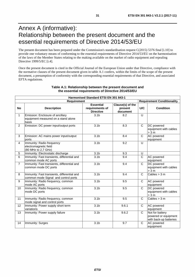
ETSI
ETSI EN 301 843-1 V2.2.1 (2017-11) 31
Annex A (informative): Relationship between the present document and the essential requirements of Directive 2014/53/EU The present document has been prepared under the Commission's standardisation request C(2015) 5376 final [i.10] to provide one voluntary means of conforming to the essential requirements of Directive 2014/53/EU on the harmonisation of the laws of the Member States relating to the making available on the market of radio equipment and repealing Directive 1999/5/EC [i.4].
Once the present document is cited in the Official Journal of the European Union under that Directive, compliance with the normative clauses of the present document given in table A.1 confers, within the limits of the scope of the present document, a presumption of conformity with the corresponding essential requirements of that Directive, and associated EFTA regulations.
Table A.1: Relationship between the present document and the essential requirements of Directive 2014/53/EU
Harmonised Standard ETSI EN 301 843-1 Requirement Requirement Conditionality
No Description Essential
requirements of Directive
Clause(s) of the present
document U/C Condition
1 Emission: Enclosure of ancillary equipment measured on a stand alone basis
3.1b 8.2 U
2 Emission: DC power input/output ports 3.1b 8.3 C DC powered equipment with cables > 3 m
3 Emission: AC mains power input/output ports
3.1b 8.4 C AC powered equipment
4 Immunity: Radio frequency electromagnetic field (80 MHz to 2,7 GHz)
3.1b 9.2 U
5 Immunity: Electrostatic discharge 3.1b 9.3 U 6 Immunity: Fast transients, differential and
common mode AC ports 3.1b 9.4 C AC powered
equipment 7 Immunity: Fast transients, differential and
common mode DC ports 3.1b 9.4 C DC powered
equipment with cables > 3 m
8 Immunity: Fast transients, differential and common mode Signal and control ports
3.1b 9.4 C Cables > 3 m
9 Immunity: Radio frequency, common mode AC ports
3.1b 9.5 C AC powered equipment
10 Immunity: Radio frequency, common mode DC ports
3.1b 9.5 C DC powered equipment with cables > 3 m
11 Immunity: Radio frequency, common mode signal and control ports
3.1b 9.5 C Cables > 3 m
12 Immunity: Power supply short term variations
3.1b 9.6.1 C AC powered equipment
13 Immunity: Power supply failure 3.1b 9.6.2 C Not for battery powered or equipment with back-up batteries
14 Immunity: Surges 3.1b 9.7 C AC powered equipment

ETSI
ETSI EN 301 843-1 V2.2.1 (2017-11) 32
Key to columns:
Requirement:
No A unique identifier for one row of the table which may be used to identify a requirement.
Description A textual reference to the requirement.
Essential requirements of Directive
Identification of article(s) defining the requirement in the Directive.
Clause(s) of the present document
Identification of clause(s) defining the requirement in the present document unless another document is referenced explicitly.
Requirement Conditionality:
U/C Indicates whether the requirement is unconditionally applicable (U) or is conditional upon the manufacturer's claimed functionality of the equipment (C).
Condition Explains the conditions when the requirement is or is not applicable for a requirement which is classified "conditional".
Presumption of conformity stays valid only as long as a reference to the present document is maintained in the list published in the Official Journal of the European Union. Users of the present document should consult frequently the latest list published in the Official Journal of the European Union.
Other Union legislation may be applicable to the product(s) falling within the scope of the present document.

ETSI
ETSI EN 301 843-1 V2.2.1 (2017-11) 33
Annex B (informative): Bibliography
• Directive 2014/30/EU of the European Parliament and of the Council of 26 February 2014 on the harmonisation of the laws of the Member States relating to electromagnetic compatibility.

ETSI
ETSI EN 301 843-1 V2.2.1 (2017-11) 34
Annex C (informative): Change history
Version Information about changes 2.1.1 First version under the Radio Equipment Directive

ETSI
ETSI EN 301 843-1 V2.2.1 (2017-11) 35
History
Document history
V1.1.1 February 2001 Publication
V1.2.1 June 2004 Publication
V1.3.1 August 2012 Publication
V2.1.1 March 2016 Publication
V2.2.0 July 2017 EN Approval Procedure AP 20171017: 2017-07-19 to 2017-10-17
V2.2.1 November 2017 Publication