(en) instruction sol-expert group fileobstacles. escape robot has an in-built microprocessor which...
TRANSCRIPT

SOL-EXPERTgroupgroup
(EN)
INSTRUCTION
Escape Robot
Kit
www.sol-expert-group.dewww.sol-expert-group.de

The Escape Robot Kit works just like an A.I. robot. It never fails to find its way out of a maze. The Escape Robot makes use of three infrared emitting diodes and one infrared receiving module to send and receive signals and detect obstacles. Escape Robot has an in-built microprocessor which enables it to "think" on its own, as it process information about its environment and maneuvers itself around obstacles.Escape Robot moves on six legs. The Kit comes complete with 2 sets of differently designed legs, which provides endless fun and excitement with its different sets of movements.
Power source required:Voltage / Electronical / Mechanical: 1.5V "AAA" x4 batteries ( not included )
Solder WireSoldering Iron
2. Tools You May Need:
1. Product Introduction:
Long Nose Pliers ScrewdriverDiagonal CutterAAA Battery (4pcs)
Electrolytic Capacitor
Value Qty
100uf 1pc
Qty
Housing
1 pc
Qty
Infrared Emitting Diodes 5mm
3 pcs (Clear)
Qty
1 pc
LED 5mm Red
QtyValueID
1 pc
Zener Diode
3.9VID
Qty
IC Socket
1 pc
ID
Qty
Integrated Circuits
I.D.
1 pc 78P156ID
Red Red
Qty
3 pcs
LED Holder
Qty
1 pc
Buzzer
Qty
1pc
Value
Oscillator
4MHz(4.000)
100
1.2K
10
Value Qty
Resistor
brown black black gold
brown red red
red red red
brown black brown
Color
gold
gold
gold
brown black red gold
brown black orange
red red orange
gold
gold
2 pcs
1 pc
5 pcs
1 pc
4 pcs
1K
10K
4 pcs
1 pc 2.2K
22K
QtyValue
Transistor
8550
8050
9013
C945
7 pcs
1 pc
4 pcs
4 pcs
QtyValue
Ceramic Capacitor
2 pcs 30
104
103 1 pc
3 pcs
224 1 pc
(EN) Escape Robot - KitSOL-EXPERTgroupgroup
Keep the adress of the company - Not suitable for children under 3 years. Contains small parts!
0 - 3
!WARNING!
10+
- 13 -

Printed Circuit Board
4. Mechanical Part List:
Qty
P13 Screw
2 pcs (3x6mm)
Qty
Screw
4 pcs (3x6mm)
P14
5. PCB Assembly:
Step 1: diode.
Suggest you start from the low-key components first such as the resistors and zener
Qty
Slide Switch
1 pc
Qty
Pins
4 pcs
Qty
1 pc
Battery Holder
Qty
1 pc Yellow
Connector With Wire
1 pc Green
1 pc Blue
1 pc Orange
Qty
P16 Nut
2 pcs(M3)
Qty
Hex PostP15
2 pcs (10mm)
QtyDescriptionPart I.D. Color Code
brown black brown gold
brown black black gold10
brown red red gold
red red red gold
brown black red gold
4 pcs
5 pcs
1.2K
100
1K
R18
R11 /12 /13 /14
R3 / 4
R1
R5 / 7 / 8 / 9 /10
2 pcs
1 pc
1 pc
Qty
1pc
Infrared Receiving Module
21-8
86
IR_
RX
_M
OD
Qty
P17
1 pc
Body
2 pcs
Qty
P18 Hosepipe
The parts I.D.(identification)for each component has been printed on PCB.
X
2.2K
brown black orange gold
red red orange gold 4 pcs
10K
22K
R15
R2 / 6 /16 /17
1 pc
WIR
EM
OT
OR
WIR
EM
OT
OR
K
K
K
K
21-8
86
ON
OF
F
R18
EC1
C1
C4
R15 R11
R12
R13
R14
R1
R3
R4
R5
R7
R8
R9
R10
R2R6
R16 R17
C2 C3
C5
XTAL
Q5
Q6
Q7
Q8
Q2
BZ1
Q1
Q3
Q4
Q9
Q10
Q11
Q12
Q13Q14
Q15Q16
BA
T.
IC1
LE
D2
LED3
LED4
IR_R
X_M
OD
LED1
SW
M
M2
M
M1
ZD1
WIR
EM
OT
OR
WIR
EM
OT
OR
K
K
K
K
21
-88
6
ON
OF
F
R18
EC1
C1
C4
R15 R11
R12
R13
R14
R1
R3
R4
R5
R7
R8
R9
R10
R2R6
R16 R17
C2 C3
C5
XTAL
Q5
Q6
Q7
Q8
Q2
BZ1
Q1
Q3
Q4
Q9
Q10
Q11
Q12
Q13Q14
Q15Q16
BA
T.
IC1
LE
D2
LED3
LED4
IR_
RX
_M
OD
LED1
SW
M
M2
M
M1
ZD1
- 14 -

Step 2: Electrolytic capacitor, Transistor, Oscillator.
Mount and soldering the components such as Ceramic capacitor,
QtyDescriptionPart I.D.
EC1 Electrolytic Capacitor 100uf 1 pc
Step 3: Buzzer, Pins.
Mount and soldering the components such as IC socket, Housing, Slide switch,
QtyDescriptionPart I.D.
Transistor 8550Q5 / 6 / 7 / 8
Transistor 8050
Transistor C945
Q1 / 3 / 4 / 9 / 10 / 11 / 12
Q2 1 pc
4 pcs
Q13 / 14 / 15 / 16 4 pcs
7 pcs
Transistor 9013
XTAL 1 pc Oscillator 4MHz
Step 4: Mount and soldering LED 5mm red, IR-LED3mm, IC 1602BP.
QtyDescriptionPart I.D.
Zener Diode 3.9V 1 pc ZD1
QtyDescriptionPart I.D.
Ceramic Capacitor 30
Ceramic Capacitor 103
1 pc
C2,C3
C1
2 pcs
C4
C5
Ceramic Capacitor 104
Ceramic Capacitor 224
1 pc
1 pc
QtyDescriptionPart I.D.
4 pcs
BAT.
SW.
M1(+ )
M2(+ )
1 pc
1 pc
1 pc
Slide Switch
Pins
IC 1 IC Socket
Housing
1 pc
BZ1
IC 1
ID
IC Socket ID
1 pc
QtyDescriptionPart I.D.
LED 5mm (red)LED 1 1 pc
IR-LED 5mm (clear)LED 2 / 3 /4 3 pcs
Remark:
PCB
LED Holder
Infrared Emitting Diodes 5mm
78P156
- 15 -

QtyDescriptionPart I.D.
IR_RX_MOD
Step 5: Mount and soldering Infrared Receiving Module.
6. Mechanical Assembly:
1 pc Infrared Receiving Module
Assemble the gearbox first before go ahead for this section.(Refer to the gearbox instruction manual.)
1
2 Toward the shaft of motor to the same way as below drawing to solder wires and ceramic capacitor.
Yellow Wire
Green Wire
10
4
Orange Wire
Blue Wire
10
4
ceramic capacitor 104
Yellow
Green
Orange
Blue
3 Battery Holder Assembly
Finished PCB
P13 x2
P14 x2
P15 x2
Remark:
Bottom Layer
PAD
PCB
PC
B
IR_RX_MOD
21-886
IR_RX_MOD
21-886
IR_RX_MOD
- 16 -

PCB & Gearbox Assembly4
6 Wiring Assembly 7 Finished Product
Yellow
Orange
Green
Blue
Blue Green
Yellow
Orange P5 x4
Note: The yellow and green wires must be at front (toward the same way as infrared emitting diodes).
5 Body & Hosepipe Assembly
Blue
GreenYellow
Orange P17
P14 x2 P18 x2
P16 x2
M1(+) M1(-) M2(+) M2(-)
GreenBlueOrange Yellow
MM
2
+
MM
1
+
Yellow Green
Blue
Orange
- 17 -

-+
-+
R5
1K
R1
2.2K
C2
30
C3
30
ZD1
3.9V
C5
224
XTAL
4MHz
<Front> IR_TXLED2
Q1
8050 VDD
+6V
VDD
78P156(1602BP)
١١
١٦
١٥٥
١٤
١IC
MOD_RX_IR
DC 4.5V_6V.
BATTERY
+6V+4.5V
POWER SW
SW-SPDT
DATA
R7
1K
R3
1.2K
<Right> IR_TXLED4
Q3
8050
+6V
١٠
R8
1K
R4
1.2K
<Left> IR_TXLED3
Q4
8050
+6V
١۲
Fro
nt I
R_T
X
Rig
ht I
R_T
X
Lef
t IR
_TX
BU
ZZ
ER
(B
iBi)
Rig
ht
IR_T
X
DA
TA
Mot
or
CO
N.2
-1
Mot
or
CO
N.1
-2
Fro
nt I
R_
TX
Mot
or
CO
N.2
-2
Mot
or
CO
N.1
-1
Lef
t IR
_T
X
Q5
8550
Q7
8550Q13
C945
Q14
C945
Q9
8050
Q11
8050
R11
10R
R13
10R
A
M2 MOTOR
+4.5VMotor CON.1-2Motor CON.1-1
Q6
8550
Q8
8550Q15
C945
Q16
C945
Q10
8050
Q12
8050
R12
10R
R14
10R
A
M1 MOTOR
+4.5VMotor CON.2-2Motor CON.2-1
٩ ١١ ۸ ١٠ ١٢ ١۸ ١٧ ٢ ١
٩
١۸ ١٧
٢ ١
R15
10K
C1
103
VDD
٤
C4 104
R17
22K
R16
22K
R2
22K
R6
22K
R10
1K
Q2
9013
VDD
۸
BU
ZZ
ER
(B
iBi)
BZ1
BUZZER
R18
100REC1
100uF
VDD
R9
1KLED1
RED
7. How it works:
Switch power to "ON". The LED 1 will light up and the unit will emit 3 beeps as it starts running.
When the unit starts running, the emitting diodes LED2, LED3 and LED4 will send out signals sequentially to detect obstacles along its path. Once an obstacle has been detected, the signal received will be transmitted to the receiving module which will then instruct the Escape Robot to take evasive actions.
a When the emitting diode on the right detects an obstacle, the unit will emit a "beep" sound, and the left motor will go into reverse mode.
b When the emitting diode on the left detects an obstacle, the unit will emit a "beep" sound and the right motor will go into reverse mode.
c When the emitting diode in the middle detects an obstacle, the unit will emit two "beeps" followed by the two motors going into reverse mode. Then, the operation of (a) above is repeated.
d If all three emitting diodes detects obstacles, the unit will emit three "beeps" and the movement that follows will be the same as in ( c ) above. However, the turning will take a little longer.
)
)
)
)
1.
2.
8. Trouble shooting:
Ensure that all components on the PCB are in order. Take note especially of the polarity of the infrared emitting diode.
Different environment and battery power may affect the detecting sensitivity, try to adjust the Infrared Receiving Module's angle to find the best position.
1.
2.
9. Circuit Diagram:
IR_RX_MOD
21-886
- 18 -

SIX-LEG WALKING TYPE GEARBOX - Kit
3. Mechanical Part List:
2. Tools You May Need:
1. Product Introduction:
This gearbox works with 2 types of feet.Try the different feet and enjoy the fun they will bring you
This set contains 2 motors,gears,and all necessary parts
Output speed: 170 RPM
Easy to assembly
●
●
●
●
Qty
P7 Gear(44T+0) with Shaft
(Green)2 pcs
Qty
P8 Gear(44T+0) with Shaft
(Orange)4 pcs
SOL-EXPERTgroupgroup
Keep the adress of the company - Not suitable for children under 3 years. Contains small parts! 0 - 3
!WARNING!
10+
- 19 -
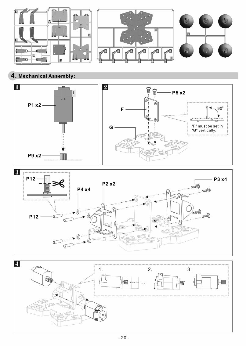
4. Mechanical Assembly:
4
1 2
1. 2. 3.
P1 x2
P9 x2
P5 x2
F
G "F" must be set in"G" vertically.
90
3 P3 x4
P4 x4 P2 x2
P12
P12
- 20 -

P5 x4
P6 x2
5
B x2
7
P5 x4
A x2
6
Keep the two ears of the shaft (P7) to be horizontal to the base.
P7
P11
P11
P10
P6 x4
P5 x4
8
D
E
D
E
- 21 -

10
12
Keep the two ears of the shaft (P8) to be horizontal to the base.
P8 x4
P5 x4
Finished Product
9
C
11-1 11-2 P5
P13 I
P5
H
- 22 -