en system documentation - · pdf filetz 320 b s = tz 320 bs. 6 geze system documentation rws...
TRANSCRIPT
BEWEGUNG MIT SYSTEM
GEZE SAFETY TECHNOLOGY
System documentationEN
GEZE SecuLogic RWSEscape route system
2
GEZE System Documentation RWS Table of contents
Contents
DOOR TECHNOLOGY
AUTOMATIC DOOR SYSTEMS
RWA AND WINDOW TECHNOLOGY
SAFETY TECHNOLOGY
GLASS SYSTEMS
Foreword
Foreword . . . . . . . . . . . . . . . . . . . . . . . . . . . . . . . . . . . . 3
Terms and de! nitions . . . . . . . . . . . . . . . . . . . . . . . . . . . . 4
Abbreviations . . . . . . . . . . . . . . . . . . . . . . . . . . . . . . . . . 5
Cable speci! cation . . . . . . . . . . . . . . . . . . . . . . . . . . . . . . 6
Safety and responsibility . . . . . . . . . . . . . . . . . . . . . . . . . . 6
Systems
System overview . . . . . . . . . . . . . . . . . . . . . . . . . . . . . . . 7
GEZE SecuLogic System TZ 300 SN . . . . . . . . . . . . . . . . . . . . 8
GEZE SecuLogic System TZ 320 Standard . . . . . . . . . . . . . . . . 9
GEZE SecuLogic System TZ 320 Komfort . . . . . . . . . . . . . . . 10
GEZE SecuLogic System TZ 320, 1-box solution . . . . . . . . . . . 11
GEZE SecuLogic Vernetzt . . . . . . . . . . . . . . . . . . . . . . . . . 12
GEZE special system for children’s nurseries . . . . . . . . . . . . . 14
GEZE special system for bi-directional emergency exit route . . 15
GEZE special system for areas without local emergency
push button . . . . . . . . . . . . . . . . . . . . . . . . . . . . . . . . . 16
GEZE special system for
air locks on emergency exit routes . . . . . . . . . . . . . . . . . . . 17
System components
GEZE Door Control Unit TZ 300 SN . . . . . . . . . . . . . . . . . . . 18
GEZE Door Control Unit TZ 320 . . . . . . . . . . . . . . . . . . . . . 19
GEZE Terminal Box KL 220 . . . . . . . . . . . . . . . . . . . . . . . . 20
GEZE Control Panel TE 220/TTE 220 . . . . . . . . . . . . . . . . . . 21
Accessories . . . . . . . . . . . . . . . . . . . . . . . . . . . . . . . . . . 22
Annex
Dimensional drawings. . . . . . . . . . . . . . . . . . . . . . . . . . . 35
Cable diagrams . . . . . . . . . . . . . . . . . . . . . . . . . . . . . . . 46
Certi! cates . . . . . . . . . . . . . . . . . . . . . . . . . . . . . . . . . . 59
EltVTR directive . . . . . . . . . . . . . . . . . . . . . . . . . . . . . . . 61
3
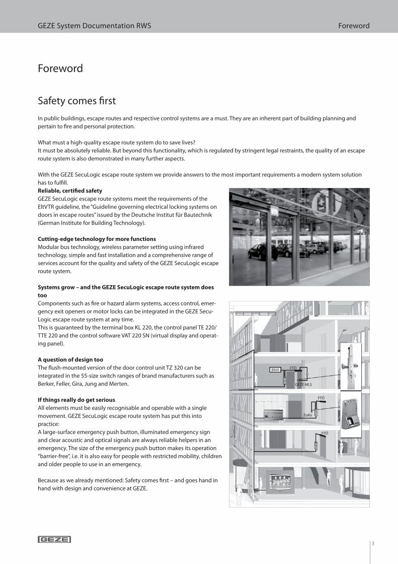
GEZE System Documentation RWS Foreword
Foreword
Safety comes ! rst
In public buildings, escape routes and respective control systems are a must. They are an inherent part of building planning and
pertain to ! re and personal protection.
What must a high-quality escape route system do to save lives?
It must be absolutely reliable. But beyond this functionality, which is regulated by stringent legal restraints, the quality of an escape
route system is also demonstrated in many further aspects.
With the GEZE SecuLogic escape route system we provide answers to the most important requirements a modern system solution
has to ful! ll.
Reliable, certi� ed safety
GEZE SecuLogic escape route systems meet the requirements of the
EltVTR guideline, the “Guideline governing electrical locking systems on
doors in escape routes” issued by the Deutsche Institut für Bautechnik
(German Institute for Building Technology).
Cutting-edge technology for more functions
Modular bus technology, wireless parameter setting using infrared
technology, simple and fast installation and a comprehensive range of
services account for the quality and safety of the GEZE SecuLogic escape
route system.
Systems grow – and the GEZE SecuLogic escape route system does
too
Components such as ! re or hazard alarm systems, access control, emer-
gency exit openers or motor locks can be integrated in the GEZE Secu-
Logic escape route system at any time.
This is guaranteed by the terminal box KL 220, the control panel TE 220/
TTE 220 and the control software VAT 220 SN (virtual display and operat-
ing panel).
A question of design too
The # ush-mounted version of the door control unit TZ 320 can be
integrated in the 55-size switch ranges of brand manufacturers such as
Berker, Feller, Gira, Jung and Merten.
If things really do get serious
All elements must be easily recognisable and operable with a single
movement. GEZE SecuLogic escape route system has put this into
practice:
A large-surface emergency push button, illuminated emergency sign
and clear acoustic and optical signals are always reliable helpers in an
emergency. The size of the emergency push button makes its operation
“barrier-free”, i.e. it is also easy for people with restricted mobility, children
and older people to use in an emergency.
Because as we already mentioned: Safety comes ! rst – and goes hand in
hand with design and convenience at GEZE.
ZuKo
BMA
GEZE MLS
FTÖ
FTÖ
FTÖ

4
GEZE System Documentation RWS Foreword
c Aborting the short-term release:
When this is aborted, the door is locked prematurely when it is closed and the short-term release has not expired. This prevents
the door being accessible for unauthorised people after someone has passed through it.
The abortion setting can be deactivated via the service menu. In this case, the door remains unlocked for the duration of the time
set. The release time can be ended prematurely by actuating the key switch again.
c Direct release (in accordance with EltVTR)
Safety-related interruption of power supply to the electrical locking system by means of an opener contact when the emergency
push button is actuated.
c Unlocking (in accordance with EltVTR):
Non-safety-related interruption of the power supply to the electrical locking system e.g. through a key switch.
c Indirect release (in accordance with EltVTR):
Safety-related interruption of the power supply to the electrical locking system if a further switching process is triggered by the
opener contact of the emergency push button, with this new process interrupting the power supply to the electrical locking
system.
c After-triggering the short-term release:
If a new short-term release is triggered during the release time, the release time begins again.
The after-triggering setting can be deactivated via the service menu. If a new short-term release is triggered during the release
time by means of the internal key switch or a programmable input, the system locks again.
c Emergency unlocking (in accordance with EltVTR):
Non safety-related interruption of the power supply to the electrical locking system e.g. through a hazard alarm system (GMA) or
similar automatic triggering device.
c Pre-alarm:
If the release time is exceeded during passage, an acoustic signal is sounded which informs the user that the time has been
exceeded. If the door is closed during a pre-alarm, it is automatically locked and the pre-alarm is reset.
c Door alarm:
If the pre-alarm time is also exceeded, the so-called door alarm is triggered. This can be reset via the integrated key switch or all
inputs “short-term release” as well as via the control panel TE220 or the visualisation VAT 220 SN. If the door is closed during a
door alarm, the door will be locked and can only be unlocked again once the alarm has been reset (except if the emergency push
button is pressed). A door alarm will also be given if the door is “broken open”, in other words when the door is opened by force or
without prior release.
Terms and de! nitions
5
GEZE System Documentation RWS Foreword
AP Surface-mounted version
BLE 220 Flashlight
BMA Fire alarm system
EMA Burglar alarm system
FS Latch lock
FTÖ Emergency exit opener
FWS Emergency exit route sign
GLT Building management system
GMA Hazard alarm system
IQ Lock C Contact lock
IQ Lock EL Motor lock
IQ Lock EM Lever lock
IQ Lock M Motor lock
KL 220 Terminal box
KZF Short-term release
MA 500 Holding magnet
NC Potential-free opener contact (normal closed)
NO Potential-free closer contact (normal open)
NOT 320 Emergency push button
NT Power supply
OK Upper edge
RWA Smoke and heat extraction system
SCT 221 Key switch, one-pole switch (closer)
SCT 222 Key switch with LED display, one-pole reversible switch (two closers)
SCT 320 Key switch, one-pole reversible switch (two closers)
SHB 220 Signal horn with � ashlight
SLE 220 Signal light
SLH 220 Signal horn
TE 220 Control panel
TZ 320 Door control unit using bus technology
TZ 322 Door control unit using bus technology without emergency push button
TZ 323 Door control unit using bus technology, turned through 180°
... B Door control unit with illuminated emergency exit route sign
... S Door control unit with key switch (connection via ribbon cable)
... N Door control unit with integrated power supply
... BSN Door control unit with illuminated emergency exit route sign, key switch and integrated power supply
... BS Door control unit with illuminated emergency exit route sign and key switch
... SN Door control unit with key switch and integrated power supply
UK Lower edge
UP Flush-mounted version
USV Uninterruptible power supply
VAT 220 SN Visualisation software
ZSU Timer
ZuKo Access control
Abbreviations
Example for the name of the door control unit:
Door control unit with illuminated emergency exit route sign with key switch Description
TZ 320 B S = TZ 320 BS
6
GEZE System Documentation RWS Foreword
The GEZE SecuLogic RWS was designed according to the latest technical standards and recognised safety-related regulations.
Nevertheless, hazards can still occur during installation and application. For this reason, please note the following instructions:
c Basic safety instructions
– Start-up and maintenance may only be carried out by a quali! ed electrician or an expert trained by GEZE.
– Only genuine GEZE spare parts or accessories approved by GEZE may be used.
– Unauthorised modi! cations to the system exclude GEZE’s liability for any resulting damage.
– Primary protective measures are to be carried out on side.
– Respective national standards must be heeded when laying cables.
c Proper use
The GEZE SecuLogic RWS system has been designed for the control and monitoring of electrically locked emergency exit routes. External products may only be used after consultation with GEZE.
c Improper use
The connection of products which have not been expressly approved for use by GEZE constitutes improper use.
Safety and responsibility
How to lay cables safely
Here are a few tips to help you lay the required cables safely and precisely:
c Interference-free
Do not lay the data cable parallel to high-voltage cables (electromagnetic interference)!
c The right cable
Shielded cable with twisted pairs of conductors.
Peripherals
• J-Y(ST)Y 2x2x0.6
• J-Y(ST)Y 4x2x0.6
Mains cable
• NYM-J 3x1.5
Bus cabling
• J-Y(ST)Y 2x2x0.8
• J-Y(ST)Y 4x2x0.8
c Structure or networking
Do not route the bus line in a star shape, but rather in series.
Cable speci! cation
7
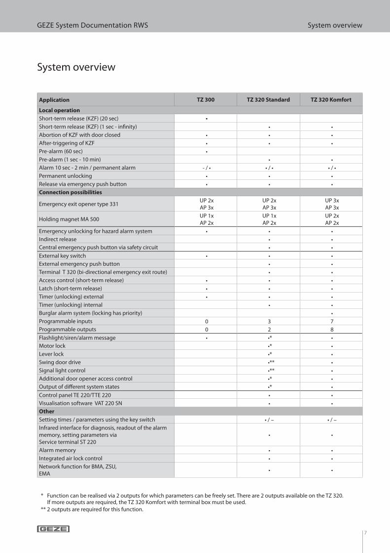
GEZE System Documentation RWS System overview
System overview
Application TZ 300 TZ 320 Standard TZ 320 Komfort
Local operation
Short-term release (KZF) (20 sec) •
Short-term release (KZF) (1 sec - in! nity) • •
Abortion of KZF with door closed • • •
After-triggering of KZF • • •
Pre-alarm (60 sec) •
Pre-alarm (1 sec - 10 min) • •
Alarm 10 sec - 2 min / permanent alarm - / • • / • • / •
Permanent unlocking • • •
Release via emergency push button • • •
Connection possibilities
Emergency exit opener type 331UP 2xAP 3x
UP 2xAP 3x
UP 3xAP 3x
Holding magnet MA 500UP 1xAP 2x
UP 1xAP 2x
UP 2xAP 2x
Emergency unlocking for hazard alarm system • • •
Indirect release • •
Central emergency push button via safety circuit • •
External key switch • • •
External emergency push button • •
Terminal T 320 (bi-directional emergency exit route) • •
Access control (short-term release) • • •
Latch (short-term release) • • •
Timer (unlocking) external • • •
Timer (unlocking) internal • •
Burglar alarm system (locking has priority) •
Programmable inputs 0 3 7
Programmable outputs 0 2 8
Flashlight/siren/alarm message • •* •
Motor lock •* •
Lever lock •* •
Swing door drive •** •
Signal light control •** •
Additional door opener access control •* •
Output of di" erent system states •* •
Control panel TE 220/TTE 220 • •
Visualisation software VAT 220 SN • •
Other
Setting times / parameters using the key switch • / – • / –
Infrared interface for diagnosis, readout of the alarm
memory, setting parameters via
Service terminal ST 220
• •
Alarm memory • •
Integrated air lock control • •
Network function for BMA, ZSU,
EMA• •
* Function can be realised via 2 outputs for which parameters can be freely set. There are 2 outputs available on the TZ 320. If more outputs are required, the TZ 320 Komfort with terminal box must be used.
** 2 outputs are required for this function.
8
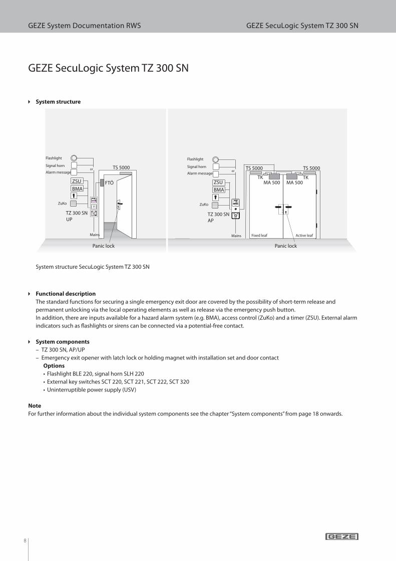
GEZE System Documentation RWS GEZE SecuLogic System TZ 300 SN
TZ 300 SNUP
TS 5000
FTÖ
TZ 300 SNAP
TS 5000TS 5000
TK TKMA 500 MA 500
GEZE SecuLogic System TZ 300 SN
System structure SecuLogic System TZ 300 SN
c Functional description
The standard functions for securing a single emergency exit door are covered by the possibility of short-term release and
permanent unlocking via the local operating elements as well as release via the emergency push button.
In addition, there are inputs available for a hazard alarm system (e.g. BMA), access control (ZuKo) and a timer (ZSU). External alarm
indicators such as ! ashlights or sirens can be connected via a potential-free contact.
c System components
– TZ 300 SN, AP/UP
– Emergency exit opener with latch lock or holding magnet with installation set and door contact
Options
• Flashlight BLE 220, signal horn SLH 220
• External key switches SCT 220, SCT 221, SCT 222, SCT 320
• Uninterruptible power supply (USV)
Note
For further information about the individual system components see the chapter “System components” from page 18 onwards.
c System structure
ZuKo ZuKo
BMA BMA
ZSU ZSU
Mains Mains
Panic lock Panic lock
Signal hornor
or
Signal horn
Flashlight Flashlight
Fixed leaf Active leaf
Alarm message Alarm message
9
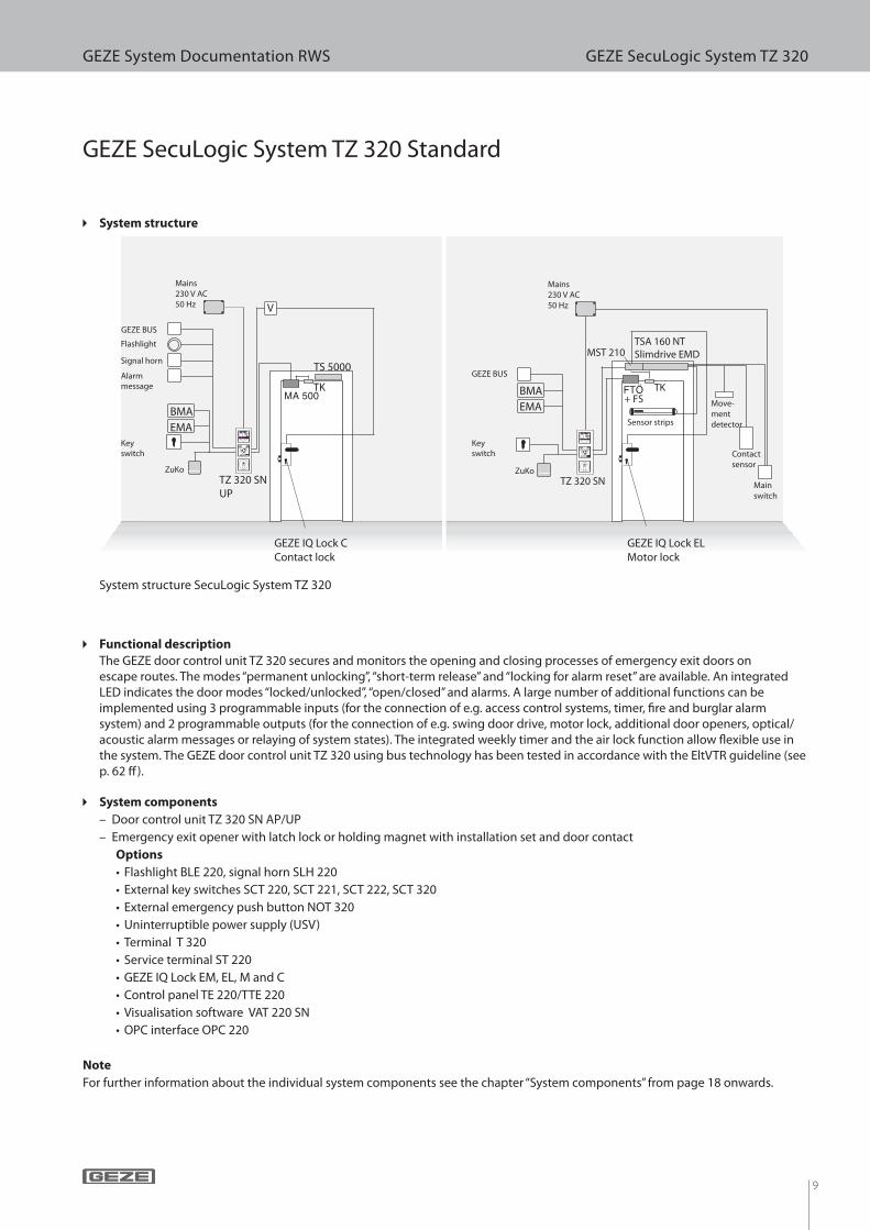
GEZE System Documentation RWS GEZE SecuLogic System TZ 320
TS 5000
TK
V
TZ 320 SNUP
TK
TSA 160 NTSlimdrive EMDMST 210
TZ 320 SN
+ FS
GEZE SecuLogic System TZ 320 Standard
System structure SecuLogic System TZ 320
c Functional description
The GEZE door control unit TZ 320 secures and monitors the opening and closing processes of emergency exit doors on escape routes. The modes “permanent unlocking”, “short-term release” and “locking for alarm reset” are available. An integrated LED indicates the door modes “locked/unlocked”, “open/closed” and alarms. A large number of additional functions can be implemented using 3 programmable inputs (for the connection of e.g. access control systems, timer, ! re and burglar alarm system) and 2 programmable outputs (for the connection of e.g. swing door drive, motor lock, additional door openers, optical/acoustic alarm messages or relaying of system states). The integrated weekly timer and the air lock function allow " exible use in the system. The GEZE door control unit TZ 320 using bus technology has been tested in accordance with the EltVTR guideline (see p. 62 # ).
c System components
– Door control unit TZ 320 SN AP/UP
– Emergency exit opener with latch lock or holding magnet with installation set and door contact
Options
• Flashlight BLE 220, signal horn SLH 220
• External key switches SCT 220, SCT 221, SCT 222, SCT 320
• External emergency push button NOT 320
• Uninterruptible power supply (USV)
• Terminal T 320
• Service terminal ST 220
• GEZE IQ Lock EM, EL, M and C
• Control panel TE 220/TTE 220
• Visualisation software VAT 220 SN
• OPC interface OPC 220
Note
For further information about the individual system components see the chapter “System components” from page 18 onwards.
c System structure
ZuKo
BMA
Mains230 V AC50 Hz
Mains230 V AC50 Hz
GEZE IQ Lock EL Motor lock
EMA
Signal horn
Flashlight
GEZE BUS
Alarmmessage
GEZE IQ Lock C Contact lock
GEZE BUS
BMA
EMA
ZuKo
Keyswitch
Keyswitch
Sensor strips
Contactsensor
Move-mentdetector
Mainswitch
10
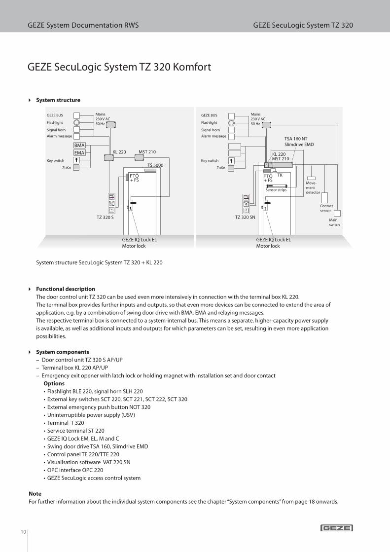
GEZE System Documentation RWS GEZE SecuLogic System TZ 320
KL 220
TK
TSA 160 NTSlimdrive EMD
MST 210
TZ 320 SN
+ FS
KL 220
TZ 320 S
MST 210
TS 5000
+ FS
GEZE SecuLogic System TZ 320 Komfort
System structure SecuLogic System TZ 320 + KL 220
c Functional description
The door control unit TZ 320 can be used even more intensively in connection with the terminal box KL 220.
The terminal box provides further inputs and outputs, so that even more devices can be connected to extend the area of
application, e.g. by a combination of swing door drive with BMA, EMA and relaying messages.
The respective terminal box is connected to a system-internal bus. This means a separate, higher-capacity power supply
is available, as well as additional inputs and outputs for which parameters can be set, resulting in even more application
possibilities.
c System components
– Door control unit TZ 320 S AP/UP
– Terminal box KL 220 AP/UP
– Emergency exit opener with latch lock or holding magnet with installation set and door contact
Options
• Flashlight BLE 220, signal horn SLH 220
• External key switches SCT 220, SCT 221, SCT 222, SCT 320
• External emergency push button NOT 320
• Uninterruptible power supply (USV)
• Terminal T 320
• Service terminal ST 220
• GEZE IQ Lock EM, EL, M and C
• Swing door drive TSA 160, Slimdrive EMD
• Control panel TE 220/TTE 220
• Visualisation software VAT 220 SN
• OPC interface OPC 220
• GEZE SecuLogic access control system
Note
For further information about the individual system components see the chapter “System components” from page 18 onwards.
c System structure
ZuKo ZuKo
BMA
GEZE IQ Lock EL Motor lock
GEZE IQ Lock EL Motor lock
EMA
Signal horn Signal horn
Flashlight Flashlight
GEZE BUS GEZE BUS
Alarm message Alarm message
Key switch Key switch
Mains230 V AC50 Hz
Mains230 V AC50 Hz
Move-mentdetector
Contactsensor
Mainswitch
Sensor strips
11
GEZE System Documentation RWS GEZE SecuLogic System TZ 320
TZ 320 UP
TS 5000
FTÖ+ FS
NTV
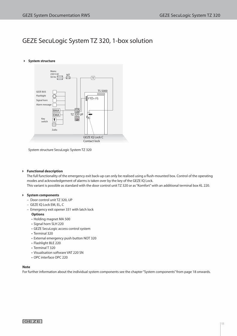
GEZE SecuLogic System TZ 320, 1-box solution
System structure SecuLogic System TZ 320
c System structure
GEZE IQ Lock C Contact lock
ZuKo
BMA
EMA
Signal horn
Flashlight
GEZE BUS
Alarm message
Mains230 V AC50 Hz
Keyswitch
c Functional description
The full functionality of the emergency exit back-up can only be realised using a ! ush-mounted box. Control of the operating
modes and acknowledgement of alarms is taken over by the key of the GEZE IQ Lock.
This variant is possible as standard with the door control unit TZ 320 or as “Komfort” with an additional terminal box KL 220.
c System components
– Door control unit TZ 320, UP
– GEZE IQ Lock EM, EL, C
– Emergency exit opener 331 with latch lock
Options
• Holding magnet MA 500
• Signal horn SLH 220
• GEZE SecuLogic access control system
• Terminal 320
• External emergency push button NOT 320
• Flashlight BLE 220
• Terminal T 320
• Visualisation software VAT 220 SN
• OPC interface OPC 220
Note
For further information about the individual system components see the chapter “System components” from page 18 onwards.

12
GEZE System Documentation RWS GEZE SecuLogic System TZ 320
TZ 320 TZ 320 TZ 320 TZ 320 TZ 320 TZ 320
VAT 220 SN
TE 220/TTE 220
GEZE SecuLogic Vernetzt
System structure SecuLogic Vernetzt
c Functional description
The system SecuLogic Vernetzt is used to secure emergency exit doors subject to central control and monitoring in large
buildings, e.g. shopping centres, malls, public institutions. The individual control components (visualisation software, control
panels and door control units) can be assigned anywhere in the individual bus systems. The maximum cable length for each bus
system is 1000 m.
VAT 220
8 bus systems with a maximum of 63 door control units each can be displayed and operated using the visualisation software VAT
220 SN. The VAT 220 SN can work both as a central and as a parallel operating spot. There is no classic server-client relationship,
because with VAT 220 SN all the doors in the system can be controlled centrally and without a loop via a server. It is possible to set
up further lower-order operating spots with the aid of control panels TE 220/TTE 220.
TE 220/TTE 220
The control panel TE 220 wall panel and the control panel TTE 220 desk panel are used as control and display units for up to 20
individual door control units via a bus system (max. 5 TE 220 per bus system).
OPC
The software interface OPC is used in the escape route system so that data can be transmitted to higher-level building
management systems. The OPC interface guarantees simple communication between devices from di! erent manufacturers.
c System structure
Bus system 1
... up to 63
Bus system 2
Bus system 3
Bus multiplexer
Bus system 4
BMA
EMA
ZSU
13
GEZE System Documentation RWS GEZE SecuLogic System TZ 320
c System components
– Door control unit TZ 320 SN AP/UP
– Door control unit TZ 320 S AP/UP + terminal box KL 220 AP/UP
– Emergency exit opener with latch lock or holding magnet with installation set and door contact
– Visualisation software VAT 220 SN
Options
• Flashlight BLE 220, signal horn SLH 220
• External key switches SCT 220, SCT 221, SCT 222, SCT 320
• External emergency push button NOT 320
• Uninterruptible power supply (USV)
• Control panel TE 220/TTE 220
• Terminal T 320
• Service terminal ST 220
• GEZE IQ Lock EM, EL, M
• Swing door drive TSA 160, Slimdrive EMD
• OPC interface OPC 220
• GEZE SecuLogic access control system
Note
For further information about the individual system components see the chapter “System components” from page 18 onwards.

14
GEZE System Documentation RWS GEZE special systems
TZ 300 SNUP
TS 5000
FTÖ
SCT 221
GEZE special system for children’s nurseries
Special system for children’s nurseries
c Functional description of the children’s nursery solution
The door is permanently locked and secured by the door control unit TZ 300 SN.
Passage by nursery sta!
The sta! trigger a short-term release at the TZ 300 SN via the outer key switch and so can pass through the door using the key on
the panic lock. The outer door handle is coupled in during the day via the switchover function “B” of the panic lock.
Arrival and collection times
The external push button can be activated or deactivated via the switch in the “sta! room”. This means that parents can trigger a
short-term release when they are bringing or collecting their children, and open the door via the coupled-in door handle. Parents
can leave the nursery again by opening the door using the push button mounted at a height of 1.80 m. This installation height of
1.80 m means that children cannot reach the button.
Emergencies
In an emergency, the door can always be passed through in the direction of emergency exit by pressing the emergency push
button. Triggering of the emergency push button is indicated by both an optical and acoustic signal on the TZ 300. Optionally, the
alarm can be relayed. This allows an external light or siren to be triggered.
Fire
A " re alarm system can be connected to the TZ 300 for immediate emergency unlocking in the event of a " re. This means the door
control unit has already been unlocked when people escaping the " re arrive at the door.
c System components
– Door control unit TZ 300 SN
– Emergency exit opener with latch lock or holding magnet with installation set and door contact
– Release push button inside at a height of 1.80 m
– Release push button outside
– Circuit breaker
– External key switch SCT 221
– Panic lock, function “B” (on site)
Options
• Flashlight BLE 220, signal horn SLH 220
• Uninterruptible power supply (USV)
Note
For further information about the individual system components see the chapter “System components” from page 18 onwards.
c System structure children’s nursery solution
Push button
1.80 m
Key switch
(sta! room)
Alarm message
Push button
outside
Mains
Panic lock
Function “B” (handle/handle)
BMA
15
GEZE System Documentation RWS GEZE special systems
TZ 320 SNinnen
T 320außen
TS 5000
FTÖ
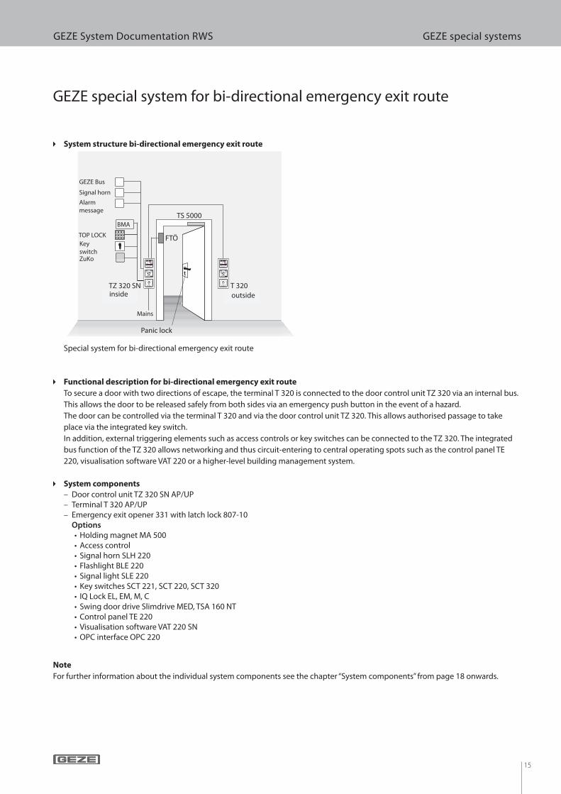
Special system for bi-directional emergency exit route
c Functional description for bi-directional emergency exit route
To secure a door with two directions of escape, the terminal T 320 is connected to the door control unit TZ 320 via an internal bus.
This allows the door to be released safely from both sides via an emergency push button in the event of a hazard.
The door can be controlled via the terminal T 320 and via the door control unit TZ 320. This allows authorised passage to take
place via the integrated key switch.
In addition, external triggering elements such as access controls or key switches can be connected to the TZ 320. The integrated
bus function of the TZ 320 allows networking and thus circuit-entering to central operating spots such as the control panel TE
220, visualisation software VAT 220 or a higher-level building management system.
c System components
– Door control unit TZ 320 SN AP/UP – Terminal T 320 AP/UP – Emergency exit opener 331 with latch lock 807-10Options
• Holding magnet MA 500• Access control• Signal horn SLH 220• Flashlight BLE 220• Signal light SLE 220• Key switches SCT 221, SCT 220, SCT 320• IQ Lock EL, EM, M, C• Swing door drive Slimdrive MED, TSA 160 NT• Control panel TE 220• Visualisation software VAT 220 SN• OPC interface OPC 220
Note
For further information about the individual system components see the chapter “System components” from page 18 onwards.
c System structure bi-directional emergency exit route
GEZE Bus
Mains
Signal horn
ZuKo
Keyswitch
TOP LOCK
Alarmmessage
BMA
Panic lock
GEZE special system for bi-directional emergency exit route
inside outside

16
GEZE System Documentation RWS GEZE special systems
+ FS
TS 5000
NT
+ FS
TS 5000
NT
+ FS
TS 5000
NT
GEZE special system for areas without local emergency push button
Special system for areas without local emergency push button
c Functional description
Securing emergency exit doors in areas with a local emergency push button in accordance with EltVTR (DIBT 5/98) section 2.6,
para. 3.1.3 and building regulation list A
Part 1, e.g. psychiatric units, care areas for dementia patients, forensic areas.
The safety circuit is a separate power circuit to realise a safety-related (indirect) release of several door control units in connection
with central emergency push buttons, BMA or similar. The safety circuit is used in particular when there is no local emergency
push button on the door control unit. This must be approved by national top-level building authorities in individual cases.
c System components
– Door control unit TZ 322 SN AP/UP without emergency push button
– Key switch SCT 222 with LEDs
– Relay board RP 220
– Emergency push button NOT 320
– Emergency exit opener with latch lock or holding magnet with installation set and door contact
Options
• GEZE IQ Lock EL, EM, M and C
• Flashlight BLE 220/signal horn SLH 220
• Swing door drive TSA 160, Slimdrive EMD
• Control panel TE 220/TTE 220
• Terminal T 320
• Service terminal ST 220
• Visualisation software VAT 220 SN
• Uninterruptible power supply (USV)
Note
For further information about the individual system components see the chapter “System components” from page 18 onwards.
c System structure
Panic lock
Safety circuit
Mains Mains
Central spotBMA
TZ 322+
RP 220
TZ 322+
RP 220
TZ 322+
RP 220
USV
NOT 320TE 220
Mains
Mains
SCT 222inside
SCT 222outside
SCT 222outside
SCT 222outside
SCT 222inside
SCT 222insideZuKo
Panic lock Panic lock
17
GEZE System Documentation RWS GEZE special systems
+ FS+ FS
VBVB
+ FS+ FS
TS 5000TS 5000 TS 5000 TS 5000
TZ 320 SN TZ 320 SNTZ 320 SN TZ 320 SN
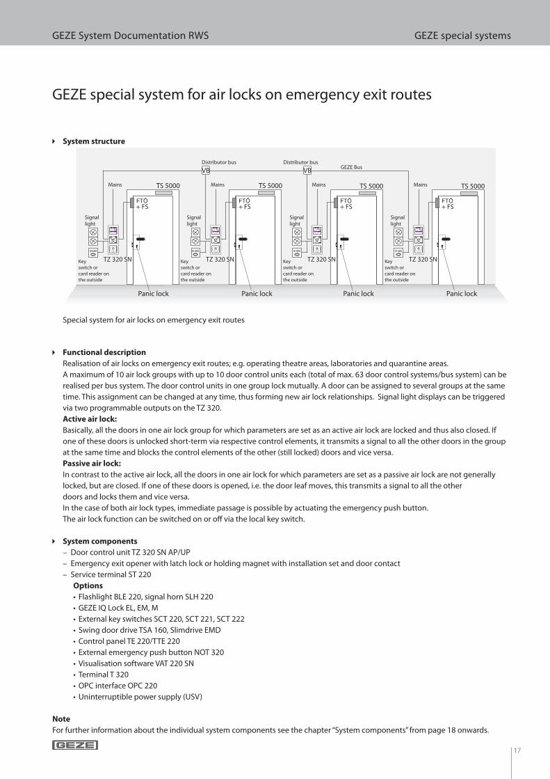
GEZE special system for air locks on emergency exit routes
Special system for air locks on emergency exit routes
c Functional description
Realisation of air locks on emergency exit routes; e.g. operating theatre areas, laboratories and quarantine areas.
A maximum of 10 air lock groups with up to 10 door control units each (total of max. 63 door control systems/bus system) can be
realised per bus system. The door control units in one group lock mutually. A door can be assigned to several groups at the same
time. This assignment can be changed at any time, thus forming new air lock relationships. Signal light displays can be triggered
via two programmable outputs on the TZ 320.
Active air lock:
Basically, all the doors in one air lock group for which parameters are set as an active air lock are locked and thus also closed. If
one of these doors is unlocked short-term via respective control elements, it transmits a signal to all the other doors in the group
at the same time and blocks the control elements of the other (still locked) doors and vice versa.
Passive air lock:
In contrast to the active air lock, all the doors in one air lock for which parameters are set as a passive air lock are not generally
locked, but are closed. If one of these doors is opened, i.e. the door leaf moves, this transmits a signal to all the other
doors and locks them and vice versa.
In the case of both air lock types, immediate passage is possible by actuating the emergency push button.
The air lock function can be switched on or o! via the local key switch.
c System components
– Door control unit TZ 320 SN AP/UP
– Emergency exit opener with latch lock or holding magnet with installation set and door contact
– Service terminal ST 220
Options
• Flashlight BLE 220, signal horn SLH 220
• GEZE IQ Lock EL, EM, M
• External key switches SCT 220, SCT 221, SCT 222
• Swing door drive TSA 160, Slimdrive EMD
• Control panel TE 220/TTE 220
• External emergency push button NOT 320
• Visualisation software VAT 220 SN
• Terminal T 320
• OPC interface OPC 220
• Uninterruptible power supply (USV)
Note
For further information about the individual system components see the chapter “System components” from page 18 onwards.
c System structure
Key
switch or
card reader on
the outside
Panic lock
Signal light
Mains Mains Mains Mains
Signal light
Signal light
Signal light
GEZE Bus
Panic lock Panic lock Panic lock
Key
switch or
card reader on
the outside
Key
switch or
card reader on
the outside
Key
switch or
card reader on
the outside
Distributor bus Distributor bus

18
GEZE System Documentation RWS GEZE Door Control Unit TZ 300 SN
GEZE Door Control Unit TZ 300 SN
GEZE door control unit TZ 300 UP GEZE door control unit TZ 300 AP
c Product features
– 3 LED displays for door modes
• Locked, unlocked
• Door leaf open, closed
• Alarm, pre-alarm
– Integrated illuminated emergency push button
– integrated key switch for
• Unlocking, short-term release
• Locking
• Alarm reset
– Integrated di! erentiated acoustic alarm for indication of the pre-alarm or actuation of the emergency push button
– Integrated sabotage protection
– Automatic abortion of short-term release when the door is closed
– Automatic storage and activation of operating state before and after power failure.
– Flush-mounted installation in 3 " ush-mounting boxes 62.5 mm deep
The GEZE door control unit TZ 300 SN is part of the SecuLogic escape route system and is used to control and monitor electrically
locked doors on emergency exit routes.
Doors on emergency exit routes are reliably protected against unauthorised passage by the GEZE door control unit. At the same
time, the integrated emergency push button guarantees passage at all times in emergency situations.
Technical product description
Dimensions (B x H x D) Flush-mounted version 81 x 223 x 62.5 mm
Surface-mounted version 77 x 197 x 88 mm
Integrated power supply Flush-mounted version 500 mA, 350 mA for peripherals
Surface-mounted version 800 mA, 350 mA for peripherals
Connections Input for emergency unlocking through hazard alarm system
Input for access control system and timer
Potential-free output for optical/acoustic alarm indication or alarm relaying
Connection possibility for locking elements
Flush-mounted version 2 x FTÖ, 1 x holding magnet
Surface-mounted version 3 x FTÖ, 2 x holding magnet
Area of use Dry rooms
c Technical data GEZE door control unit TZ 300 SN
19
GEZE System Documentation RWS GEZE Door Control Unit TZ 320
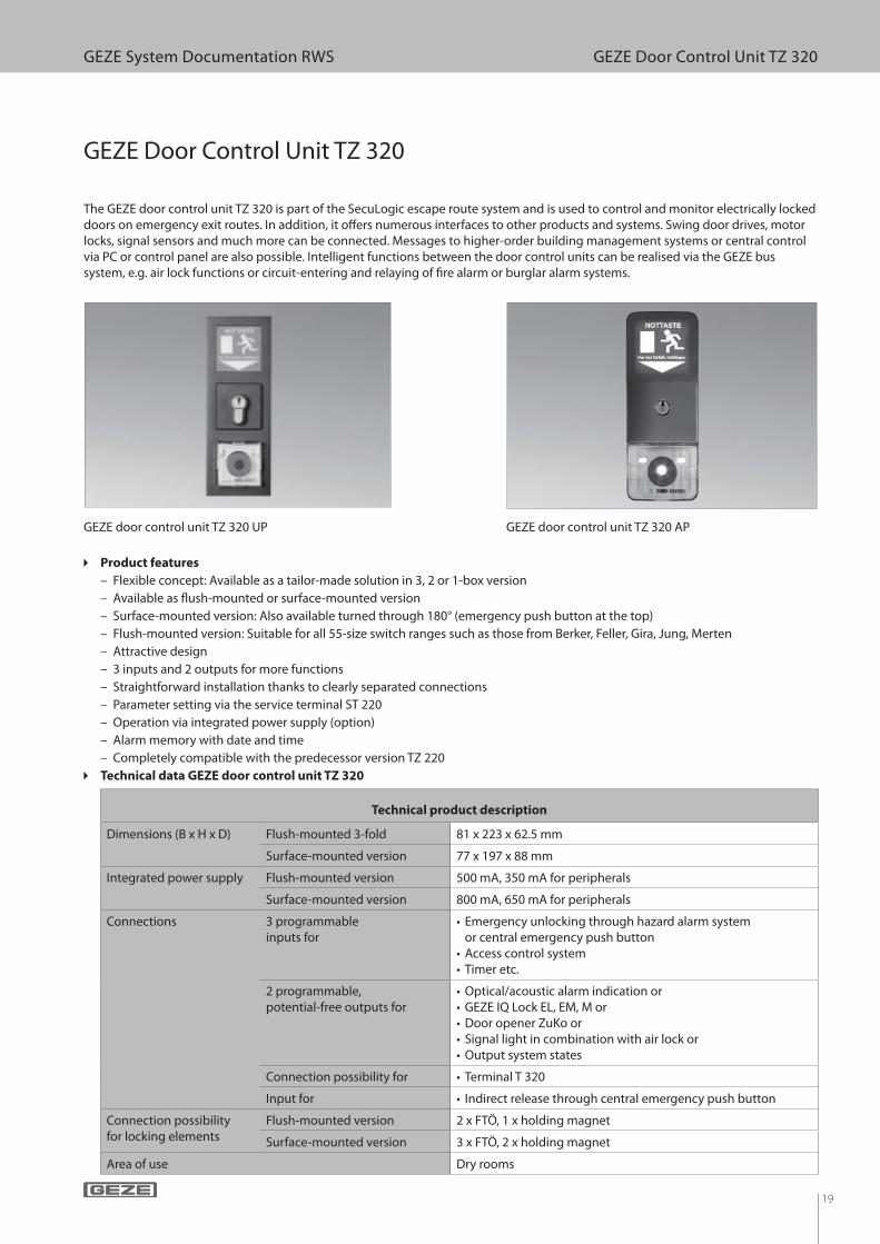
GEZE Door Control Unit TZ 320
GEZE door control unit TZ 320 UP GEZE door control unit TZ 320 AP
c Product features
– Flexible concept: Available as a tailor-made solution in 3, 2 or 1-box version
– Available as ! ush-mounted or surface-mounted version
– Surface-mounted version: Also available turned through 180° (emergency push button at the top)
– Flush-mounted version: Suitable for all 55-size switch ranges such as those from Berker, Feller, Gira, Jung, Merten
– Attractive design
– 3 inputs and 2 outputs for more functions
– Straightforward installation thanks to clearly separated connections
– Parameter setting via the service terminal ST 220
– Operation via integrated power supply (option)
– Alarm memory with date and time
– Completely compatible with the predecessor version TZ 220
The GEZE door control unit TZ 320 is part of the SecuLogic escape route system and is used to control and monitor electrically locked doors on emergency exit routes. In addition, it o# ers numerous interfaces to other products and systems. Swing door drives, motor locks, signal sensors and much more can be connected. Messages to higher-order building management systems or central control via PC or control panel are also possible. Intelligent functions between the door control units can be realised via the GEZE bus system, e.g. air lock functions or circuit-entering and relaying of $ re alarm or burglar alarm systems.
Technical product description
Dimensions (B x H x D) Flush-mounted 3-fold 81 x 223 x 62.5 mm
Surface-mounted version 77 x 197 x 88 mm
Integrated power supply Flush-mounted version 500 mA, 350 mA for peripherals
Surface-mounted version 800 mA, 650 mA for peripherals
Connections 3 programmable inputs for
• Emergency unlocking through hazard alarm system or central emergency push button
• Access control system • Timer etc.
2 programmable, potential-free outputs for
• Optical/acoustic alarm indication or • GEZE IQ Lock EL, EM, M or • Door opener ZuKo or • Signal light in combination with air lock or • Output system states
Connection possibility for • Terminal T 320
Input for • Indirect release through central emergency push button
Connection possibility for locking elements
Flush-mounted version 2 x FTÖ, 1 x holding magnet
Surface-mounted version 3 x FTÖ, 2 x holding magnet
Area of use Dry rooms
c Technical data GEZE door control unit TZ 320
20
GEZE System Documentation RWS GEZE Terminal Box KL 220
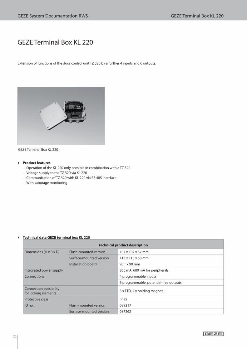
GEZE Terminal Box KL 220
GEZE Terminal Box KL 220
c Product features
– Operation of the KL 220 only possible in combination with a TZ 320
– Voltage supply to the TZ 320 via KL 220
– Communication of TZ 320 with KL 220 via RS 485 interface
– With sabotage monitoring
Extension of functions of the door control unit TZ 320 by a further 4 inputs and 6 outputs.
Technical product description
Dimensions (H x B x D) Flush-mounted version 107 x 107 x 57 mm
Surface-mounted version 113 x 113 x 58 mm
Installation board 90 x 90 mm
Integrated power supply 800 mA, 600 mA for peripherals
Connections 4 programmable inputs
6 programmable, potential-free outputs
Connection possibility for locking elements
3 x FTÖ, 2 x holding magnet
Protective class IP 55
ID no. Flush-mounted version 089317
Surface-mounted version 087262
c Technical data GEZE terminal box KL 220
21
GEZE System Documentation RWS GEZE Control Panel TE 220/TTE 220
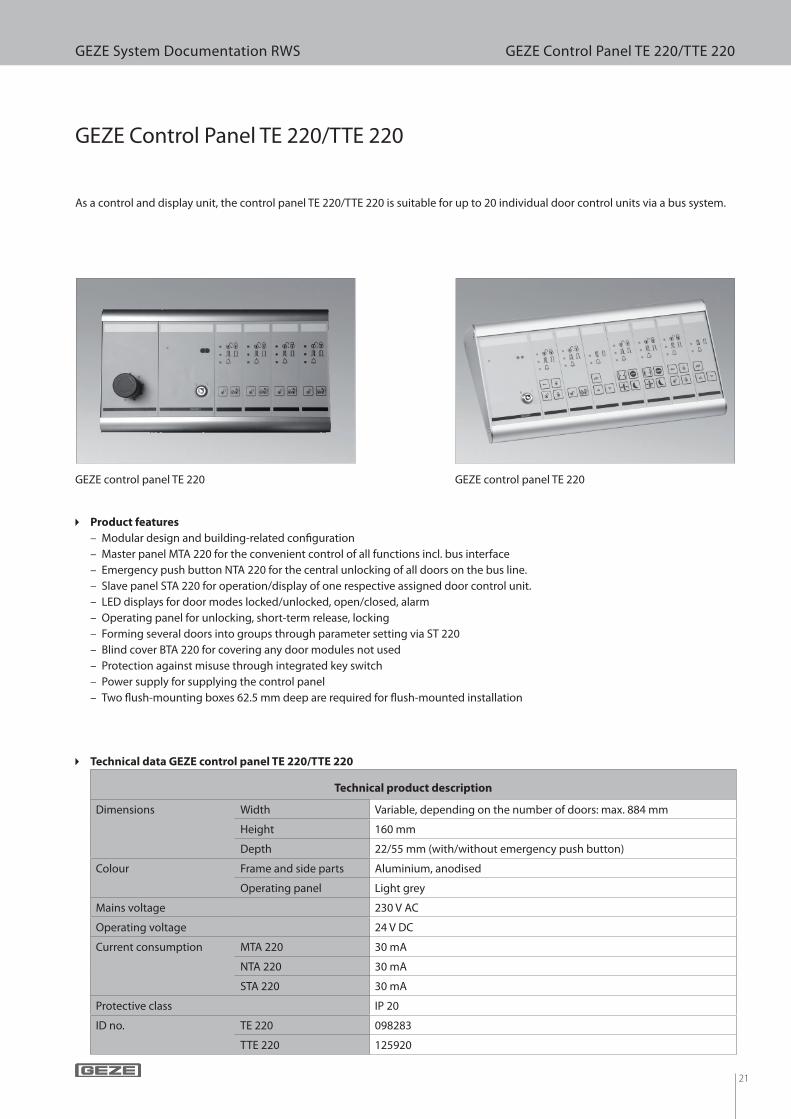
GEZE Control Panel TE 220/TTE 220
GEZE control panel TE 220 GEZE control panel TE 220
c Product features
– Modular design and building-related con! guration
– Master panel MTA 220 for the convenient control of all functions incl. bus interface
– Emergency push button NTA 220 for the central unlocking of all doors on the bus line.
– Slave panel STA 220 for operation/display of one respective assigned door control unit.
– LED displays for door modes locked/unlocked, open/closed, alarm
– Operating panel for unlocking, short-term release, locking
– Forming several doors into groups through parameter setting via ST 220
– Blind cover BTA 220 for covering any door modules not used
– Protection against misuse through integrated key switch
– Power supply for supplying the control panel
– Two " ush-mounting boxes 62.5 mm deep are required for " ush-mounted installation
As a control and display unit, the control panel TE 220/TTE 220 is suitable for up to 20 individual door control units via a bus system.
Technical product description
Dimensions Width Variable, depending on the number of doors: max. 884 mm
Height 160 mm
Depth 22/55 mm (with/without emergency push button)
Colour Frame and side parts Aluminium, anodised
Operating panel Light grey
Mains voltage 230 V AC
Operating voltage 24 V DC
Current consumption MTA 220 30 mA
NTA 220 30 mA
STA 220 30 mA
Protective class IP 20
ID no. TE 220 098283
TTE 220 125920
c Technical data GEZE control panel TE 220/TTE 220
22
GEZE System Documentation RWS Accessories
Accessories
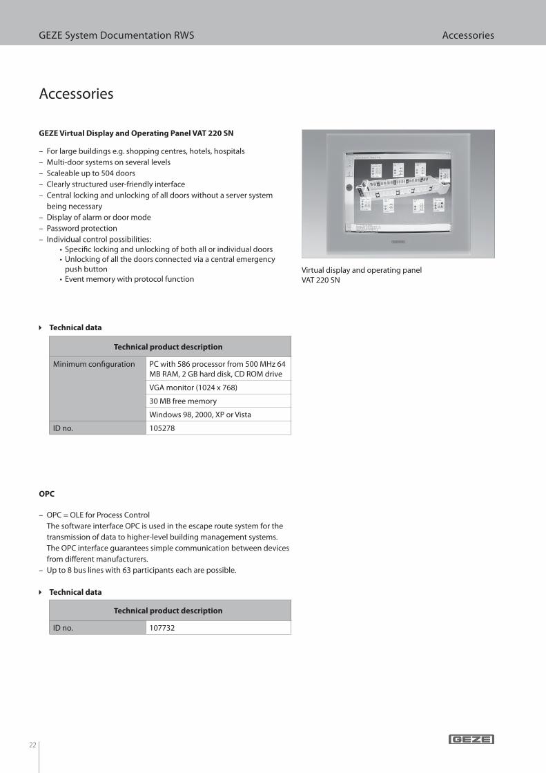
Virtual display and operating panel VAT 220 SN
GEZE Virtual Display and Operating Panel VAT 220 SN
Technical product description
Minimum con! guration PC with 586 processor from 500 MHz 64 MB RAM, 2 GB hard disk, CD ROM drive
VGA monitor (1024 x 768)
30 MB free memory
Windows 98, 2000, XP or Vista
ID no. 105278
c Technical data
– For large buildings e.g. shopping centres, hotels, hospitals
– Multi-door systems on several levels
– Scaleable up to 504 doors
– Clearly structured user-friendly interface
– Central locking and unlocking of all doors without a server system
being necessary
– Display of alarm or door mode
– Password protection
– Individual control possibilities:• Speci! c locking and unlocking of both all or individual doors• Unlocking of all the doors connected via a central emergency
push button• Event memory with protocol function
– OPC = OLE for Process Control
The software interface OPC is used in the escape route system for the
transmission of data to higher-level building management systems.
The OPC interface guarantees simple communication between devices
from di" erent manufacturers.
– Up to 8 bus lines with 63 participants each are possible.
OPC
Technical product description
ID no. 107732
c Technical data
23
GEZE System Documentation RWS Accessories
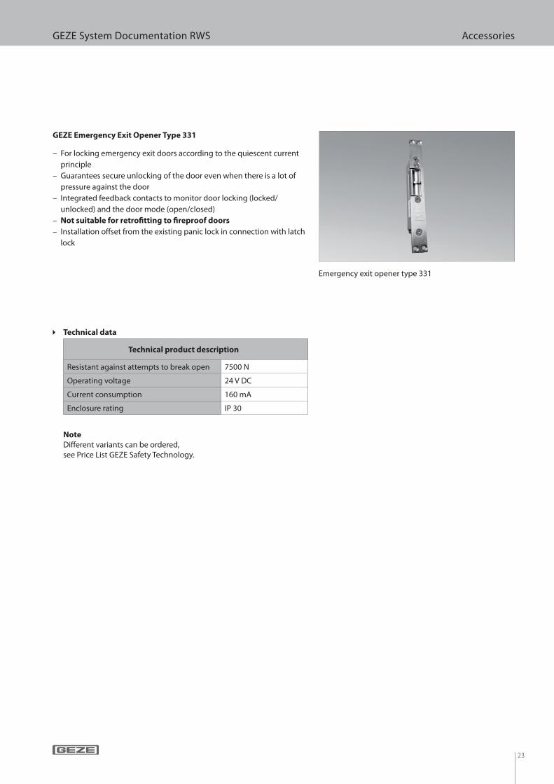
Emergency exit opener type 331
GEZE Emergency Exit Opener Type 331
Technical product description
Resistant against attempts to break open 7500 N
Operating voltage 24 V DC
Current consumption 160 mA
Enclosure rating IP 30
c Technical data
– For locking emergency exit doors according to the quiescent current
principle
– Guarantees secure unlocking of the door even when there is a lot of
pressure against the door
– Integrated feedback contacts to monitor door locking (locked/
unlocked) and the door mode (open/closed)
– Not suitable for retro! tting to ! reproof doors
– Installation o! set from the existing panic lock in connection with latch
lock
Note
Di! erent variants can be ordered, see Price List GEZE Safety Technology.
24
GEZE System Documentation RWS Accessories
– Mortice latch lock as counterpart to the emergency exit door opener
– Adjustable latch
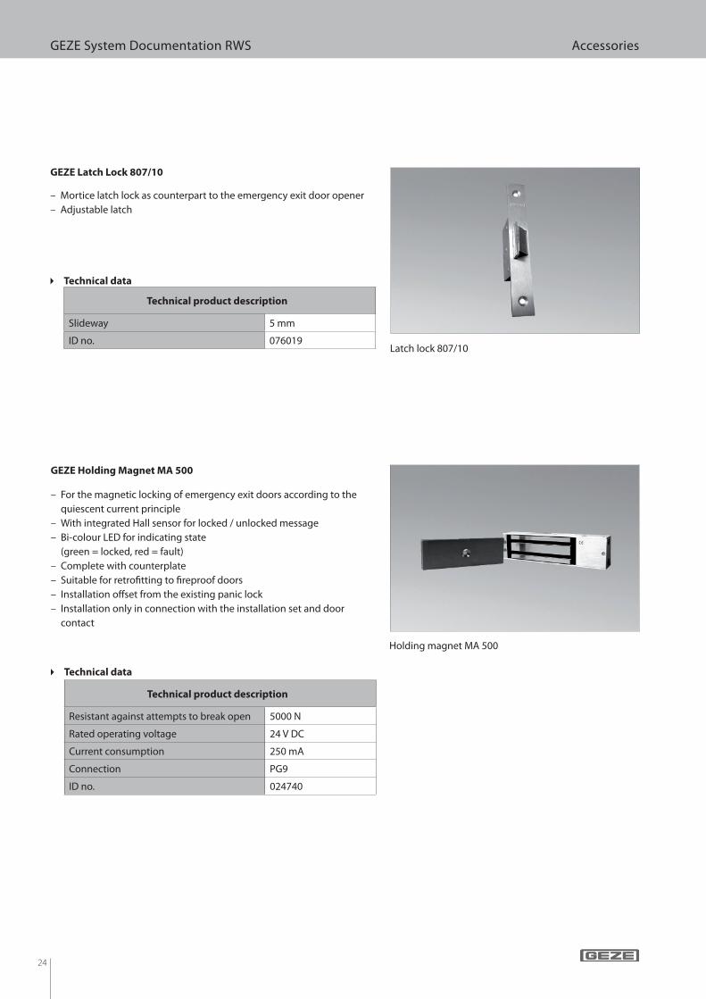
Latch lock 807/10
GEZE Latch Lock 807/10
Technical product description
Slideway 5 mm
ID no. 076019
c Technical data
– For the magnetic locking of emergency exit doors according to the
quiescent current principle
– With integrated Hall sensor for locked / unlocked message
– Bi-colour LED for indicating state
(green = locked, red = fault)
– Complete with counterplate
– Suitable for retro! tting to ! reproof doors
– Installation o" set from the existing panic lock
– Installation only in connection with the installation set and door
contact
Holding magnet MA 500
GEZE Holding Magnet MA 500
Technical product description
Resistant against attempts to break open 5000 N
Rated operating voltage 24 V DC
Current consumption 250 mA
Connection PG9
ID no. 024740
c Technical data
25
GEZE System Documentation RWS Accessories
c Technical data
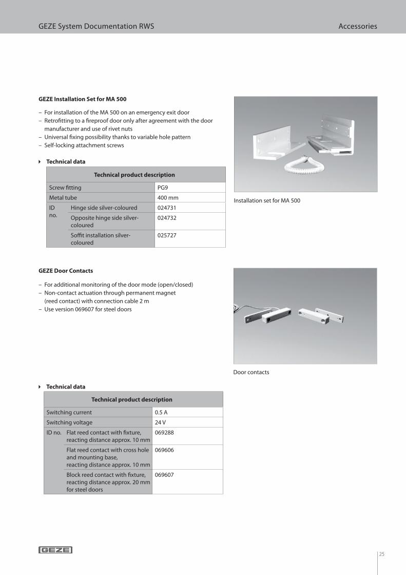
GEZE Installation Set for MA 500
Technical product description
Screw ! tting PG9
Metal tube 400 mm
ID no.
Hinge side silver-coloured 024731
Opposite hinge side silver-coloured
024732
So" t installation silver-coloured
025727
c Technical data
– For additional monitoring of the door mode (open/closed)
– Non-contact actuation through permanent magnet
(reed contact) with connection cable 2 m
– Use version 069607 for steel doors
GEZE Door Contacts
Technical product description
Switching current 0.5 A
Switching voltage 24 V
ID no. Flat reed contact with ! xture, reacting distance approx. 10 mm
069288
Flat reed contact with cross hole and mounting base, reacting distance approx. 10 mm
069606
Block reed contact with ! xture, reacting distance approx. 20 mm for steel doors
069607
– For installation of the MA 500 on an emergency exit door
– Retro! tting to a ! reproof door only after agreement with the door
manufacturer and use of rivet nuts
– Universal ! xing possibility thanks to variable hole pattern
– Self-locking attachment screws
Installation set for MA 500
Door contacts
26
GEZE System Documentation RWS Accessories
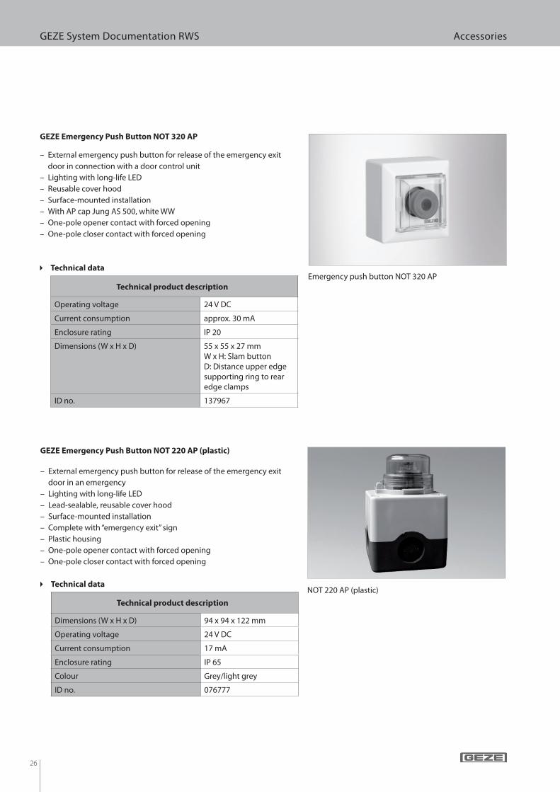
NOT 220 AP (plastic)
GEZE Emergency Push Button NOT 220 AP (plastic)
Technical product description
Dimensions (W x H x D) 94 x 94 x 122 mm
Operating voltage 24 V DC
Current consumption 17 mA
Enclosure rating IP 65
Colour Grey/light grey
ID no. 076777
c Technical data
– External emergency push button for release of the emergency exit
door in an emergency
– Lighting with long-life LED
– Lead-sealable, reusable cover hood
– Surface-mounted installation
– Complete with “emergency exit” sign
– Plastic housing
– One-pole opener contact with forced opening
– One-pole closer contact with forced opening
– External emergency push button for release of the emergency exit
door in connection with a door control unit
– Lighting with long-life LED
– Reusable cover hood
– Surface-mounted installation
– With AP cap Jung AS 500, white WW
– One-pole opener contact with forced opening
– One-pole closer contact with forced opening
Emergency push button NOT 320 AP
GEZE Emergency Push Button NOT 320 AP
Technical product description
Operating voltage 24 V DC
Current consumption approx. 30 mA
Enclosure rating IP 20
Dimensions (W x H x D) 55 x 55 x 27 mmW x H: Slam buttonD: Distance upper edge supporting ring to rear edge clamps
ID no. 137967
c Technical data
27
GEZE System Documentation RWS Accessories
c Technical data
– External emergency push button for release of the
emergency exit door in connection with a door control unit
– Lighting with long-life LED
– Reusable cover hood
– Flush-mounted installation
– One-pole opener contact
– One-pole closer contact
– Note: The frame must be ordered separately.
Emergency push button NOT 320 UP with frame
GEZE Emergency Push Button NOT 320 UP
c Technical data
Technical product description
Dimensions (W x H x D) 55 x 55 x 27 mmW x H: Slam buttonD: Distance upper edge supporting ring to rear edge clamps
Operating voltage 24 V DC
Current consumption approx. 30 mA
Enclosure rating IP 20
ID no. 136571 Delivered without frame
– Labelling of all emergency push buttons
– Self-adhesive and ! uorescent in accordance with DIN 4844-2
GEZE signs for emergency push button
Technical product description
Dimensions (W x H x D) 72 x 72 mm
ID no. Arrow upwards 088090
Arrow downwards 084992
Arrow to the right 100025
Arrow to the left 100017
Signs for the emergency push button

28
GEZE System Documentation RWS Accessories
Key switch SCT 221
GEZE Key Switch SCT 221
Technical product description
Dimensions (W x H x D)
Flush-mounted version 75 x 75 x 61 mm
Surface-mounted version 75 x 75 x 50 mm
Enclosure rating IP 54
ID no. Flush-mounted version
with pro! le half cylinder 054245
without pro! le half cylinder
054240
Surface-mounted version
with pro! le half cylinder 054533
without pro! le half cylinder
054532
c Technical data
– External key switch for authorised door passage by actuating the short-
term release function by key
– Connection to all door control units
– Surface-mounted or " ush-mounted installation
– With or without pro! le half cylinder
– Metal housing
– One-sided switching operation
– One-pole closer
– Zamak " ush-mounted box 50 mm deep included in the scope of
supply
– GEZE surface-mounted ! xture for mounting the emergency exit route
sign
GEZE ! xture for emergency exit sign
Technical product description
ID no. 089361
c Technical data
– Flush-mounted unit suitable for switch ranges of the size 55 x 55 mm
– Variants: illuminated, non-illuminated
GEZE Emergency Exit Route Sign FWS
Technical product description
ID no. illuminated 130383
non-illuminated 130381
c Technical data
Fixture for emergency exit sign
29
GEZE System Documentation RWS Accessories
– External key switch for authorised door passage by actuating the short-
term release function by key
– Connection to all door control units
– Flush-mounted installation
– Complete with pro! le half cylinder in single frame
– One-pole reversible switch (2 closers)
– With pro! le half cylinder
Key switch SCT 220 UP, LS 990 stainless steel
GEZE Key Switch SCT 220 UP
Technical product description
Dimensions (W x H x D) 81 x 81 x 62.5 mm
Enclosure rating IP 20
ID no.
Jung AS 500 alpine white
115442
LS 990 stainless steel
094170
Gira E2 pure white
094012
c Technical data
– External operating element for connection to GEZE SecuLogic door
control units
– LED left: red/green 24 V DC displaying locked/unlocked
– LED right: yellow for 24 V DC for displaying alarm
– Connection via integrated terminal strip and RP 220
– Aluminium front plate
– Complete with pro! le half cylinder
– Surface-mounted or " ush-mounted installation
– Switching operating to both sides, one-pole (closer)
Key switch SCT 222 with LED display
GEZE Key Switch SCT 222 with LED display
Technical product description
Dimensions Flush-mounted version Front plate: 110 x 100 mm
Flush-mounted box: ap-prox. 70 x 80 x 45 mm
Surface-mounted (W x H x D)
70 x 80 x 45 mm
Enclosure rating IP 54
ID no.
with pro! le half cylinder
Flush-mounted version
100065
Surface-mounted version
100064
c Technical data
30
GEZE System Documentation RWS Accessories
Key switch SCT 320
GEZE Key Switch SCT 320
Technical product description
Dimensions (W x H x D) 55 x 55 x 41 mm W x H: CoverD: Distance upper edge supporting ring to at-tached clamp
Operating voltage 24 V DC (±10 %)
Enclosure rating IP 20
ID no. white GIRA E2 130370
anthracite 132278
pure white Jung AS 500 131984
c Technical data
– External signal horn for acoustic alarm indication
– Connection possibility to all door control units
– Surface-mounted or " ush-mounted installation
– 26 settings for signal tone
Signal horn SLH 220
GEZE Signal Horn SLH 220
– Key switch with sabotage transmission
Technical product description
Dimensions Flush-mounted version 81 x 81 x 62.5 mm
Surface-mounted (Ø x H) 111 x 25,5 mm
Operating voltage 10-28 V DC
Current consumption 16 mA
Enclosure rating Flush-mounted version IP 20
Surface-mounted
version
IP 54
ID no. Flush-
mounted
version
Jung alpine white 091436
stainless
steel
091437
Surface-mounted version 072112
c Technical data
31
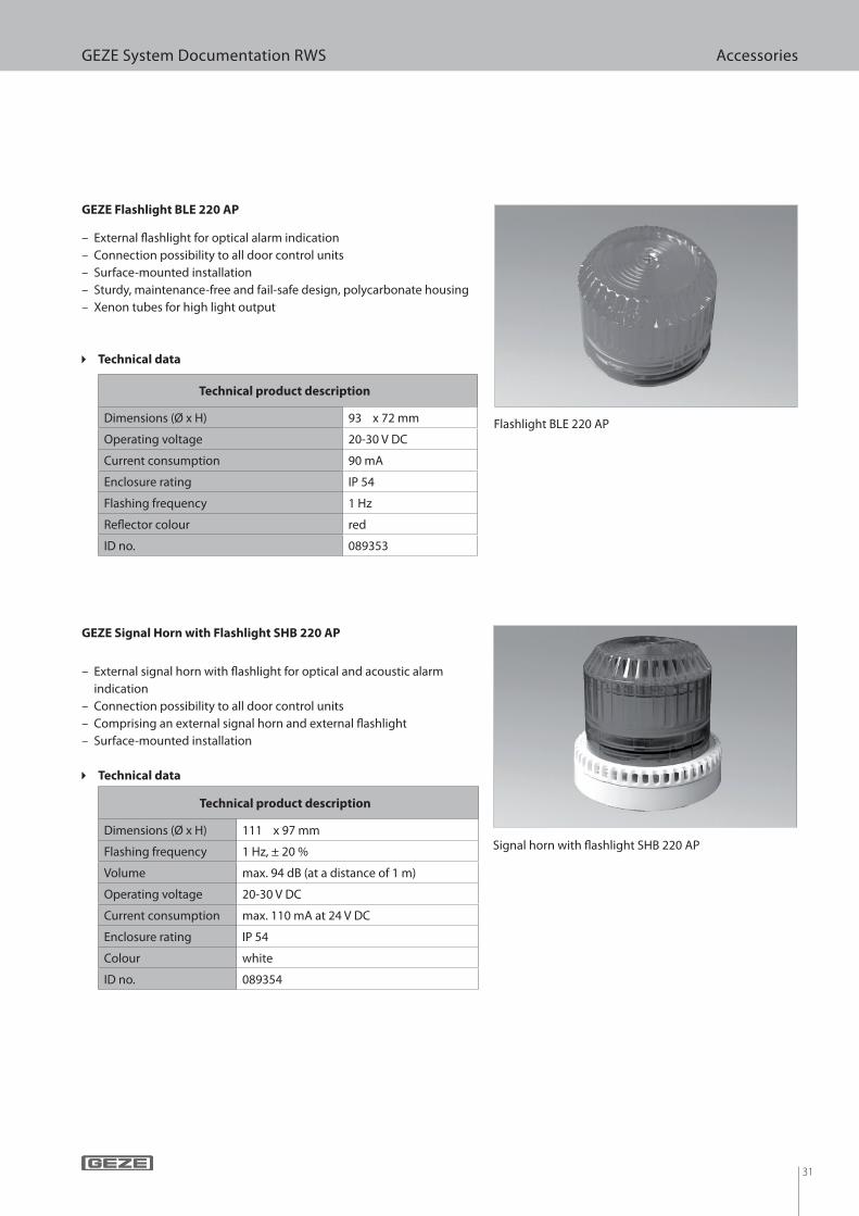
GEZE System Documentation RWS Accessories
– External ! ashlight for optical alarm indication
– Connection possibility to all door control units
– Surface-mounted installation
– Sturdy, maintenance-free and fail-safe design, polycarbonate housing
– Xenon tubes for high light output
Flashlight BLE 220 AP
GEZE Flashlight BLE 220 AP
Technical product description
Dimensions (Ø x H) 93 x 72 mm
Operating voltage 20-30 V DC
Current consumption 90 mA
Enclosure rating IP 54
Flashing frequency 1 Hz
Re! ector colour red
ID no. 089353
c Technical data
Signal horn with ! ashlight SHB 220 AP
GEZE Signal Horn with Flashlight SHB 220 AP
Technical product description
Dimensions (Ø x H) 111 x 97 mm
Flashing frequency 1 Hz, ± 20 %
Volume max. 94 dB (at a distance of 1 m)
Operating voltage 20-30 V DC
Current consumption max. 110 mA at 24 V DC
Enclosure rating IP 54
Colour white
ID no. 089354
c Technical data
– External signal horn with ! ashlight for optical and acoustic alarm
indication
– Connection possibility to all door control units
– Comprising an external signal horn and external ! ashlight
– Surface-mounted installation
32
GEZE System Documentation RWS Accessories
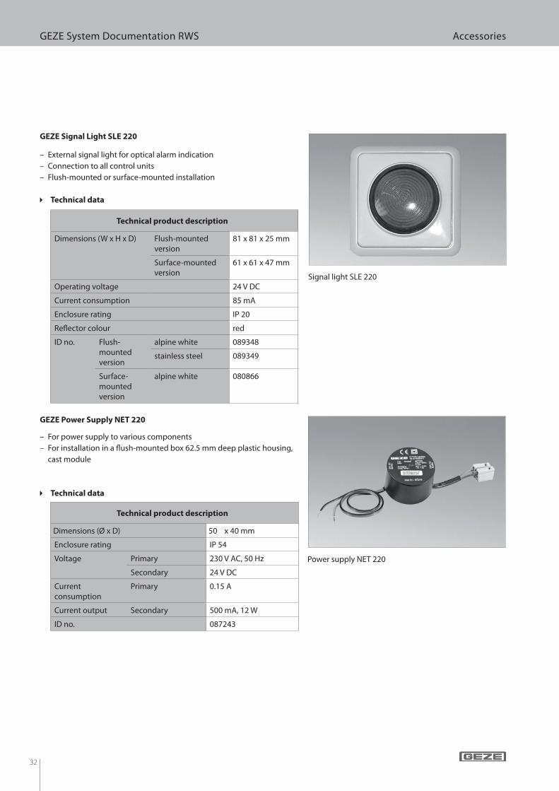
– External signal light for optical alarm indication
– Connection to all control units
– Flush-mounted or surface-mounted installation
Signal light SLE 220
GEZE Signal Light SLE 220
c Technical data
– For power supply to various components
– For installation in a ! ush-mounted box 62.5 mm deep plastic housing,
cast module
Power supply NET 220
GEZE Power Supply NET 220
Technical product description
Dimensions (Ø x D) 50 x 40 mm
Enclosure rating IP 54
Voltage Primary 230 V AC, 50 Hz
Secondary 24 V DC
Current
consumption
Primary 0.15 A
Current output Secondary 500 mA, 12 W
ID no. 087243
c Technical data
Technical product description
Dimensions (W x H x D) Flush-mounted
version
81 x 81 x 25 mm
Surface-mounted
version
61 x 61 x 47 mm
Operating voltage 24 V DC
Current consumption 85 mA
Enclosure rating IP 20
Re! ector colour red
ID no. Flush-
mounted
version
alpine white 089348
stainless steel 089349
Surface-
mounted
version
alpine white 080866
33
GEZE System Documentation RWS Accessories
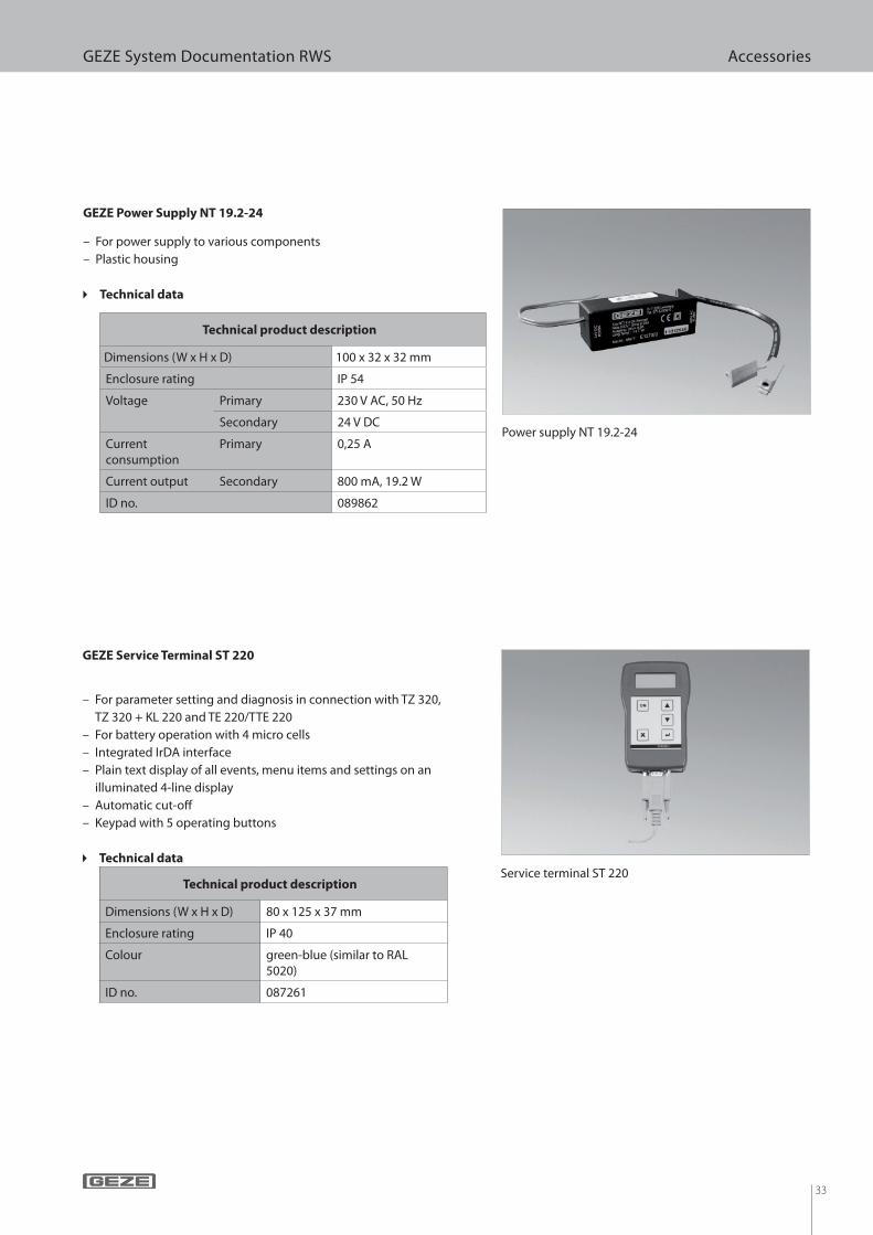
Power supply NT 19.2-24
GEZE Power Supply NT 19.2-24
c Technical data
– For parameter setting and diagnosis in connection with TZ 320,
TZ 320 + KL 220 and TE 220/TTE 220
– For battery operation with 4 micro cells
– Integrated IrDA interface
– Plain text display of all events, menu items and settings on an
illuminated 4-line display
– Automatic cut-o!
– Keypad with 5 operating buttons
Service terminal ST 220
GEZE Service Terminal ST 220
c Technical data
– For power supply to various components
– Plastic housing
Technical product description
Dimensions (W x H x D) 80 x 125 x 37 mm
Enclosure rating IP 40
Colour green-blue (similar to RAL 5020)
ID no. 087261
Technical product description
Dimensions (W x H x D) 100 x 32 x 32 mm
Enclosure rating IP 54
Voltage Primary 230 V AC, 50 Hz
Secondary 24 V DC
Current consumption
Primary 0,25 A
Current output Secondary 800 mA, 19.2 W
ID no. 089862
34
GEZE System Documentation RWS Accessories
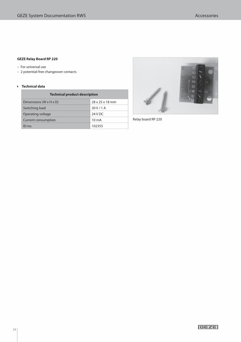
Relay board RP 220
– For universal use
– 2 potential-free changeover contacts
GEZE Relay Board RP 220
Technical product description
Dimensions (W x H x D) 28 x 25 x 18 mm
Switching load 30 V / 1 A
Operating voltage 24 V DC
Current consumption 10 mA
ID no. 102355
c Technical data

35
GEZE System Documentation RWS Dimensional drawings
31
.5
19
7
8877
Mounting plate
Door control unit TZ 300 AP
Speci! cations in mm
Dimensional drawings
Door control unit TZ 300 AP with emergency push button

36
GEZE System Documentation RWS Dimensional drawings
55 37
55
Door control unit TZ 300 UP
Door control unit TZ 300 UP
Speci! cations in mm

37
GEZE System Documentation RWS Dimensional drawings
77 88
19
73
1.5
19
7
8877
Door control unit TZ 322 AP
Door control unit TZ 322 AP
Door control unit TZ 320 AP with emergency push button
Door control unit TZ 320 AP with emergency push button
Mounting plate
Mounting plate
Speci! cations in mm
38
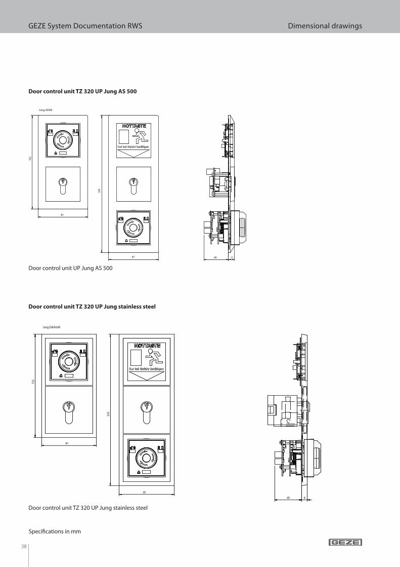
GEZE System Documentation RWS Dimensional drawings
Jung, AS500
15
2
81
81
22
3
49 11
Jung, Edelstahl
81
81
15
2
22
3
49 8
Door control unit TZ 320 UP Jung AS 500
Door control unit UP Jung AS 500
Speci! cations in mm
Door control unit TZ 320 UP Jung stainless steel
Door control unit TZ 320 UP Jung stainless steel
39
GEZE System Documentation RWS Dimensional drawings
22
.4
14
25 1
9 12
200
43
33
9
27.75 38134.25 21.5
91.5 49
33 126053
7 186
43
220
42
4.9
106.5 64.549
10 200
42.75 43.25134
21.7 3
20
30
20
30
3
48
35
15
Emergency exit door opener with short � at strike plate (diagram shows DIN left, DIN right is mirror-inverted)
Emergency exit door opener with short ! at strike plate (diagram shows DIN left, DIN right is mirror-inverted)
Emergency exit door opener with short angled strike plate (diagram shows DIN left, DIN right is mirror-inverted)
Emergency exit door opener with short angled strike plate (diagram shows DIN left, DIN right is mirror-inverted)
Speci" cations in mm
40
GEZE System Documentation RWS Dimensional drawings
18
11
0
64
ø5.5
ø10.4
51
4
39
32
337
79
6
324
12
17
12
24
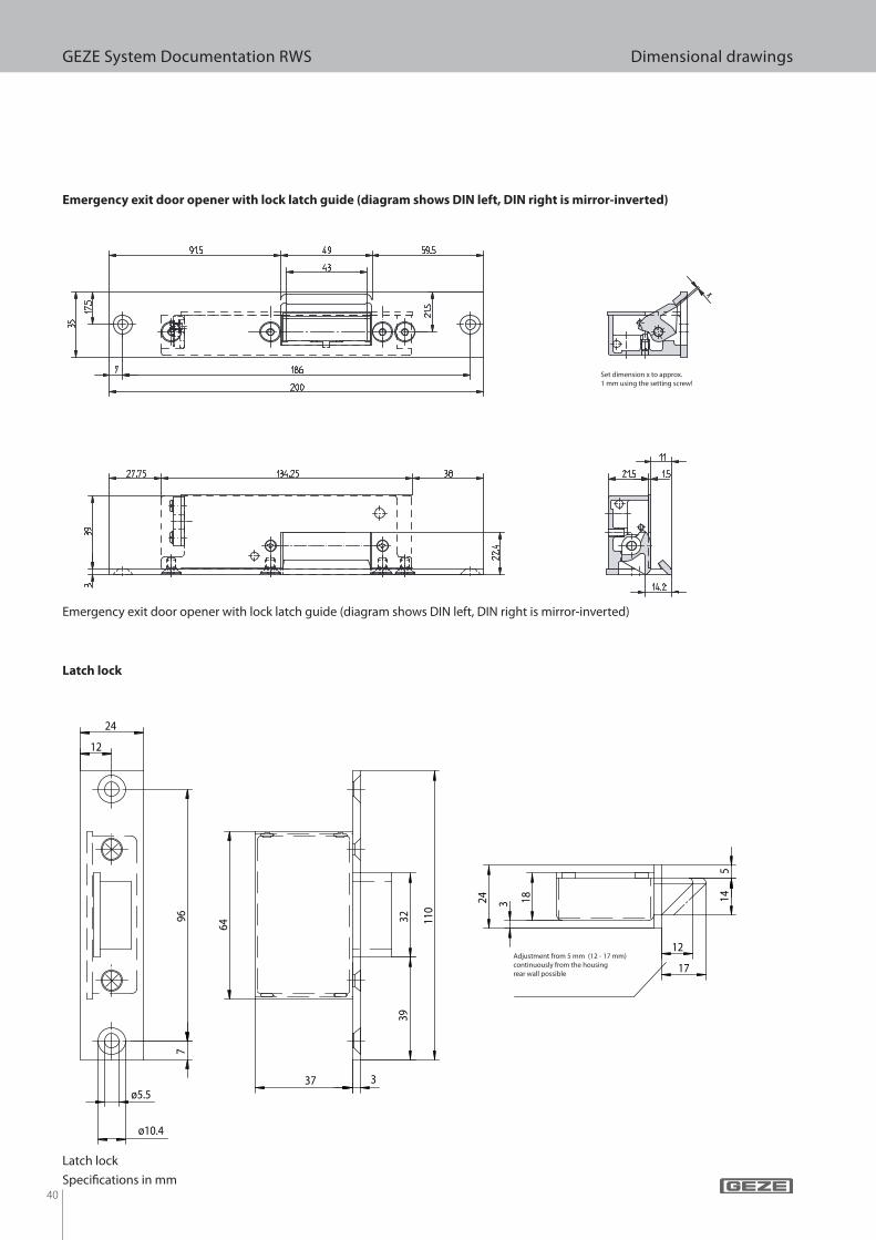
Emergency exit door opener with lock latch guide (diagram shows DIN left, DIN right is mirror-inverted)
Emergency exit door opener with lock latch guide (diagram shows DIN left, DIN right is mirror-inverted)
Speci! cations in mm
Latch lock
Latch lock
Set dimension x to approx. 1 mm using the setting screw!
Adjustment from 5 mm (12 - 17 mm) continuously from the housing rear wall possible
41
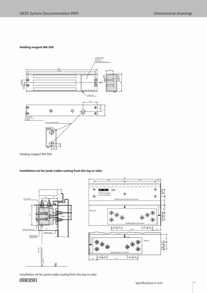
GEZE System Documentation RWS Dimensional drawings
A
Ansicht "A"
12
19
41
66
266
26
52
254`0.1
20
`0.1
ø6
.4
ø1
0.3
27
10
`0.1
M6x20
M6x20
RWS
FFB
72
75
88
17
88
270
26 33
29
26
30155
202020 20
30 155
2020 20 20
26
26
29
33
29
26
20115 115
Holding magnet MA 500
Holding magnet MA 500
Installation set for jamb (cable routing from the top or side)
Installation set for jamb (cable routing from the top or side)
Diagram sticker 21206-2-0374 applied to the inside of the cover
E-connection (thread)
View “A”
Type plate21206-2-027929535
Status LED
Attachment bracket on the jamb
Drilling templateJamb installation
DIN right
Holding plate on the door
DIN left
Holding plate on the door
Lintel
Holding plate
Lock washer
Attachment bracket
Magnet with
counterplate
min
2m
cle
ar p
assa
ge
hei
gh
t
req
uir
ed
Do
or
DIN
left
Do
or
DIN
rig
ht
CA
UTI
ON
Jam
b lo
ck s
ide
Jam
b lo
ck
sid
e
Speci! cations in mm
42
GEZE System Documentation RWS Dimensional drawings
RWS
Mat.Nr. 25719
FFB
M6x20
M6x20
88
17
15
4
270
14
6
16
17
71
33
26
26
24
33
20115 115
3020 20 75 20 20
26
26
57
M6x20
M6x20
RWS
14
6
16
24
23
37
330
88
17
270
24
26
33
115 115
95 95
75 75
115115
26
26
33
24
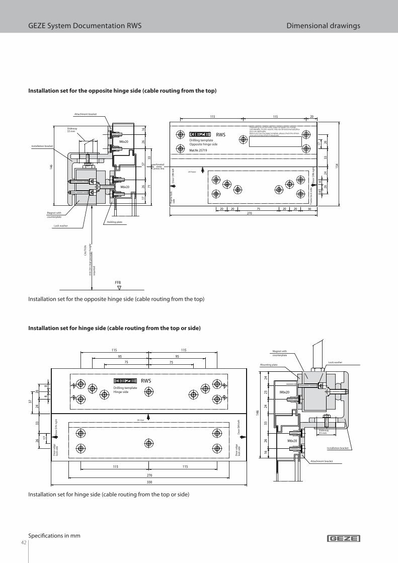
Installation set for the opposite hinge side (cable routing from the top)
Installation set for the opposite hinge side (cable routing from the top)
Speci! cations in mm
Installation set for hinge side (cable routing from the top or side)
Installation set for hinge side (cable routing from the top or side)
Drilling templateOpposite hinge side
Depending on air humidity, paper template can change considerably. For this reason, only our dimensional speci! ca-tions are applicable.Before you use the paper template, please check the dimen-sions and correct them if necessary.
Holding plate
Lock washer
Attachment bracket
Magnet with
counterplate
min
2m
cle
ar p
assa
ge
hei
gh
t
req
uir
ed
Do
or
DIN
left
Do
or
DIN
rig
ht
CA
UTI
ON
Fram
e lo
ck s
ide
Fram
e lo
ck
sid
e
Installation bracket
Slideway33 mm
perforated
Centre lineUK frame
Drilling templateHinge side
Lock washer
Attachment bracket
Magnet with
counterplate
Do
or
DIN
rig
ht
Do
or
DIN
left
Do
or
edg
e lo
ck s
ide
Do
or
edg
e lo
ck s
ide
Mounting plate
Slideway33 mm
OK door
Installation bracket

43
GEZE System Documentation RWS Dimensional drawings
M3
10
15
23
ø8
1.7
10
15
23
ø8
1.72
757
15
23
.3
45
10.3
18
ø3.2
ø5.8
ø3.2
ø5.5
ø3.2
ø5.5
23
2.5
30
2.2
5.2
60
ø3.2
9 9
64
ø3.2
94
4
60
ø3.2
52
45
2
68
2
4.5
9
2
12
9
18
4.5
9
Round reed contact with � xture (reacting distance 5 mm)
Round reed contact with ! xture (reacting distance 5 mm)
Flat reed contact with � xture (reacting distance 10 mm)
Flat reed contact with ! xture (reacting distance 10 mm)
Connection cable
approx. 2 m long
Magnetic housing
Reacting distance:
approx. 5 mm
Installation ! xtureContact housing
Connection cable
approx. 2 m long
Reacting distance:
approx. 10 mm
FixtureMagnet Flat reed contact
Speci! cations in mm

44
GEZE System Documentation RWS Dimensional drawings
60
ø3.2
60
45
2
45
2
5.5
11
4.5
9
4.5
9
4
4
65
14
ø4
.3
65
14
ø4
.3
54
5.5
54
6.5
13
6.5
13
Speci! cations in mm
Flat reed contact with cross hole and mounting base (reacting distance approx. 10 mm)
Flat reed contact with cross hole and mounting base (reacting distance approx. 10 mm)
Block reed contact with mounting base for steel doors (reacting distance 20 mm)
Block reed contact with mounting base for steel doors (reacting distance 20 mm)
Connection cable
approx. 2 m long
Reacting distance:
approx. 10 mm
Scope of supply:
1 " at reed contact
1 magnet
12 mounting bases
MagnetFlat reed contact with cross hole
Connection cable
approx. 2 m long
Block magnet with mounting base
Reacting distance:
approx. 20 mm
Scope of supply:
1 block magnet
1 block reed contact
6 mounting bases
Block reed contact

45
GEZE System Documentation RWS Dimensional drawings
3
94
94
41
94
94
7950
79
50
47
47
3981
122
ø22.5
3
21206-2-035076799
2-
3-
1-
21206-6-085224249
21206-1-011424463
21206-1-101876778
1-
3-
2-
21206-2-029169449
2
Emergency push button 220 AP (plastic housing IP 65)
Emergency push button 220 AP (plastic housing IP 65)
Bottom part of housing21206-1-1018
7 x M16/20 break-out
Top part of housing21206-1-1018
Speci! cations in mm
46
GEZE System Documentation RWS Cable diagrams
3 2 1
71mm
190.00
71.00
71.00
24.50
11.7511.75
30.00
23.00
50.00
50.00
25.007.50
30.005.50
22.00
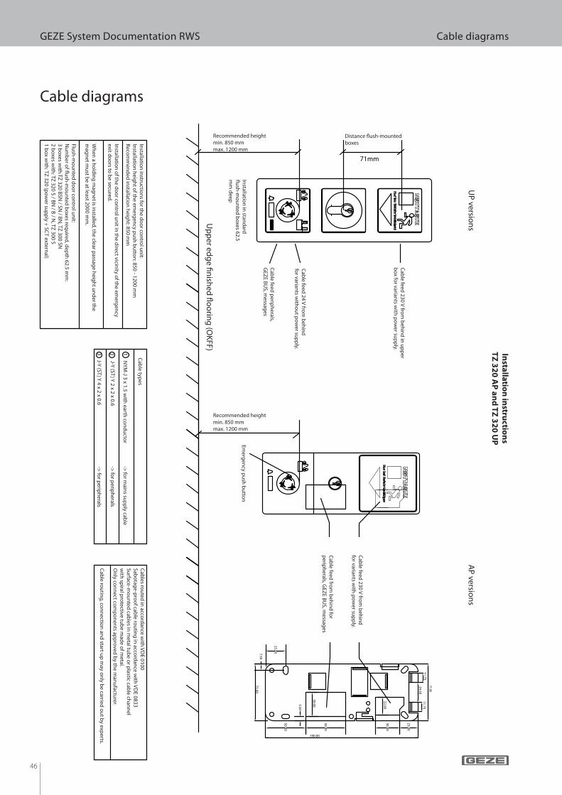
Cable diagrams
Insta
llatio
n in
structio
ns
TZ
32
0 A
P a
nd
TZ
32
0 U
P
UP
version
sA
P versio
ns
NY
M-J 3 x 1.5 w
ith earth
con
du
ctor ->
for m
ains su
pp
ly cable
J-Y (ST
) Y 2 x 2 x 0.6 ->
for p
eriph
erals
J-Y (ST
) Y 4 x 2 x 0.6 ->
for p
eriph
erals
Cab
le types
Installatio
n in
stand
ard
! ush
-mo
un
ted
bo
xes 6
2.5
mm
de
ep
Distance ! ush-mounted
boxes
Ca
ble
fee
d 2
4 V
from
be
hin
d
for v
aria
nts w
itho
ut p
ow
er su
pp
ly.
Ca
ble
fee
d p
erip
he
rals,
GE
ZE
BU
S, m
essa
ge
s
Ca
ble
fee
d 2
30
V fro
m b
eh
ind
in u
pp
er
bo
x for v
aria
nts w
ith p
ow
er su
pp
ly.
Recommended height
min. 850 mm
max. 1200 mm
Em
erg
en
cy p
ush
bu
tton
Ca
ble
fee
d fro
m b
eh
ind
for
pe
riph
era
ls, GE
ZE
BU
S, m
essa
ge
s
Ca
ble
fee
d 2
30
V fro
m b
eh
ind
for v
aria
nts w
ith p
ow
er su
pp
ly.
Up
pe
r ed
ge
" nish
ed
! oo
ring
(OK
FF
)
Ca
ble
s rou
ted
in a
ccord
an
ce w
ith V
DE
01
00
Sa
bo
tag
e-p
roo
f cab
le ro
utin
g in
acco
rda
nce
with
VD
E 0
83
3
Su
rface
-mo
un
ted
cab
les in
me
tal tu
be
or p
lastic ca
ble
cha
nn
el
with
spira
l pro
tectiv
e tu
be
ma
de
of m
eta
l.
On
ly co
nn
ect co
mp
on
en
ts ap
pro
ve
d b
y th
e m
an
ufa
cture
r.
Ca
ble
rou
ting
, con
ne
ction
an
d sta
rt-up
ma
y o
nly
be
carrie
d o
ut b
y e
xpe
rts.
Insta
llatio
n in
structio
ns fo
r the
do
or co
ntro
l un
it:
Insta
llatio
n h
eig
ht o
f the
em
erg
en
cy p
ush
bu
tton
: 85
0 - 1
20
0 m
m
Re
com
me
nd
ed
insta
llatio
n h
eig
ht: 8
50
mm
Insta
llatio
n o
f the
do
or co
ntro
l un
it in th
e d
irect v
icinity
of th
e e
me
rge
ncy
exit d
oo
rs to b
e se
cure
d.
Wh
en
a h
old
ing
ma
gn
et is in
stalle
d, th
e cle
ar p
assa
ge
he
igh
t un
de
r the
ma
gn
et m
ust b
e a
t lea
st 20
00
mm
.
Flush
-mo
un
ted
do
or co
ntro
l un
it:
Nu
mb
er o
f ! ush
-mo
un
ted
bo
xes re
qu
ired
, de
pth
62
.5 m
m:
3 b
oxe
s with
TZ
32
0 B
SN
/ SN
/ BN
, TZ
30
0 S
N
2 b
oxe
s with
: TZ
32
0 S
/ BN
/ B / N
, TZ
30
0 S
1 b
ox w
ith: T
Z 3
20
(po
we
r sup
ply
+ S
CT
ex
tern
al)
Recommended height
min. 850 mm
max. 1200 mm
47
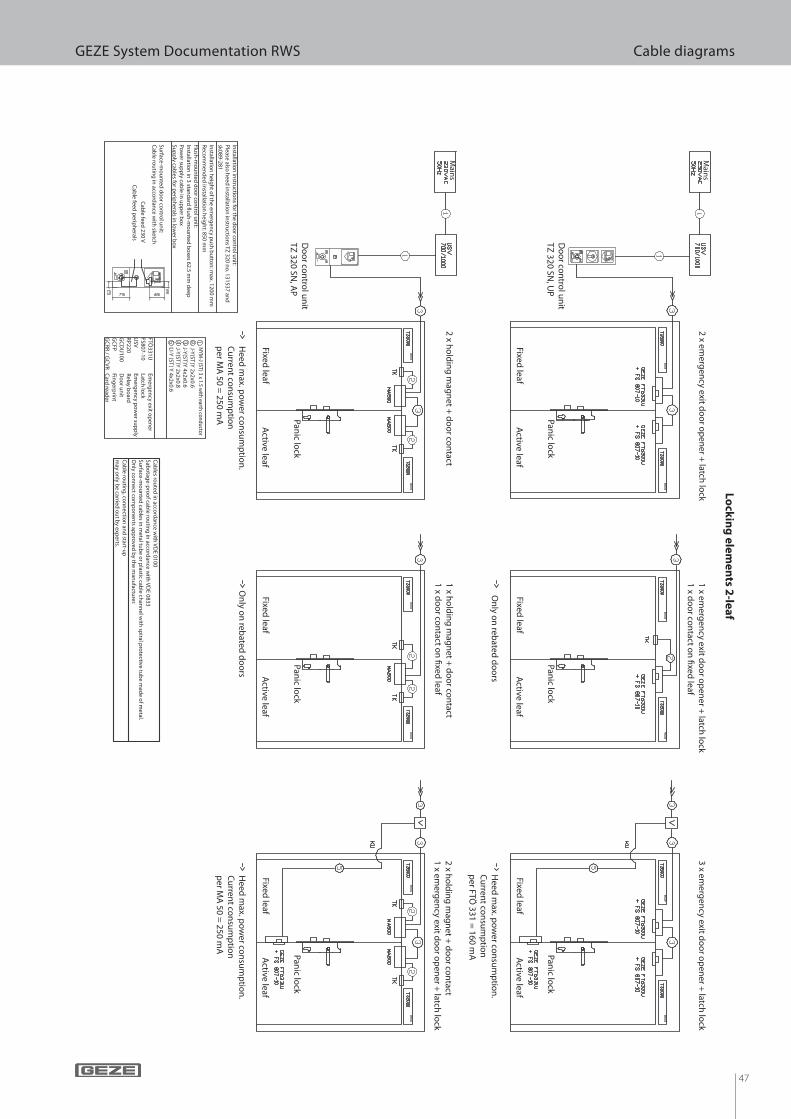
GEZE System Documentation RWS Cable diagrams
Active leaf
Fixed leaf
Panic lo
ck
Active leaf
Fixed leaf
Active leaf
Fixed leaf
Active leaf
Fixed leaf
Active leaf
Fixed leaf
Active leaf
Fixed leaf
Main
s
Main
s
Do
or co
ntro
l un
itTZ
320 SN, U
P
Do
or co
ntro
l un
itTZ
320 SN, A
P
2 x ho
ldin
g m
agn
et + d
oo
r con
tact1 x h
old
ing
mag
net +
do
or co
ntact
1 x do
or co
ntact o
n ! xed
leaf2 x h
old
ing
mag
net +
do
or co
ntact
1 x emerg
ency exit d
oo
r op
ener +
latch lo
ck
Heed
max. p
ow
er con
sum
ptio
n.
Cu
rrent co
nsu
mp
tion
per M
A 50 =
250 mA
On
ly on
rebated
do
ors
Heed
max. p
ow
er con
sum
ptio
n.
Cu
rrent co
nsu
mp
tion
p
er MA
50 = 250 m
A
Panic lo
ckPan
ic lock
Panic lo
ckPan
ic lock
Panic lo
ck
2 x emerg
ency exit d
oo
r op
ener +
latch lo
ck1 x em
ergen
cy exit do
or o
pen
er + latch
lock
1 x do
or co
ntact o
n ! xed
leaf3 x em
ergen
cy exit do
or o
pen
er + latch
lock
On
ly on
rebated
do
ors
Heed
max. p
ow
er con
sum
ptio
n.
Cu
rrent co
nsu
mp
tion
per FTÖ
331 = 160 m
A
Lo
ckin
g e
lem
en
ts 2-le
af
Installatio
n in
structio
ns fo
r the d
oo
r con
trol u
nit:
Please also
heed
installatio
n in
structio
ns TZ
320 no
. 131537 and
sk089-281
Flush
-mo
un
ted d
oo
r con
trol u
nit:
Installatio
n in
3 stand
ard # u
sh-m
ou
nted
bo
xes 62.5 mm
deep
Pow
er sup
ply cab
le in u
pp
er bo
xSu
pp
ly cables fo
r perip
herals in
low
er bo
x
Installatio
n h
eigh
t of th
e emerg
ency p
ush
bu
tton
: max. 1200 m
mR
ecom
men
ded
installatio
n h
eigh
t: 850 mm
Surface
-mo
un
ted d
oo
r con
trol u
nit:
Cab
le rou
ting
in acco
rdan
ce with
sketch
Cab
le feed 230 V
Cab
le feed p
eriph
erals
Cab
les rou
ted in
accord
ance w
ith V
DE 0100
Sabo
tage
-pro
of cab
le rou
ting
in acco
rdan
ce with
VD
E 0833Su
rface-m
ou
nted
cables in
metal tu
be o
r plastic cab
le chan
nel w
ith sp
iral pro
tective tub
e mad
e of m
etal.O
nly co
nn
ect com
po
nen
ts app
roved
by th
e man
ufactu
rer.
Cab
le rou
ting
, con
nectio
n an
d start-u
p
may o
nly b
e carried o
ut b
y experts.
NYM
-J (ST) 3 x 1.5 with earth conductor
J-Y(ST
)Y 2x2x0.6
J-Y(ST
)Y 4x2x0.6
J-Y(ST
)Y 2x2x0.8
FTÖ331U
Em
ergen
cy exit op
ener
FS807-10 Latch
lock
USV
Em
ergen
cy po
wer su
pp
lyR
P220
Relay b
oard
GC
DU
100 D
oo
r un
itG
CFP
Fin
gerp
rint
GC
RR
/ GC
VR
Card
reader
LI-Y (ST
) Y 4x2x0.6
48
GEZE System Documentation RWS Cable diagramsS
tan
da
rd
TZ
30
0 S
N, U
P
Main
s
Alarm
messag
eFlash
-lig
ht
Sign
alh
orn
or
or
or
Firealarmsystem
Timer
Access
con
trol/
interco
mK
ey sw
itch
with
d
isplay
Key
switch
Do
or co
ntro
l un
itPan
ic lock
Installatio
n in
structio
ns fo
r the d
oo
r con
trol u
nit:
Please also
heed
installatio
n in
structio
ns TZ
300 no
. 137351 an
d sk089-281.
Installatio
n h
eigh
t of th
e emerg
ency p
ush
bu
tton
: 850 - 1200mm
Reco
mm
end
ed in
stallation
heig
ht: 850 m
m
Flush
-mo
un
ted d
oo
r con
trol u
nit:
Insta
llatio
n in
3 sta
nd
ard
! ush
-mo
un
ted
bo
xes 6
2.5
mm
de
ep
Ma
ins su
pp
ly ca
ble
from
be
hin
d in
to th
e u
pp
er b
ox
Su
pp
ly ca
ble
s for p
erip
he
rals fro
m b
eh
ind
into
the
low
er b
ox
Su
rface
-mo
un
ted
do
or co
ntro
l un
it:C
ab
le ro
utin
g in
acco
rda
nce
with
sketch
Ca
ble
fee
d 2
30
V
Ca
ble
fee
d p
erip
he
rals
Ca
ble
s rou
ted
in a
ccord
an
ce w
ith V
DE
01
00
Sa
bo
tag
e-p
roo
f cab
le ro
utin
g in
acco
rda
nce
with
VD
E 0
83
3O
nly
con
ne
ct com
po
ne
nts a
pp
rov
ed
by
the
ma
nu
factu
rer
Po
ten
tial-fre
e co
nta
ct, op
en
er
Po
ten
tial-fre
e co
nta
ct, close
r, pe
rma
ne
nt co
nta
ctP
ote
ntia
l-free
con
tact, clo
ser, im
pu
lseV
olta
ge
sup
ply
via
do
or co
ntro
l un
it po
ssible
. N
ote
ma
ximu
m p
ow
er co
nsu
mp
tion
Po
ten
tial-fre
e co
nta
ct (30
V/1
A) fro
m th
e T
Z
FTö331U
Em
ergen
cy exit op
ener
FS807-10 Latch
lock
USV
Em
ergen
cy po
wer su
pp
lyR
P220
Relay b
oard
DC
DU
100 Sin
gle D
oo
r Un
itG
CD
U200
Do
or U
nit
GC
DU
Fin
gerp
rint
GC
RR
/ GC
VR
Card
reader
Do
or co
ntact
Ho
ldin
g m
agn
et
NY
M-J 3x1.5 w
ith earth
con
du
ctor
J-Y (ST
) Y 2x2x0.6
J-Y (ST
) Y 4x2x0.6
J-Y (ST
) Y 2x2x0.8
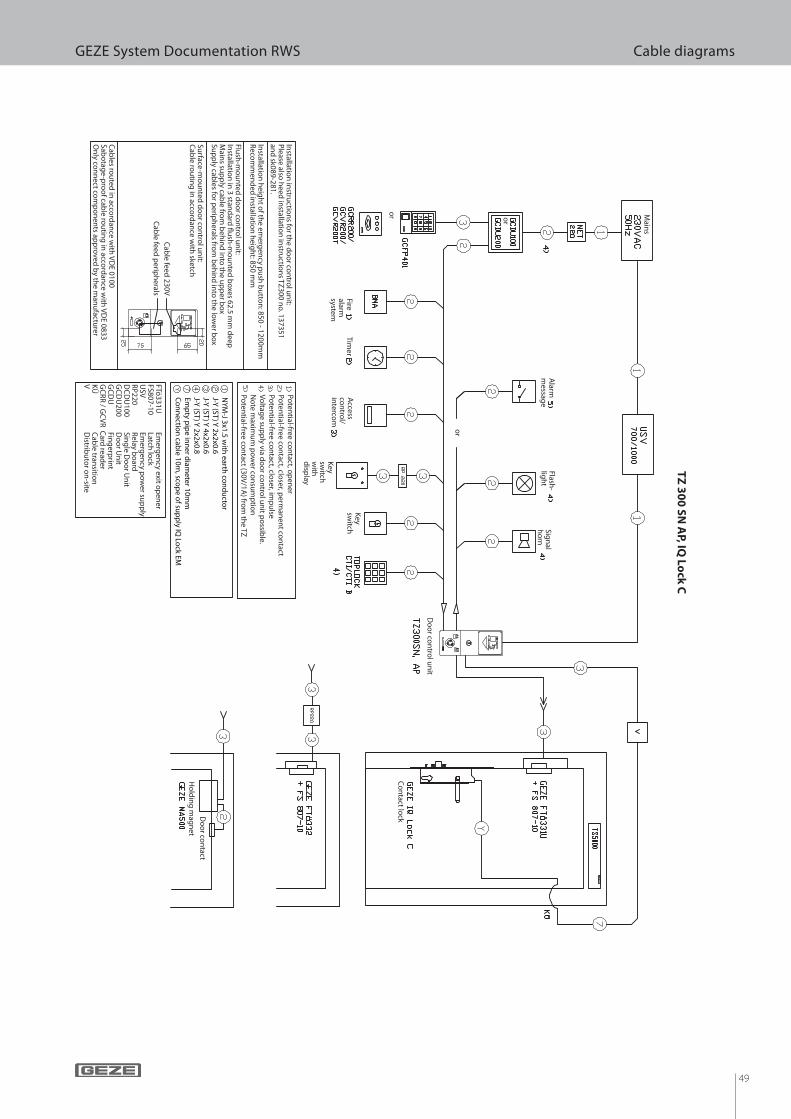
49
GEZE System Documentation RWS Cable diagrams
TZ
30
0 S
N A
P, IQ L
ock
C
Main
s
Alarm
messag
eFlash
-lig
ht
Sign
alh
orn
or
or
or
Firealarmsystem
Timer
Access
con
trol/
interco
mK
ey sw
itch
with
d
isplay
Key
switch
Do
or co
ntro
l un
it
Co
ntact lo
ck
Installatio
n in
structio
ns fo
r the d
oo
r con
trol u
nit:
Please also
heed
installatio
n in
structio
ns TZ
300 no
. 137351 an
d sk089-281.
Installatio
n h
eigh
t of th
e emerg
ency p
ush
bu
tton
: 850 - 1200mm
Reco
mm
end
ed in
stallation
heig
ht: 850 m
m
Flush
-mo
un
ted d
oo
r con
trol u
nit:
Insta
llatio
n in
3 sta
nd
ard
! ush
-mo
un
ted
bo
xes 6
2.5
mm
de
ep
Ma
ins su
pp
ly ca
ble
from
be
hin
d in
to th
e u
pp
er b
ox
Su
pp
ly ca
ble
s for p
erip
he
rals fro
m b
eh
ind
into
the
low
er b
ox
Su
rface
-mo
un
ted
do
or co
ntro
l un
it:C
ab
le ro
utin
g in
acco
rda
nce
with
sketch
Ca
ble
fee
d 2
30
V
Ca
ble
fee
d p
erip
he
rals
Ca
ble
s rou
ted
in a
ccord
an
ce w
ith V
DE
01
00
Sa
bo
tag
e-p
roo
f cab
le ro
utin
g in
acco
rda
nce
with
VD
E 0
83
3O
nly
con
ne
ct com
po
ne
nts a
pp
rov
ed
by
the
ma
nu
factu
rer
Po
ten
tial-fre
e co
nta
ct, op
en
er
Po
ten
tial-fre
e co
nta
ct, close
r, pe
rma
ne
nt co
nta
ctP
ote
ntia
l-free
con
tact, clo
ser, im
pu
lseV
olta
ge
sup
ply
via
do
or co
ntro
l un
it po
ssible
. N
ote
ma
ximu
m p
ow
er co
nsu
mp
tion
Po
ten
tial-fre
e co
nta
ct (30
V/1
A) fro
m th
e T
Z
FTö331U
Em
ergen
cy exit op
ener
FS807-10 Latch
lock
USV
Em
ergen
cy po
wer su
pp
lyR
P220
Relay b
oard
DC
DU
100 Sin
gle D
oo
r Un
itG
CD
U200
Do
or U
nit
GC
DU
Fin
gerp
rint
GC
RR
/ GC
VR
Card
reader
KÜ
Cab
le transitio
nV
Distrib
uto
r on
-site
Do
or co
ntact
Ho
ldin
g m
agn
et
NY
M-J 3x1.5 w
ith earth
con
du
ctor
J-Y (ST
) Y 2x2x0.6
J-Y (ST
) Y 4x2x0.6
J-Y (ST
) Y 2x2x0.8
Emp
ty pip
e inn
er diam
eter 10mm
Co
nn
ection
cable 10m
, scop
e of su
pp
ly IQ Lo
ck EM
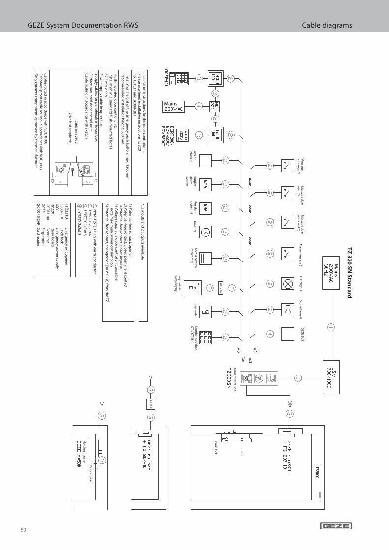
50
GEZE System Documentation RWS Cable diagrams
Sign
al ho
rn 4)
Flashlig
ht 4)
Alarm
messag
e 5)
1) Poten
tial-free con
tact, op
ener
2) Poten
tial-free con
tact, closer, p
erman
ent co
ntact
3) Poten
tial-free con
tact, closer, im
pu
lse4) V
oltag
e sup
ply via d
oo
r con
trol u
nit p
ossib
le, n
ote m
aximu
m p
ow
er con
sum
ptio
n5) Po
tential-free co
ntact, ch
ang
eover (30 V
/ 1 A) fro
m th
e TZ
NY
M-J (ST
) 3 x 1.5 with
earth co
nd
ucto
rJ-Y
(ST)Y
2x2x0.6J-Y
(ST)Y
4x2x0.6
Do
or co
ntact
Ho
ldin
g m
agn
et
Panic lo
ck
Fire alarm
system 1)
Timer 2)
Bu
rglar
alarm
system
Access co
ntro
l/In
tercom
3)
Key sw
itch
with
disp
lay
Key sw
itchLo
ck or
un
lock 3)
Main
s
Nu
mb
er cod
elock
CTI / C
TI B 4)
Do
or co
ntro
l un
it
GEZ
E BU
SM
essage
sabo
tage 5)
Messag
e do
or
op
en 5)
Messag
e do
or
un
locked
5)
J-Y(ST
)Y 2x2x0.8
*) 3 inp
uts an
d 2 o
utp
uts availab
le
FTÖ331U
Em
ergen
cy exit op
ener
FS807-10 Latch
lock
USV
Em
ergen
cy po
wer su
pp
lyR
P220
Relay b
oard
GC
DU
100 D
oo
r un
itG
CFP
Fin
gerp
rint
GC
RR
/ GC
VR
Card
reader
Installatio
n in
structio
ns fo
r the d
oo
r con
trol u
nit:
Please also
heed
installatio
n in
structio
ns TZ
320 n
o. 131537 an
d sk089-281
Flush
-mo
un
ted d
oo
r con
trol u
nit:
Insta
llatio
n in
3 sta
nd
ard
" ush
-mo
un
ted
bo
xes
62
.5 m
m d
ee
p
Po
we
r sup
ply
cab
le in
up
pe
r bo
x
Su
pp
ly ca
ble
s for p
erip
he
rals in
low
er b
ox
Insta
llatio
n h
eig
ht o
f the
em
erg
en
cy p
ush
bu
tton
: ma
x. 12
00
mm
Re
com
me
nd
ed
insta
llatio
n h
eig
ht: 8
50
mm
Su
rface
-mo
un
ted
do
or co
ntro
l un
it:
Ca
ble
rou
ting
in a
ccord
an
ce w
ith ske
tch
Ca
ble
s rou
ted
in a
ccord
an
ce w
ith V
DE
01
00
Sa
bo
tag
e-p
roo
f cab
le ro
utin
g in
acco
rda
nce
with
VD
E 0
83
3
On
ly co
nn
ect co
mp
on
en
ts ap
pro
ve
d b
y th
e m
an
ufa
cture
r.
Ca
ble
fee
d 2
30
V
Ca
ble
fee
d p
erip
he
rals
Mains
TZ
32
0 S
N S
tan
da
rd
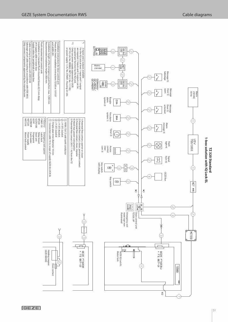
51
GEZE System Documentation RWS Cable diagramsT
Z 3
20
Sta
nd
ard
1-b
ox
solu
tion
with
IQ L
ock
EL
*) 3 in
pu
ts and
2 ou
tpu
ts available
Fo
r the IQ
Lock at least 1 in
pu
t and
1 ou
tpu
t
are requ
ired. 2 in
pu
ts and
2 ou
tpu
ts can b
e
occu
pied
per fu
nctio
n b
y the IQ
Lock.
**) O
nly u
se po
wer su
pp
ly app
roved
by G
EZE.
N
T19.2-24, No
. 089862, NET 24-5, N
o. 111182,
o
r po
wer su
pp
ly 1.3 A, N
o. 078401. H
ou
sing
on
-site.
Installatio
n in
structio
ns fo
r do
or co
ntro
l un
it:P
lease also h
eed in
stallation
instru
ction
s TZ320 o
r 131537 an
d sk089-281.
Installatio
n h
eigh
t of th
e emerg
ency p
ush
bu
tton
: max. 1200 m
mR
ecom
men
ded
installatio
n h
eigh
t: 850 mm
Flush
-mo
un
ted d
oo
r con
trol u
nit:
Insta
llatio
n in
2 sta
nd
ard
! ush
-mo
un
ted
bo
xes 6
2.5
mm
de
ep
24
V su
pp
ly ca
ble
in lo
we
r bo
xS
up
ply
cab
les fo
r pe
riph
era
ls in lo
we
r bo
x
Ca
ble
rou
ting
in a
ccord
an
ce w
ith V
DE
01
00
Sa
bo
tag
e-p
roo
f cab
le ro
utin
g in
acco
rda
nce
with
VD
E 0
83
3.
On
ly co
nn
ect co
mp
on
en
ts ap
pro
ve
d b
y th
e m
an
ufa
cture
r.
1) P
ote
ntia
l-free
con
tact, o
pe
ne
r or clo
ser
2) P
ote
ntia
l-free
con
tact, clo
ser, p
erm
an
en
t con
tact
3) P
ote
ntia
l-free
con
tact, clo
ser, im
pu
lse4
) He
ed
ma
x. po
we
r con
sum
ptio
n5
) Po
ten
tial-fre
e co
nta
ct (30
V / 1
A) fro
m th
e T
Z
' NY
M-J 3
x1.5
with
ea
rth co
nd
ucto
r
' J-Y (S
T) 2
x2x0
.6
' J-Y (S
T) 4
x2x0
.6
' J-Y (S
T) 2
x2x0
.8
' Em
pty
pip
e in
ne
r dia
me
ter 1
0 m
m
Co
nn
ectio
n ca
ble
10
m, sco
pe
of su
pp
ly G
EZ
E IQ
LOC
K E
L
FTÖ331U
Em
ergen
cy exit op
ener
FS807-10 Latch
lock
RP
220 R
elay bo
ardG
CD
U100
Do
or u
nit
GC
FP
Fing
erprin
tG
CR
R/V
R
Card
reader
NET220
Pow
er sup
ply
MST210
Mo
tor lo
ck con
trol
Main
s230 VA
C50 H
z
Messag
e 5) Sab
otag
e
Messag
e D
oo
r 5) o
pen
Messag
e D
oo
r 5) u
nlo
ckedA
larmm
essage 5)
Flash-
ligh
t 4)Sig
nal
ho
rn 4)
GEZ
E Bu
s
Bu
rglar
alarmsystem
2)
Fire alarmsystem
1)
Timer 2)
Access
con
trol
inter-
com
3)K
ey switch
w
ith d
isplay
Key sw
itch
Do
or co
ntro
l un
it TZ
320, UP
Emerg
ency exit
rou
te sign
no
n-
illum
inated
GEZ
E IQ Lo
ck EL M
oto
r lock
Do
or co
ntact
Ho
ldin
g m
agn
etG
EZE M
A500
Mains230 VAC
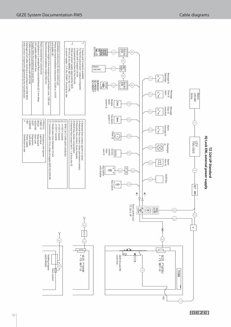
52
GEZE System Documentation RWS Cable diagramsT
Z 3
20
UP
Sta
nd
ard
IQ L
ock
EM
, ex
tern
al p
ow
er su
pp
ly
Messag
e 5) Sab
otag
e
Messag
e D
oo
r 5) o
pen
Messag
e D
oo
r 5) u
nlo
ckedA
larmm
essage 5)
Flashlig
ht
4)
Sign
al h
orn
4) G
EZE B
us
Bu
rglar
alarmsystem
2)
Fire alarmsystem
1)
Timer 2)
Access
con
trol
inter-
com
3)K
ey switch
w
ith d
isplay
Key sw
itch
Mains230 VAC
Main
s230 VA
C50 H
z
Do
or co
ntact
Ho
ldin
g m
agn
etG
EZE M
A500
Do
or co
ntro
l un
it TZ
320 S, UP
GEZ
E IQ Lo
ck EMLever lo
ck
*) 3 in
pu
ts and
2 ou
tpu
ts available
Fo
r the IQ
Lock at least 1 o
utp
ut is req
uired
.
2 inp
uts an
d 2 o
utp
uts can
be
o
ccup
ied p
er fun
ction
by th
e IQ Lo
ck.**)
On
ly use p
ow
er sup
ply ap
pro
ved b
y GEZ
E.
NT19.2-24, N
o. 089862, N
ET 24-5, No
. 111182,
or p
ow
er sup
ply 1.3 A
, No
. 078401. Ho
usin
g o
n-site.
Installatio
n in
structio
ns fo
r do
or co
ntro
l un
it:P
lease also h
eed in
stallation
instru
ction
s TZ320 o
r 131537 an
d sk089-281.
Installatio
n h
eigh
t of th
e emerg
ency p
ush
bu
tton
: max. 1200 m
mR
ecom
men
ded
installatio
n h
eigh
t: 850 mm
Flush
-mo
un
ted d
oo
r con
trol u
nit:
Insta
llatio
n in
2 sta
nd
ard
! ush
-mo
un
ted
bo
xes 6
2.5
mm
de
ep
24
V su
pp
ly ca
ble
in lo
we
r bo
xS
up
ply
cab
les fo
r pe
riph
era
ls in lo
we
r bo
x
Ca
ble
rou
ting
in a
ccord
an
ce w
ith V
DE
01
00
Sa
bo
tag
e-p
roo
f cab
le ro
utin
g in
acco
rda
nce
with
VD
E 0
83
3.
On
ly co
nn
ect co
mp
on
en
ts ap
pro
ve
d b
y th
e m
an
ufa
cture
r.
1) P
ote
ntia
l-free
con
tact, o
pe
ne
r or clo
ser
2) P
ote
ntia
l-free
con
tact, clo
ser, p
erm
an
en
t con
tact
3) P
ote
ntia
l-free
con
tact, clo
ser, im
pu
lse4
) He
ed
ma
x. po
we
r con
sum
ptio
n5
) Po
ten
tial-fre
e co
nta
ct (30
V / 1
A) fro
m th
e T
Z
' NY
M-J 3
x1.5
with
ea
rth co
nd
ucto
r
' J-Y (S
T) Y
2x2
x0.6
' J-Y (S
T) Y
4x2
x0.6
' J-Y (S
T) Y
2x2
x0.8
' Em
pty
pip
e in
ne
r dia
me
ter 1
0 m
m
Co
nn
ectio
n ca
ble
10
m, sco
pe
of su
pp
ly G
EZ
E IQ
LOC
K E
M
FTÖ331U
Em
ergen
cy exit op
ener
FS807-10 Latch
lock
RP
220 R
elay bo
ardG
CD
U100
Do
or u
nit
GC
FP
Fing
erprin
tG
CR
R/V
R
Card
reader
NET
Po
wer su
pp
lyV
Distrib
uto
r on
-site
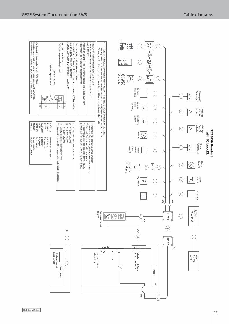
53
GEZE System Documentation RWS Cable diagrams
Bu
rglar
alarmsystem
2)
Fire alarmsystem
1)
Timer 2)
Access
con
trol
inter-
com
3)K
ey switch
w
ith d
isplay
Key sw
itchLo
ck or
un
lock 3)
Mains230 VAC
Messag
e 5) Sab
otag
e
Messag
e D
oo
r 5) o
pen
Messag
e D
oo
r 5) u
nlo
cked
Alarm
messag
e 5)
Flash-
ligh
t 4)Sig
nal
ho
rn 4)
GEZ
E Bu
s
TZ
32
0S
N K
om
fort
with
IQ L
ock
EL
Main
s230 VA
C50 H
z
GEZ
E IQ Lo
ck EL M
oto
r lock
Do
or co
ntact
Ho
ldin
g m
agn
etG
EZE M
A500
Do
or co
ntro
l un
it TZ
320S
Installatio
n in
structio
ns fo
r do
or co
ntro
l un
it:P
lease also h
eed in
stallation
instru
ction
s TZ320 o
r 131537 an
d sk089-281.
Installatio
n h
eigh
t of th
e emerg
ency p
ush
bu
tton
: max. 1200 m
mR
ecom
men
ded
installatio
n h
eigh
t: 850 mm
Flush
-mo
un
ted d
oo
r con
trol u
nit:
Insta
llatio
n in
3 sta
nd
ard
! ush
-mo
un
ted
bo
xes 6
2.5
mm
de
ep
Ma
ins su
pp
ly ca
ble
in u
pp
er b
ox
Su
pp
ly ca
ble
s for p
erip
he
rals in
low
er b
ox
Ca
ble
rou
ting
in a
ccord
an
ce w
ith V
DE
01
00
Sa
bo
tag
e-p
roo
f cab
le ro
utin
g in
acco
rda
nce
with
VD
E 0
83
3.
On
ly co
nn
ect co
mp
on
en
ts ap
pro
ve
d b
y th
e m
an
ufa
cture
r.
AP
do
or co
ntro
l un
it:
Ca
ble
rou
ting
acco
rdin
g to
sketch
Ca
ble
fee
d 2
30
V
Ca
ble
fee
d p
erip
he
rals
1) P
ote
ntia
l-free
con
tact, o
pe
ne
r or clo
ser
2) P
ote
ntia
l-free
con
tact, clo
ser, p
erm
an
en
t con
tact
3) P
ote
ntia
l-free
con
tact, clo
ser, im
pu
lse4
) He
ed
ma
x. po
we
r con
sum
ptio
n fo
r the
KL
22
05
) Po
ten
tial-fre
e co
nta
ct (30
V / 1
A) fro
m th
e T
Z
' NY
M-J 3
x1.5
with
ea
rth co
nd
ucto
r
' J-Y (S
T) Y
2x2
x0.6
' J-Y (S
T) Y
4x2
x0.6
' J-Y (S
T) Y
2x2
x0.8
' Em
pty
pip
e in
ne
r dia
me
ter 1
0 m
m
Co
nn
ectio
n ca
ble
10
m, sco
pe
of su
pp
ly G
EZ
E IQ
LOC
K E
M
FTÖ331U
Em
ergen
cy exit op
ener
FS807-10 Latch
lock
KL220
Termin
al bo
xG
CD
U100
Do
or u
nit
GC
FP
Fing
erprin
tG
CR
R/V
R
Card
reader
NET220
Pow
er sup
ply
MST210
Mo
tor lo
ck con
trol
*) Th
ere are 4 inp
uts an
d 6 o
utp
uts o
n th
e KL220. If th
e 3 inp
uts an
d/o
r 2 ou
tpu
ts of th
e TZ320
are req
uired
in ad
ditio
n, m
ore w
ires mu
st be p
lann
ed acco
rdin
gly b
etween
KL220 an
d TZ
320.
2 inp
uts an
d 2 o
utp
uts can
be o
ccup
ied b
y the IQ
Lock d
epen
din
g o
n th
e fun
ction
.
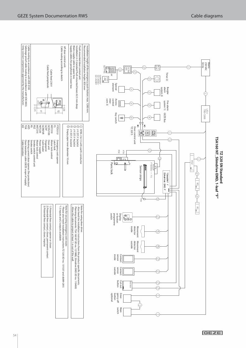
54
GEZE System Documentation RWS Cable diagrams
Installatio
n h
eigh
t of th
e emerg
ency p
ush
bu
tton
: max. 1200 m
mR
ecom
men
ded
installatio
n h
eigh
t: 850 mm
Flush
-mo
un
ted d
oo
r con
trol u
nit:
Insta
llatio
n in
3 sta
nd
ard
! ush
-mo
un
ted
bo
xes 6
2.5
mm
de
ep
Ma
ins su
pp
ly ca
ble
in u
pp
er b
ox
Su
pp
ly ca
ble
s for p
erip
he
rals in
low
er b
ox
Ca
ble
rou
ting
in a
ccord
an
ce w
ith V
DE
01
00
Sa
bo
tag
e-p
roo
f cab
le ro
utin
g in
acco
rda
nce
with
VD
E 0
83
3.
On
ly co
nn
ect co
mp
on
en
ts ap
pro
ve
d b
y th
e m
an
ufa
cture
r.
AP
do
or co
ntro
l un
it:
Ca
ble
rou
ting
acco
rdin
g to
sketch
Ca
ble
fee
d 2
30
V
Ca
ble
fee
d p
erip
he
rals
' NY
M-J 3
x1.5
with
ea
rth co
nd
ucto
r
' J-Y (S
T) Y
2x2
x0.6
' J-Y (S
T) Y
4x2
x0.6
' J-Y (S
T) Y
2x2
x0.8
' Em
pty
pip
e in
ne
r dia
me
ter 1
0 m
m
FTÖ331U
Em
ergen
cy exit op
ener
FS
Latch lo
ckM
ST210 M
oto
r lock co
ntro
lG
CD
U100
Do
or u
nit
GC
FP
Fing
erprin
tG
CR
R/V
R
Card
reader
NET220
Pow
er sup
ply
MST210
Mo
tor lo
ck con
trol
RSZ
Smo
ke switch
con
trol u
nit
RS
Sm
oke sw
itchA
TÖ
W
orkin
g cu
rrent d
oo
r op
ener (# re p
rotectio
n)
TÜK
Do
or tran
sition
cable (G
EZE sco
pe o
f sup
ply)
KÜ
Cab
le transitio
n
Main
s230 VA
C50 H
z
Do
or co
ntro
l un
itTZ
320 S
No
te for secu
ring
emerg
ency exit ro
ute:
- Please also
heed
installatio
n in
structio
ns TZ
320 (ID n
o. 131537 an
d sk089-281)
*) 3 inp
uts an
d 2 o
utp
uts availab
le
1) Poten
tial-free con
tact, op
ener o
r closer
2) Poten
tial-free con
tact, closer, p
erman
ent co
ntact
3) Poten
tial-free con
tact, closer, im
pu
lse
No
te for sw
ing
do
or d
rive:- A
lso h
eed th
e installatio
n in
structio
ns fro
m th
e pro
du
ct-speci# c d
ocu
men
ts. P
lann
ing
do
cum
ents: TSA
160 NT (ID
no
. 121988), Slimd
rive EMD
(ID n
o. 110450)
- Allo
w th
e cable to
pro
ject at least 1 m o
ut o
f the w
all.
GEZ
E Bu
s B
urg
lar alarmsystem
2)
Fire alarmsystem
1)Tim
er 2)
Access
con
trol
inter-
com
3)
Key sw
itchSp
ecial elem
ent
or
Panic lo
ck
Senso
r strips
Disp
lay o
r bu
tton
p
rog
ramm
e sw
itch
Mo
vemen
t d
etector
insid
e
Mo
vemen
t d
etector
ou
tside
Co
ntact
senso
rin
side
Co
ntact
senso
ro
utsid
e
Cu
t-ou
t b
utto
nEm
er-g
ency o
% b
utto
no
ptio
nal
Main
sw
itch
Clo
se do
or
TZ
32
0 S
N S
tan
da
rd
TS
A1
60
NT
_S
limd
rive
EM
D, 1
-lea
f “F”

55
GEZE System Documentation RWS Cable diagrams
Flush
-mo
un
ted d
oo
r con
trol u
nit:
Insta
llatio
n in
3 sta
nd
ard
! ush
-mo
un
ted
bo
xes 6
2.5
mm
de
ep
Po
we
r sup
ply
cab
le in
up
pe
r bo
x
Su
pp
ly ca
ble
s for p
erip
he
rals in
low
er b
ox
Insta
llatio
n h
eig
ht o
f the
em
erg
en
cy p
ush
bu
tton
: ma
x. 12
00
mm
Re
com
me
nd
ed
insta
llatio
n h
eig
ht: 8
50
mm
Su
rface
-mo
un
ted
do
or co
ntro
l un
it:
Ca
ble
rou
ting
in a
ccord
an
ce w
ith ske
tch
Ca
ble
s rou
ted
in a
ccord
an
ce w
ith V
DE
01
00
Sa
bo
tag
e-p
roo
f cab
le ro
utin
g in
acco
rda
nce
with
VD
E 0
83
3
On
ly co
nn
ect co
mp
on
en
ts ap
pro
ve
d b
y th
e m
an
ufa
cture
r.
Ca
ble
fee
d 2
30
V
Ca
ble
fee
d p
erip
he
rals
NY
M-J (S
T) 3
x 1.5
with
ea
rth co
nd
ucto
r
J-Y(S
T)Y
2x2
x0.6
J-Y(S
T)Y
4x2
x0.6
J-Y(S
T)Y
2x2
x0.8
No
te fo
r secu
ring
em
erg
en
cy e
xit rou
te:
- Ple
ase
also
he
ed
insta
llatio
n in
structio
ns T
Z 3
20
(ID n
o. 1
31
53
7 a
nd
sk08
9-2
81
)
*) 3 in
pu
ts an
d 2
ou
tpu
ts av
aila
ble
FTÖ331U
Em
ergen
cy exit op
ener
FS Latch
lock
RSK
B
olt sw
itch co
ntact
GC
DU
100 D
oo
r un
itG
CFP
Fin
gerp
rint
GC
RR
/ GC
VR
Card
reader
NET 220
Pow
er sup
ply
MST210
Mo
tor lo
ck con
trol
RSZ
Sm
oke sw
itch co
ntro
l un
itR
S Sm
oke sw
itchA
TÖ
Wo
rking
curren
t do
or o
pen
er (# re pro
tection
)TÜ
K
Do
or tran
sition
cable (G
EZE sco
pe o
f sup
ply)
KÜ
C
able tran
sition
LI-Y (ST
) Y 2x2x0.6
Emp
ty pip
e inn
er diam
eter 10 mm
1) Poten
tial-free con
tact, op
ener o
r closer
2) Poten
tial-free con
tact, closer, p
erman
ent co
ntact
3) Poten
tial-free con
tact, closer, im
pu
lse
No
te for sw
ing
do
or d
rive:- A
lso h
eed th
e installatio
n in
structio
ns fro
m th
e pro
du
ct-speci# c d
ocu
men
ts. P
lann
ing
do
cum
ents: TSA
160 NT (ID
no
. 121988), Slimd
rive EMD
(ID n
o. 110450)
- Allo
w th
e cable to
pro
ject at least 1 m o
ut o
f the w
all.
Active leaf
Fixed leaf
Panic lo
ck
Disp
lay o
r bu
tton
p
rog
ramm
e sw
itch
Mo
vemen
t d
etector
insid
e
GEZ
E Bu
s B
urg
lar alarmsystem
2)
Fire alarmsystem
1)Tim
er 2)
Access
con
trol
inter-
com
3)
Key sw
itch
Main
s230 VA
C50 H
z
Do
or co
ntro
l un
it TZ
320 SN
Mo
vemen
t d
etector
ou
tside
Co
ntact
senso
rin
side
Co
ntact
senso
ro
utsid
e
Cu
t-ou
t b
utto
nEm
er-g
ency o
% b
utto
no
ptio
nal
Main
sw
itchSp
ecial elem
ent
or
Senso
r strips
Senso
r strips
TZ
32
0 S
N S
tan
da
rd
TS
A 1
60
NT
Slim
driv
e E
MD
, 2-le
af
Clo
se do
or
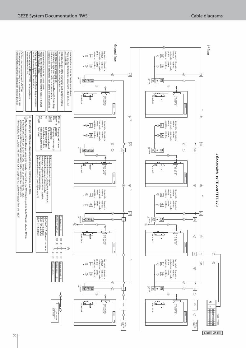
56
GEZE System Documentation RWS Cable diagrams
2 � o
ors w
ith 1
x T
E 2
20
/ TT
E 2
20
Main
s
Main
s
Key sw
itch
with
ou
t card
reader
on
the
ou
tside
Key sw
itch
with
ou
t card
reader
on
the
ou
tside
Key sw
itch
with
ou
t card
reader
on
the
ou
tside
Key sw
itch
with
ou
t card
reader
on
the
ou
tside
Key sw
itch
with
ou
t card
reader
on
the
ou
tside
Key sw
itch
with
ou
t card
reader
on
the
ou
tside
Key sw
itch
with
ou
t card
reader
on
the
ou
tside
Key sw
itch
with
ou
t card
reader
on
the
ou
tside
Key sw
itch
with
ou
t card
reader
on
the
insid
e
Key sw
itch
with
ou
t card
reader
on
the
insid
e
Key sw
itch
with
ou
t card
reader
on
the
insid
e
Key sw
itch
with
ou
t card
reader
on
the
insid
e
Key sw
itch
with
ou
t card
reader
on
the
insid
e
Key sw
itch
with
ou
t card
reader
on
the
insid
e
Key sw
itch
with
ou
t card
reader
on
the
insid
e
Key sw
itch
with
ou
t card
reader
on
the
insid
e
Panic lo
ckPan
ic lock
Panic lo
ckPan
ic lock
Panic lo
ckPan
ic lock
Panic lo
ckPan
ic lock
Fire alarm system
Burglar alarm system
Message D
oor mode
Message Locked
Message Alarm
Do
or co
ntact
Ho
ldin
g m
agn
et
Installation instructions for the door control unit:Please also heed installation instructions TZ300 no. 137351 and sk089-281.
Installation height of the emergency push button: 1200m
mRecom
mended installation height: 850 m
m
Flush-mounted door control unit:
Installatio
n in
3 stand
ard ! u
sh-m
ou
nted
bo
xes 62.5 mm
deep
Main
s sup
ply cab
le from
beh
ind
into
the u
pp
er bo
xSu
pp
ly cables fo
r perip
herals fro
m b
ehin
d in
to th
e low
er bo
x1) Po
tential-free co
ntact, o
pen
er2) Po
tential-free co
ntact, clo
ser, perm
anen
t con
tact3) Po
tential-free co
ntact, clo
ser, imp
ulse
4) Vo
ltage su
pp
ly via do
or co
ntro
l un
it po
ssible.
No
te maxim
um
po
wer co
nsu
mp
tion
5) Poten
tial-free con
tact (30V/1A
) from
the TZ
FTö331U Em
ergency exit openerFS807-10 Latch lockU
SV Em
ergency power supply
TE220 Control panel
TT220 Table-top control panel
VB Bus distributor on-site
installed near the door
VN
Mains distributor on-site
TS5000 D
oor closer
NYM
-J 3x1.5 with earth conductor
J-Y (ST) Y 2x2x0.6J-Y (ST) Y 4x2x0.6J-Y (ST) Y 2x2x0.8
Installation instructions for control panel:Please also heed installation instructions in the user m
anual Control Panel no. 10786.2 stan
dard
! ush
-mo
un
ted b
oxes 6.25 m
m d
eep are req
uired
b
ehin
d th
e con
trol p
anel fo
r installatio
n.
The co
ntro
l pan
els TE220/TTE220 can
be p
ositio
ned
an
ywh
ere in th
e bu
s line.
Cab
les rou
ted in
accord
ance w
ith V
DE 0100
Sabo
tage
-pro
of cab
le rou
ting
in acco
rdan
ce with
VD
E 0833O
nly co
nn
ect com
po
nen
ts app
roved
by th
e man
ufactu
rer
Overall len
gth
of B
US (o
ver all con
trol p
anels an
d d
oo
r con
trol u
nits) m
ax. 900m.
The # re alarm
system an
d b
urg
lar alarm system
can b
e con
nected
to o
ne TZ
320 and
relayed via th
e GEZ
E bu
s to all o
ther TZ
320s.5 # re alarm
or EM
A lin
es can b
e realised. O
nly 1 lin
e can b
e con
nected
to o
ne TZ
320.A
ll messag
es can also
be co
nn
ected sep
arately to th
e respective d
oo
r con
trol u
nits.
The m
essages ‚A
larm‘, ‚Lo
cked‘ an
d ‚D
oo
r mo
de‘ can
be o
utp
utted
as a collective m
essage fro
m o
ne TZ
320.
1st ! o
or
Gro
un
d ! o
or
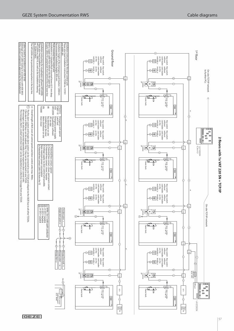
57
GEZE System Documentation RWS Cable diagrams2
� oo
rs with
1x
VA
T 2
20
SN
+ T
CP
/IP
Main
s
Main
s
Key sw
itch
with
ou
t card
reader
on
the
ou
tside
Key sw
itch
with
ou
t card
reader
on
the
ou
tside
Key sw
itch
with
ou
t card
reader
on
the
ou
tside
Key sw
itch
with
ou
t card
reader
on
the
ou
tside
Key sw
itch
with
ou
t card
reader
on
the
ou
tside
Key sw
itch
with
ou
t card
reader
on
the
ou
tside
Key sw
itch
with
ou
t card
reader
on
the
ou
tside
Key sw
itch
with
ou
t card
reader
on
the
ou
tside
Key sw
itch
with
ou
t card
reader
on
the
insid
e
Key sw
itch
with
ou
t card
reader
on
the
insid
e
Key sw
itch
with
ou
t card
reader
on
the
insid
e
Key sw
itch
with
ou
t card
reader
on
the
insid
e
Key sw
itch
with
ou
t card
reader
on
the
insid
e
Key sw
itch
with
ou
t card
reader
on
the
insid
e
Key sw
itch
with
ou
t card
reader
on
the
insid
e
Key sw
itch
with
ou
t card
reader
on
the
insid
e
Panic lo
ckPan
ic lock
Panic lo
ckPan
ic lock
Panic lo
ckPan
ic lock
Panic lo
ckPan
ic lock
Fire alarm system
Burglar alarm system
Message D
oor mode
Message Locked
Message Alarm
Do
or co
ntact
Ho
ldin
g m
agn
et
Installation instructions for the door control unit:Please also heed installation instructions TZ300 no. 137351 and sk089-281.
Installation height of the emergency push button: 1200m
mRecom
mended installation height: 850 m
m
Flush-mounted door control unit:
Installatio
n in
3 stand
ard ! u
sh-m
ou
nted
bo
xes 62.5 mm
deep
Main
s sup
ply cab
le from
beh
ind
into
the u
pp
er bo
xSu
pp
ly cables fo
r perip
herals fro
m b
ehin
d in
to th
e low
er bo
xN
YM
-J 3x1.5 with
earth co
nd
ucto
rJ-Y
(ST) Y
2x2x0.6J-Y
(ST) Y
4x2x0.6J-Y
(ST) Y
2x2x0.8
1) Poten
tial-free con
tact, op
ener
2) Poten
tial-free con
tact, closer, p
erman
ent co
ntact
3) Poten
tial-free con
tact, closer, im
pu
lse4) V
oltag
e sup
ply via d
oo
r con
trol u
nit p
ossib
le. N
ote m
aximu
m p
ow
er con
sum
ptio
n5) Po
tential-free co
ntact (30V
/1A) fro
m th
e TZ
FTö331U Em
ergency exit openerFS807-10 Latch lockU
SV Em
ergency power supply
VAT220SN
Visualisation software
(PC
on-site)VB
Bus distributor on-site
installed near the doorVN
M
ains distributor on-siteTS5000
Door closer
Overall length of BU
S (over all control panels and door control units) max. 900m
.
The # re alarm
system an
d b
urg
lar alarm system
can b
e con
nected
to o
ne TZ
320 and
relayed via th
e GEZ
E bu
s to all o
ther TZ
320s.5 # re alarm
or EM
A lin
es can b
e realised. O
nly 1 lin
e can b
e con
nected
to o
ne TZ
320.A
ll messag
es can also
be co
nn
ected sep
arately to th
e respective d
oo
r con
trol u
nits.
The m
essages ‚A
larm‘, ‚Lo
cked‘ an
d ‚D
oo
r mo
de‘ can
be o
utp
utted
as a collective m
essage fro
m o
ne TZ
320.
Installatio
n in
structio
ns fo
r visualisatio
n so
ftware VA
T220SN:
Please also
heed
installatio
n in
structio
ns fro
m u
ser man
ual
VAT220SN
no
. 098316, as well as th
e installatio
n d
rawin
g
no
. 35204-9-0955.
The VA
T220SN can
be p
ositio
ned
anyw
here in
the b
us lin
e.
Cab
les rou
ted in
accord
ance w
ith V
DE 0100
Sabo
tage
-pro
of cab
le rou
ting
in acco
rdan
ce with
VD
E 0833O
nly co
nn
ect com
po
nen
ts app
roved
by th
e man
ufactu
rer
On
-site TC
P/IP
ne
two
rk
to fu
rthe
r PC
sO
n-site
TCP
/IP n
etw
ork
US
B d
on
gle
US
B p
ort
1st ! o
or
Gro
un
d ! o
or
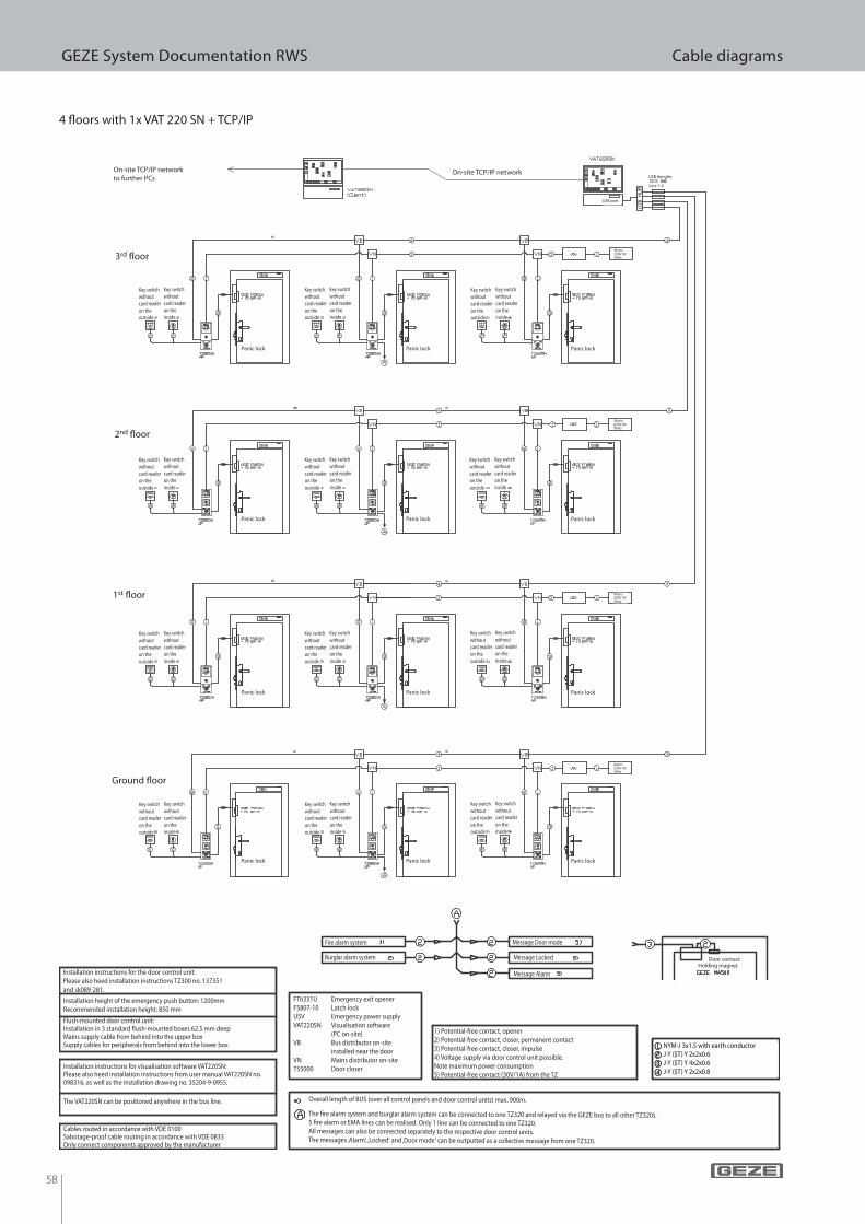
58
GEZE System Documentation RWS Cable diagrams
4 ! oors with 1x VAT 220 SN + TCP/IP
Mains250V AC50Hz
Mains250V AC50Hz
Mains250V AC50Hz
Mains250V AC50Hz
On-site TCP/IP network
to further PCsOn-site TCP/IP network
USB dongles
Line 1-4
USB port
Panic lock
Panic lock
Panic lock
Panic lock
Panic lock
Panic lock
Panic lock
Panic lock
Panic lock
Panic lock
Panic lock
Panic lock
Key switch
without
card reader
on the
outside
Key switch
without
card reader
on the
inside
Key switch
without
card reader
on the
outside
Key switch
without
card reader
on the
inside
Key switch
without
card reader
on the
outside
Key switch
without
card reader
on the
inside
Key switch
without
card reader
on the
outside
Key switch
without
card reader
on the
inside
Key switch
without
card reader
on the
outside
Key switch
without
card reader
on the
inside
Key switch
without
card reader
on the
outside
Key switch
without
card reader
on the
inside
Key switch
without
card reader
on the
outside
Key switch
without
card reader
on the
inside
Key switch
without
card reader
on the
outside
Key switch
without
card reader
on the
inside
Key switch
without
card reader
on the
outside
Key switch
without
card reader
on the
inside
Key switch
without
card reader
on the
outside
Key switch
without
card reader
on the
inside
Key switch
without
card reader
on the
outside
Key switch
without
card reader
on the
inside
Key switch
without
card reader
on the
outside
Key switch
without
card reader
on the
inside
Installation height of the emergency push button: 1200mm
Recommended installation height: 850 mm
Flush-mounted door control unit:Installation in 3 standard ! ush-mounted boxes 62.5 mm deepMains supply cable from behind into the upper boxSupply cables for peripherals from behind into the lower box NYM-J 3x1.5 with earth conductor
J-Y (ST) Y 2x2x0.6
J-Y (ST) Y 4x2x0.6
J-Y (ST) Y 2x2x0.8
FTö331U Emergency exit openerFS807-10 Latch lockUSV Emergency power supplyVAT220SN Visualisation software (PC on-site)VB Bus distributor on-site installed near the doorVN Mains distributor on-siteTS5000 Door closerInstallation instructions for visualisation software VAT220SN:
Please also heed installation instructions from user manual VAT220SN no. 098316, as well as the installation drawing no. 35204-9-0955.
The VAT220SN can be positioned anywhere in the bus line.
Cables routed in accordance with VDE 0100Sabotage-proof cable routing in accordance with VDE 0833Only connect components approved by the manufacturer
Installation instructions for the door control unit:Please also heed installation instructions TZ300 no. 137351 and sk089-281.
1) Potential-free contact, opener2) Potential-free contact, closer, permanent contact3) Potential-free contact, closer, impulse4) Voltage supply via door control unit possible. Note maximum power consumption5) Potential-free contact (30V/1A) from the TZ
Overall length of BUS (over all control panels and door control units) max. 900m.
The # re alarm system and burglar alarm system can be connected to one TZ320 and relayed via the GEZE bus to all other TZ320s.5 # re alarm or EMA lines can be realised. Only 1 line can be connected to one TZ320.All messages can also be connected separately to the respective door control units.The messages ‚Alarm‘, ‚Locked‘ and ‚Door mode‘ can be outputted as a collective message from one TZ320.
Fire alarm system
Burglar alarm system
Message Door mode
Message Locked
Message Alarm
Door contactHolding magnet
1st ! oor
Ground ! oor
2nd ! oor
3rd ! oor
59
GEZE System Documentation RWS Notes
Notes
GEZE GmbH
P.O. Box 1363
71226 Leonberg
Germany
GEZE GmbH
Reinhold-Vöster-Straße 21-29
71229 Leonberg
Germany
Telefon +49 (0) 7152-203-0
Telefax +49 (0) 7152-203-310
www.geze.com
Germany
GEZE Sonderkonstruktionen GmbH
Planken 1
97944 Boxberg-Schweigern
Tel. +49 (0) 7930-92 94-0
Fax +49 (0) 7930-92 94-10
E-Mail: [email protected]
GEZE GmbH
Niederlassung Nord/Ost
Bühringstraße 8
13086 Berlin (Weissensee)
Tel. +49 (0) 30-47 89 90-0
Fax +49 (0) 30-47 89 90-17
E-Mail: [email protected]
GEZE GmbH
Niederlassung West
Nordsternstraße 65
45329 Essen
Tel. +49 (0) 201-83 082-0
Fax +49 (0) 201-83 082-20
E-Mail: [email protected]
GEZE GmbH
Niederlassung Mitte
Adenauerallee 2
61440 Oberursel (b. Frankfurt)
Tel. +49 (0) 6171-63 610-0
Fax +49 (0) 6171-63 610-1
E-Mail: [email protected]
GEZE GmbH
Niederlassung Süd
Breitwiesenstraße 8
71229 Leonberg
Tel. +49 (0) 7152-203-594
Fax +49 (0) 7152-203-438
E-Mail: [email protected]
GEZE Service GmbH NL Südwest
Reinhold-Vöster-Straße 25
71229 Leonberg
Tel. +49 (0) 7152-92 33 34
GEZE Service GmbH NL Nord-Ost
Bühringstraße 8
13086 Berlin (Weissensee)
Tel. +49 (0) 30-47 02 17 32
GEZE Service GmbH NL West
Nordsternstraße 65
45329 Essen
Tel. +49 (0) 201-8 30 82 16
GEZE Service GmbH NL Mitte
Feldbergstraße 59
61440 Oberursel
Tel. +49 (0) 6171-63 327-0
GEZE Service GmbH NL Süd
Parkring 17
85748 Garching bei München
Tel. +49 (0) 89-120 07 42-0
Austria
GEZE Austria
Wiener Bundesstrasse 85
A-5300 Hallwang
Tel: +43/6225/87180
Fax: +43/6225/87180-299
E-Mail: [email protected]
Baltic States
GEZE GmbH Baltic States o! ce
Dzelzavas iela 120 S
1021 Riga
Tel. +371 (0) 67 89 60 35
Fax +371 (0) 67 89 60 36
E-Mail: o! [email protected]
Benelux
GEZE Benelux B.V.
Leemkuil 1
Industrieterrein Kapelbeemd
5626 EA Eindhoven
Tel. +31 (0) 40-26 290-80
Fax +31 (0) 40-26 290-85
E-Mail: [email protected]
Bulgaria
GEZE Bulgaria - Trade
Representative O! ce
61 Pirinski Prohod, entrance „B“,
4th " oor, o! ce 5,
1680 So# a
Tel. +359 (0) 24 70 43 73
Fax +359 (0) 24 70 62 62
E-Mail: o! [email protected]
India
GEZE India Private Ltd.
MF 2 & 3, Guindy Industrial Estate
Ekkattuthangal
Chennai 600 097
Tamilnadu
Tel. +91 (0) 44 30 61 69 00
Fax +91 (0) 44 30 61 69 01
E-Mail: o! [email protected]
Italy
GEZE Italia Srl
Via Giotto, 4
20040 Cambiago (MI)
Tel. +39 (0) 29 50 695-11
Fax +39 (0) 29 50 695-33
E-Mail: [email protected]
GEZE Engineering Roma Srl
Via Lucrezia Romana, 91
00178 Roma
Tel. +39 (0) 6-72 65 311
Fax +39 (0) 6-72 65 3136
E-Mail: [email protected]
Poland
GEZE Polska Sp.z o.o.
ul. Annopol 21
03-236 Warszawa
Tel. +48 (0) 22 440 4 440
Fax +48 (0) 22 440 4 400
E-Mail: [email protected]
Romania
GEZE Romania s.r.l.
IRIDE Business Park,
Str. Dimitrie Pompeiu nr. 9-9a,
Building 10, Level 2, Sector 2,
020335 Bucharest
Tel.: +40 (0) 21 25 07 750
Fax: +40 (0) 21 25 07 750
E-Mail: o! [email protected]
Russian Federation
GEZE GmbH Representative
O! ce Russia
Kolodesnij pereulok3, str. 25
O! ce Nr. 5201-5203
107076 Moskau
Tel. +7 (0) 49 55 89 90 52
Fax +7 (0) 49 55 89 90 51
E-Mail: o! [email protected]
Scandinavia – Sweden
GEZE Scandinavia AB
Mallslingan 10
Box 7060
18711 Täby, Sweden
Tel. +46 (0) 8-7323-400
Fax +46 (0) 8-7323-499
E-Mail: [email protected]
Scandinavia – Norway
GEZE Scandinavia AB avd. Norge
Industriveien 34 B
2073 Dal
Tel. +47 (0) 639-57 200
Fax +47 (0) 639-57 173
E-Mail: [email protected]
Scandinavia – Finland
Branch o! ce of GEZE Scandinavia AB
Herralantie 824
Postbox 20
15871 Hollola
Tel. +358 (0) 10-40 05 100
Fax +358 (0) 10-40 05 120
E-Mail: # [email protected]
Scandinavia – Denmark
GEZE Danmark
Branch o! ce of GEZE Scandinavia AB
Mårkærvej 13 J-K
2630 Taastrup
Tel. +45 (0) 46-32 33 24
Fax +45 (0) 46-32 33 26
E-Mail: [email protected]
South Africa
DCLSA Distributors (Pty.) Ltd.
118 Richards Drive, Halfway House,
Ext 111
P.O. Box 7934, Midrand 1685
Tel. +27 (0) 1131 58 286
Fax +27 (0) 1131 58 261
E-Mail: [email protected]
Switzerland
GEZE Schweiz AG
Bodenackerstrasse 79
4657 Dulliken
Tel. +41 (0) 62-285 54 00
Fax +41 (0) 62-285 54 01
E-Mail: [email protected]
Turkey
GEZE GmbH Türkiye - İstanbul
İrtibat Bürosu
Ataşehir Bulvarı, Ata 2/3
Plaza Kat: 9 D: 84 Ataşehir
Kadıköy / İstanbul
Tel. + 90 (0) 21 64 55 43 15
Fax + 90 (0) 21 64 55 82 15
E-Mail: o! [email protected]
Ukraine
GEZE Ukraine TOV
ul. Viskoznaya, 17,
Building 93-B, O! ce 12
02094 Kiev
Tel./Fax +38 (0) 44 501 22 25
Tel. +38 (0) 44 499 77 25
E-Mail: o! [email protected]
United Arab Emirates/GCC
GEZE Middle East
P.O. Box 17903
Jebel Ali Free Zone
Dubai
Tel. +971 (0) 4-88 33 112
Fax +971 (0) 4-88 33 240
E-Mail: [email protected]
United Kingdom
GEZE UK Ltd.
Blenheim Way
Fradley Park
Lich# eld
Sta; ordshire WS13 8SY
Tel. +44 (0) 1543 44 30 00
Fax +44 (0) 1543 44 30 01
E-Mail: [email protected]
China
GEZE Industries (Tianjin) Co., Ltd.
Shuangchenzhong Road
Beichen Economic Development
Area (BEDA)
Tianjin 300400, P.R. China
Tel. +86 (0) 22-26 97 39 95-0
Fax +86 (0) 22-26 97 27 02
E-Mail: [email protected]
GEZE Industries (Tianjin) Co., Ltd.
Branch O! ce Shanghai
Unit 25N, Cross Region Plaza
No 899, Ling Ling Road,
XuHui District
200030 Shanghai, P.R China
Tel. +86 (0) 21-523 40 960
Fax +86 (0) 21-644 72 007
E-Mail: [email protected]
GEZE Industries (Tianjin) Co., Ltd.
Branch O! ce Guangzhou
Room 17C3
Everbright Bank Building, No.689
Tian He Bei Road
510630 Guangzhou
P.R. China
Tel. +86 (0) 20-38 73 18 42
Fax +86 (0) 20-38 73 18 34
E-Mail: [email protected]
GEZE Industries (Tianjin) Co., Ltd
Branch O! ce Beijing
Room 1001, Tower D
Sanlitun SOHO
No. 8, Gongti North Road,
Chaoyang District
100027 Beijing, P.R.China
Tel. +86 (0) 10-59 35 93 00
Fax +86 (0)10-59 35 93 22
E-Mail: [email protected]
France
GEZE France S.A.R.L.
ZAC de l’Orme Rond
RN 19
77170 Servon
Tel. +33 (0) 1-60 62 60-70
Fax +33 (0) 1-60 62 60-71
E-Mail: [email protected]
Hungary
GEZE Hungary Kft.
Bartók Béla út 105-113.
Budapest
H-1115
Tel. +36 (1) 481 4670
Fax +36 (1) 481 4671
E-Mail: o! [email protected]
Iberia
GEZE Iberia S.R.L.
Pol. Ind. El Pla
C/Comerc, 2-22, Nave 12
08980 Sant Feliu de Llobregat
(Barcelona)
Tel. +34 9-02 19 40 36
Fax +34 9-02 19 40 35
E-Mail: [email protected]
GEZE SAFETY TECHNOLOGY
ID no. 132410 · Vers. EN 110715 · Subject to alterations
According to manufacturer’s liability de# ned
in the “product liability law”, the manufacturer
is obliged to provide the information (product
information and proper use, misuse, product
capacity, product maintanence, the duty to in-
form and the duty to instruct) contained in this
brochure. Non-observance of this information
relieves the manufacturer from any liability.
GEZE representative
The
measure
for our
actions