en1221s-60 senior living pendant - inovonics
TRANSCRIPT

EN1221S-60 SENIOR LIVING PENDANT
PARTNER TRAINING MATERIALS
Launch Update: September 2015
Inovonics Product Management

Confidential to Inovonics – distribution without notice is prohibited
EN1221S-60 Pendant
2
Available in dedicated neck
and wrist versions
Optional belt loop
attachment accessory for
neck version

Confidential to Inovonics – distribution without notice is prohibited
Table of Contents
3
Topic Starts on Page
Marketing Details 4
Device Operation 7
Backwards Compatibility 17
Application Software Programming Changes 19
Operational Testing 24
Back Office Operations and Other Information 28
Comparisons: EN1221S-60 to EN1223S 34

EN1221S-60
MARKETING DETAILS Positioning
Features and benefits
4

Confidential to Inovonics – distribution without notice is prohibited
Positioning
To Whom Market: Senior Living communities
Primary user: Assisted Living and
Independent Living Residents
Secondary user: Caregiver/Staff
For What Emergency Call Systems
Why Ours Designed to ensure strong resident and staff acceptance for
increased compliance
• Small, light and waterproof
• Bright lights signal alarm activation, alarm clearance
and low battery
• Vibration feature confirms alarm activation
• One year battery life
• Leverages the reliable Inovonics EchoStream® network
5

EN1221S-60 Features and Benefits Features Benefits
Size 60% smaller and lighter
than current
Easy to conceal under clothing
Comfortable for 24/7 use
Conducive to active lifestyle
Appearance Clean and modern Residents want to wear it
Activation Button High contrast color
Dimpled surface
Recessed
Improved visualization and target
Easy to locate by touch
Reduced incidence of false alarms
Alarm Activation Indicators Vibration feature confirms activation
Large, bright, continuous light
Instills confidence (‘it‘s working’)
Greater peace of mind for resident
Device Status Indicators Low battery light (5 day warning) Greater awareness of low battery condition
Instills confidence
Alarm Clearance Magnetic alarm clearance card
or button press pattern
Lights confirm successful clearance
Fast, easy and convenient
Instills confidence
Water Protection Rating Waterproof to IP67 standard Safe for use in shower and bath
Battery Life One year at 5 activations/day
and 10 minute alarm clearance time
Robust performance minimizes
battery changes
Battery Replacement Simple twist-lock access
Off-the-shelf CR2032 battery
Faster battery changes
= improved staff productivity
Attachment Methods Neck
Wrist
Belt
Soft, adjustable nylon cord with breakaway feature
Adjustable silicone watch band
Carabiner/hook to belt loop
Tailored for comfort
Attractive and easy to use
UL Certification UL 2560 Assurance of reliability
Warranty 3 years (Inovonics) Offers protection from materials and
workmanship defects under normal use

EN1221S-60
DEVICE OPERATION Device features
Basic device operation
Device indicators
Set up and registration
Power management and storage mode
Key performance information
7

Confidential to Inovonics – distribution without notice is prohibited
EN1221S-60 Features
8
Confidential to Inovonics – distribution without notice is prohibited
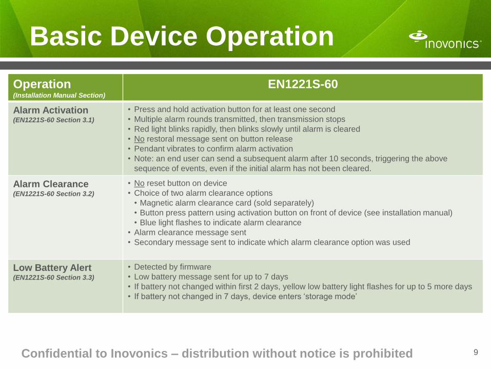
Basic Device Operation
9
Operation (Installation Manual Section)
EN1221S-60
Alarm Activation (EN1221S-60 Section 3.1)
• Press and hold activation button for at least one second
• Multiple alarm rounds transmitted, then transmission stops
• Red light blinks rapidly, then blinks slowly until alarm is cleared
• No restoral message sent on button release
• Pendant vibrates to confirm alarm activation
• Note: an end user can send a subsequent alarm after 10 seconds, triggering the above
sequence of events, even if the initial alarm has not been cleared.
Alarm Clearance (EN1221S-60 Section 3.2)
• No reset button on device
• Choice of two alarm clearance options
• Magnetic alarm clearance card (sold separately)
• Button press pattern using activation button on front of device (see installation manual)
• Blue light flashes to indicate alarm clearance
• Alarm clearance message sent
• Secondary message sent to indicate which alarm clearance option was used
Low Battery Alert (EN1221S-60 Section 3.3)
• Detected by firmware
• Low battery message sent for up to 7 days
• If battery not changed within first 2 days, yellow low battery light flashes for up to 5 more days
• If battery not changed in 7 days, device enters ‘storage mode’

Confidential to Inovonics – distribution without notice is prohibited
Device Indicators
• Vibration duration ≈ 1 second
• Alarm message sent concurrently with
vibration and initiation of red LED
• Alarm message transmitted upon
activation only (not continuously)
• Red LED blinks rapidly for 5 seconds, then
slows to every 3 seconds until alarm is
cleared
• If using magnetic alarm clearance card:
– Red LED ceases to blink
– Caregiver sees 6 quick blue LED flashes,
indicating successful alarm clearance
• If using button press pattern:
– Caregiver presses button 3 times
– Red LED ceases to blink
– Caregiver sees 2 quick blue LED flashes
– Caregiver presses button 3 more times
– Caregiver will see 6 quick blue LED
flashes, indicating successful alarm
clearance
• After clearing alarm, LED will cease to
flash or blink (in any color) until next alarm
activation is initiated
• Low battery condition message
transmitted for up to 7 days
(if battery not replaced, device enters
storage mode at end of 7 day period)
• Low battery LED programmed to begin
flashing 2 days after low battery
condition detected
• Yellow LED flashes every 5 seconds until
battery is replaced
• When battery replaced per instructions,
low battery condition will be cleared and
yellow LED will cease to flash
• Yellow LED will glow for 5 seconds (and
then stop) if activation button pressed
when device is in storage mode to
indicate missing battery condition to user
10

Confidential to Inovonics – distribution without notice is prohibited
Set Up and Registration
11
Action (Install ion Manual Section)
EN1221S-60
Record Transmitter ID
(TXID) Number
• Use human readable TXID number or
• Scan 2D barcode symbol*
• Both are permanently laser etched on rear housing
Battery Installation (EN1221S-60 Section 2.2)
• Remove twist-lock battery door
• Place CR2032 battery in battery compartment (+ side up)
• Replace battery door and turn until locked to achieve IP67 waterproof
seal
Device Registration (EN1221S-60 Section 2.3)
• When prompted by gateway or receiver to reset transmitter, press
activation button on front of device, then clear alarm per instructions
(see Section 3.2 of installation manual) to generate reset message
*Inovonics has tested readability of this 2D barcode on the pendant housing with the
Motorola DS4208-SR00007WR scanner. Barcode scanners are generally available for ≈$300.
Not designed for use with smart phone barcode reader apps

Confidential to Inovonics – distribution without notice is prohibited
Power Management
12
Battery
Classification
Description
User Accessibility
Role in Power Management
Primary CR2032
lithium-metal
coin cell battery
User replaceable • Works in concert with
secondary battery to meet
power needs
• Energy source for recharging
secondary battery
Note: design of battery holder and
contacts prevents reverse polarity
Secondary Rechargeable
lithium-ion polymer battery
Non-accessible and
non-replaceable
• Provides peak power capacity
for alarm transmissions and
vibration motor operation
To provide continuous power and achieve a one-year battery life, the EN1221S-60
employs a proprietary power management system that consists of two power
sources:

Confidential to Inovonics – distribution without notice is prohibited
Storage Mode
The new EN1221S-60 pendant has a storage mode operation that creates an ultra-low
battery state designed to preserve the life of the rechargeable secondary battery when the
device is out of service. Use cases are described below.
13
Stakeholder Storage Mode Use Cases Action Taken to Initiate Storage Mode
Inovonics • All finished goods inventory is
warehoused in storage mode
• All new pendants are shipped to
customers in storage mode
• No additional actions
VAR Partner • Unanticipated excess inventory
• Product returned from installation
sites, not needed immediately
• No additional actions, device remains in
storage mode
• Remove primary battery and press
activation button to initiate storage mode (See Installation Manual Sec 5.1)
End
Customer
• ‘Spare’ pendants
• Pendants taken out of service when
resident moves out
• Pendants with primary battery
removed
• See Installation Manual Sec 5.1
• See Installation Manual Sec 5.1
• ‘Primary battery missing’ condition is
detected by firmware at next transmission
(alarm or check-in) and storage mode will be
automatically initiated

Confidential to Inovonics – distribution without notice is prohibited
Managing the Storage Mode
14
Recommendations Notes
Minimize Inventory Levels Inovonics typically turns inventory in <4 weeks
First In, First Out (FIFO)
Inventory Management
Inovonics uses FIFO, we advise our partners to do the same
Leverage ‘Install Primary
Battery By’ Date printed on
Carton Label
Refer to this date, which is clearly
marked on the carton label.
The ‘Install Primary Battery By’
date is exactly 12 months from
the product’s date of manufacture
Install the Primary Battery
as soon as possible
If long storage periods are
expected, install primary battery
upon receipt of product to allow
secondary battery to be recharged
while pendant is not in use
If it’s not feasible to install the
primary battery upon receipt of
product, do so before the ‘Install
Primary By’ date.
• To avoid excessive discharge of the rechargeable secondary battery, the device should not be left in
storage mode for more than 12 months. Store in ambient conditions (69° F to 73°F).
• If a device remains in storage mode for >12 months, it will cease to operate if discharged to a critical level.
• At anytime within the 12 month storage period, the pendant will be fully functional immediately upon
installation of the primary battery. Refer to Section 5.2 of the EN1221S-60 Installation and Operation Manual for taking the
device out of storage mode to ensure continued operation.

Confidential to Inovonics – distribution without notice is prohibited 15
‘Install Primary Battery By’ Label
Manufacturing Date
Code (YYDDD)
Confidential to Inovonics – distribution without notice is prohibited
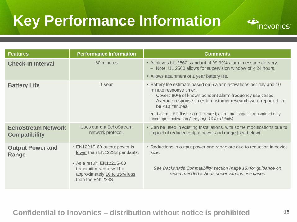
Key Performance Information
Features Performance Information Comments
Check-In Interval 60 minutes • Achieves UL 2560 standard of 99.99% alarm message delivery.
– Note: UL 2560 allows for supervision window of < 24 hours.
• Allows attainment of 1 year battery life.
Battery Life 1 year • Battery life estimate based on 5 alarm activations per day and 10
minute response time*.
– Covers 90% of known pendant alarm frequency use cases.
– Average response times in customer research were reported to
be <10 minutes.
*red alarm LED flashes until cleared; alarm message is transmitted only
once upon activation (see page 10 for details)
EchoStream Network
Compatibility
Uses current EchoStream
network protocol. • Can be used in existing installations, with some modifications due to
impact of reduced output power and range (see below).
Output Power and
Range
• EN1221S-60 output power is
lower than EN1223S pendants.
• As a result, EN1221S-60
transmitter range will be
approximately 10 to 15% less
than the EN1223S.
• Reductions in output power and range are due to reduction in device
size.
See Backwards Compatibility section (page 18) for guidance on
recommended actions under various use cases
16

EN1221S-60
BACKWARDS COMPATIBILITY
17

Confidential to Inovonics – distribution without notice is prohibited
Backwards Compatibility Guidance
18
The chart below provides guidance for addressing the expected impact of reduced pendant output power and range to ensure
adequate repeater coverage and acceptable location results under various use cases.
Use Case
Recommended Action(s)
Comments
Location
Capability (With or Without)
Site Type (New, Existing or
Either)
Pendant Mix (EN1221S-60 or
EN1223S)
Without Either Any mix • Survey site with EN7016 Survey Kit
• Use EN1223SK pendant
• Target signal margins of >10dB
• Reposition/add repeaters as needed
• Current installation literature
recommends a signal margin of >4dB
for the EN1223SK pendant.
• New target of >10dB compensates for
reduced output power on the
EN1221S-60 pendant
With
New Any mix • We strongly advise that you avoid this
option.
Testing indicates that location results for
one or both pendant types will be
inaccurate in this situation.
With New 100%
EN1221S-60
• Fingerprint with EN1221S-60
• Follow your standard guidelines to
ensure acceptable location accuracy
(e.g. # of repeaters hearing an alarm,
minimum RSSI levels)
Depending on your current practices,
you may need to adjust your quotes to
allow for more repeaters
With Existing 100%
EN1221S-60
• Test location results for new EN1221S-
60 pendants. If unacceptable:
– Re-fingerprint with EN1221S-60
• Follow your standard guidelines to
ensure acceptable location accuracy
(e.g. # of repeaters hearing an alarm,
minimum RSSI levels)
• EN1221S-60 location results are likely
to be inaccurate at sites fingerprinted
with EN1223S
• Reposition/add repeaters as needed.
• Note: After re-fingerprinting with the
EN1221S-60 pendant, you should
expect some location inaccuracy on
any remaining EN1223S pendants
while they are being phased out
during the conversion period.

EN1221S-60
APPLICATION SOFTWARE
PROGRAMMING CHANGES EchoStream message prioritization
Messaging information
Messaging information examples
19

Confidential to Inovonics – distribution without notice is prohibited
EchoStream Message Prioritization
20
The EchoStream network achieves high message delivery reliability by assigning
three levels of priority to RF messages sent by the transmitters
Priority Message Types What’s Sent
High • Alarm Multiple rounds, sent multiple times
Medium • Alarm Clearance
• Clear by Magnet
• Clear by Button Press
• Low Battery
• Primary Battery Missing
Single round, sent multiple times
Low • Supervision
• Sequence Bits
Single round, sent multiple times* (*but fewer times than high or medium priority
messages)

Confidential to Inovonics – distribution without notice is prohibited
Message Information
21

Confidential to Inovonics – distribution without notice is prohibited
Message Information Examples
22

Confidential to Inovonics – distribution without notice is prohibited
Message Information Examples
23

EN1221S-60 OPERATIONAL TESTING
Low Battery Conditions
24
Confidential to Inovonics – distribution without notice is prohibited
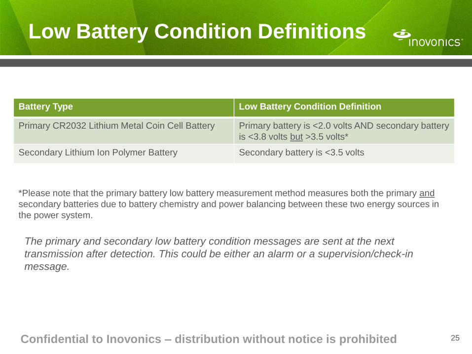
Low Battery Condition Definitions
25
*Please note that the primary battery low battery measurement method measures both the primary and
secondary batteries due to battery chemistry and power balancing between these two energy sources in
the power system.
The primary and secondary low battery condition messages are sent at the next
transmission after detection. This could be either an alarm or a supervision/check-in
message.
Battery Type Low Battery Condition Definition
Primary CR2032 Lithium Metal Coin Cell Battery Primary battery is <2.0 volts AND secondary battery
is <3.8 volts but >3.5 volts*
Secondary Lithium Ion Polymer Battery Secondary battery is <3.5 volts
Confidential to Inovonics – distribution without notice is prohibited
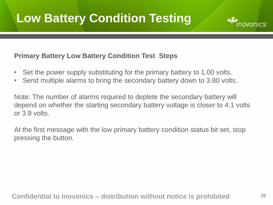
Low Battery Condition Testing
26
Primary Battery Low Battery Condition Test Steps
• Set the power supply substituting for the primary battery to 1.00 volts.
• Send multiple alarms to bring the secondary battery down to 3.80 volts.
Note: The number of alarms required to deplete the secondary battery will
depend on whether the starting secondary battery voltage is closer to 4.1 volts
or 3.9 volts.
At the first message with the low primary battery condition status bit set, stop
pressing the button.

Confidential to Inovonics – distribution without notice is prohibited
Low Battery Condition Testing
27
Secondary Battery Low Battery Test Steps
• Remove the primary battery
• Deplete the voltage for the secondary battery to less than 3.5 volts by sending
multiple alarms.
Caution: Please note that this is a ‘destructive’ test, in that the pendant will enter
into storage mode when this condition is detected, and the device will not be
recoverable.
Low battery messages on the secondary battery in actual field use are expected to be an extremely rare
occurrence. As noted on page 14 of this training document, if you install a primary coin cell battery in the
device before the end of the first 12 months after the date of manufacture, and if you replace the primary
coin cell within 7 days of a low primary battery condition being detected, the secondary battery will
remain charged and operational for the life of the device.
Please note that if you operate the device without a primary coin cell battery in the device, the secondary
battery will eventually deplete below the threshold level of 3.5 volts. For that reason, the device will send
a ‘primary battery missing message’ to alert you of that condition and allow you to remedy the situation
before the secondary battery is affected.

EN1221S-60 BACK OFFICE OPERATIONS AND OTHER INFORMATION
Ordering information
Device labeling
Cleaning and care
Attaching the Lanyard
28

Confidential to Inovonics – distribution without notice is prohibited
Ordering Information - Pendants
Pendants
Part Number Dimensions/Weight (Pendant Only) Description What’s in the Carton
EN1221S-60N 1.6”x1.6”x0.5”
0.6 oz.
Waterproof Pendant
with Neck Lanyard
• 1 pendant
• 1 lanyard (not attached)
• 1 CR2032 coin cell battery
• 1 battery door
EN1221S-60NBU Same as above
Waterproof Pendant
with Neck Lanyard (50 count bulk configuration)
• 50 pendants
• 50 individually bagged lanyards (not attached)
• 50 batteries
• 50 battery door
EN1221S-60W 1.6”x1.6”x0.5”
0.6 oz.
Waterproof Pendant
with Wristband
• 1 pendant
• 1 wristband (attached)
• 1 CR2032 coin cell battery
• 1 battery door
EN1221S-60WBU Same as above
Waterproof Pendant
with Wristband (10 count bulk configuration)
• 10 pendants (wristband attached)
• 10 batteries and 10 battery doors
29
Notes
• The EN1221S-60 Installation and Operations Manual is available at www.inovonics.com, and will not
be included in the carton
• Bulk items will not be sold individually

Confidential to Inovonics – distribution without notice is prohibited
Ordering Information - Accessories
Accessories (10 eaches per carton)
Part Number Description Used With What’s in the Carton
ACC680-BU Magnetic Alarm
Clearance Cards*
All pendants • 10 alarm clearance cards
• 1 instruction manual
ACC681-BU Replacement
Neck Lanyards
EN1221S-60N • 10 individually bagged lanyards
ACC682-BU Replacement
Wristbands
EN1221S-60W • 10 individually bagged wristbands
• 30 pack spring pins
ACC683-BU Optional Belt Loop
Attachment Kits
EN1221S-60N • 10 individually bagged carabiners with
attached j-hook
ACC684-BU Replacement
Battery Doors
All pendants • 10 battery doors
Notes
• *IATA Dangerous Goods Regulations prevent us from shipping more than 20 boxes of alarm clearance
cards in a single shipment by air
• Bulk items will not be sold individually
• Inovonics will not offer replacement CR2032 coin cell batteries

Confidential to Inovonics – distribution without notice is prohibited
Device Labeling – Laser Etch
31
Transmitter ID (TXID Number)
Battery type and
orientation
Manufacturing date code
(Julian format )
Part Number/
Product Code
Locked
padlock icon
Battery door
arrow icon
Unlocked
padlock icon
2D barcode symbol (contains TXID number)
FCC and Industry Canada
registration numbers
Open area reserved for
partner identification and/or
UL 2560 listing symbol
(adhesive label application is
recommended)
Laser etching is precise, durable,
flexible and cost-effective

Confidential to Inovonics – distribution without notice is prohibited
Cleaning and Care
32
Activity Do This Don’t Ever Do This
Cleaning • Clean with battery door in place
and in locked position
• Clean by hand using damp cloth
and mild soap or disinfectant
wipes designed for household
use
• Clean with battery door removed or in an
unlocked position
• Use strong cleaning agents such as ammonia,
bleach or quaternary disinfectant
• Use abrasive or powdered cleansers
• Use alcohol-based hand sanitizers
• Use steam autoclave or commercial sterilization
procedures using heat, chemical, gas or radiation
techniques
• Use dishwasher or washing machine
• Soak or suspend pendant in water or other liquids
Care The plastic used for this pendant is durable and designed to withstand exposure to most common substances
including soaps and skin lotions.
However, some creams, lotions or sprays may contain chemicals that may dull the housing finish.
• Avoid direct contact of the pendant with the following products: insect repellents containing DEET,
sunscreen or topical analgesics.

Confidential to Inovonics – distribution without notice is prohibited
Attaching the Lanyard
33
Attach the lanyard to the pendant such that:
1) The adjustment slide parts are centered exactly
opposite the pendant
2) The center of the breakaway ‘bead’ feature is
approximately 3.5 inches above the attachment
loop of the pendant.
Adjustment
slide parts
Breakaway
‘bead’

COMPARISONS: EN1221S-60 TO EN1223S Features and benefits
Basic device operation
Set up and registration
34

Features and Benefits Comparison of EN1221S-60 to EN1223S Series Pendants
Features EN1223S New EN1221S-60 Advantages of EN1221S-60
Size Big and heavy 60% smaller and lighter
than current
Easy to conceal under clothing
Comfortable for 24/7 use
Conducive to active lifestyle
Appearance Outdated, ‘medical’ Clean and modern Residents want to wear it
Activation Button Low contrast
Slight recess
Prone to false alarms
High contrast color
Dimpled surface
Deeper recess
Improved visualization and target
Easy to locate by touch
Reduced incidence of false alarms
Alarm Confirmation
Indicators Small, dim short duration light
(Blink and you’ll miss it)
Vibrates upon activation
Large, bright, continuous light
Instills confidence (it‘s working)
Greater peace of mind for resident
Device Status
Indicators None visible to resident Low battery light (5 day warning)
Greater awareness of low battery
Instills confidence
Alarm Clearance Hard-to-access button
Prone to wear and tear
Magnetic alarm clearance card
or button press pattern Faster, easier and more convenient
Water Protection
Rating Water-resistant (IP 54)
(if assembled correctly) Waterproof (IP 67) sealed housing Safer for use in shower and bath
Battery Life One to two years One year
(5 activations/day
and 10 minute alarm clearance time)
Robust performance minimizes
battery changes for a more
fully-featured device
Battery Replacement Time-consuming disassembly
Hard to find CR2450 battery
Simple twist-lock access
Off-the-shelf CR2032 battery
Faster battery changes
= improved staff productivity
Attachment Methods Neck
Wrist
Belt
Beaded, abrasive plastic chain
Cloth, abrasive hook and loop
Plastic clip
Soft, adjustable cord with
breakaway feature
Adjustable silicone watch band
Carabiner/hook to belt loop
More comfortable, attractive
and easy to use
Addresses skin contact issues
UL Certification UL 2560
(recent, -60 model only) UL 2560 Assurance of reliability
Warranty 3 years (Inovonics) 3 years (Inovonics)

Confidential to Inovonics – distribution without notice is prohibited
Basic Device Operation
36
Operation (Installation Manual Section)
EN1223S EN1221S-60
Alarm Activation (EN1221S-60 Section 3.1)
• Press and hold activation button for at least one
second
• Multiple alarm rounds transmitted, then stops
• Red light flashes briefly, then stops
• Restoral message sent on button release
• Same as EN1223S
• Same as EN1223S
• Red light blinks rapidly, then blinks slowly until alarm
is cleared
• No restoral message sent on button release
• Pendant vibrates to confirm alarm activation
• Note: an end user can send a subsequent alarm
after 10 seconds, triggering the above sequence of
events, even if the initial alarm has not been cleared.
Alarm Clearance (EN1221S-60 Section 3.2)
• Press reset button on back of device
• Reset message sent
• No reset button on device
• Choice of two alarm clearance options
‒ Magnetic alarm clearance card (sold separately)
‒ Button press pattern using activation button on
front of device (see installation manual)
‒ Blue light flashes to indicate alarm clearance
• Alarm clearance message sent
• Secondary message sent to indicate which
clearance option was used
Low Battery Alert (EN1221S-60 Section 3.3)
• Detected by firmware
• Low battery message sent for up to14 days
• If battery not changed at end of 14 days, device
shuts down
• Same as EN1223S
• Low battery message sent for up to 7 days
• If battery not changed within first 2 days, yellow low
battery light flashes for up to 5 more days
• If battery not changed in 7 days, device enters
‘storage mode’

Confidential to Inovonics – distribution without notice is prohibited
Basic Device Operation (continued)
37
Operation (Installation Manual Section)
EN1223S EN1221S-60
Check-In/Device
Supervision
• EN1223S checks in every 3 minutes
• EN1223S-3600 and EN1223S-60 check in every
60 minutes
• Red LED flashes briefly at each check-in interval
• EN1221S-60 checks in every 60 minutes
• No LED flashes at check-in
– Voice of customer research indicated that
flashing LED was not necessary and created
confusion among staff and residents (i.e. did I
accidentally push the button? Is something
wrong with the pendant? Why is it flashing?)
Confidential to Inovonics – distribution without notice is prohibited
Set Up and Registration
38
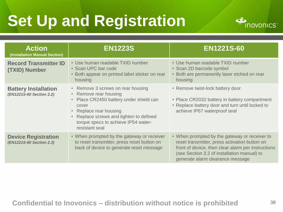
Action (Installation Manual Section)
EN1223S EN1221S-60
Record Transmitter ID
(TXID) Number
• Use human readable TXID number
• Scan UPC bar code
• Both appear on printed label sticker on rear
housing
• Use human readable TXID number
• Scan 2D barcode symbol
• Both are permanently laser etched on rear
housing
Battery Installation (EN1221S-60 Section 2.2)
• Remove 3 screws on rear housing
• Remove rear housing
• Place CR2450 battery under shield can
cover
• Replace rear housing
• Replace screws and tighten to defined
torque specs to achieve IP54 water-
resistant seal
• Remove twist-lock battery door
• Place CR2032 battery in battery compartment
• Replace battery door and turn until locked to
achieve IP67 waterproof seal
Device Registration (EN1221S-60 Section 2.3)
• When prompted by the gateway or receiver
to reset transmitter, press reset button on
back of device to generate reset message
• When prompted by the gateway or receiver to
reset transmitter, press activation button on
front of device, then clear alarm per instructions
(see Section 3.2 of installation manual) to
generate alarm clearance message