en2910a: advanced computer architecture - brown...
TRANSCRIPT

S. Reda EN2910A FALL'15
EN2910A: Advanced Computer ArchitectureTopic 03: Superscalar core architecture
Prof. Sherief Reda
School of Engineering
Brown University
1
Material from:
• Mostly from Modern Processor Design by Shen and Lipasti
• Parallel Computer Organization and Design by Debot, Annavaram and Stenstrom
• Computer Architecture: A Quantitative Approach by Hennessy and Patterson
Topics
I. Machines for ILP and superscalar pipeline
organization
II. Techniques for superscalar machines
A. Instruction flow techniques
B. Register data flow techniques
C. Memory data flow techniques
III. SW compilation techniques to expose ILP for
superscalar and VLIW machines
S. Reda EN2910A FALL'15 2

Pipeline performance
S. Reda EN2910A FALL'15 3
Different instructions may have different CPI
In pipeline designs, best case CPI = 1, when pipeline is
always filled, is rarely achieved because of stalls arising
from cache misses, structural/data/control hazards and
multi-cycle floating point operations
CPU Time = CPU Clock Cycles ´ Clock Cycle Time
=Instructions
Program´
Clock cycles
Instruction´
Seconds
Clock cycle
n
1i
ii )Count nInstructio(CPICycles Clock

Example
S. Reda EN2910A FALL'15 4
• Assume Branch can execute in 2 cycles by slowing clock 25%
• Should this be implemented?
OP Freq Cycles
ALU 43% 1
Load 21% 1
Store 12% 1
Branch 24% 3
• Old CPI = 0.43 + 0.21 + 0.12 x 2 + 0.24 x 3 = 1.48
• New CPI = 0.43 + 0.21 + 0.12 + 0.24 x 2 = 1.24
• Speedup = old time/new time
= {P x old CPI x T}/{P x new CPI x 1.25 T}
= (1.48)/(1.24 x 1.25) = 0.95
• Answer: Don’t make the change

The superscalar proposal
S. Reda EN2910A FALL'15 5
• Go beyond single instruction
pipeline, achieve IPC > 1
Dispatch multiple instructions
per cycle
• Provide more generally
applicable form of concurrency
(not just vectors) extract
instruction-level parallelism
(ILP) from sequential code that
is hard to parallelize otherwise

Superscalar performance analysis: speedup
over pipeline
S. Reda EN2910A FALL'15 6
f: vectorizable portion
s: minimum ILP
n: number of EX units
Typical Range
Speedup jumps from 3 to 4.3
for N=6, f=0.8, but s =2 instead
of s=1 (scalar)
• With high values of n, speedup drops-off rate get significantly as f
departs from 1.
• When f <= 0.75, it is better to have s=2 and n=6 rather than
having n = 100 and s = 1.

How much ILP exists?
S. Reda EN2910A FALL'15 7
Weiss and Smith [1984] 1.58
Sohi and Vajapeyam [1987] 1.81
Tjaden and Flynn [1970] 1.86 (Flynn’s bottleneck)
Tjaden and Flynn [1973] 1.96
Uht [1986] 2.00
Smith et al. [1989] 2.00
Jouppi and Wall [1988] 2.40
Johnson [1991] 2.50
Acosta et al. [1986] 2.79
Wedig [1982] 3.00
Butler et al. [1991] 5.8
Melvin and Patt [1991] 6
Wall [1991] 7 (Jouppi disagreed)
Kuck et al. [1972] 8
Riseman and Foster [1972] 51 (no control dependences)
Nicolau and Fisher [1984] 90 (Fisher’s optimism)
• Function of the benchmark
• Function of the compiler
• Branches and data dependencies impose practical ILP limit

From scalar to superscalar
1. Scalar upper bound on throughput
– IPC <= 1 or CPI >= 1
– Solution: wide (superscalar) pipeline
2. Rigid unified pipeline
– Long latency for each instruction
– Solution: diversified, specialized
pipelines
3. Rigid pipeline stall policy
– One stalled instruction stalls all newer
instructions
– Solution: Out-of-order execution,
distributed execution pipelines
S. Reda EN2910A FALL'15 8

1. Parallel pipelines
S. Reda EN2910A FALL'15 9
A parallel pipeline with width s can
concurrently process up to s instructions
in each cycle.
• Logic of each stage increases by s.
Decoding (& dispatching) increases
by more than s.
• Interstage communication logic
increases by s2.
• Register and memory ports increase
by s.

Example of static superscalar: Intel’s Pentium
S. Reda EN2910A FALL'15 10
Introduced 1993
Technology 0.8 micron
Transistors: 3.1 million
Speed: 66 Mhz
CISC ISA
# stages: 5
Issue width: 2-way static
• Two single-stage asymmetric integer ALUs
• One three-stage floating point
• Decode unit examines pairs of instructions and
statically issues them simultaneously if there are no
hazards and can be supported by both ALUs;
otherwise, only first one is issued.
• Results of two instructions are put back in order
when completed and written back to register file or
memory

2. Diversified pipelines
S. Reda EN2910A FALL'15 11
Problem of unified pipelines: Each instruction
type only required a subset of the stages, but
must traverse all stages idling in
unnecessary stages.
Advantages of diversified pipes:
• Customization efficiency
• Minimum necessary latency
Design Issue:
• Need a dispatch unit/stage; checks for
hazards.
• Number and mix of functional units?

Example: Motorola 88110
S. Reda EN2910A FALL'15 12
Introduced 1992
Technology 1 micron
Transistors: 1.3 million
Speed: 50 Mhz
RISC ISA
# stages: 4
Issue width: 2
• 10 functional units. Except for
divide, all units are single-cycle
latency or pipelined
• If no hazards dispatches two
instructions per cycle.
• If hazards dispatches first
instruction; second instruction
moves to 1st dispatch slot and a
new instruction takes 2nd dispatch
slot.
• Dispatches in order; writing back
could be out-of-order.
3
stages
2
stages

3. Dynamic pipelines
S. Reda EN2910A FALL'15 13
• Out-of-order (dynamic) execution
• Replace single-entry pipeline buffer by
complex multi-entry pipeline buffers
enable instructions to enter and leave the
buffers in different orders.
• What to do with Interrupts and exceptions
(e.g., arithmetic exceptions, page faults)?
• Re-order buffer puts back instructions in
program order for WB enables precise
exceptions.
• Precise exception handling: synchronized
with an instruction; all preceding
instructions must complete; subsequent
instructions flushed; instruction must
resume execution after handling.

Superscalar organization
S. Reda EN2910A FALL'15 14
template conceptual 6-stage
superscalar pipeline

1. Issues in fetching
S. Reda EN2910A FALL'15 15
Objective: Fetch multiple instructions, s, per
cycle
@ every cycle: use PC to index I-cache. If
group of s instructions are in same cache
block done in one cycle.
Issues:
1. Misalignment: If group straddles blocks
need two cycles reduces fetch
bandwidth; might induce a miss for
second block. Solutions for
misalignment: static SW compiler
techniques and HW alignment.
2. Control-changing instructions: What
happens if a branch is in the middle of
the fetch group?
Instruction Memory
PC
3 instructions fetched

Example: IBM RS/6000 HW fetch alignment
S. Reda EN2910A FALL'15 16
• Two-way set associative instruction cache organized into 4 subarrays.
• Each block is 64 bytes (16 instructions) and spans 4 physical rows.
• If misalignment is detected, T-logic units autoincrement address and
rotation network reorders presents instructions in original order.
• Example: if PC indexes into subarray 2, T-logic of subbarrays 0 & 1
auto increments
• Goal: issue four
instructions per cycle

2. Issues in decoding
• Primary Tasks:
– Identify individual instructions
– Determine instruction types
– Determine dependences between instructions
– Identify control-flow changing instructions to quickly give
feedback to fetch unit.
– For CISC: translate instructions to one or more μops.
• Important factors:
– ISA (RISC vs CISC)
– Pipeline width impacts dependency detection hardware and
register file complexity.
S. Reda EN2910A FALL'15 17

Example: Pentium Pro fetch/decode unit
S. Reda EN2910A FALL'15 18
P6 microarchitecture, 1995
Technology: 0.5 micron
Transistors: 5.5 million
Speed: 150 Mhz
#stages: 11
Issue width: 5-way dynamic
• @ each cycle: 16 aligned bytes are delivered to the instruction buffer.
• Instructions within the buffer are identified and aligned in IF stage.
• Three parallel decoders decode simultaneously. 1st decoder can
handle and translate any instruction (up to 4 uops), 2nd and 3rd decode
only simple instructions (1 uop).
• Two pipeline stages for decoding.

3. Instruction dispatching
S. Reda EN2910A FALL'15 19
• All functional units can operate independently in a distributed fashion.
• Dispatching unit must resolve all inter-instruction dependencies and
dispatch operations to the appropriate functional units.
• Need to read register operands to dispatch with the operation. What if
the operands are not yet ready?

3. Dispatching & issuing
S. Reda EN2910A FALL'15 20
Centralized Distributed
• Reservation station: holds instructions that need to wait for operands
or unit availability takes up slack between decoding and execution
stages.
• Centralized reservation station: feeds all functional units
• Distributed stations: instructions are dispatched to reservation
stations, and then issued to functional unit when appropriate.

4. Instruction execution
• Current trends:
– More parallelism
– Deeper pipelines
– More diversity
• Functional unit types
– Integer
– Floating point
– Load/store Branch
– Specialized units (e.g., MAC, multimedia)
– What is the best mix and numbers?
• Additional complexities:
– Bypass network for forwarding is a
interconnect from/to FU inputs and outputs;
grows quadratically as a function of number
of FUs.
S. Reda EN2910A FALL'15 21

5/6. Issues in completion/retirement
S. Reda EN2910A FALL'15 22
• Completion updating processor
state.
• Retiring updating memory.
• Sometimes completion and retiring
are used interchangeably.
• Should we retire out-of-order?
• Precise exceptions
• Solutions:
• Reorder buffer enter out-of-
order, but exit in order.
• Store buffer
Topics
I. Machines for ILP and superscalar pipeline
organization
II. Techniques for superscalar machines
A. Instruction flow techniques
B. Register data flow techniques
C. Memory data flow techniques
III. SW compilation techniques to expose ILP for
superscalar and VLIW machines
S. Reda EN2910A FALL'15 23

Superscalar techniques
S. Reda EN2910A FALL'15 24
I-cache
FETCH
DECODE
COMMIT
D-cache
BranchPredictor Instruction
Buffer
StoreQueue
ReorderBuffer
Integer Floating-point Media Memory
Instruction
RegisterData
MemoryData
Flow
EXECUTE
(ROB)
Flow
Flow
1. Instruction flow:
– Fetch alignment
– Branches, jumps, calls: predict
target, direction
2. Register data flow:
– Register renaming:
RAW/WAR/WAW
3. Memory data flow:
– In-order stores: WAR/WAW
– Store queue: RAW
– Data cache misses

Performance degradation due to branches
S. Reda EN2910A FALL'15 25
• Control-flow changing instructions include jumps (subroutine calls,
returns, and goto) and conditional branches (if-else and loops).
Form 20% of the code, with a branch instruction encountered every
6 instructions on the average.
• Number of stall cycles can be dictated from address generation
and/or conditional resolution.
• In superscalar, number of empty instruction slots is equal to the
number of stalled cycles multiplied by superscalar pipeline width!
• Pipeline stalls sequential bottleneck of Amdahl’s law

Stalled cycles due to target address generation
S. Reda EN2910A FALL'15 26
Decode Buffer
Fetch
Dispatch Buffer
Decode
Reservation
Dispatch
Store Buffer
Complete
Retire
StationsIssue
Execute
FinishCompletion Buffer
Branch
PC-rel.
Reg.ind.
Reg.ind.withoffset
• Decode: PC = PC + DISP (adder) (1 cycle penalty)
• Dispatch: PC = (R2) ( 2 cycle penalty)
• Execute: PC = (R2) + offset (3 cycle penalty)

Stalled cycles due to condition resolution
S. Reda EN2910A FALL'15 27
Decode Buffer
Fetch
Dispatch Buffer
Decode
Reservation
Dispatch
Store Buffer
Complete
Retire
StationsIssue
Execute
FinishCompletion Buffer
Branch
CCreg.
GPreg.valuecomp.
• Dispatch: 2 cycle penalty
• Execute: 3 cycle penalty

Branch prediction
S. Reda EN2910A FALL'15 28
Target address generation Target Speculation
– Access register:
PC, General purpose register, Link register
– Perform calculation:
+/- offset, autoincrement, autodecrement
Condition resolution Condition speculation
– Access register:
Condition code register, General purpose register
– Perform calculation:
Comparison of data register(s)
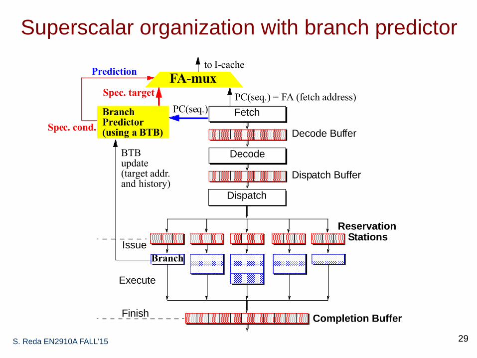
Superscalar organization with branch predictor
S. Reda EN2910A FALL'15 29
Decode Buffer
Fetch
Dispatch Buffer
Decode
Reservation
Dispatch
StationsIssue
Execute
FinishCompletion Buffer
Branch
to I-cache
PC(seq.) = FA (fetch address)
PC(seq.)BranchPredictor(using a BTB)
Spec. target
BTBupdate
Prediction
(target addr.and history)
Spec. cond.
FA-mux

Target speculation
S. Reda EN2910A FALL'15 30
• Branch Target Buffer: small cache in fetch stage
– Previously executed branches, address, taken history, target(s)
• Fetch stage compares current FA against BTB
– If match, use prediction
– If predict taken, use BTB target
• When branch executes, BTB is updated
• Optimization:
– Size of BTB: increases hit rate
– Prediction algorithm: increase accuracy of prediction

Condition speculation
S. Reda EN2910A FALL'15 31
1. Biased Not Taken– Hardware prediction
– Does not affect ISA
– Not effective for loops
2. Software Prediction– Extra bit in each branch instruction
– Bit set by compiler or user; can use profiling
– Static prediction, same behavior every time
3. Prediction based on branch offset– Positive offset: predict not taken
– Negative offset: predict taken
4. Prediction based on dynamic historyA. Dynamic BP using Smith algorithm
B. Two-level adaptive (correlating) BP (Yeh and Patt)
C. Tournament predictors

A. Dynamic branch prediction
S. Reda EN2910A FALL'15 32
Branch prediction algorithm is based on FSM. Current state used to
generate prediction.
Branch target address and state updated when branch completes
executed and actual outcome is known.
Branch information could be located in a separate table )pattern
history table) also indexed by PC.
00/N 01/N 10/T 11/T
T T T
NTNTNT
TNT
Information
to predict
Examples of BP FSMs
0/N
1/T
T
T N
N

B. Two-level adaptive (correlating) BP
S. Reda EN2910A FALL'15 33
• In a 2-level predictor we add history bits to access the btb
• History can be global (all branches) or private (this branch only)
• Notation: the first (capital) letter refers to the type of history; the last
letter refers to whether each predictor is private in the table.
• g or g means “global”; p or p means “private”

B. GAg two-level BP
S. Reda EN2910A FALL'15 34
00...00
00...01
00...10
11...10
11...11
1 1 1 1 0
Branch History Register(shift left when update)
Pattern History Table (PHT)
PHTBits
Prediction
Branch Result
index
FSMLogic
old
new
Motivation:if (a==2) then a:=0;if (b==2) then b:=0;if (a!=b) then ---
Outcomes of most recent branch outcomes is stores in branch
history register (BHR); the BHR is a shift register where the
outcome of each branch is shifted into the end.
Branches with the same global history interfere with each
other and predicted by the same bits

B. GAp two-level BP
S. Reda EN2910A FALL'15 35
To FSM
• Histories are shared by all branches but predictors are specific
to each branch

B. PAg two-level BP
S. Reda EN2910A FALL'15 36
• Per-address history table and global predictor table
• Histories are tracked for each branch but predictors are shared
• All branches with the same per-address history share the same
predictor and interfere with each other’s prediction

• Per-address history table and per-address predictor table
B. PAp two-level BP
S. Reda EN2910A FALL'15 37

Superscalar techniques
S. Reda EN2910A FALL'15 38
I-cache
FETCH
DECODE
COMMIT
D-cache
BranchPredictor Instruction
Buffer
StoreQueue
ReorderBuffer
Integer Floating-point Media Memory
Instruction
RegisterData
MemoryData
Flow
EXECUTE
(ROB)
Flow
Flow
1. Instruction flow:
– Fetch alignment
– Branches, jumps, calls: predict
target, direction
2. Register data flow:
– Register renaming:
RAW/WAR/WAW
3. Memory data flow:
– In-order stores: WAR/WAW
– Store queue: RAW
– Data cache misses
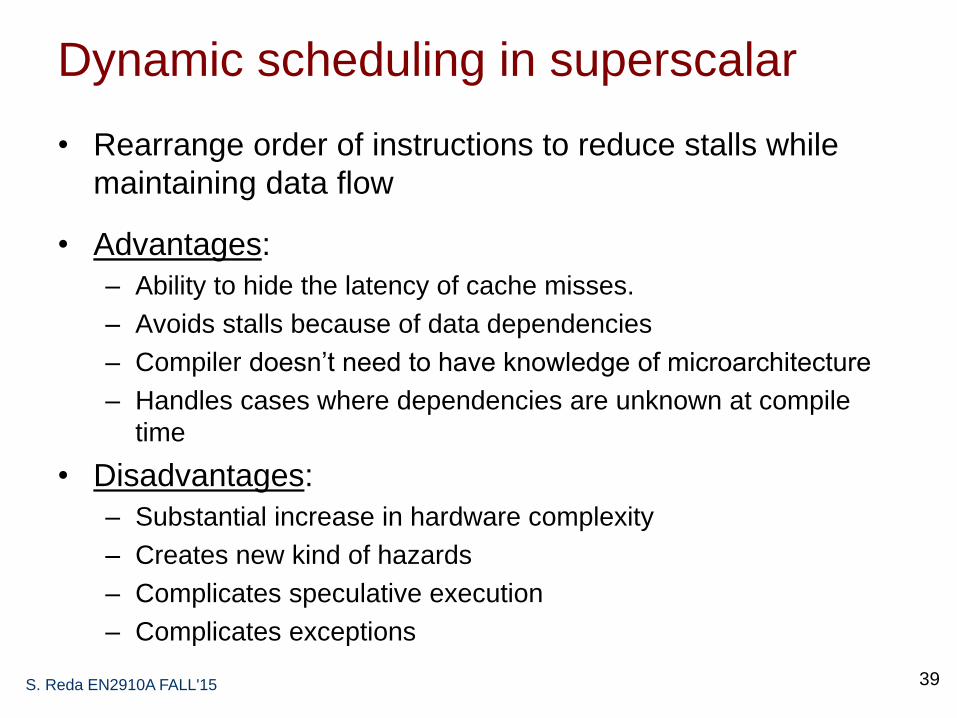
Dynamic scheduling in superscalar
• Rearrange order of instructions to reduce stalls while
maintaining data flow
• Advantages:
– Ability to hide the latency of cache misses.
– Avoids stalls because of data dependencies
– Compiler doesn’t need to have knowledge of microarchitecture
– Handles cases where dependencies are unknown at compile
time
• Disadvantages:
– Substantial increase in hardware complexity
– Creates new kind of hazards
– Complicates speculative execution
– Complicates exceptions
S. Reda EN2910A FALL'15 39

Register hazards from dynamic scheduling
S. Reda EN2910A FALL'15
40
Read After Write
(RAW) hazard
(true dependency)
Write After Read
(WAR) hazard
(anti dependency)
Write After Write
(WAW) hazard
(output dependency)
add $s2, $s1, $s0
sub $s4, $s2, $s3
add $s4, $s2, $s0
…..
sub $s2, $s1, $s3
add $s2, $s1, $s0
….
sub $s2, $t2, $t3
• Introduced by OOO
• Just a name
dependency – no
values being
transmitted
• Dependency can be
removed by
renaming registers
(either by compiler or
HW)
• Introduced by OOO
• Just a name
dependency – no
values being
transmitted
• Dependency can be
removed by
renaming registers
(either by compiler or
HW)
• A true data
dependency
because values
are transmitted
between the
instructions

Example
S. Reda EN2910A FALL'15 41
w: R4 R0+R8x: R2 R0*R4y: R4 R4+R8z: R8 R4*R2

Dynamic scheduling using classic
Tomasulo’s algorithm
• First implemented in IBM 360/91.
• Tracks when operands are available and forwarded them
to where they are needed handles RAW hazards.
• Introduces register renaming eliminates WAW and
WAR hazards.
• Out of order execution and out of order committing
can’t handle speculative execution or precise exceptions
without extensions to hardware organization.
S. Reda EN2910A FALL'15 42

Organization of dynamic execution engine
S. Reda EN2910A FALL'15 43
FP mult

Tomasulo’s algorithm
S. Reda EN2910A FALL'15 44
– Dispatch:
• Get next instruction from FIFO queue (dispatch buffer)
• If a RS is available, dispatch the instruction to the RS with
operand values if available; else send pending RS tag.
• If a RS is not available, then stall (structural hazard).
– Issue/Execute
• If instruction in RS is waiting for operand monitor the CDB
and latch results when tag is identified.
• When all operands are available, issue the instruction;
execution can take a number of cycles.
• No instruction allowed to initiate execution until all branches that
proceed it in program order have been completed.
– Write result
• Write result on CDB and from there to reservation stations and
RF.

Example
S. Reda EN2910A FALL'15 45
w: R4 R0+R8x: R2 R0*R4y: R4 R4+R8z: R8 R4*R2
Adder takes two cycles to compute result
Mult/Div takes three cycles to compute result

Example
S. Reda EN2910A FALL'15 46
w: R4 R0+R8x: R2 R0*R4y: R4 R4+R8z: R8 R4*R2
• How were RAW, WAR, and WAW hazards handled in the example?

Hardware-based speculation
S. Reda EN2910A FALL'15 47
• Execute instructions along predicted execution
paths but only commit the results if prediction was
correct
• Instruction commit: allowing an instruction to
update the register file when instruction is no longer
speculative
• Need to decouple forwarding of results through
CDB and actual updating of register and memory
need an additional piece of hardware to prevent
any irrevocable action (i.e. updating state or taking
an execution) until an instruction commits

Modern dynamic execution engines
S. Reda EN2910A FALL'15 48
• Reorder buffer
(ROB) enables
speculative
execution and
precise
exceptions.
• Supports
multiple issues
and writing using
wide CDB.
• Store buffer is
now not needed

Re-order/completion buffer
S. Reda EN2910A FALL'15 49
A ROB is a FIFO buffer holds the results of instruction between
completion and commit. An entry is created for every instruction as it
is dispatched from the instruction queue (i.e., dispatch buffer).
Each entry has four fields: (i) instruction type (e.g.,
branch/store/register); (ii) destination field (e.g., register number or
memory address); (iv) value field and (iv) ready field.
Register values and memory values are not written until an
instruction retires (i.e., when it is the oldest instruction in ROB).
On misprediction: speculated entries in ROB are cleared.
On exceptions: not recognized until it is ready to retire.
If a register does not have its value available a pointer should be
included to the ROB entry # that will hold the latest value. Pointers
form the register alias table (RAT).

Steps of dynamic execution with speculation
• Dispatch: get an instruction from the instruction queue
and dispatch to a reservation station if it has an empty
slot and en empty slot exists in ROB. Send values from
RF, ROB or instead send ROB entry number tag.
• Issue: send to execution unit if all operands are
available else monitor CDB.
• Execute and write to CDB: broadcast results on CDB
with ROB entry tag; update waiting entries in reservation
stations and ROB.
• Retire: when instruction reaches head of ROB; update
RF if instruction is speculated correctly; else flush.
Reclaim ROB entry.
S. Reda EN2910A FALL'15 50

Superscalar techniques
S. Reda EN2910A FALL'15 51
I-cache
FETCH
DECODE
COMMIT
D-cache
BranchPredictor Instruction
Buffer
StoreQueue
ReorderBuffer
Integer Floating-point Media Memory
Instruction
RegisterData
MemoryData
Flow
EXECUTE
(ROB)
Flow
Flow
1. Instruction flow:
– Branches, jumps, calls: predict
target, direction
– Fetch alignment
– Instruction cache misses
2. Register data flow:
– Register renaming:
RAW/WAR/WAW
3. Memory data flow:
– In-order stores: WAR/WAW
– Store queue: RAW
– Data cache misses

Load processing
S. Reda EN2910A FALL'15 52
• Example: LD R1, 100[R2]
1. Dispatch: Dispatch from instruction queue (dispatch buffer) to
LD/ST reservation station and create entry in ROB. Forward
values from RF, ROB or instead forward ROB entry number tag.
2. Execution: (1) issue to EX unit to compute target address
computation and translate from virtual to physical when source;
(2) issue to cache to read value.
3. Completion: write the read data to CDB along with the ROB
entry tag.
4. Retiring: when the load’s ROB entry has both its address and
value ready, and it is the oldest instruction in the ROB, then it is
retired by writing the load value from ROB to the destination
register.

Store processing
• Example: ST R1, 50[R2]
1. Dispatch: Dispatch from instruction queue (dispatch buffer) to
LD/ST reservation station and create entry in ROB. Forward
values from RF, ROB or instead forward ROB entry number tag.
2. Execution: issue to EX unit to compute target address
computation and translate from virtual to physical when source;
3. Completion: write the generated to CDB along with the ROB
entry tag.
4. Retiring: when the store’s ROB entry has both its address and
value ready, and it is the oldest instruction in the ROB, then it is
retired by writing the store value into the memory.
S. Reda EN2910A FALL'15 53

Memory data dependences
S. Reda EN2910A FALL'15 54
• Loads and stores can execute out of order with respect to other
types of instructions. because we can always check for
dependencies by comparing register IDs.
• How about loads and stores with respect to each other?
– Register dependencies are easy to solve:
• LD R1, 50[R2]
• LD R3, 100[R1]
– Can we resolve memory dependencies?
• “Memory Aliasing” = Two memory references involving the
same memory location (collision of two memory addresses).
• “Memory Disambiguation” = Determining whether two
memory references will alias or not.

Avoiding hazards with memory dependencies
S. Reda EN2910A FALL'15 55
ST R1, 50[R2]
.
.
ST R3, 50[R4]
Retiring values to
memory always occur
in order no WAW
because of memory
aliasing.
LD R1, 50[R2]
.
.
ST R3, 50[R4]
Retiring values to
memory always occur
in order no WAR
because of memory
aliasing.
LD R1, 50[R2]
.
.
LD R3, 50[R4]
No issues with memory
aliasing.
ST R1, 50[R2]
.
.
LD R3, 50[R4]
Potential for RAW hazards because of memory aliasing.

Handling RAW memory hazards
S. Reda EN2910A FALL'15 56
ST R1, 50[R2]
.
.
LD R3, 50[R4]
Potential for RAW hazards because of memory aliasing.
• Possible pessimistic solution:
Execute load and stores in
order superscalar processor
can take a big performance hit
• Optimistic: execute OOO but
mark speculative and do not
retire the LD until address is
resolved.

Superscalar techniques
S. Reda EN2910A FALL'15 57
I-cache
FETCH
DECODE
COMMIT
D-cache
BranchPredictor Instruction
Buffer
StoreQueue
ReorderBuffer
Integer Floating-point Media Memory
Instruction
RegisterData
MemoryData
Flow
EXECUTE
(ROB)
Flow
Flow
1. Instruction flow:
– Fetch alignment
– Branches, jumps, calls: predict
target, direction
2. Register data flow:
– Register renaming:
RAW/WAR/WAW
3. Memory data flow:
– In-order stores: WAR/WAW
– Store queue: RAW
– Data cache misses

Compilation techniques to expose ILP
Goals of SW compilation techniques for superscalar:
Maximize the ILP extracted from SW by re-arranging
instructions during compilation to avoid stalls during runtime
and maximize throughput.
Techniques:
• Pipeline scheduling (no insertion – already discussed)
• Code scheduling (instruction re-arrangement- already discussed)
1. Loop unrolling
2. Software pipelining
• VLIW architectures: taking superscalar complexity to SW.
S. Reda EN2910A FALL'15 58

1. Loop unrolling
S. Reda EN2910A FALL'15 59
• Goals: (1) reduce loop overhead, and (2) enable better scheduling by allowing instructions from different iterations to be scheduled together.
Loop: L.D F0,0(R1)
ADD.D F4,F0,F2
S.D F4,0(R1) ;drop DADDUI & BNE
L.D F6,-8(R1)
ADD.D F8,F6,F2
S.D F8,-8(R1) ;drop DADDUI & BNE
L.D F10,-16(R1)
ADD.D F12,F10,F2
S.D F12,-16(R1) ;drop DADDUI & BNE
L.D F14,-24(R1)
ADD.D F16,F14,F2
S.D F16,-24(R1)
DADDUI R1,R1,#-32
BNE R1,R2,Loop
note: number of live registers vs. original loop

1. Loop unrolling + scheduling
S. Reda EN2910A FALL'15 60
• schedule the unrolled loop to avoid stalls:
Loop: L.D F0,0(R1)
L.D F6,-8(R1)
L.D F10,-16(R1)
L.D F14,-24(R1)
ADD.D F4,F0,F2
ADD.D F8,F6,F2
ADD.D F12,F10,F2
ADD.D F16,F14,F2
S.D F4,0(R1)
S.D F8,-8(R1)
DADDUI R1,R1,#-32
S.D F12,16(R1)
S.D F16,8(R1)
BNE R1,R2,Loop

1. Loop unrolling limitations
• Improvement from loop overhead tapers off.
• Works well if loop iterations are independent but problem
with loop-carried RAW dependency limits amount of
unrolling
• Example:
for (i=2;i<100;i++) a[i]:= a[i-2] + b[i];
• Consumes architectural registers due to renaming
register pressure.
• Code expansion impact I-cache and memory
• What if we do not know the loop limit?
S. Reda EN2910A FALL'15 61

2. Software pipelining
S. Reda EN2910A FALL'15 62
• A software-pipelined loop interleaves instructions from different loop
iterations (without no need for unrolling), thus separating the
dependent instructions within one iteration of the original loop
less chance of stalling.
• The start-up and finish-up code will correspond to the portions
above and below the software-pipelined iteration.

2. Software pipelining example
S. Reda EN2910A FALL'15 63
iteration i
iteration i+1
iteration i+2
• What are the startup and cleanup codes?

2. Software pipeline vs. loop unrolling
• The major advantage of software pipelining over straight
loop unrolling is that software pipelining consumes less
code space.
• Loop unrolling reduces the overhead of the loop—the
branch and counter update code improvement
eventually tapers off after a few unrolled iterations.
• Software pipelining reduces the time when the loop is
not running at peak speed to once per loop at the
beginning and end.
• Because these techniques attack two different types of
overhead, the best performance can come from doing
both.
S. Reda EN2910A FALL'15 64

VLIW architectures: exporting superscalar
HW complexity to SW
S. Reda EN2910A FALL'15 65
[from Fisher et al.]

VLIW Pros and Cons
Compiler schedules and groups instructions to be issued together in
Very Large Instruction Words (VLIW) to maximize ILP.
Compiler detects and avoids hazards:
reorder instructions into issue packets
no dependencies within a packet
pad with NOPs if necessary
Simplifies superscalar hardware.
Works well in data-intensive applications with little control.
• Disadvantages:
– Some hazards can’t be resolved during compile time compiler
must be conservative loss in performance compared to
dynamic superscalar
– Poor portability and backward compatibility
S. Reda EN2910A FALL'15 66

Summary of superscalar architectures
S. Reda EN2910A FALL'15 67
• Pros: Improved single-thread throughput: hide memory latency;
avoid or reduces stalls; and ability to fetch and execute multiple
instructions per cycle.
• Cons:
impacts silicon area
impacts power consumption
impacts design complexity impact clock cycle deep
pipelining more design complexity for speculation HW.
• SW compilation techniques enable
more ILP from the same HW
simplify HW (e.g., VLIW) at the expense of code portability
• Final verdict: great single-thread performance but at the expense
of energy efficiency.