enabling 10 mol/kg swing capacity via heat integrated sub ... library/events/2016/c02 cap...
TRANSCRIPT

Enabling 10 mol/kg swing capacity via heat integrated sub-ambient pressure swing adsorption
Eli Carter, Stephen DeWitt, Jongwoo Park, Hector RubieraResearchers
Ryan P. LivelyPrincipal Investigator
Yoshiaki Kawajiri, Matthew J. Realff, David S. Sholl, Krista S. WaltonCo-Principal Investigators
Georgia Institute of TechnologySchool of Chemical & Biomolecular Engineering
Atlanta, GA 30332
Bruce LaniProgram Manager, DOE-NETL
DOE-NETL CO2 Capture Technology Project review MeetingThursday, August 11th , 2016

Key Idea:Combine:
(i) Sub-ambient gas processing and energy recovery with
(ii) ultra-porous metal-organicframeworks and
(iii) space- and energy-efficient fiber sorbent contactors
to yield a game-changing process strategy
2
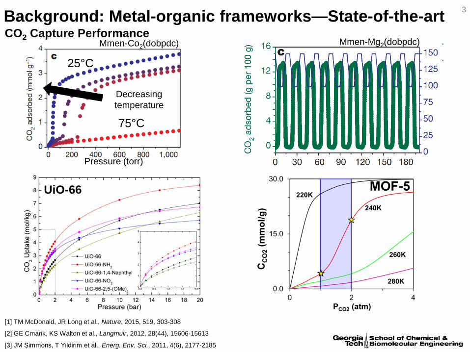
Background: Metal-organic frameworks—State-of-the-artMmen-Co2(dobpdc)
Decreasing temperature
[1] TM McDonald, JR Long et al., Nature, 2015, 519, 303-308
UiO-66
Mmen-Mg2(dobpdc)CO2 Capture Performance
[3] JM Simmons, T Yildirim et al., Energ. Env. Sci., 2011, 4(6), 2177-2185
[2] GE Cmarik, KS Walton et al., Langmuir, 2012, 28(44), 15606-15613
Pressure (torr)
25°C
3
75°C

Background: Hollow fiber sorbents, a mass producible structured sorbent inspired by hollow fiber membrane spinning
Ideal temperature swing adsorption1000 µm
[1] RP Lively, WJ Koros et al., Ind. Eng. Chem. Res., 2009, 48(15), 7314-73244
Bundle of 40 fibers in a 1.5’ module at GT

Background: Fiber sorbents for PSA applications
2 µm
H2/CO2 separations
5
[1] RP Lively, WJ Koros et al., Int. J. Hydrogen Energ., 2012, 37(20), 15227-15240

Project scope—details on key ideas
• Rapid pressure swing adsorption is more straightforward than rapid temperature swing adsorption (has been commercialized)
• Sub-ambient conditions increase adsorption selectivity and working capacity
• Immense pore volume and surface area of MOFs are advantageous at sub-ambient conditions and moderate CO2 partial pressures (~1-2 bar)
• Weaknesses of MOFs addressed through contactor (hollow fiber sorbents) and through process strategy
6
RCPSA
Sub-ambient membrane system
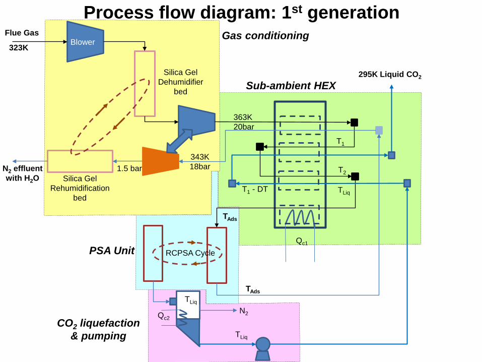
BlowerFlue Gas
323K
363K 20bar
343K 18bar
295K Liquid CO2Silica Gel
Dehumidifier bed
Silica Gel Rehumidification
bed
T1
TAds
T2
TAdsTLiq
TLiqT1 - DT
1.5 barN2 effluent with H2O
TLiq
RCPSA CycleQc1
Qc2
Process flow diagram: 1st generation
N2
Gas conditioning
Sub-ambient HEX
PSA Unit
CO2 liquefaction & pumping

Process Scope—Key Research Topics
Five major activity areas are proposed in this work:
(1) UiO-66 / MOF synthesis, sub-ambient adsorption characterization, and stability,
(2) Composite hollow fiber spinning (cellulose acetate/polysulfonefibers containing UiO-66 / MOF sorbents),
(3) RCPSA system construction and testing of fiber sorbent modules and hollow fiber sorbent modules with bore-side phase change material,
(4) Modeling and optimization of fiber and hollow fiber module operation as well as flue gas conditioning optimization, and
(5) Overall system techno-economic analysis.
8

Process Scope—Key Topics, BP1
Five major activity areas are proposed in this work for BP1:
Task 2.0: Generate >250 g/quarter of UiO-66, sub-ambient sorption isotherms, and simple fiber sorbents
Task 3.0: Spin fiber sorbents
Task 4.0: Stability of module seals at sub-ambient conditions
Task 5.0: Develop model for hollow fiber sorbent module
Task 6.0: RCPSA Testing and construction
9

Task 2—sorption isotherms, experimental 10
0
2
4
6
8
10
12
0 1 2 3 4 5 6
Upt
ake
(mm
ol/g
)
Pressure (bar)
UiO-66 High Pressure Isotherms
283-1
273-1
263-1
253-1
243-1
233-1
223-1
213-1
210 220 230 240 250 260 270 2800
1
2
3
4
5
6
7Pads = 2.0 barPdes = 0.1 bar
UiO-66 UiO-66-NH2
UiO-66-(NH2)2
UiO-66-CH2NH2
∆NC
O2 (
mol
/kg)
Temperature (K)
Swing capacities
UiO-66 can achieve impressive swing capacities at sub-ambient conditions—but higher pore volumes needed for 10+ mol/kg
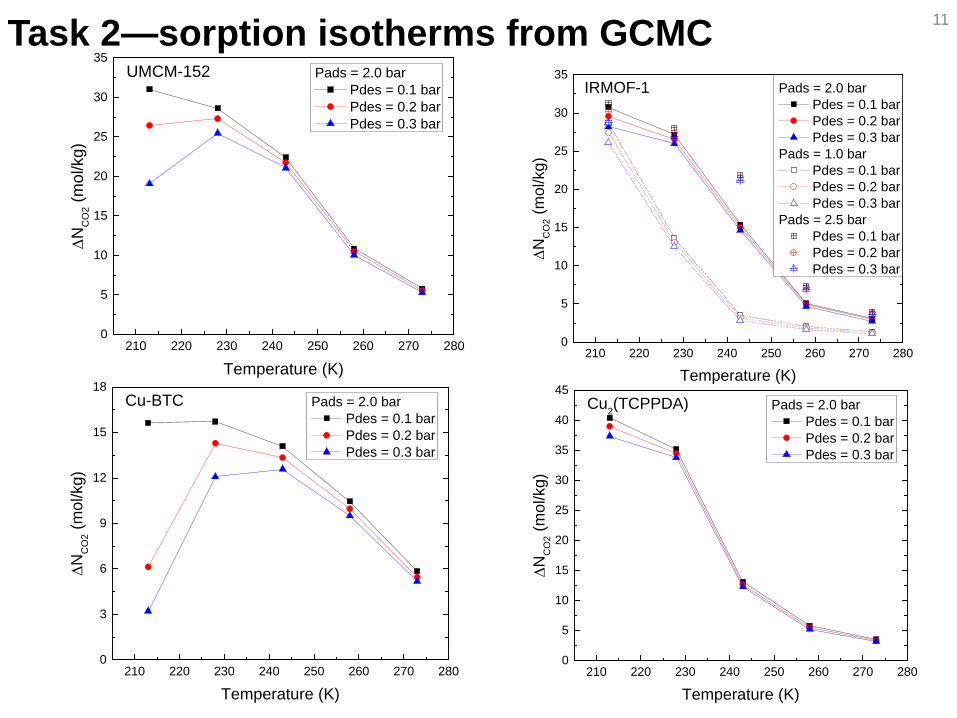
Task 2—sorption isotherms from GCMC 11
210 220 230 240 250 260 270 2800
5
10
15
20
25
30
35IRMOF-1
∆NC
O2 (
mol
/kg)
Temperature (K)
Pads = 2.0 bar Pdes = 0.1 bar Pdes = 0.2 bar Pdes = 0.3 bar
Pads = 1.0 bar Pdes = 0.1 bar Pdes = 0.2 bar Pdes = 0.3 bar
Pads = 2.5 bar Pdes = 0.1 bar Pdes = 0.2 bar Pdes = 0.3 bar
210 220 230 240 250 260 270 2800
5
10
15
20
25
30
35
40
45Cu2(TCPPDA)
∆NC
O2 (
mol
/kg)
Temperature (K)
Pads = 2.0 bar Pdes = 0.1 bar Pdes = 0.2 bar Pdes = 0.3 bar
210 220 230 240 250 260 270 2800
5
10
15
20
25
30
35UMCM-152
∆NC
O2 (
mol
/kg)
Temperature (K)
Pads = 2.0 bar Pdes = 0.1 bar Pdes = 0.2 bar Pdes = 0.3 bar
210 220 230 240 250 260 270 2800
3
6
9
12
15
18Cu-BTC
∆NC
O2 (
mol
/kg)
Temperature (K)
Pads = 2.0 bar Pdes = 0.1 bar Pdes = 0.2 bar Pdes = 0.3 bar
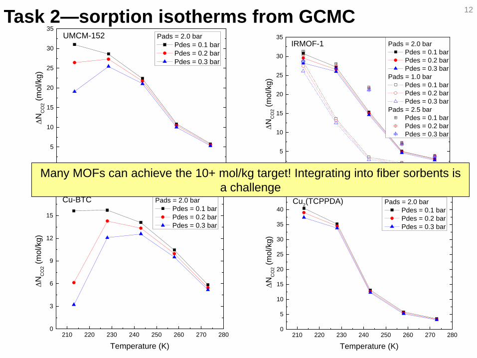
Task 2—sorption isotherms from GCMC 12
210 220 230 240 250 260 270 2800
5
10
15
20
25
30
35IRMOF-1
∆NC
O2 (
mol
/kg)
Temperature (K)
Pads = 2.0 bar Pdes = 0.1 bar Pdes = 0.2 bar Pdes = 0.3 bar
Pads = 1.0 bar Pdes = 0.1 bar Pdes = 0.2 bar Pdes = 0.3 bar
Pads = 2.5 bar Pdes = 0.1 bar Pdes = 0.2 bar Pdes = 0.3 bar
210 220 230 240 250 260 270 2800
5
10
15
20
25
30
35
40
45Cu2(TCPPDA)
∆NC
O2 (
mol
/kg)
Temperature (K)
Pads = 2.0 bar Pdes = 0.1 bar Pdes = 0.2 bar Pdes = 0.3 bar
210 220 230 240 250 260 270 2800
5
10
15
20
25
30
35UMCM-152
∆NC
O2 (
mol
/kg)
Temperature (K)
Pads = 2.0 bar Pdes = 0.1 bar Pdes = 0.2 bar Pdes = 0.3 bar
210 220 230 240 250 260 270 2800
3
6
9
12
15
18Cu-BTC
∆NC
O2 (
mol
/kg)
Temperature (K)
Pads = 2.0 bar Pdes = 0.1 bar Pdes = 0.2 bar Pdes = 0.3 bar
Many MOFs can achieve the 10+ mol/kg target! Integrating into fiber sorbents is a challenge

Task 2, 3: UiO-66 scale-up and hollow fiber sorbents 13
325 g of UiO-66 from Inmondo Tech UiO-66/Cellulose Acetate fiber sorbents: ~55 wt%
Water stable MOFs retain crystallinity and porosity after fiber sorbent spinning

Task 2,3: What about water-sensitive MOFs? 14
Cu-BTC/Matrimid fiber sorbents: ~55 wt%

Task 2,3: What about water-sensitive MOFs? 15
Cu-BTC/Matrimid fiber sorbents: ~55 wt%

Task 2,3: What about water-sensitive MOFs? 16
Cu-BTC/Matrimid fiber sorbents: ~55 wt%
MOFs with water stability issues can now be integrated into fiber sorbents!Operational stability is less of an issue as flue gas is dehydrated + substantial industry
experience with water sensitive sorbents (e.g., LiX)

Task 4, 6—Rapid pressure swing adsorption 17
Shell side feed (low ΔP feed)
Sub-ambient breakthrough experiments on UiO-66 and UiO-66 fiber sorbents currently underway

Task 4: Dynamic model development 18
18
Combined heat, mass, and momentum balance on the fiber, including transient heat conduction w/ heat source
density values help to track the melting front
Dynamic model guides experiments and RCPSA cycle development

Task 4: Dynamic model development 19
19
Combined heat, mass, and momentum balance on the fiber, including transient heat conduction w/ heat source
density values help to track the melting front
Dynamic model guides experiments and RCPSA cycle development

Process Scope—Key Topics, BP1
Five major activity areas are proposed in this work for BP1:
Task 2.0: Generate >250 g/quarter of UiO-66, sub-ambient sorption isotherms, and simple fiber sorbents—Complete
Task 3.0: Spin fiber sorbents—Complete
Task 4.0: Stability of module seals at sub-ambient conditions—Ongoing, 60% (sub-ambient exposure completed, leak rate of module seals ongoing)
Task 5.0: Develop model for hollow fiber sorbent module—Complete
Task 6.0: RCPSA Testing and construction—Ongoing, 80% complete (remaining items: breakthrough curves for UiO-66 powders and fibers).
20

Summary 21
• Novel polymer/MOF sorbent composite hollow fibers will be used in new sub-ambient RPSA process for post-combustion CO2 capture
• 50% experimental demonstration• 50% prediction, modeling, optimization, and economic feasibility analysis
• Viability of concept is being demonstrated• Potential for game-changing swing capacities by utilizing MOFs in sub-ambient
conditions
• Georgia Tech and Inmondo Tech are partners on this project
• Annual reports, annual review meetings and conferences presentations and quarterly reports will be used to update DOE on team activities
• DOE contribution: ~$2.0M Georgia Tech contribution: ~$0.5M

BudgetDOE Contribution1st year: $705,4412nd year: $681,8453rd year: $599,698Total: $1,986,984 (79%)
Cost Share Provided by Georgia Tech: $513,792 (21%)
Total Budget: $2,500,776
5 primary researchers supported (2 post-doctoral researchers, 3 graduate student researchers)
5 PIs supported (Lively, Kawajiri, Realff, Sholl, Walton)
Major equipment purchases/construction: Sub-ambient rapid pressure swing adsorption units
22

Personnel
Principal Investigators:
Georgia TechRyan Lively, Project Director, Inmondo liaison, hollow fibers and RCPSA system
Yoshiaki Kawajiri, Process optimization, cyclic adsorption processes
Matthew Realff, Process systems engineering, technoeconomic analysis
David Sholl, Adsorption and diffusion in nanoporous materials
Krista Walton, Adsorption in MOFs and MOF synthesis
Inmondo TechDr. Karen Tuleg, Inmondo PI, Sorption and gas storage
23

RisksDescription of Risk Probability (Low,
Moderate, High)Impact
(Low, Moderate, High)Risk Management
Mitigation and Response StrategiesTechnical Risks:MOFs do not exhibit ~10 mol/kg swing capacity between 1 and 2 bar CO2 partial pressure
Moderate Moderate (a) Technoeconomic analysis and modeling effort will determine impact of > 10 mol/kg swing vs. 5-10 mol/kg swing.
(b) Other scalable MOFs can be considered if >10 mol/kg is critical
MOF particles do not survive spinning process
Low High If required, MOFs can be grown within porous polymer supports post-spinning. Preliminary data from Lively indicates that MOFs retain their porosity and crystallinity post-spinning.
Failure of sealing for fiber modules
Low Moderate If required, specialty epoxies resistant to temperature changes will be used to seal modules.
Instability of MOF to flue gas contaminants
Low High Functionalized MOFs will be tested, providing various materials for use. Additional flue gas processing can be used if necessary.
Resource Risks:Delays in production of MOFs by Inmondo Tech
Low High MOFs will be produce in excess of minimum requirement in year 1 to ensure availability. Capability to deliver materials in this manner has already been demonstrated.
Management Risks:Difficulty in recruiting postdocs/grad students at GT
Low Moderate Shift personnel between tasks to manage temporary vacancies
Lack of coordination among project partners
Low Moderate Project partners already have a proven record of collaboration; regular project meetings are scheduled with all partners
24

BP 1 Task List & Milestones 25
Budget Period
Task/Subtask No. Milestone Description Planned Completion Actual Completion
Verification Method
1 1 Updated Project Management Plan
08/31/2015 Project Management Plan file
1 1 Kickoff Meeting 10/01/2015 Presentation file1 2.1 Produce 250+ g of UiO-66
@ >900 m2/g surface area and >2.5 mol CO2/kg @ 273K & 1 bar
01/31/16 Report to DOE
1 2.2 Generate sub-ambient isotherms
04/30/16 Report to DOE
1 2.3 Syringe fibers using UiO-66
04/30/16 Report to DOE
1 3 Spin monolithic fibers 09/30/16 Report to DOE1 4 RCPSA module
construction & seal testing09/30/16 Report to DOE
1 5 Bare fiber module model development
04/30/16 Report to DOE

BP2 Task List & Milestones 26
2 6 Test PSA using syringe fiber samples
04/31/17 Report to DOE
2 7 Produce 250+ g of UiO-66 @ >900 m2/g surface area and >2.5 mol CO2/kg @ 273K & 1 bar
01/31/17 Report to DOE
2 8 MOF moisture and acid gas test (SO2 and steam exposure)
09/30/17 Report to DOE
2 9 Lumen layer synthesis and barrier properties
04/31/17 Report to DOE
2 10 Demonstrate hollow fiber lumen layer synthesis
09/30/17 Report to DOE
2 11 PCM integration into modules
09/30/17 Report to DOE
2 12 Model development of fibers with PCM
09/30/17 Report to DOE
2 13 Modeling phase change and adsorption using experimental data
09/30/17 Report to DOE
2 14 Process flowsheet optimization
09/30/17 Report to DOE

BP3 Task List & Milestones 27
3 15 Process flowsheet refinement
06/30/18 Report to DOE
3 16 Produce 250+ g of UiO-66 @ >900 m2/g surface area and >2.5 mol CO2/kg @ 273K & 1 bar
01/31/18 Report to DOE
3 17 Construct/test RCPSA for dirty gas testing
04/30/18 Report to DOE
3 18 Model validation for hollow fiber module—model validation for composite fibers
04/30/18 Report to DOE
3 19 Monolithic fiber sorbent stability in dirty gas RCPSA
06/30/18 Report to DOE
3 20 Test hollow fibers containing phase change material in PSA
09/30/2018 Report to DOE
3 21 Complete Technoeconomic assessment
09/30/2018 Report to DOE
3 22 Test a demonstration module
09/30/2018 Report to DOE

Initial high level process analysis using 10 mol/kg swing 28
• Plant parasitic load: 16.7%
• Installed capital costs: $188.2 x 10⁶
• Total annual cost (operating expenses + amortized capital): $72.8 x10⁶/yr
• CO2 captured per year: 4.50 x 10⁶ tons CO2/yr
• CO2 capture cost: $19.0/ton, $21/tonne
• Number of 8” module elements needed: 36,000
• Estimated footprint (assuming modules stacked 10 high): ~200 m2 fora 500 MWe coal-fired power plant