enabling dual chassis fault tolerance with intel ... ss7.pdf · splitting the functionality of a...
TRANSCRIPT

Intel inCommunications
Enabling Dual Chassis Fault Tolerance with Intel® NetStructure™
SS7 Boards
Application Note
ContentsAbstract . . . . . . . . . . . . . . . . . . . . . . . . . . . . . . . . . . . . . . . . . . . . . . . . . . . . . . . 1
Introduction . . . . . . . . . . . . . . . . . . . . . . . . . . . . . . . . . . . . . . . . . . . . . . . . . . . . 1
Implementing an SS7 Signaling Point on More Than One Chassis . . . . . . . . . . . . . . . . 2
Concepts . . . . . . . . . . . . . . . . . . . . . . . . . . . . . . . . . . . . . . . . . . . . . . . . . . . . . . 3
Dual MTP3 Concepts . . . . . . . . . . . . . . . . . . . . . . . . . . . . . . . . . . . . . . . . . . . . . . . . . . . . 3
State Machines above the MTP . . . . . . . . . . . . . . . . . . . . . . . . . . . . . . . . . . . . . . . . . . . . 3
Dual Telephony Operation (Based on CIC) . . . . . . . . . . . . . . . . . . . . . . . . . . . . . . . . . . . 4
Dual SCCP Considerations (Maintenance of Sub-System States) . . . . . . . . . . . . . . . . . 5
Dual TCAP Operation . . . . . . . . . . . . . . . . . . . . . . . . . . . . . . . . . . . . . . . . . . . . . . . . . . . . 6
TCAP Users (GSM-MAP, IS41-MAP, INAP) . . . . . . . . . . . . . . . . . . . . . . . . . . . . . . . . . . . 7
Configuration . . . . . . . . . . . . . . . . . . . . . . . . . . . . . . . . . . . . . . . . . . . . . . . . . . 8
Configuration at MTP3 . . . . . . . . . . . . . . . . . . . . . . . . . . . . . . . . . . . . . . . . . . . . . . . . . . . 8
Configuration of ISUP and TUP . . . . . . . . . . . . . . . . . . . . . . . . . . . . . . . . . . . . . . . . . . . 10
Configuration of SCCP . . . . . . . . . . . . . . . . . . . . . . . . . . . . . . . . . . . . . . . . . . . . . . . . . . 14
Configuration of TCAP . . . . . . . . . . . . . . . . . . . . . . . . . . . . . . . . . . . . . . . . . . . . . . . . . . 14
Inter-Chassis Communication . . . . . . . . . . . . . . . . . . . . . . . . . . . . . . . . . . . 14
Considerations for a Resilient Application . . . . . . . . . . . . . . . . . . . . . . . . . 17
Setting System.txt Values . . . . . . . . . . . . . . . . . . . . . . . . . . . . . . . . . . . . . . . 18
System.txt for Protocols Running on the Host . . . . . . . . . . . . . . . . . . . . . . . . . . . . . . . 18
System.txt for Protocols Running on a Signaling Processor Card . . . . . . . . . . . . . . . 19
Enabling Dual Chassis Fault Tolerance with Intel® NetStructure™ SS7 Boards Application Note
AbstractIn order to achieve “five nines” availability and a high degree of fault tolerance in an SS7environment using Intel® NetStructure™ SS7 components, an SS7 end point spread over twochassis can be built. Splitting the functionality of a signaling point by implementing an SS7 nodeover more than one chassis isolates the hardware processors on the chassis from each other. Thisseparation lets one processor continue if the other fails, allowing the total system to remain in service.
Intel NetStructure SS7 components are designed for this dual processor approach and provide thearchitecture for splitting a point code over two active SS7 protocol engines. With this technique,the links in an SS7 link set can be spread between two separate chassis when Intel NetStructureSS7 signaling cards are installed in each. This application note discusses the design andimplementation of such a dual-chassis method for achieving high availability and fault tolerance.
IntroductionBecause of the high expectation of service reliability by the users of public telephony networks,equipment manufacturers and system integrators demand high levels of fault tolerance andavailability, often citing the ‘five nines’ for availability (requiring a system to be operational for99.999% of the time).
Such systems need to be able to continue to offer service even when partial hardware or softwarefailure has occurred. There are several, well-known methods of achieving this type of reaction topartial failure in the signaling component of communications networks, including:
■ Multiple signaling paths (SS7 links and link sets) to each end point
■ The distribution of these paths through independent interfaces and cabling
■ Distribution of the processing of SS7 terminations at a single signaling point between multipleprocessing cards in a single chassis
■ Physical isolation and duplication of the SS7 interface for a single signaling point (the Intel®
NetStructure™ SIU and SS7 boards approach)
■ Splitting the functionality of a signaling point, including the application layer, between two chassis(the subject of this paper)
The first three on this list can be achieved in SS7 by implementing multiple links (64 or 56 Kbpschannels) between two adjacent inter-communicating points. (By definition, these links will all be inthe same link set). The final two options can be achieved by the use of two independent but co-operating SS7 protocol stacks, normally in separate but interconnected chassis to provide ahigher degree of resilience to failures.
Enabling Dual Chassis Fault Tolerance with Intel® NetStructure™ SS7 Boards Application Note
1
Link set
SS7 SS7
Side A Side B
Application
TCAP
SCCP
MTP
ISUP/TUP
TCAP
SCCP
MTP
ISUP/TUP
Application
Inter-chassiscommunication
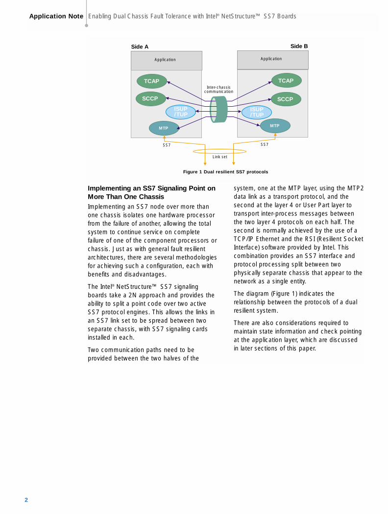
Figure 1 Dual resilient SS7 protocols
Implementing an SS7 Signaling Point onMore Than One ChassisImplementing an SS7 node over more thanone chassis isolates one hardware processorfrom the failure of another, allowing the totalsystem to continue service on completefailure of one of the component processors orchassis. Just as with general fault resilientarchitectures, there are several methodologiesfor achieving such a configuration, each withbenefits and disadvantages.
The Intel® NetStructure™ SS7 signalingboards take a 2N approach and provides theability to split a point code over two activeSS7 protocol engines. This allows the links inan SS7 link set to be spread between twoseparate chassis, with SS7 signaling cardsinstalled in each.
Two communication paths need to beprovided between the two halves of the
system, one at the MTP layer, using the MTP2data link as a transport protocol, and thesecond at the layer 4 or User Part layer totransport inter-process messages betweenthe two layer 4 protocols on each half. Thesecond is normally achieved by the use of aTCP/IP Ethernet and the RSI (Resilient SocketInterface) software provided by Intel. Thiscombination provides an SS7 interface andprotocol processing split between twophysically separate chassis that appear to thenetwork as a single entity.
The diagram (Figure 1) indicates therelationship between the protocols of a dualresilient system.
There are also considerations required tomaintain state information and check pointingat the application layer, which are discussedin later sections of this paper.
Application Note Enabling Dual Chassis Fault Tolerance with Intel® NetStructure™ SS7 Boards
2
MTP A
MTP B
Link set 1Inter-chassislink set
Link set 0 SS7
SS7SS7
SSP/SCP
SSP/SCP
MTP A
MTP B
Link set 1
Inter-chassislink set
Link set 0
STP
Traffic from MTP BTraffic from MTP A
Link set 2STP
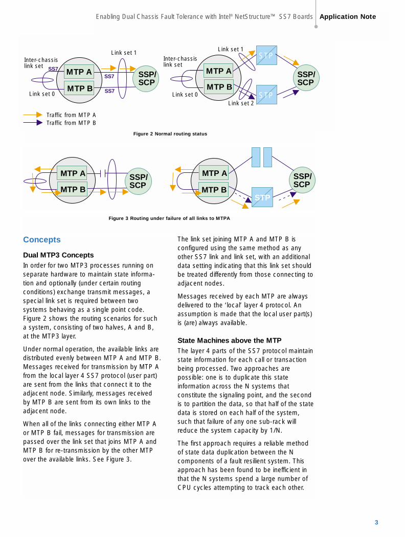
Figure 2 Normal routing status
MTP A
MTP B
SSP/SCP
MTP A
MTP B
SSP/SCP
STP
Figure 3 Routing under failure of all links to MTPA
Concepts
Dual MTP3 ConceptsIn order for two MTP3 processes running onseparate hardware to maintain state informa-tion and optionally (under certain routingconditions) exchange transmit messages, aspecial link set is required between twosystems behaving as a single point code. Figure 2 shows the routing scenarios for sucha system, consisting of two halves, A and B,at the MTP3 layer.
Under normal operation, the available links aredistributed evenly between MTP A and MTP B.Messages received for transmission by MTP Afrom the local layer 4 SS7 protocol (user part)are sent from the links that connect it to theadjacent node. Similarly, messages receivedby MTP B are sent from its own links to theadjacent node.
When all of the links connecting either MTP Aor MTP B fail, messages for transmission arepassed over the link set that joins MTP A andMTP B for re-transmission by the other MTPover the available links. See Figure 3.
The link set joining MTP A and MTP B isconfigured using the same method as anyother SS7 link and link set, with an additionaldata setting indicating that this link set shouldbe treated differently from those connecting toadjacent nodes.
Messages received by each MTP are alwaysdelivered to the ‘local’ layer 4 protocol. Anassumption is made that the local user part(s)is (are) always available.
State Machines above the MTPThe layer 4 parts of the SS7 protocol maintainstate information for each call or transactionbeing processed. Two approaches arepossible: one is to duplicate this stateinformation across the N systems thatconstitute the signaling point, and the secondis to partition the data, so that half of the statedata is stored on each half of the system,such that failure of any one sub-rack willreduce the system capacity by 1/N.
The first approach requires a reliable methodof state data duplication between the Ncomponents of a fault resilient system. Thisapproach has been found to be inefficient inthat the N systems spend a large number ofCPU cycles attempting to track each other.
Enabling Dual Chassis Fault Tolerance with Intel® NetStructure™ SS7 Boards Application Note
3
SSP
ISUP/TUP
MTP SS7
SS
7
SS7
Chassis A
Chassis B
MTP
ISUP/TUP
Inter-chassisCommunication(RSI)
Voicetrunks
Voicetrunks
Received message for circuit terminating on Chassis A
Transmit message for circuit terminating on Chassis A
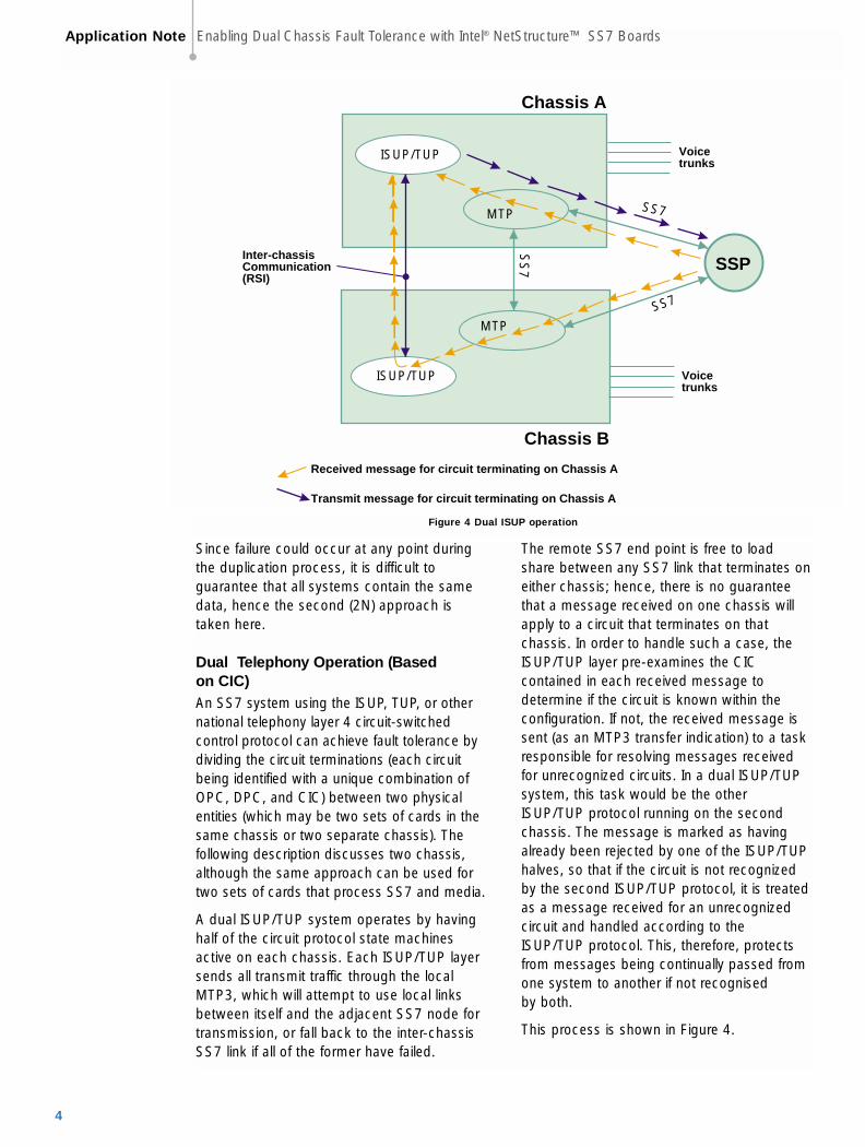
Figure 4 Dual ISUP operation
Since failure could occur at any point duringthe duplication process, it is difficult toguarantee that all systems contain the samedata, hence the second (2N) approach istaken here.
Dual Telephony Operation (Based on CIC)An SS7 system using the ISUP, TUP, or othernational telephony layer 4 circuit-switchedcontrol protocol can achieve fault tolerance bydividing the circuit terminations (each circuitbeing identified with a unique combination ofOPC, DPC, and CIC) between two physicalentities (which may be two sets of cards in thesame chassis or two separate chassis). Thefollowing description discusses two chassis,although the same approach can be used fortwo sets of cards that process SS7 and media.
A dual ISUP/TUP system operates by havinghalf of the circuit protocol state machinesactive on each chassis. Each ISUP/TUP layersends all transmit traffic through the localMTP3, which will attempt to use local linksbetween itself and the adjacent SS7 node fortransmission, or fall back to the inter-chassisSS7 link if all of the former have failed.
The remote SS7 end point is free to loadshare between any SS7 link that terminates oneither chassis; hence, there is no guaranteethat a message received on one chassis willapply to a circuit that terminates on thatchassis. In order to handle such a case, theISUP/TUP layer pre-examines the CICcontained in each received message todetermine if the circuit is known within theconfiguration. If not, the received message issent (as an MTP3 transfer indication) to a taskresponsible for resolving messages receivedfor unrecognized circuits. In a dual ISUP/TUPsystem, this task would be the otherISUP/TUP protocol running on the secondchassis. The message is marked as havingalready been rejected by one of the ISUP/TUPhalves, so that if the circuit is not recognizedby the second ISUP/TUP protocol, it is treatedas a message received for an unrecognizedcircuit and handled according to theISUP/TUP protocol. This, therefore, protectsfrom messages being continually passed fromone system to another if not recognised by both.
This process is shown in Figure 4.
Application Note Enabling Dual Chassis Fault Tolerance with Intel® NetStructure™ SS7 Boards
4

Applicationnode 1
Trunks containingvoice and signalling
Applicationnode 2
SIU✝
Ethernet
SIU✝
SS7
Trunks containingvoice only
Link Set
Figure 5 SIU Approach
The message itself is transported from onesystem to another through an applicationdependent mechanism, although the RSI andTCP/IP method is possibly the simplest.
The SIU solves the problem of fault resilienceby separating the SS7 interface from theprocessing of the media using an Ethernet,with two SIUs behaving as a single point codefor fault tolerance, as shown in Figure 5. Byseparating the SS7 interface, the SIU alsoallows systems to be built using up to 32application nodes that process the voicecircuits (media).
Dual SCCP Considerations (Maintenanceof Sub-System States)SCCP enhances the routing capabilities of theMessage Transfer Part (MTP) by supportingthe concept of addressable sub-systems. Therouting availability (the allowed or prohibitedstate) of all known local and remote sub-systems is maintained within the SCCP layer.
In a system consisting of N SCCP layers (ormultiple instances of SCCP) behaving as thesame point code, both the user applicationand the remote end points need to be able toexchange SCCP data messages through anyof the SCCP instances and expect the routingavailability tables in each SCCP to be thesame. In order to achieve this, the SCCP layerhas been enhanced with a broadcastmechanism that transmits any change of localor remote routing status to a broadcast task.The broadcast task is responsible forcommunicating the changes to the N-1 (other)SCCP instances. In a dual system, thebroadcast task is simply the other SCCP layerwith both layers communicating using themessage-based API. In a dual chassis/sub-rack environment, these messages can beconveyed by the RSI and TCP/IP Ethernetcombination.
Enabling Dual Chassis Fault Tolerance with Intel® NetStructure™ SS7 Boards Application Note
5
SCP
SCCP
MTP SS7
SS
7
SS7
Chassis A
Chassis B
MTP
SCCP
Inter-chassiscommunication(RSI)
Received SCCP management state change event on Chassis A
Local SCCP state change event sent through chassis B
+
+
Copy taken andsent to SCCP B
Copy taken andsent to SCCP A
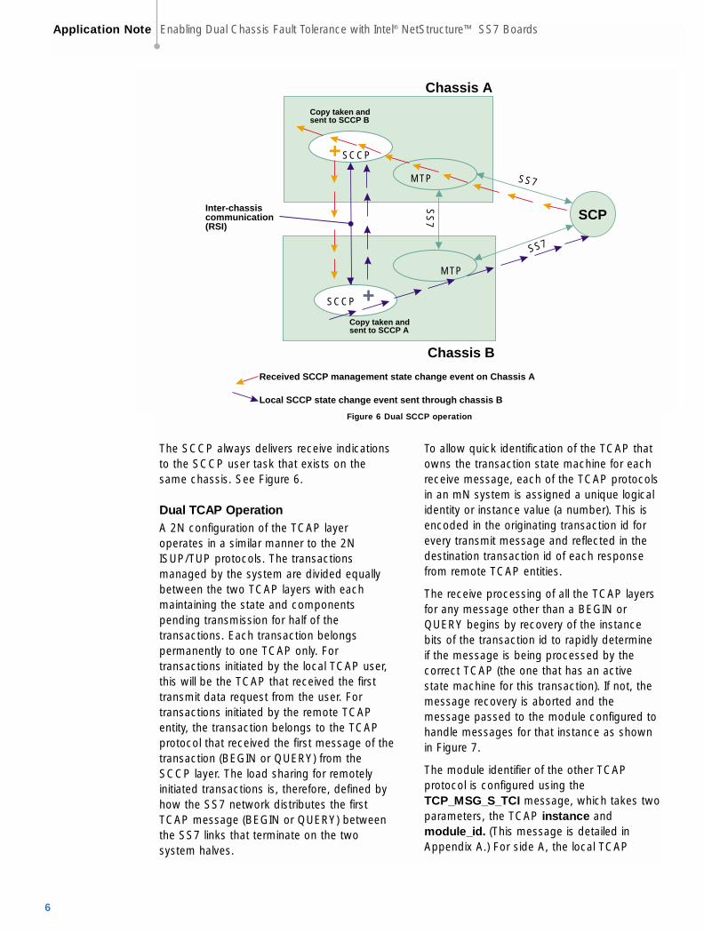
Figure 6 Dual SCCP operation
The SCCP always delivers receive indicationsto the SCCP user task that exists on thesame chassis. See Figure 6.
Dual TCAP OperationA 2N configuration of the TCAP layeroperates in a similar manner to the 2NISUP/TUP protocols. The transactionsmanaged by the system are divided equallybetween the two TCAP layers with eachmaintaining the state and componentspending transmission for half of thetransactions. Each transaction belongspermanently to one TCAP only. Fortransactions initiated by the local TCAP user,this will be the TCAP that received the firsttransmit data request from the user. Fortransactions initiated by the remote TCAPentity, the transaction belongs to the TCAPprotocol that received the first message of thetransaction (BEGIN or QUERY) from theSCCP layer. The load sharing for remotelyinitiated transactions is, therefore, defined byhow the SS7 network distributes the firstTCAP message (BEGIN or QUERY) betweenthe SS7 links that terminate on the twosystem halves.
To allow quick identification of the TCAP thatowns the transaction state machine for eachreceive message, each of the TCAP protocolsin an mN system is assigned a unique logicalidentity or instance value (a number). This isencoded in the originating transaction id forevery transmit message and reflected in thedestination transaction id of each responsefrom remote TCAP entities.
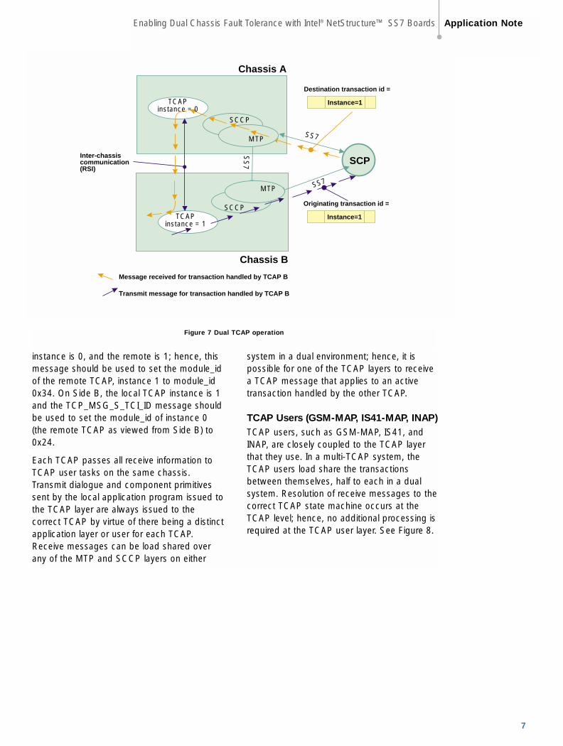
The receive processing of all the TCAP layersfor any message other than a BEGIN orQUERY begins by recovery of the instancebits of the transaction id to rapidly determineif the message is being processed by thecorrect TCAP (the one that has an activestate machine for this transaction). If not, themessage recovery is aborted and themessage passed to the module configured tohandle messages for that instance as shownin Figure 7.
The module identifier of the other TCAPprotocol is configured using theTCP_MSG_S_TCI message, which takes twoparameters, the TCAP instance and module_id. (This message is detailed inAppendix A.) For side A, the local TCAP
Application Note Enabling Dual Chassis Fault Tolerance with Intel® NetStructure™ SS7 Boards
6
SCP
SCCP
SS7
SS
7
SS7
Chassis A
Chassis B
SCCP
Inter-chassiscommunication(RSI)
Message received for transaction handled by TCAP B
Transmit message for transaction handled by TCAP B
MTP
MTP
Instance=1
Destination transaction id =
TCAPinstance = 0
TCAPinstance = 1
Instance=1
Originating transaction id =
Figure 7 Dual TCAP operation
instance is 0, and the remote is 1; hence, thismessage should be used to set the module_idof the remote TCAP, instance 1 to module_id0x34. On Side B, the local TCAP instance is 1and the TCP_MSG_S_TCI_ID message shouldbe used to set the module_id of instance 0(the remote TCAP as viewed from Side B) to0x24.
Each TCAP passes all receive information toTCAP user tasks on the same chassis.Transmit dialogue and component primitivessent by the local application program issued tothe TCAP layer are always issued to thecorrect TCAP by virtue of there being a distinctapplication layer or user for each TCAP.Receive messages can be load shared overany of the MTP and SCCP layers on either
system in a dual environment; hence, it ispossible for one of the TCAP layers to receivea TCAP message that applies to an activetransaction handled by the other TCAP.
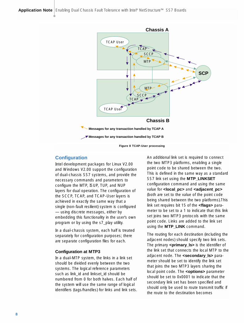
TCAP Users (GSM-MAP, IS41-MAP, INAP)TCAP users, such as GSM-MAP, IS41, andINAP, are closely coupled to the TCAP layerthat they use. In a multi-TCAP system, theTCAP users load share the transactionsbetween themselves, half to each in a dualsystem. Resolution of receive messages to thecorrect TCAP state machine occurs at theTCAP level; hence, no additional processing isrequired at the TCAP user layer. See Figure 8.
Enabling Dual Chassis Fault Tolerance with Intel® NetStructure™ SS7 Boards Application Note
7
SCP
Chassis A
Chassis B
Messages for any transaction handled by TCAP A
Messages for any transaction handled by TCAP B
MTP
TCAP
TCAP
SCCP
TCAP User
MTP
SCCP
TCAP User
Figure 8 TCAP-User processing
ConfigurationIntel development packages for Linux V2.00and Windows V2.00 support the configurationof dual-chassis SS7 systems, and provide thenecessary commands and parameters toconfigure the MTP, ISUP, TUP, and NUPlayers for dual operation. The configuration ofthe SCCP, TCAP, and TCAP-User layers isachieved in exactly the same way that asingle (non-fault resilient) system is configured— using discrete messages, either byembedding this functionality in the user’s ownprogram or by using the s7_play utility.
In a dual-chassis system, each half is treatedseparately for configuration purposes; thereare separate configuration files for each.
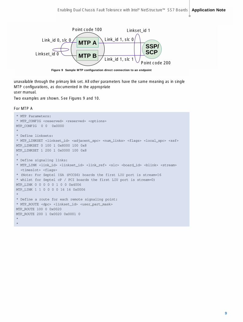
Configuration at MTP3In a dual-MTP system, the links in a link setshould be divided evenly between the twosystems. The logical reference parameterssuch as link_id and linkset_id should benumbered from 0 for both halves. Each half ofthe system will use the same range of logicalidentifiers (tags/handles) for links and link sets.
An additional link set is required to connectthe two MTP3 platforms, enabling a singlepoint code to be shared between the two.This is defined in the same way as a standardSS7 link set using the MTP_LINKSETconfiguration command and using the samevalue for <local_pc> and <adjacent_pc>(both are set to the value of the point codebeing shared between the two platforms).Thislink set requires bit 15 of the <flags> para-meter to be set to a 1 to indicate that this linkset joins two MTP3 protocols with the samepoint code. Links are added to the link setusing the MTP_LINK command.
The routing for each destination (including theadjacent nodes) should specify two link sets.The primary <primary_ls> is the identifier ofthe link set that connects the local MTP to theadjacent node. The <secondary_ls> para-meter should be set to identify the link setthat joins the two MTP3 layers sharing thelocal point code. The <options> parametershould be set to 0x0001 to indicate that thesecondary link set has been specified andshould only be used to route transmit traffic ifthe route to the destination becomes
Application Note Enabling Dual Chassis Fault Tolerance with Intel® NetStructure™ SS7 Boards
8
MTP A
MTP B
Point code 100
SSP/SCPLinkset_id 0
Linkset_id 1
Link_id 1, slc 0
Link_id 1, slc 1
Link_id 0, slc 0
Point code 200
Figure 9 Sample MTP configuration direct connection to an endpoint
unavailable through the primary link set. All other parameters have the same meaning as in singleMTP configurations, as documented in the appropriate user manual.
Two examples are shown. See Figures 9 and 10.
For MTP A
* MTP Parameters:
* MTP_CONFIG <reserved> <reserved> <options>
MTP_CONFIG 0 0 0x0000
*
* Define linksets:
* MTP_LINKSET <linkset_id> <adjacent_spc> <num_links> <flags> <local_spc> <ssf>
MTP_LINKSET 0 100 1 0x8000 100 0x8
MTP_LINKSET 1 200 1 0x0000 100 0x8
*
* Define signaling links:
* MTP_LINK <link_id> <linkset_id> <link_ref> <slc> <board_id> <blink> <stream>
<timeslot> <flags>
* (Note: For Septel ISA (PCCS6) boards the first LIU port is stream=16
* whilst for Septel cP / PCI boards the first LIU port is stream=0)
MTP_LINK 0 0 0 0 0 1 0 0 0x4006
MTP_LINK 1 1 0 0 0 0 16 16 0x0006
*
* Define a route for each remote signaling point:
* MTP_ROUTE <dpc> <linkset_id> <user_part_mask>
MTP_ROUTE 100 0 0x0020
MTP_ROUTE 200 1 0x0020 0x0001 0
*
*
Enabling Dual Chassis Fault Tolerance with Intel® NetStructure™ SS7 Boards Application Note
9

SSP/SCP
MTP A
MTP B
Linkset_id 1Point code300
Link set 0
STP
Linkset_id 1
Point code400
Point code500
Point code600
Link_id 0,slc 0
Link_id 1,slc 0
Link_id 1,slc 0
STP
Figure 10 Sample MTP configuration connection to STPs
For MTP B:
* MTP Parameters:
* MTP_CONFIG <reserved> <reserved> <options>
MTP_CONFIG 0 0 0x0000
*
* Define linksets:
* MTP_LINKSET <linkset_id> <adjacent_spc> <num_links> <flags> <local_spc> <ssf>
MTP_LINKSET 0 100 1 0x8000 100 0x8
MTP_LINKSET 1 200 1 0x0000 100 0x8
*
* Define signaling links:
* MTP_LINK <link_id> <linkset_id> <link_ref> <slc> <board_id> <blink> <stream>
<timeslot> <flags>
* (Note: For Septel ISA (PCCS6) boards the first LIU port is stream=16
* whilst for Septel cP / PCI boards the first LIU port is stream=0)
MTP_LINK 0 0 0 0 0 1 0 0 0x6006
MTP_LINK 1 1 0 1 0 0 16 16 0x0006
*
* Define a route for each remote signaling point:
* MTP_ROUTE <dpc> <linkset_id> <user_part_mask>
MTP_ROUTE 100 0 0x0020
MTP_ROUTE 200 1 0x0020 0x0001 0
*
*
Note that this does not include any commands to configure or define signaling cards. This shouldbe defined as if for a standard non-dual system. The MTP_ROUTE <up_enable> parameter wasset for ISUP, user part SI = 5 for the example above.
Application Note Enabling Dual Chassis Fault Tolerance with Intel® NetStructure™ SS7 Boards
10
Sufficient links should be provided in the linkset that joins the two MTP3 layers to givesufficient signaling bandwidth to allow all ofthe transmit traffic from one half to be routedthrough the second. The designer should alsonote that in order for one of the MTP3 halvesto begin transmitting traffic that would havebeen handled by its partner, each system halfshould not be loaded by more than 50% (bothprocessing and signaling channel bandwidth)under normal operating conditions. SS7systems are normally loaded at 20 to 40%maximum.
The inter-chassis links must be activated in thesame manner as other links connecting theplatform to remote SS7 nodes. This can beachieved using the mtpsl utility or by issuingan MTP link or link set activation commandmessage from the application program.
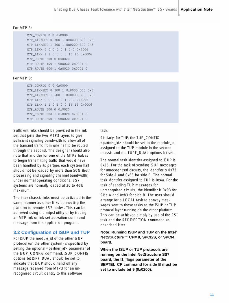
3.2 Configuration of ISUP and TUPFor ISUP the module_id of the other ISUPprotocol (on the other system) is specified bysetting the optional <partner_id> parameter ofthe ISUP_CONFIG command. ISUP_CONFIGoptions bit ISPF_DUAL should be set toindicate that ISUP should hand off anymessage received from MTP3 for an un-recognized circuit identity to this software
task.
Similarly, for TUP, the TUP_CONFIG<partner_id> should be set to the module_idassigned to the TUP module in the secondchassis and the TUPF_DUAL options bit set.
The normal task identifier assigned to ISUP is0x23. For the task of sending ISUP messagesfor unrecognized circuits, the identifier is 0x73for Side A and 0x63 for side B. The normaltask identifier assigned to TUP is 0x4a. For thetask of sending TUP messages forunrecognized circuits, the identifier is 0x93 forSide A and 0x83 for side B. The user shouldarrange for a LOCAL task to convey mes-sages sent to these tasks to the ISUP or TUPprotocol layer running on the other platform.This can be achieved simply by use of the RSItask and the REDIRECTION command asdescribed later.
Note: Running ISUP and TUP on the Intel®
NetStructure™ CPM8, SPCI2S, or SPCI4board.
When the ISUP or TUP protocols arerunning on the Intel NetStructure SS7board, the l1_flags parameter of theSEPTEL_CP command for side B must beset to include bit 9 (0x0200).
For MTP A:
MTP_CONFIG 0 0 0x0000
MTP_LINKSET 0 300 1 0x8000 300 0x8
MTP_LINKSET 1 400 1 0x0000 300 0x8
MTP_LINK 0 0 0 0 0 1 0 0 0x4006
MTP_LINK 1 1 0 0 0 0 16 16 0x0006
MTP_ROUTE 300 0 0x0020
MTP_ROUTE 400 1 0x0020 0x0001 0
MTP_ROUTE 600 1 0x0020 0x0001 0
For MTP B:
MTP_CONFIG 0 0 0x0000
MTP_LINKSET 0 300 1 0x8000 300 0x8
MTP_LINKSET 1 500 1 0x0000 300 0x8
MTP_LINK 0 0 0 0 0 1 0 0 0x6006
MTP_LINK 1 1 0 1 0 0 16 16 0x0006
MTP_ROUTE 300 0 0x0020
MTP_ROUTE 500 1 0x0020 0x0001 0
MTP_ROUTE 600 1 0x0020 0x0001 0
Enabling Dual Chassis Fault Tolerance with Intel® NetStructure™ SS7 Boards Application Note
11
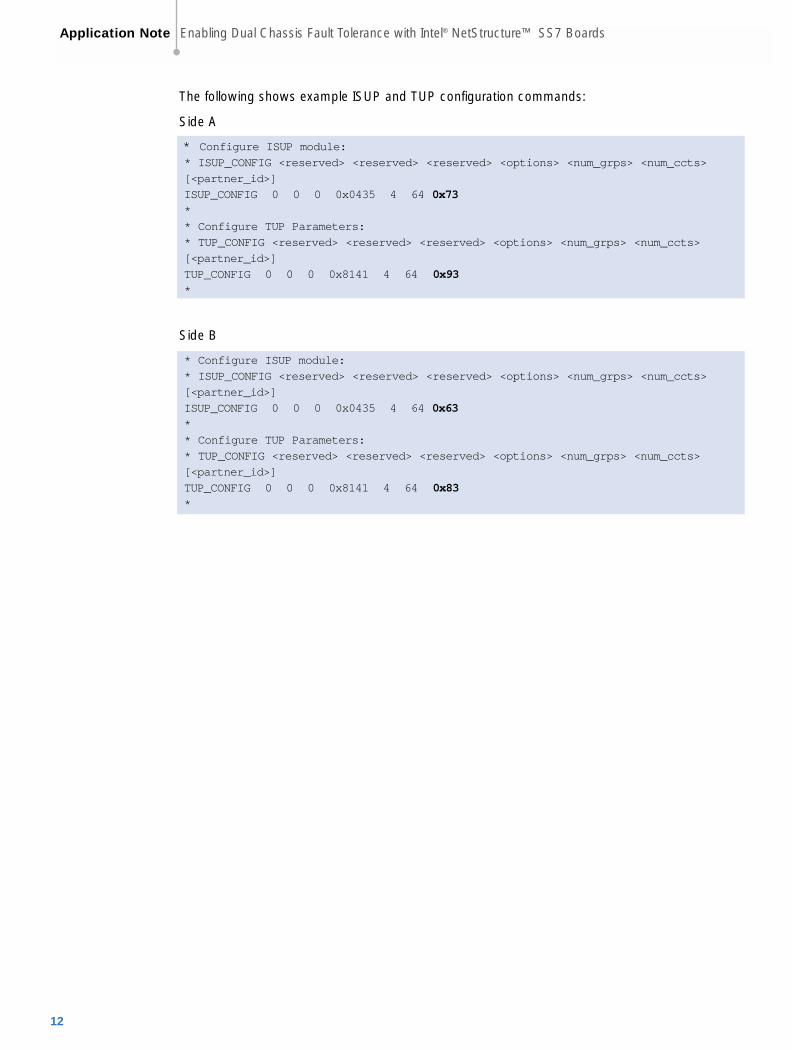
The following shows example ISUP and TUP configuration commands:
Side A
* Configure ISUP module:
* ISUP_CONFIG <reserved> <reserved> <reserved> <options> <num_grps> <num_ccts>
[<partner_id>]
ISUP_CONFIG 0 0 0 0x0435 4 64 0x73
*
* Configure TUP Parameters:
* TUP_CONFIG <reserved> <reserved> <reserved> <options> <num_grps> <num_ccts>
[<partner_id>]
TUP_CONFIG 0 0 0 0x8141 4 64 0x93
*
Side B
* Configure ISUP module:
* ISUP_CONFIG <reserved> <reserved> <reserved> <options> <num_grps> <num_ccts>
[<partner_id>]
ISUP_CONFIG 0 0 0 0x0435 4 64 0x63
*
* Configure TUP Parameters:
* TUP_CONFIG <reserved> <reserved> <reserved> <options> <num_grps> <num_ccts>
[<partner_id>]
TUP_CONFIG 0 0 0 0x8141 4 64 0x83
*
Application Note Enabling Dual Chassis Fault Tolerance with Intel® NetStructure™ SS7 Boards
12

Circuit group 0cid 1 to 31
ISUP/TUP A
Circuit group 1cid 33 to 63
E1 #1 CIC 1 to 31
Circuit group 2cid 65 to 95
Circuit group 3cid 97 to 127
E1 #3 CIC 65 to 95
E1 #5 CIC 129 to 159
E1 #7 CIC 193 to 223
Circuit group 0cid 1 to 31
ISUP/TUP B
Circuit group 1cid 33 to 63
E1 #2 CIC 33 to 63
Circuit group 2cid 65 to 95
Circuit group 3cid 97 to 127
E1 #4 CIC 97 to 127
E1 #6 CIC 161 to 191
E1 #8 CIC 224 to 254
Circuit group 1cid 1 to 31
ISUP/TUP A
Circuit group 3cid 33 to 63
E1 #1 CIC 1 to 31
Circuit group 5cid 65 to 95
Circuit group 7cid 97 to 127
E1 #3 CIC 65 to 95
E1 #5 CIC 129 to 159
E1 #7 CIC 193 to 223
Circuit group 0cid 1 to 31
ISUP/TUP B
Circuit group 2cid 33 to 63
E1 #2 CIC 33 to 63
Circuit group 4cid 65 to 95
Circuit group 6cid 97 to 127
E1 #4 CIC 97 to 127
E1 #6 CIC 161 to 191
E1 #8 CIC 224 to 254
Circuit group 0
Circuit group 2
Circuit group 4
Circuit group 6
Circuit group 1
Circuit group 3
Circuit group 5
Circuit group 7
Non used groups
Non used groups
Figure 11 Circuit group distribution – double capacity
Figure 12 Circuit group distribution – single capacity
The circuit groups can either be numbered starting at 0 for both systems, or gaps may be left on
each half where a circuit group exists on the other half. If the first method is used, the total system
capacity will be twice that of a single ISUP/TUP protocol layer; if the second, the total capacity will
be that of a single ISUP/TUP protocol layer. For both cases, each half will control separate CIC
ranges, as shown in Figures 11 and 12.
Enabling Dual Chassis Fault Tolerance with Intel® NetStructure™ SS7 Boards Application Note
13

The system that does not duplicate the circuitgroups between the two halves of the system(the “single capacity” system shown in Figure12) has the ability to activate (configure) theunused circuit groups on one of the halves ifthe other fails. This process is achieved usingthe xxx_MSG_CNF_GRP message to config-ure a circuit group. This will provide the SS7signaling resources and ISUP or TUP statemachines for the circuits that have failed onthe other unit. However, if the circuit termina-tions themselves remain physically connectedto the failed unit, the only process that thesignaling will be able to achieve for these cir-cuits is hardware blocking.
Configuration of SCCPAt the SCCP layer, each SCCP protocolshould be configured with identical local sub-system, remote signaling point, andremote sub-system data.
The smb_id configuration parameter is usedto identify the destination for status changeupdates, and should be set to the identity of atask that can convey this information to theother SCCP module in a dual system. In mostcircumstances, SCCP itself takes a taskidentifier of 0x33 and smb_id should be set to0x53 on Side A and 0x43 on Side B. AREDIRECTION statement set in the system.txtfile can then be used to route such messagesto the RSI or similar task, so that they aredelivered to the other SCCP layer connectedby an Ethernet. In addition, the SCCPsmb_flags configuration parameter should beset to 0x001c.
Configuration of TCAPIn a multi-TCAP environment, each TCAP isgiven a unique instance, which is encoded inthe transaction id at the SCCP boundary toallow quick resolution of the correctdestination TCAP for receive messages. Thefirst TCAP is normally given an instance valueof 0 and the next 1.
The tid_ninst parameter controls how manybits in the transaction id are used to encodethe instance data. In a dual system, 1 bit issufficient to distinguish between the two
TCAPs. (Note that tid_ndref must be largeenough to encode the highest dialogue_idvalue. In a system supporting 2048simultaneous dialogues a value of 11 orgreater must be used).
The logical dialogue_id ranges can be thesame for both TCAP halves (so that the twoapplication processes running on the twosystems both operate over the samedialogue_id range), or separate ranges can beused.
Inter Chassis CommunicationThe Resilient Socket Interface (RSI) softwaretakes all messages in its input queue thathave a destination other than that of the RSIitself and sends those to a peer RSI task onthe remote end of a TCP/IP Ethernet. Thecommunication uses TCP/IP sockets, oneside acting as a server and the other as aclient.
At the receiver, RSI takes messages receivedfrom the Ethernet and delivers them throughthe local message passing system to the taskidentified in the original message destination(header dst field). If the communicationbetween two RSI tasks over an Ethernet fails,messages passed to RSI for transmissionover the Ethernet are discarded.
The two RSI tasks running on the system (oneon each half) take the same unique module id,normally 0xb0. This must be declared in thesystem.txt file on both systems with a LOCALdefinition and started with a FORK_PROCESScommand. The RSI program takes its moduleid as an optional command line parameter,prefixed by ‘-m’, for example:
./rsi –m0xb0
Any message sent to the module id assignedto RSI will be processed by the local RSI taskand not passed over the Ethernet.
The RSI links between the master and eachslave host are activated using the rsicmdutility. The syntax for the rsicmd utility isshown below:
rsicmd <link_id> <conc_id> <link_type><rem_addr> <rem_port> [<rsi_id>]
Application Note Enabling Dual Chassis Fault Tolerance with Intel® NetStructure™ SS7 Boards
14

Connection type rem_addr ink_type value
Server IP address of Side B 0 (client)
Client 0 1 (server)
One side of the system needs to be configured as client, the other as server.
<rem_port> specifies the TCP/IP socket port that is used for the connection. Each RSIconnection (which will have a unique link_id) must take a unique port value, starting from 9000.
<rsi_id> Is optional and identifies the RSI module for message passing.
A REDIRECT statement must be inserted in the system.txt file for all destinations that areaccessible through the RSI connection to the other half of the system (the module_id value givento the second ISUP, TUP, SCCP, and/or TCAP protocol).
For example, a dual ISUP system will consist of two ISUP halves, each with a default module_id of0x23. The configuration data assigned to ISUP on Side A indicates the other ISUP half isaddressed as module_id 0x73; hence, there will be a redirection on Side A to redirect anymessages sent to 0x73 through RSI. On Side B, there should be a REDIRECT statement to routeall messages received by RSI on Side B for a destination 0x73 to the local ISUP, identified as 0x23.This is illustrated in Figure 13.
Figure 13 Use of REDIRECT and RSI for ISUP to ISUP communication
Send to ISUP BISUP (0x73)
RSI0xb0
ISUP0x23
REDIRECT 0x73 0xb0
ISUP0x23
Send to originaldestination
Chassis B
Chassis A
Ethernet
REDIRECT 0x73 0x23
RSI0xb0
<link_id> is a logical identifier for this particular communication channel. RSI selects an outgoingchannel by matching the message instance value (set by GCT_set_instance, which is zero bydefault) to the link_id value. For most dual systems, a single RSI connection between the twohalves will be sufficient, and this parameter should, therefore, be set to zero.
<conc_id> specifies a module ID that will receive notification (a message) whenever the specifiedRSI connection fails. This can be set to direct these indications to the application task or a localmanagement event viewer, such as s7_log.
<link_type> and <rem_addr> should be set according to the following table:
Enabling Dual Chassis Fault Tolerance with Intel® NetStructure™ SS7 Boards Application Note
15

Send to ISUP BISUP (0x73)
RSI0xb0ISUP
0x23
REDIRECT 0x73 0xb0
ISUP0x23
Chassis B
Chassis A
Ethernet
REDIRECT 0x73 0x20
RSI0xb0
SSD0x20
SSD0x20
Figure 14 Use of REDIRECT with SSD
Module Side A Setting Side B Setting
Local ISUP 0x23 0x23
Partner ISUP 0x73 0x63
Local TUP 0x4a 0x4a
Partner TUP 0x93 0x83
Local SCCP 0x33 0x33
Partner SCCP 0x53 0x43
Local TCAP 0x14 0x14
Partner TCAP 0x34 0x24
Local MAP 0x15 0x15
Local IS41 0x25 0x25
Local INAP 0x35 0x35
Where the protocol modules run on a signaling card, the REDIRECT statement at the receiver (thepartner side) should redirect messages through the ssd or ssds driver (normally taking the mod-ule_id 0x20), as shown in Figure 14.
The following table gives the module_id values that should be used on both sides of the system.
Application Note Enabling Dual Chassis Fault Tolerance with Intel® NetStructure™ SS7 Boards
16
Considerations for a ResilientApplication
In a dual system where the SS7 interface isembedded with the application, failure of theapplication or the SS7 components results incomplete failure of that half of the system.
In a dual circuit switching application (usingISUP or TUP), the physical circuit terminationsare distributed between the two chassis thatconstitute the system; hence, failure of one ofthe halves will result in the physical failure ofone half of the circuits. In SS7 terms, hardwarefailure is normally handled by issuing hardwareblocking (also known as blocking with release).This tears down all the active calls on theaffected circuits and indicates that thesecircuits should not be reselected for calls untilan unblocking operation has occurred, whichis done once the circuits had recovered.
However, in the configuration described earlier,the surviving half of the system will have noknowledge of the failed circuits (the configura-tion data for these would be held in the failedhalf), and would, therefore, not be able toissue hardware blocking. One method forsolving this is to use the circuit groupconfiguration method that leaves holes or gapswhere a circuit group exists on the other half.Following a failure of one half, these ‘ghost’circuit groups may be configured on thesurviving half, enabling hardware blocking tobe issued for circuits physically connected tothe failed chassis.
It is also possible to physically isolate theapplication media/circuit processing and SS7protocol state information, thereby enablingboth applications to communicate with bothSS7 interfaces (this is the approach taken bythe SIU). Physical isolation may be achievedby the use of RSI and Ethernet.
If required, the applications may check pointeach other to detect failures using themessage based API and RSI/Ethernet forcommunication. A user specific message mustbe defined for this purpose.
In a dual TCAP system, failure of one half ofthe system will result in loss of the TCAP stateinformation (for example, transaction state andany saved components pending transmission).In an Intelligent Networking environment, thecall associated with this transaction should, ifpossible, be released. In a mobile/wirelessenvironment, any associated pending mobileservice (such as short messaging) will timeout, and the operation will be reported asfailed. The operation should then bereattempted on the surviving system half.
The applications that communicate with theSS7 protocols must operate over the logicalcircuit id and dialogue id ranges pre-configured on each SS7 half. The twosystem halves can either use the same rangeof values since these are only private withineach half, or the two halves can operate overdifferent ranges.
Enabling Dual Chassis Fault Tolerance with Intel® NetStructure™ SS7 Boards Application Note
17

RSI0xb0
Chassis BChassis A
RSI0xb0
ISUP= 0x23ISUP-B= 0x73
SCCP=0x33SCCP-B=0x53
TUP=0x4aTUP-B=0x93
MTP0x22
TCAP=0x14TCAP-B=0x34instance = 0
ISUP= 0x23ISUP-A= 0x63
SCCP=0x33SCCP-A=0x43
TUP=0x4aTUP-A=0x83
TCAP=0x14TCAP-A=0x24instance = 0
MTP0x22
Figure 15 Modules in a dual SS7 protocol system
Application Note Enabling Dual Chassis Fault Tolerance with Intel® NetStructure™ SS7 Boards
18
Setting System.txt ValuesThe following diagram shows the relationship between the modules in a dualISUP/TUP/SCCP/TCAP system, alongside the appropriate entries in the config.txt files for bothhalves of the system. See Figure 15 for an illustration.
System.txt for Protocols Running on the Host
Side A
REDIRECT 0x34 0xb0 * TCAP to chassis B
REDIRECT 0x53 0xb0 * SCCP to chassis B
REDIRECT 0x73 0xb0 * ISUP to chassis B
REDIRECT 0x93 0xb0 * TUP to chassis B
*
REDIRECT 0x24 0x14 * TCAP from chassis B
REDIRECT 0x43 0x33 * SCCP from chassis B
REDIRECT 0x63 0x23 * ISUP from chassis B
REDIRECT 0x83 0x4a * TUP from chassis B

Side B
REDIRECT 0x24 0xb0 * TCAP to chassis A
REDIRECT 0x43 0xb0 * SCCP to chassis A
REDIRECT 0x63 0xb0 * ISUP to chassis A
REDIRECT 0x83 0xb0 * TUP to chassis A
*
REDIRECT 0x34 0x14 * TCAP from chassis A
REDIRECT 0x53 0x33 * SCCP from chassis A
REDIRECT 0x73 0x23 * ISUP from chassis A
REDIRECT 0x93 0x4a * TUP from chassis A
The system.txt file must also contain LOCAL definitions for all local SS7 protocols running on thehost such as ISUP, TUP, SCCP, or TCAP (if any), application tasks, configuration utilities (such ass7_mgt), and debug utilities. There should also be FORK_PROCESS statements to start theappropriate drivers and support tasks, as detailed in the appropriate programmers manual.
System.txt for Protocols Running on a Signaling Processor CardSide A
REDIRECT 0x34 0xb0 * TCAP to chassis B
REDIRECT 0x53 0xb0 * SCCP to chassis B
REDIRECT 0x73 0xb0 * ISUP to chassis B
REDIRECT 0x93 0xb0 * TUP to chassis B
*
REDIRECT 0x24 0x20 * TCAP from chassis B through ssd
REDIRECT 0x43 0x20 * SCCP from chassis B through ssd
REDIRECT 0x63 0x20 * ISUP from chassis B through ssd
REDIRECT 0x83 0x20 * TUP from chassis B through ssd
Side B
REDIRECT 0x24 0xb0 * TCAP to chassis A
REDIRECT 0x43 0xb0 * SCCP to chassis A
REDIRECT 0x63 0xb0 * ISUP to chassis A
REDIRECT 0x83 0xb0 * TUP to chassis A
*
REDIRECT 0x34 0x20 * TCAP from chassis A through ssd
REDIRECT 0x53 0x20 * SCCP from chassis A through ssd
REDIRECT 0x73 0x20 * ISUP from chassis A through ssd
REDIRECT 0x93 0x20 * TUP from chassis A through ssd
The system.txt file must also contain LOCAL definitions for all application tasks, configurationutilities (such as s7_mgt), and debug utilities. There should also be FORK_PROCESS statements tostart the appropriate drivers and support tasks, as detailed in the appropriate programmersmanual.
Enabling Dual Chassis Fault Tolerance with Intel® NetStructure™ SS7 Boards Application Note
19

MESSAGE HEADER
FIELD NAME MEANING
Type TCP_MSG_S_TCI_ID (0x5794)
Id Instance
src Sending module_id
dst TCP_TASK_ID (0x14)
rsp_req Used to request a confirmation
class 0
status 0
err_info 0
len 1
PARAMETER AREA
OFFSET SIZE NAME
0 1 module_id
Parameter Description:
InstanceThe instance value set in the transaction ID of any received message that should be sent to thespecified module_id.
module_idThe module_id to be used as the message destination when TCAP sends messages for thespecified instance.
Appendix A — TCAP Set Instance Module ID Message
Description:This message configures the module_id for a specific TCAP instance. This module_id will be usedby TCAP as the destination when sending any message received from the network with thespecified instance encoded in the transaction id.
Message Format:
Application Note Enabling Dual Chassis Fault Tolerance with Intel® NetStructure™ SS7 Boards
20
To learn more, visit our site on the World Wide Web at http://www.intel.com
1515 Route TenParsippany, NJ 07054Phone: 1-973-993-3000Fax: 1-973-993-3093
Information in this document is provided in connection with Intel® products. No license, express or implied, by estoppel orotherwise, to any intellectual property rights is granted by this document. Except as provided in Intel's Terms and Conditions of Salefor such products, Intel assumes no liability whatsoever, and Intel disclaims any express or implied warranty, relating to sale and/oruse of Intel® products including liability or warranties relating to fitness for a particular purpose, merchantability, or infringement ofany patent, copyright or other intellectual property right. Intel® products are not intended for use in medical, life saving, or life sustaining applications. Intel may make changes to specifications and product descriptions at any time, without notice.
*Other names and brands may be claimed as the property of others.
Performance tests and ratings are measured using specific computer systems and/or components and reflect the approximate per-formance of Intel products as measured by those tests. Any difference in system hardware or software design or configuration mayaffect actual performance. Buyers should consult other sources of information to evaluate the performance of systems orcomponents they are considering purchasing. For more information on performance tests and on the performance of Intel products,reference http://www.intel.com/procs/perf/limits.htm or call (U.S.) 1-800-628-8686 or 1-916-356-3104.
Intel, Intel NetStructure, and the Intel logo are trademarks or registered trademarks of Intel Corporation or its subsidiaries in theUnited States and other countries.
Printed in the USA Copyright © 2002 Intel Corporation All rights reserved. e Printed on recycled paper. 03/03 00-8459-002