enabling network throughput performance tests and statistical
TRANSCRIPT

TECHNICAL REPORT
© The Broadband Forum. All rights reserved.
TR-143 Enabling Network Throughput Performance Tests and
Statistical Monitoring
Issue: 1 Amendment 1
Issue Date: December 2014

Enabling Network Throughput Performance Tests and Statistical Monitoring TR-143 Issue 1
Amendment 1
December 2014 © The Broadband Forum. All rights reserved. 2
Notice
The Broadband Forum is a non-profit corporation organized to create guidelines for broadband
network system development and deployment. This Broadband Forum Technical Report has
been approved by members of the Forum. This Broadband Forum Technical Report is not
binding on the Broadband Forum, any of its members, or any developer or service provider. This
Broadband Forum Technical Report is subject to change, but only with approval of members of
the Forum. This Technical Report is copyrighted by the Broadband Forum, and all rights are
reserved. Portions of this Technical Report may be copyrighted by Broadband Forum members.
THIS SPECIFICATION IS BEING OFFERED WITHOUT ANY WARRANTY
WHATSOEVER, AND IN PARTICULAR, ANY WARRANTY OF NONINFRINGEMENT IS
EXPRESSLY DISCLAIMED. ANY USE OF THIS SPECIFICATION SHALL BE MADE
ENTIRELY AT THE IMPLEMENTER'S OWN RISK, AND NEITHER the Forum, NOR ANY
OF ITS MEMBERS OR SUBMITTERS, SHALL HAVE ANY LIABILITY WHATSOEVER
TO ANY IMPLEMENTER OR THIRD PARTY FOR ANY DAMAGES OF ANY NATURE
WHATSOEVER, DIRECTLY OR INDIRECTLY, ARISING FROM THE USE OF THIS
SPECIFICATION.
Broadband Forum Technical Reports may be copied, downloaded, stored on a server or
otherwise re-distributed in their entirety only, and may not be modified without the advance
written permission of the Broadband Forum.
The text of this notice must be included in all copies of this Broadband Forum Technical Report.

Enabling Network Throughput Performance Tests and Statistical Monitoring TR-143 Issue 1
Amendment 1
December 2014 © The Broadband Forum. All rights reserved. 3
TR Issue History
Issue Number Approval
Date
Publication
Date
Issue Editor Changes
1 May 2008 Tim Spets, Westell
Larry Jones, Verizon
Richard Jia, Verizon
Greg Bathrick, PMC-
Sierra
Original
Corrigendum 1 December
2008
Tim Spets, Westell
Remove
TCPOpenRequestTime and
TCPOpenResponseTime
from Download and
Upload profiles to fix
editorial mistake. Also 2
typos fixed.
Replaces TR-143 Issue 1
(May 2008)
Amendment 1 1 December
2014
11 February
2015
Sharam Hakimi,
EXFO
Steve Nicolai, Arris
Added:
UDPEchoPlus client
initiated testing.
Time base in addition to
file size,
Multi
Threading/Connections.
Server Diagnostics.
IPv4/IPv6 protocol
selection.
Comments or questions about this Broadband Forum Technical Report should be directed to
Editors
Sharam Hakimi
Steven Nicolai
EXFO
Arris
BroadbandHome
WG Chairs
Jason Walls
John Blackford
QA Café
Pace

Enabling Network Throughput Performance Tests and Statistical Monitoring TR-143 Issue 1
Amendment 1
December 2014 © The Broadband Forum. All rights reserved. 4
TABLE OF CONTENTS
EXECUTIVE SUMMARY .......................................................................................................... 6
1 PURPOSE AND SCOPE ...................................................................................................... 7
1.1 PURPOSE .......................................................................................................................... 7
1.2 SCOPE .............................................................................................................................. 7
2 REFERENCES AND TERMINOLOGY ............................................................................ 8
2.1 CONVENTIONS ................................................................................................................. 8 2.2 REFERENCES .................................................................................................................... 9 2.3 DEFINITIONS .................................................................................................................... 9
2.4 ABBREVIATIONS ............................................................................................................ 10
3 TECHNICAL REPORT IMPACT ................................................................................... 11
3.1 ENERGY EFFICIENCY ...................................................................................................... 11 3.2 IPV6 ............................................................................................................................... 11 3.3 SECURITY ....................................................................................................................... 11 3.4 PRIVACY ........................................................................................................................ 11
4 ACTIVE MONITORING .................................................................................................. 12
4.1 CPE INITIATED DIAGNOSTICS ......................................................................................... 13
4.2 NETWORK INITIATED DIAGNOSTICS ................................................................................ 14 4.3 TIME BASED THROUGHPUT TESTING ............................................................................... 15 4.4 MULTI-THREADING/CONNECTIONS ............................................................................... 16
5 PARAMETER DEFINITIONS ......................................................................................... 17
APPENDIX A: THEORY OF OPERATIONS ........................................................................ 18
A.1 CLIENT AND NETWORK INITIATED UDPECHODIAGNOSTICS ......................................... 18 A.1.1 Introduction........................................................................................................... 18
A.1.2 Motivation ............................................................................................................. 18 A.1.3 Security Considerations – Network initiated tests ................................................ 19
A.1.4 UDPEchoPlus Packet format ............................................................................... 19 A.1.5 UDPEcho and UDPEchoPlus server setup. ......................................................... 20
A.1.6 UDPEchoPlus Client ............................................................................................ 20 A.1.7 UDPEchoPlus server ............................................................................................ 20 A.1.8 Performance Metrics examples with UDPEchoPlus ............................................ 21
A.2 DOWNLOADDIAGNOSTICS UTILIZING FTP TRANSPORT ................................................. 25 A.3 UPLOADDIAGNOSTICS UTILIZING FTP TRANSPORT ....................................................... 29
A.4 DOWNLOADDIAGNOSTICS UTILIZING HTTP TRANSPORT ............................................... 33 A.5 UPLOADDIAGNOSTICS UTILIZING HTTP TRANSPORT ..................................................... 35
A.6 TIME BASED FILE TRANSFER (HTTP/FTP) .................................................................... 37 A.7 USE OF MULTI THREADING/CONNECTIONS .................................................................... 39
A.7.1 File Transfer Mode ............................................................................................... 39 A.7.2 Time Based Transfer Mode ................................................................................... 40 A.7.3 Period of Full Loading.......................................................................................... 41
A.8 SERVERSELECTIONDIAGNOSTICS .................................................................................. 41

Enabling Network Throughput Performance Tests and Statistical Monitoring TR-143 Issue 1
Amendment 1
December 2014 © The Broadband Forum. All rights reserved. 5
APPENDIX B: TEST RESULTS .............................................................................................. 42
B.1 UPLOADDIAGNOSTICS AND DOWNLOADDIAGNOSTICS TEST RESULTS .......................... 42 B.2 ASYMMETRICAL CONSIDERATIONS ................................................................................ 43
List of Figures
Figure 1 Performance Testing Components ................................................................................. 12 Figure 2 CPE DownloadDiagnostics using HTTP transport. ....................................................... 14 Figure 3 UDPEchoPlus Event Sequence ...................................................................................... 24 Figure 4 DownloadDiagnostics using FTP transport .................................................................... 28
Figure 5 UploadDiagnostics utilizing FTP transport .................................................................... 32 Figure 6 DownloadDiagnostics utilizing HTTP transport ............................................................ 35
Figure 7 UploadDiagnostics utilizing HTTP transport ................................................................. 37
Figure 8 CPE Time based throughput diagnostics using HTTP/FTP transport. ........................... 38 Figure 9 Time Based Multi Thread/Connection Testing .............................................................. 40 Figure 10 Multi Thread/Connection Total/Full Loading Time Duration ..................................... 41
List of Tables
Table 1 Enabling Network Throughput Performance Tests and Statistical Monitoring Versions 17
Table 2 Enabling Network Throughput Performance Tests and Statistical Monitoring Object
Usage..................................................................................................................................... 17 Table 3 UDPEchoPlus packet format ........................................................................................... 19
Table 4 Statistics and Protocol layer reference for FTP DownloadDiagnostics ........................... 26
Table 5 Statistics and Protocol layer reference for FTP UploadDiagnostics ................................ 29 Table 6 Statistics and Protocol layer reference for HTTP DownloadDiagnostics ........................ 33 Table 7 Statistics and Protocol layer reference for HTTP UploadDiagnostics ............................ 35
Table 8 Diagnostics Test Results .................................................................................................. 42

Enabling Network Throughput Performance Tests and Statistical Monitoring TR-143 Issue 1
Amendment 1
December 2014 © The Broadband Forum. All rights reserved. 6
Executive Summary
TR-143 Issue 1 Amendment 1 defines the CPE data model objects for Network Service
Providers to initiate performance throughput tests and monitor data on the IP interface of a CPE
using the Diagnostic mechanism defined in TR-069 [1].
The Network Service Provider provides network infrastructure and services to its customers,
these include Content Service Providers who source the information and end users who consume
that information. In order to minimize the downtime of network services, the Network Service
Provider needs tools to enable monitoring the performance of the network continuously to
prevent problems from occurring and diagnose the problem when it occurs.
The architecture of TR-069 [1] enables device management with the CPE devices both at the
customer’s gateway, and with devices within the customer’s office/home network. The
diagnostic and monitoring objects provided with TR-143 Issue 1 Amendment 1 will assist the
Network Service Provider in determining whether the problem occurs in the Network Service
Provider’s network or the customer’s office/home network.

Enabling Network Throughput Performance Tests and Statistical Monitoring TR-143 Issue 1
Amendment 1
December 2014 © The Broadband Forum. All rights reserved. 7
1 Purpose and Scope
1.1 Purpose
As broadband Network Service Providers endeavor to provide quantitative QoS and/or
qualitative QoS distinctions, they require some means of base lining nominal service levels and
validating such QoS objectives. Active Monitoring of the broadband access network represents
one important tool for achieving this objective. The key benefit of Active Monitoring is that it
allows the network operator to characterize the performance of end to end paths and/or path
segments depending on the scope of the probing. An example use case is to perform active tests
between the subscriber CPE and a Network Test Server located at the Network Service
Provider’s Point of Presence (POP). This scenario gives the Network Service Provider the ability
to measure the contribution of the Network Service Provider network (i.e. the portion of the end
to end path under the provider’s control) to the overall user experience (which is dictated by the
composite effect of the segments their applications traverse end to end). A natural extension of
this use case is to place Network Test Servers at multiple locations in the subscriber path towards
the provider’s Internet Peering Point. Moreover, Active Monitoring enables the measurement of
performance metrics conducive to establishing Service Level Agreements for guaranteed and
business class service offerings.
The throughput tests proposed in this Technical Report are intended to measure the user
experience via traffic emulation. Though it is arguable that the user experience can be inferred
solely from network performance parameters (e.g. packet loss, packet delay, etc.), network
operators can benefit from having the ability to measure user level performance metrics such as
transaction throughput and response time in a proactive or an on-demand basis. This Technical
Report includes throughput and response time test types in an overall portfolio of Active
Monitoring. Such tests inherently account for the nuances and n-th order effects of transport
protocol behavior such as TCP flow control by emulating application layer transactions (HTTP,
FTP) and explicitly measuring parameters of interest such as transaction throughput, round trip
time, and transaction response time. Since the network operator can bound the scope of the
measurement segment (e.g. to within a broadband access network or autonomous domain, etc.)
these measurements greatly enhance the performance characterization of network segments of
interest in a manner most intuitively aligned with the user experience. The set of test transaction
types here is extensible to other transaction types.
1.2 Scope
This Technical Report defines an Active Monitoring test suite which can be leveraged by
Network Service Providers to monitor and/or diagnose the state of their broadband network paths
serving populations of subscribers who utilize TR-069 compliant CPE. Active Monitoring
supports both Network Initiated Diagnostics and CPE Initiated Diagnostics for monitoring and
characterization of service paths in either an ongoing or on-demand fashion. These generic tools
provide a platform for the validation of QoS objectives and Service Level Agreements.
This Technical Report introduces a Network Test Server, which is a conceptual endpoint for the
testing described herein. Operation of this server is out of scope for this Technical Report.

Enabling Network Throughput Performance Tests and Statistical Monitoring TR-143 Issue 1
Amendment 1
December 2014 © The Broadband Forum. All rights reserved. 8
2 References and Terminology
2.1 Conventions
In this Technical Report, several words are used to signify the requirements of the specification. These
words are always capitalized. More information can be found be in RFC 2119 [6]
MUST This word, or the term “REQUIRED”, means that the definition is an
absolute requirement of the specification.
MUST NOT This phrase means that the definition is an absolute prohibition of the
specification.
SHOULD This word, or the term “RECOMMENDED”, means that there could exist
valid reasons in particular circumstances to ignore this item, but the full
implications need to be understood and carefully weighed before choosing a
different course.
SHOULD NOT This phrase, or the phrase "NOT RECOMMENDED" means that there could
exist valid reasons in particular circumstances when the particular behavior
is acceptable or even useful, but the full implications need to be understood
and the case carefully weighed before implementing any behavior described
with this label.
MAY This word, or the term “OPTIONAL”, means that this item is one of an
allowed set of alternatives. An implementation that does not include this
option MUST be prepared to inter-operate with another implementation that
does include the option.

Enabling Network Throughput Performance Tests and Statistical Monitoring TR-143 Issue 1
Amendment 1
December 2014 © The Broadband Forum. All rights reserved. 9
2.2 References
The following references are of relevance to this Technical Report. At the time of publication, the editions
indicated were valid. All references are subject to revision; users of this Technical Report are therefore
encouraged to investigate the possibility of applying the most recent edition of the references listed
below.
A list of currently valid Broadband Forum Technical Reports is published at
www.broadband-forum.org.
Document Title Source Year
[1] TR-069
Amendment 5
CPE WAN Management Protocol BBF 2013
[2] TR-098
Amendment 2
Internet Gateway Device Version 1.1 Data Model
for TR-069
BBF 2008
[3] TR-106
Amendment 7
Data Model Template for TR-069-Enabled
Devices
BBF 2013
[4] RFC 862 Echo Protocol IETF 1983
[5] RFC 959 File Transfer Protocol IETF 1985
[6] RFC 2119 Key words for use in RFCs to Indicate
Requirement Levels
IETF 1997
[7] RFC 2616 Hypertext Transfer Protocol -- HTTP/1.1 IETF 1999
[8] RFC 3393 IP Packet Delay Variation Metric for IP
Performance Metrics (IPPM)
IETF 2002
[9] RFC 3449 TCP Performance Implications of Network Path
Asymmetry
IETF 2002
[10] RFC 4291 IP Version 6 Addressing Architecture IETF 2006
[11] RFC 6349 Framework for TCP Throughput Testing IETF 2011
[12] TR-181i2a9 Device Data Model for TR-069 BBF 2013
2.3 Definitions
The following terminology is used throughout this Technical Report.
Active Monitoring Actively transmitting or receiving data in a controlled test.
Content Service Provider Provides services to the customer premise via the Network Service
Provider Network.
Internet Peering Point A location within the Network Service Provider network where the
Network Test Server is placed.
Network Service Provider Provides the broadband network between the customer premise and
the Internet.
Network Test Server Peer testing endpoint for the CPE within the Network Service
Provider network.

Enabling Network Throughput Performance Tests and Statistical Monitoring TR-143 Issue 1
Amendment 1
December 2014 © The Broadband Forum. All rights reserved. 10
Quality of Service Quality of service is the ability to provide different priority to
different applications, users, or data flows, or to guarantee a certain
level of performance to a data flow.
Service Level Agreement An agreement between the Network Service Provider and the Content
Service Provider to insure Quality of Service.
UDP Echo Service Services that ‘echoes’ a UDP packet back to the originator.
UDP Echo Plus Service Extension to UDP Echo Service defined in RFC 862 [4]
2.4 Abbreviations
This Technical Report defines the following abbreviations:
CPE Customer Premise Equipment
DoS Denial of Service
FTP File Transfer Protocol
HTTP Hypertext Transfer Protocol
ICMP Internet Control Message Protocol
IPDV IP Delay Variation
POP Point of Presence
QoS Quality of Service
RG Residential Gateway
TCP Transmission Control Protocol
TR Technical Report
UDP User Datagram Protocol
WG Working Group

Enabling Network Throughput Performance Tests and Statistical Monitoring TR-143 Issue 1
Amendment 1
December 2014 © The Broadband Forum. All rights reserved. 11
3 Technical Report Impact
3.1 Energy Efficiency
TR-143 Amendment 1 has no impact on energy efficiency.
3.2 IPv6
TR-143 Amendment 1 supports IPv6 [10] addressing.
3.3 Security
TR-143 Amendment 1 has no impact on security.
3.4 Privacy
Any issues regarding privacy are not affected by TR-143 Amendment 1.
Enabling Network Throughput Performance Tests and Statistical Monitoring TR-143 Issue 1
Amendment 1
December 2014 © The Broadband Forum. All rights reserved. 12
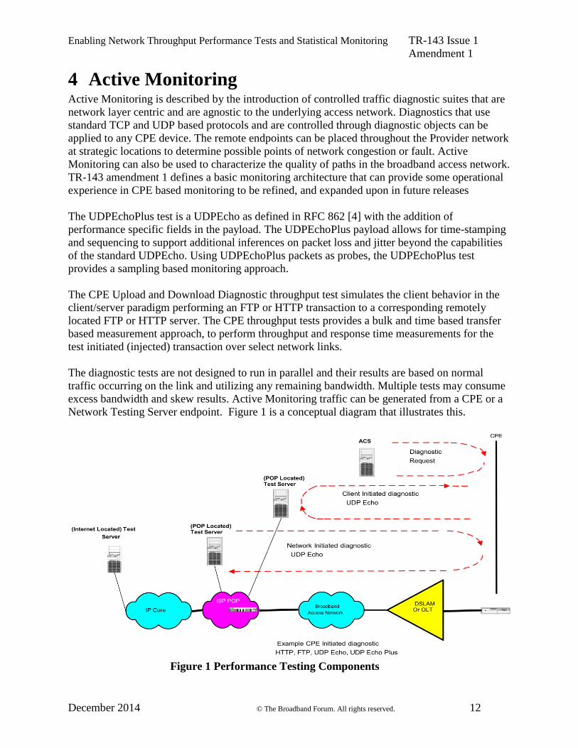
4 Active Monitoring Active Monitoring is described by the introduction of controlled traffic diagnostic suites that are
network layer centric and are agnostic to the underlying access network. Diagnostics that use
standard TCP and UDP based protocols and are controlled through diagnostic objects can be
applied to any CPE device. The remote endpoints can be placed throughout the Provider network
at strategic locations to determine possible points of network congestion or fault. Active
Monitoring can also be used to characterize the quality of paths in the broadband access network.
TR-143 amendment 1 defines a basic monitoring architecture that can provide some operational
experience in CPE based monitoring to be refined, and expanded upon in future releases
The UDPEchoPlus test is a UDPEcho as defined in RFC 862 [4] with the addition of
performance specific fields in the payload. The UDPEchoPlus payload allows for time-stamping
and sequencing to support additional inferences on packet loss and jitter beyond the capabilities
of the standard UDPEcho. Using UDPEchoPlus packets as probes, the UDPEchoPlus test
provides a sampling based monitoring approach.
The CPE Upload and Download Diagnostic throughput test simulates the client behavior in the
client/server paradigm performing an FTP or HTTP transaction to a corresponding remotely
located FTP or HTTP server. The CPE throughput tests provides a bulk and time based transfer
based measurement approach, to perform throughput and response time measurements for the
test initiated (injected) transaction over select network links.
The diagnostic tests are not designed to run in parallel and their results are based on normal
traffic occurring on the link and utilizing any remaining bandwidth. Multiple tests may consume
excess bandwidth and skew results. Active Monitoring traffic can be generated from a CPE or a
Network Testing Server endpoint. Figure 1 is a conceptual diagram that illustrates this.
Figure 1 Performance Testing Components

Enabling Network Throughput Performance Tests and Statistical Monitoring TR-143 Issue 1
Amendment 1
December 2014 © The Broadband Forum. All rights reserved. 13
4.1 CPE initiated diagnostics
In a CPE initiated UploadDiagnostics, DownloadDiagnostics, UDPEchoDiagnostics, and
UDPEchoPlusDiagnostics, ServerSelectionDiagnostics the following endpoints perform the
following functions.
The ACS initiates a diagnostic request (UploadDiagnostics,DownloadDiagnostics,
UDPEchoDiagnostics, UDPEchoPlusDiagnostics, ServerSelectionDiagnostics) to the CPE,
setting test parameters and initiating the test. The CPE starts the request by sending the
necessary test messages to the test server, which will send the correct responses. After receiving
the responses the CPE stores the test results Figure 2 is an example diagram of a DownloadDiagnostics using an HTTP URL.

Enabling Network Throughput Performance Tests and Statistical Monitoring TR-143 Issue 1
Amendment 1
December 2014 © The Broadband Forum. All rights reserved. 14
Figure 2 CPE DownloadDiagnostics using HTTP transport.
4.2 Network initiated diagnostics
The Network initiated diagnostics represents an alternative approach to minimize the burden on
the ACS for Network Service Providers that want to support continual proactive monitoring of
samplings of CPE. For example, dedicated Network Test Servers distributed per serving area can
perform Network initiated diagnostics to continually characterize the state of broadband access
paths to samplings of subscribers and build performance trends on those paths. For the Network
Initiated diagnostics model, the ACS would first need to enable the CPE to function as a server
(UDPEchoConfig). For security the source IP address of the Network Test are the only requests
the CPE protocol servers will respond to. Defined in A.1, is the UDPEcho tests sourced by the
Network Test Server and responded to by the CPE UDPEcho server. In a Network initiated
UDPEcho test the following sequence is used to perform the test;
:
:
:
: : :
:
:
Network Test server
HTTP
server
TCP connection initiation
CPE
HTTP “Get” URL
HTTP 200 OK response with data
E.g, DownloadDiagnostics with HTTP URL
TCP Ack
TCP Data
:
:
:
:
Recording
statistics
EOMTime
BOMTime
ROMTime
ACS
HTTP client
Diagnostic Request within a CWMP session
End CWMP session
Inform with “8 Diagnostics Complete” event within a CWMP session
End CWMP session
Enabling Network Throughput Performance Tests and Statistical Monitoring TR-143 Issue 1
Amendment 1
December 2014 © The Broadband Forum. All rights reserved. 15
The ACS configures the CPE to enable the UDPEcho server. The Network Test Server initiates
the client request, and sends the UDPEcho packets. The CPE UDPEcho server responds to the
UDPEcho packets.
4.3 Time based throughput testing
The purpose of time based testing is to accommodate multiple network speeds with a fixed, time
duration test. This allows for specifying a specific time for running a specific throughput test and
report the results based on the number of bytes transmitted or received during that time.
Three parameters control the operation of the time based test:
TimeBasedTestDuration: Defines the duration of the test (1- 999 seconds).
Note:if (=0) indicates file size transfer.
TimeBasedTestMeasurementInterval: Defines an interval to capture the results while the
test is run.
TimeBasedTestMeasurementOffset: Defines the time to begin capturing results after the
test has started (to allow for slow start of file transfers).
The client MUST stop capturing data in the download test after the specified duration even if the
server continues to send data. In the upload case the client must stop sending data after the time
duration has expired. The connection MUST be closed by the client after the specified time has
elapsed. If the connection closes or errors occur during the data transfer time, then the test is not
considered successful. Errors after the connection has closed shall be discarded.
For the time based upload case the client will be in control of the duration of time that it sends
data to the server. The client will know how many bytes it has transferred during the specified
time period for calculating link performance.
For the time based download test, the configured URL may include the duration of time that a
server needs to send data to the client. The server would have to adjust the number of required
bytes to be sent based on its attached interface speed. A 30 second data transfer at 1Gbps link
speed will need 100x data size than a data transfer at 10 Mbps link speed.
The following are examples of communicating the time duration to the targeted server. One way
is through a unique file name that can be used to specify the time duration.
A filename having the form:
“dntimebasedmode_xxx.txt” may be used, for the download where xxx represents an
unsigned number of minimum seconds data is requested from the targeted server.
Another approach could be to use either of the following URL formats:
http://<ServerHostName>/<TimeBasePathName>?time=30
ftp://<ServerHostName>/<TimeBasePathName>/30

Enabling Network Throughput Performance Tests and Statistical Monitoring TR-143 Issue 1
Amendment 1
December 2014 © The Broadband Forum. All rights reserved. 16
to communicate the duration that data is expected for the test. This also instructs the server to
send data for a minimum of 30 seconds. In either approach, the server is required to send data for
at least the requested duration.
4.4 Multi-Threading/Connections
Single TCP connection tests have limitations which do not allow for higher rate throughput
testing easily. See RFC 6349 [11] for details. In order to increase the rate that a specific link can
be tested, multi-threading/connections capability is being added in TR-143 Amendment 1. This
allows for multiple concurrent TCP connections for a single throughput test. These tests can be
file sized or time based depending on the chosen mode.
The DownloadDiagnosticMaxConnections and UploadDiagnosticMaxConnections parameters
allow the target device to communicate the maximum number of connections for upload or
download that it supports and the NumberOfConnections parameter defines the number of
connections that should be used to perform the test. The number of connections should not
exceed the maximum number of connections that a target device supports with a default value=1.
The multi connection option keeps status and results for each connection individually. For a test
to be considered successful, all connections specified by the NumberOfConnections parameter
must be established and all connections must finish the test successfully. Any failure to connect
to any of the connections or failure to complete the test by any connection is considered a failure
for the test.

Enabling Network Throughput Performance Tests and Statistical Monitoring TR-143 Issue 1
Amendment 1
December 2014 © The Broadband Forum. All rights reserved. 17
5 Parameter Definitions The normative definition of the Enabling Network Throughput Performance Tests and
Statistical Monitoring object definitions is done with its own DM Instance documents (see TR-
106 [3] Annex A). Table 1 lists the DM Instance documents that had been defined at the time of
writing and gives links to the associated XML and HTML files.
Note that, because new minor versions of the data model can be defined without re-publishing
this Technical Report, the table is not necessarily up-to-date. An up-to-date version of the table
can always be found at http://www.broadband-forum.org/cwmp.
Table 1 Enabling Network Throughput Performance Tests and Statistical Monitoring Versions
Version DM Instance Technical
Report
XML and HTML
1.0 tr-143-1-0.xml TR-143 http://broadband-forum.org/cwmp/tr-143-1-0.xml
http://broadband-forum.org/cwmp/tr-143-1-0.html
1.1 tr-143-1-1.xml TR-143
Amendment 1
http://broadband-forum.org/cwmp/tr-143-1-1.xml
http://broadband-forum.org/cwmp/tr-143-1-1.html
Table 2 shows the usage of the component objects in the root data models:
Table 2 Enabling Network Throughput Performance Tests and Statistical Monitoring Object Usage
TR-143 Version DM Instance Root Model
1.0 tr-098-1-2.xml InternetGatewayDevice:1.4
1.0 tr-106-1-2.xml Device:1.2
1.0 tr-181-2-0.xml Device:2.0
1.1 tr-098-1-9.xml InternetGatewayDevice:1.14
1.1 tr-181-1-7.xml Device:1.13
1.1 tr-181-2-9.xml Device:2.9

Enabling Network Throughput Performance Tests and Statistical Monitoring TR-143 Issue 1
Amendment 1
December 2014 © The Broadband Forum. All rights reserved. 18
Appendix A: Theory of Operations
A.1 Client and Network Initiated UDPEchoDiagnostics
A.1.1 Introduction
The UDPEcho Service is defined by RFC 862 [4], UDPEchoPlus utilizes the UDPEcho Service
and extends it by additional packet field definitions and new server behaviors. The UDPEcho
server utilizes improved security provided by UDPEchoConfig object.
The network initiated test originates from a device on the network and the CPE is the server
(responder) and the Client initiated tests originate from the CPE to a server (responder) on the
network.
A.1.2 Motivation
The notion of active probe based sampling of network paths and/or path segments has long been
established as a viable methodology for making inferences on the state of such paths (and path
segments), with regard to link and network layer performance metrics such as packet/frame/cell
loss, delay, delay variation and others. A very useful tool for realizing probing and general
debugging (such as path continuity and integrity verification), is an echo service. In the link layer
context, OAM loopback messages such as defined ITU-T I.610, for the ATM case, have been
employed. In the IP context, ICMP echo (i.e. ping) has been widely used for such purposes due
to its ubiquitous availability in network routers and hosts. However, the viability of using ping
measurements suffers from the fact that many routers process pings with lower priority than
actual user packets and may delay or discard ICMP echo requests in a manner that skews the
measurement results. The UDPEcho Service is defined at the UDP (or TCP) port level rectifies
this issue (unless explicitly port filtered at an intermediate or end host or router). UDPEcho
packets traverse the same intermediate nodes and logical queuing paths as the user data traffic of
the same class of service. The class of service is dictated by DHCP code bit settings, etc. or other
network operator specific criteria.
UDPEchoPlus proposes extensions to UDPEcho for improved monitoring capabilities.
UDPEchoPlus is backwards compatible with UDPEcho and devices capable of supporting
UDPEchoPlus have no discernable effect on cooperating devices running standard UDPEcho.
However, when both cooperating devices are UDPEchoPlus capable, the utility of UDPEcho is
extended by the additional information provided in the five data fields specified in Table 1.
UDPEchoPlus provides additional capability beyond UDPEcho Service including:
The ability to discern which direction packet drops occur (i.e. one way packet loss per
each direction).
One way packet delay variation per each direction.
Capability of running multi iterations of a test for comparison, averaging or other post
collection processing.

Enabling Network Throughput Performance Tests and Statistical Monitoring TR-143 Issue 1
Amendment 1
December 2014 © The Broadband Forum. All rights reserved. 19
A.1.3 Security Considerations – Network initiated tests
A UDPEchoPlus Network initiated test requires the CPE device to respond to the UDPEcho
request on the defined interface(s). In order to prevent a DoS (Denial of Service) attack on the
CPE, the CPE will only respond to the UDP request from a Source address defined in
SourceIPAddress, and will only service the port defined in UDPPort.
A.1.4 UDPEchoPlus Packet format
The UDPEcho Plus packet contains the packet fields specified in Table 3. Each field is 4 bytes
(32 bits) each. Timestamps require a continuous wrapping 32 bit (Big Endian) counter that
begins on startup and counts in microseconds.
When a UDPEcho Plus capable service receives a standard UDPEcho packet, the UDPEchoPlus
server just reflects the request back towards the source with no payload modification.
UDPEcho requests packets have a minimum payload length of 24 bytes with the following
parameters in the payload.
Table 3 UDPEchoPlus packet format
Source
Port
Destination Port
Length Checksum
TestGenSN
TestRespSN
TestRespRecvTimeStamp
TestRespReplyTimeStamp
TestRespReplyFailureCount
TestIterationNumber
Data…
Note: Older versions that supported 20 bytes will treat the additional 4 bytes required by
the TestIterationNumber field as regular data and repeat it back the same as it was
transmitted.
TestGenSN – The packet’s sequence number set by the UDP client in the echo request
packet, and is left unmodified in the response. It is set to an initial value upon the first
requests and incremented by 1 for each echo request sent by the UDP client.
Note the initial value of TestGenSN is implementation specific.
TestRespSN – The UDPEchoPlus server’s count that is incremented upon each valid echo
request packet it received and responded to. This count is set to 0 when the UDPEcho server
is enabled.
TestRespRecvTimeStamp is set by the UDPEchoPlus server to record the reception time of
echo request packet and is sent back to the client in this data field of the echo response
packet.

Enabling Network Throughput Performance Tests and Statistical Monitoring TR-143 Issue 1
Amendment 1
December 2014 © The Broadband Forum. All rights reserved. 20
TestRespReplyTimeStamp is set by the UDPEchoPlus server to record the forwarding time
of the echo response packet.
TestRespReplyFailureCount is set by the UDPEchoPlus server to record the number of
locally dropped echo response packets. This count is incremented if a valid echo request
packet is received but for some reason can not be responded to (e.g. due to local buffer
overflow, CPU utilization, etc...). It is a cumulative count with its current value placed in all
request messages that are responded to. This count is set to 0 when the UDPEcho server is
enabled.
TestIterationNumber is the test number set by the UDPEchoPlus client to indicate the
specific test iteration number. This number has minimum value of 1 and a maximum value
equal to NumberOfRepetitions.
Note #1: The TestRespReplyFailureCount counter will roll over every 71.5 minutes. Every two
successive UDPEchoPlus packets used in the same test would need to be sent within that interval for
jitter computation (loss computation of course would not have this restriction).
Note #2: Devices that don't support 1usec timestamp resolution, will still compute the timestamp in
microseconds, providing a multiplier. For example a device with 1msec resolution, will increment
the 32bit timestamp field in steps of 1000 (instead of steps of 1).
A.1.5 UDPEcho and UDPEchoPlus server setup.
When enabled the UDPEcho or UDPEchoPlus server will accept UDPEcho or UDPEchoPlus
packets respectively and perform the specific operation in the following sections. All counters
are reset to 0 when enabled.
A.1.6 UDPEchoPlus Client
The UDPEcho client sends packets that match the UDPEchoPlus server configuration
(Destination and Source IP address, UDP port). The UDPEchoPlus client controls the provisional
settings such as DSCP code point settings, packet size and inter-arrival spacing. The
UDPEchoPlus client will place a 32 bit sequence number value, which increments by 1 for each
request packet sent, in the TestGenSN field of each UDPEchoPlus request.
Note: Unlike Bulk Data transfer tests, the UDPEcho and UDPEchoPlus tests are typically
performed to probe the state of the network at low sampling rates. The UDPEcho or Echo Plus
request stream is usually generated at a slow enough rate so that it has negligible impact on the
workloads seen by the network nodes the Echo packets traverse.
A.1.7 UDPEchoPlus server
After UDPEchoPlus server configuration and enabling, the UDPEchoPlus server waits for the
arrival of UDPEchoPlus (or regular UDPEcho) packets. The UDPEchoPlus server determines a
valid request by criteria specified in UDPEchoPlusConfig such as the source IP address of the
request, transport protocol and destination port number. An example reference behavior for a
UDPEchoPlus server is as follows.
1. The UDPEcho server determines that the UDPEchoPlus request is a valid request, if not, the
request is ignored.

Enabling Network Throughput Performance Tests and Statistical Monitoring TR-143 Issue 1
Amendment 1
December 2014 © The Broadband Forum. All rights reserved. 21
2. If the “valid echo request” criteria is met, the arrival time of the UDPEchoPlus request (i.e.
time the last bit of the packet is read from the media), is time stamped with
TestRespRecvTimeStamp.
3. The UDPEchoPlus server prepares a UDPEcho response packet with the data from the
request packet.
4. If the packet size is large enough to support the UDPEchoPlus data fields, then the first 24
bytes are populated according to Table 1:
TestGenSN is left unmodified.
TestRespSN is a sequence number maintained by the server which indicates the number
of requests that have been successfully responded to.
TestRespRecvTimeStamp is the timestamp recorded in step 2.
TestRespReplyTimeStamp is the timestamp indicating the time the last bit of the
response is placed on the physical media.
TestRespReplyFailureCount is the cumulative number of valid requests that the
UDPEcho Plus server could not respond to for whatever reason up to that point in time
since the server was enabled. (Due to processing, buffer resource limitations, etc.).
TestIterationNumber is left unmodified.
A.1.8 Performance Metrics examples with UDPEchoPlus
The metrics presented in the section are some examples of what can be inferred by
UDPEchoPlus measurements.
For all example metrics refer to the UDPEchoPlus event sequence diagram depicted in Figure 3.
This depicts the sequence of UDPEchoPlus requests and corresponding responses during time
interval Tstart to Tend. These time boundaries could correspond to the time duration which the
UDPEchoPlus server is provisioned to actively respond to request packets (i.e. the time period
for which UDPEchoPlus server is enabled).
Gsi, is the time the UDPEchoPlus client sends the UDPEchoPlus request.
Gri is the time the UDPEchoPlus client receives the UDPEchoPlus response.
Rri is the time the UDP Echo Plus server receives the UDPEchoPlus request
(TestRespRecvTimeStamp).
Rsi is the time the UDPEchoPlus server sends the UDPEchoPlus response
(TestRespReplyTimeStamp).
These are the timestamp values placed in the “i-th” UDPEchoPlus received by the UDPEchoPlus
server. In the following examples a UDPEchoPlus client and UDPEchoPlus server begin with
sequence numbers equal to 1. The UDPEchoPlus client may also require a successful round trip
of the UDPEchoPlus to give the proper sequence number offset.
A.1.8.1 One Way Packet Loss
The UDPEchoPlus client keeps a local tally of the number of request packets that were
successfully responded to (within some timer expiration threshold). Refer to this value as the
SucessfulEchoCnt. Then upon receiving a UDPEchoPlus response packet from the

Enabling Network Throughput Performance Tests and Statistical Monitoring TR-143 Issue 1
Amendment 1
December 2014 © The Broadband Forum. All rights reserved. 22
UDPEchoPlus server at some time Gri, the UDPEchoPlus client can determine
RoundTripPacketLoss as:
RoundTripPacketLoss = (TestGenSN – SuccessfulEchoCnt)
Sent packet loss (from UDPEchoPlus client to UDPEchoPlus server path) is determined by
subtracting the total requests received by the UDPEcho Plus server (TestRespSN) from the total
request sent by the UDPEchoPlus client (TestGenSN). The total request received by the
UDPEchoPlus server is conveyed to the UDPEchoplus client via the sum TestRespSN +
TestRespReplyFailureCount. Therefore upon receiving a UDPEchoPlus response packet from
the UDPEchoPlus server at some time Gri, the UDPEchoPlus client can determine:
Sent packet loss = TestGenSN – (TestRespSN + TestRespReplyFailureCount)
Receive packet loss (the UDPEchoPlus server to UDPEchoPlus client path Packet loss), can be
calculated upon receiving a UDPEchoPlus response packet from the UDPEchoPlus server at
some time Gri, by:
Receive packet loss = RoundTripPacketLoss – Sent packet loss
A.1.8.2 Round Trip Delay
Upon receiving a UDPEchoPlus response packet from the UDPEchoPlus server at some time
Gri, corresponding to the “i-th” request sent, like standard UDPEcho, a UDPEchoPlus client can
compute the Round Trip Delay (RTD) simply according to:
RTDi = Gri - Gsi
UDPEchoPlus capability allows for the removal of the UDPEchoPlus server’s delay component
from each RTD value and removes the processing delays at the UDPEchoPlus server. Denoting
the RTD measurements with UDPEchoPlus server delay contribution removed as Effective-
RTD, then at time Gri the UDPEchoPlus client can compute:
Effective-RTDi = Gri - Gsi – (TestRespReplyTimeStamp - TestRespRecvTimeStamp)
A.1.8.3 One Way IP Packet Delay Variation (IPDV)
UDP Echo Plus capability can also provide the computation of IPDV (IP Delay Variation)
singletons as defined in RFC 3393[8] for each direction to infer One Way IPDV statistics of a
time interval over which UDPEcho Plus is performed.
This is done by first defining GsPrevious ,GrPrevious, RrPrevious, RsPrevious as the times a previous
UDPEcho Plus round trip was successful, then comparing those time stamps against the current
successful round trip times stamps in the below calculations:
An IPDV singleton on the Sent path (from UDPEchoPlus client to UDPEchoPlus server)
measured at the UDPEchoPlus client at time Gri by

Enabling Network Throughput Performance Tests and Statistical Monitoring TR-143 Issue 1
Amendment 1
December 2014 © The Broadband Forum. All rights reserved. 23
Send time delta= Gsi - GsPrevious
Receive time delta = Rri – RrPrevious
Sent path IPDV (i) = Send time delta – Receive time delta
An IPDV singleton on the Receive path (from UDP EchoPlus server to UDPEchoPlus
client) measured at the UDPEchoPlus client at time Gri by
Response time delta = Rsi – RsPrevious
Receive time delta = Gri - GrPrevious
Receive path IPDV (i) = Response time delta – Receive time delta
A sequence of IPDV singletons calculations utilizing RFC 3393 may be applied to compute
IPDV statistics for each direction.

Enabling Network Throughput Performance Tests and Statistical Monitoring TR-143 Issue 1
Amendment 1
December 2014 © The Broadband Forum. All rights reserved. 24
Figure 3 UDPEchoPlus Event Sequence
Gs 1
Gs 2
Gs n
Gr 1
Gs 2
Gr n
Rr 1
Rs 1 UDP Echo plus response #1
UDP Echo plus request #1
UDP Echo plus response #2
UDP Echo plus request #2
UDP Echo plus response #n
UDP Echo plus request #n
T start
T End
Rr 2
Rs 2
Rr n
Rs n
UDP Echo plus client UDP Echo plus server

Enabling Network Throughput Performance Tests and Statistical Monitoring TR-143 Issue 1
Amendment 1
December 2014 © The Broadband Forum. All rights reserved. 25
A.1.8.4 Response Time
The UDPEchoPlus Client has the capability to run a number of iterations of a UDPEchoPlus test
specified by NumberOfRepetitions parameter. This allows a response time to be recorded for
every test iteration. The following are calculated based on the received response times:
MaximumResponseTime = Highest response time value of the test iterations
MinimumResponseTime = Lowest response time value of the test iterations
AverageResponseTime = ( ∑ 𝑹𝒆𝒔𝒑𝒐𝒏𝒔𝒆𝑻𝒊𝒎𝒆 )𝒊𝟏 / i
Note: Where (i) Is the number of Repetitions
A.1.8.5 Client Initiated UDPEchoPlus Server Overload Indication
The UDPEchoPlus Client keeps a success and failure count for each UDPEchoPlus transaction.
This is done through a specified timeout value for when a response is received or no response is
received. There are times that the Client Initiated UDPEchoPlus server receives the
UDPEchoPlus packet but is unable to respond to the Client Initiated UDPEchoPlus Client and
the received packet is dropped at the server due to internal loading issues (i.e. CPU utilization).
In these cases where the incoming UDPEchoPlus packets are dropped by the Client Initiated
UDPEchoPlus server, the server will record the number of dropped response packets and report
them in the Following Parameter:
TestRespReplyFailureCount: Number Of UDPEchoPlus Packet Response Dropped
The TestRespReplyFailureCount is reported on the next successful UDPEchoPlus packet
transaction between the Client and the Server. This is a rolling counter for the duration of the
test.
A.2 DownloadDiagnostics Utilizing FTP Transport
Note: The descriptions and conditions in this section apply to a single
connection and file sized based test only.
The DownloadDiagnostics test is being used to test the file size based streaming capabilities and
responses of the CPE and the WAN connection. The measurements are made during the
download process, the ‘files’ that are downloaded are arbitrary, and are only temporary. The file
received is a stream of arbitrary bytes of a specified length. There is no bound on file size.
The FTP, RFC 959 [5], server response to the FTP SIZE command gives the CPE the size of the
file being downloaded. The FTP server response to the FTP RFC 959 [5] RTRV command will
initiate the data sent on the FTP RFC 959 [5] data connection.
The CPE counts the number of file bytes received successfully and compares it to the response to
the FTP RFC 959 [5] SIZE command. The CPE is not required to retain the file in memory.

Enabling Network Throughput Performance Tests and Statistical Monitoring TR-143 Issue 1
Amendment 1
December 2014 © The Broadband Forum. All rights reserved. 26
Once the CPE has successfully received the number of file bytes specified in the FTP RFC 959
[5] SIZE command it must terminate the FTP control connection.
Table 4 Statistics and Protocol layer reference for FTP DownloadDiagnostics
Above Socket (FTP RFC
959)
Socket Layer Below Socket
ROMTime EOMTime TotalBytesReceived (Ethernet)
BOMTime EthernetPriority (Ethernet)
TCPOpenRequestTime DSCP setting (IP)
TCPOpenResponseTime
TestBytesReceived
For the DownloadDiagnostics test utilizing FTP transport, the FTP client emulates an FTP
download transaction to an FTP URL as specified by DownloadURL. A sequence of events and
corresponding actions are described below, reference of Figure 4.
1. Open a TCP socket for the FTP control connection.
2. Upon receiving the control connection response:
If a FTP positive response is received, send a FTP
USER command with user value
set to “anonymous” to indicate an anonymous user login is being request.
Error Condition - If a FTP negative response is received or a timeout has occurred, then set
DiagnosticsState to Error_InitConnectionFailed and terminate the test.
3. Upon receiving an “enter password” request:
Perform a PASS command using any string (e.g. “dummypwd@”) to be used as the
password for the anonymous login.
Error Condition -If the “enter password” request fails or times out, then set
DiagnosticsState to Error_PasswordRequestFailed and terminate the test.
4. Upon receiving a password response:
If the response was “successfully logged in”, then send a TYPE command with
argument character set to ‘I’ for binary mode.
Error Condition -If a “successfully logged in” is not received or the response times out,
then set DiagnosticsState to Error_LoginFailed and terminate the test.
5. Upon receiving an transfer mode response:
If the transfer mode was set successfully, send a PASV command to request the
server be placed in passive mode.

Enabling Network Throughput Performance Tests and Statistical Monitoring TR-143 Issue 1
Amendment 1
December 2014 © The Broadband Forum. All rights reserved. 27
Error Condition -If a transfer mode response fails or times out, then set DiagnosticsState to
Error_NoTransferMode and terminate the test.
6. Upon receiving passive mode response:
If the passive mode response is successful, request the establishment of the FTP data
connection.
Set TCPOpenRequestTime to the current time.
Error Condition -If a passive mode response fails or times out, then set DiagnosticsState to
Error_NoPASV and terminate the test.
7. Upon receiving the TCP data connection response: for the FTP date connection:
If it was successfully established then set TCPOpenResponseTime, equal to the
current time value.
Error Condition -If the connection could not be opened or times out, then set
DiagnosticsState to Error_NoResponse and terminate the test.
Send the SIZE command on the FTP control connection to obtain the size of the file
to be downloaded.
8. Upon receiving the response to the SIZE command:
Record the file size in bytes. Send a RTRV command to request the contents of the
file.
Set the ROMTime to the current time value.
Error Condition - If a valid response was not received from the server in response to the
SIZE command or a timeout has occurred, then set DiagnosticsState to Error_IncorrectSize
and terminate the test.
9. Upon receiving the first unit of data (at the socket interface) of the FTP data connection
(i.e. corresponding to the first segment of data in the file):
Set BOMTime equal to the current time value.
Record the current value of the Ethernet bytes received on the Interface, to be used
has reference later in TotalBytesReceived calculation.
Error Condition - If the FTP transfer times out, then set DiagnosticsState to Error_Timeout
and terminate the test.
10. Upon receiving the last packet of data on the FTP data connection (i.e. corresponding to
the last segment of data in the file):
Set EOMTime equal to the current time value.
Record the current value of the Ethernet bytes received on the Interface, and calculate
the TotalBytesReceived (using the previous value sampled at BOMTime).

Enabling Network Throughput Performance Tests and Statistical Monitoring TR-143 Issue 1
Amendment 1
December 2014 © The Broadband Forum. All rights reserved. 28
Note: In binary transfer mode, a count of the total bytes received at the socket level can
be maintained and compared to the file size obtained by the SIZE command in step #8
above.
11. Once the EOMTime is set:
Set DiagnosticsState to the Completed state.
The server closes the connection or sends a TCP RESET flag if a timeout occurs.
USER anonymous + ACK
SYN
SYN + ACK
ACK
220 FTP Server Ready
331 Enter Password + ACK
PASS dummypwd@ + ACK
230 User Logged In + ACK
TYPE I + ACK
200 Transfer Mode Set to Bin +
ACK
PASV + ACK
227 Entering Passive Mode + ACK
SYN
SYN + ACK
ACK
SIZE ftp-url + ACK
213 file size (in bytes) + ACK
RETR ftp-url + ACK
125 Downloading ftp-url + ACK
226 Transfer Complete+ ACK
ACK
DATA
DATA
ACK
DATA
DATA
ACK
FIN
ACK
Event: Start Diagnostic
Action: Req Open FTP control connection
Event: Rcv TCP socket open ACK
Event: Rcv server ready response
Action: Send USER command
Event: Rcv enter password response
Action: Send PASS command
Event: Rcv user logged in response
Action: TYPE command
Event: Rcv transfer mode response
Action: Send PASV command
Event: Rcv entering passive mode response
Action: Req Open FTP Data connection
Set TCPOpenRequestTime
Event: Rcv TCP socket open ACK
Action: Set TCPOpenResponseTime
Action: Send SIZE command
Event: Rcv size of file in bytes
Action: Record file size
Send RTRV command
Set ROMTimeEvent: Rcv downloading notofication
Event: Rcv first data packet in file
Action: Set BOMTime
Event: Rcv last data packet in file
Action: Set EOMTime
Event: Rcv TCP FIN (close indication)
Event: Rcv transfer complete notofication
FIN
ACK
Action: Release FTP control connection
FTP
data
port
FTP
data
port
FTP
control
port
FTP
control
port
TCP socket
Interface
Figure 4 DownloadDiagnostics using FTP transport

Enabling Network Throughput Performance Tests and Statistical Monitoring TR-143 Issue 1
Amendment 1
December 2014 © The Broadband Forum. All rights reserved. 29
A.3 UploadDiagnostics Utilizing FTP Transport
Note: The descriptions and conditions in this section apply to a single
connection and file sized based test only.
The UploadDiagnostics test is being used to test the file size based streaming capabilities and
responses of the CPE and the WAN connection. The measurements are made during the upload
process, the ‘files’ that are uploaded are arbitrary, and are only temporary. There are no storage
requirements on the CPE for the uploaded files. The CPE sends a file of size TestFileLength
(actual values in bytes sent are arbitrary). There is no bound on file size.
The FTP RFC 959 [5] server response to the FTP STOR command gives the CPE a ready for
transfer and it may begin the file transfer.
The CPE counts the number of bytes sent successfully on the FTP data socket. The CPE is not
required to retain the file in memory.
Once the CPE has successfully sent the number of bytes specified in the FTP RFC 959 [5] SIZE
command and receives the transfer complete, it must terminate the FTP control and data
connections.
Table 5 Statistics and Protocol layer reference for FTP UploadDiagnostics
Above Socket (FTP RFC
959)
Socket Layer Below Socket
ROMTime EOMTime TotalBytesSent (Ethernet)
BOMTime EthernetPriority (Ethernet)
TCPOpenRequestTime DSCP setting (IP)
TCPOpenResponseTime
For the UploadDiagnostics test utilizing FTP transport, the FTP client emulates a FTP upload
transaction to an FTP server with filename as specified by UploadURL. A sequence of events
and corresponding actions are described below, reference Figure 5.
1. Open a TCP socket for the FTP control connection.
2. Upon receiving the FTP control connection response:
If a FTP server ready response is received, send a FTP
USER command with user
value set to “anonymous” to indicate an anonymous user login is being request.
Error Condition - If a FTP negative response is received, or a timeout has occurred, then
set DiagnosticsState to Error_InitConnectionFailed and terminate the test.
3. Upon receiving an “enter password” request:
Perform a PASS command using any string (e.g. “dummypwd@”) to be used as
the password for the anonymous login.

Enabling Network Throughput Performance Tests and Statistical Monitoring TR-143 Issue 1
Amendment 1
December 2014 © The Broadband Forum. All rights reserved. 30
Error Condition -If the enter password request times out, then set the DiagnosticsState to
Error_PasswordRequestFailed and terminate the test.
4. Upon receiving a password response:
If the response was “successfully logged in”, then send a TYPE command with
argument character set to ‘I’ for binary mode.
Error Condition -If a “successfully logged in” response was not received or times out, set
the DiagnosticsState to Error_LoginFailed and terminate the test.
5. Upon receiving a transfer mode response:
If the transfer mode was set successfully, send a PASV command to request the
server be placed in passive mode.
Error Condition -If the set transfer mode failed or times out, then set DiagnosticsState to
Error_NoTransferMode and terminate the test.
6. Upon receiving passive mode response:
If the passive mode was successful, request establishment of a TCP socket for the
FTP data connection.
Set TCPOpenRequestTime to the current time.
Error Condition -If a setting the passive mode fails or times out, then set DiagnosticsState
to Error_NoPASV and terminate the test.
7. Upon receiving the TCP socket response for the FTP data connection:
If it was successfully established then set TCPOpenResponseTime, equal to the
current time value.
Error Condition -If the connection could not be opened or a timeout has occurred, then set
DiagnosticsState to Error_NoResponse and terminate the test.
Send a CWD command to change to the directory to the directory in the UploadURL.
Note: The client is not always required to send a CWD command prior to sending the
STOR command in cases where the upload is performed in the home directory of the
anonymous login.
8. Upon receiving a CWD response:
If a new directory change notification was received, send a STOR command to
request uploading (storing) a file using the file name value specified in UploadURL.
When the STOR command is sent set ROMTime to the current time value.
Error Condition -If the CWD fails or times out set the DiagnosticsState to Error_NoCWD
and terminate the test.

Enabling Network Throughput Performance Tests and Statistical Monitoring TR-143 Issue 1
Amendment 1
December 2014 © The Broadband Forum. All rights reserved. 31
9. Upon receiving a STOR command response:
If the client receives a “ready for transfer” notification, record the current value of the
Ethernet bytes sent on the Interface, to be used has reference later in TotalBytesSent
calculation.
Begin file upload over the FTP data connection, set BOMTime to the current time
value.
Error Condition -If an error code is returned by the server and/or a timeout has occurred
prior to receiving a “ready for transfer” notification then set the DiagnosticsState to
Error_NoSTOR and terminate the test.
10. Upon completing the file upload:
If the client receives a “transfer complete” notification, set EOMTime to the current
time value.
Record the current value of the Ethernet bytes sent on the Interface and calculate the
TotalBytesSent using previous value sampled at BOM Time.
Error Condition – If an error code is returned by the server and/or a timeout has occurred
prior to receiving a “transfer complete” notification, then set the DiagnosticsState to
Error_NoTransferComplete and terminate the test.
11. Once the EOMTime is set, close the connections (FTP data and control) to the server.
Set the DiagnosticsState to Completed.

Enabling Network Throughput Performance Tests and Statistical Monitoring TR-143 Issue 1
Amendment 1
December 2014 © The Broadband Forum. All rights reserved. 32
USER anonymous + ACK
SYN
SYN + ACK
ACK
220 FTP Server Ready
331 Enter Password + ACK
PASS dummypwd@ + ACK
230 User Logged In + ACK
TYPE I + ACK
200 Transfer Mode Set to Bin +
ACK
PASV + ACK
227 Entering Passive Mode + ACK
SYN
SYN + ACK
ACK
CWD ftp-url dir + ACK
250 Changed to ftp-url dir + ACK
STOR ftp-url filename + ACK
150 Ready for transfer + ACK
226 Transfer Complete+ ACK
ACK
DATA
DATA
ACK
DATA
DATA
ACK
FIN
ACK
FTP
control
port
FTP
data
port
TCP socket
Interface
Event: Start Diagnostic
Action: Req Open FTP control connection
Event: Rcv TCP socket open ACK
Event: Rcv server ready response
Action: Send USER command
Event: Rcv enter password response
Action: Send PASS command
Event: Rcv user logged in response
Action: Send TYPE command
Event: Rcv transfer mode response
Action: Send PASV command
Event: Rcv passive mode response
Action: Req Open FTP Data connection,
Set TCPOpenRequestTime
Event: Rcv TCP socket open ACK
Action: Set TCPOpenResponseTime
Action: Send CWD command
Event: Rcv Changed to new directory notification
Action: Send STOR command
Set ROMTime
Event: Rcv Ready for transfer notofication
Action: Begin file upload
Set BOMTime
Event: Last packet in file sent
Event: Rcv transfer complete notification
Action: Set EOMTime
Action: Release FTP data connection
FIN
ACK
Action: Release FTP control connection
FTP
control
port
FTP
data
port
Figure 5 UploadDiagnostics utilizing FTP transport

Enabling Network Throughput Performance Tests and Statistical Monitoring TR-143 Issue 1
Amendment 1
December 2014 © The Broadband Forum. All rights reserved. 33
A.4 DownloadDiagnostics utilizing HTTP transport
Note: The descriptions and conditions in this section apply to a single
connection and file sized based test only.
The DownloadDiagnostics test is being used to test the file sized based streaming capabilities
and responses of the CPE and the WAN connection. The measurements are made during the
download process, the ‘files’ that are downloaded are arbitrary, and are only temporary. There
are no storage requirements on the CPE for the downloaded files. The file received is a stream of
arbitrary bytes of a specified length. There is no bound on file size.
The HTTP RFC 2616 [7], server response to the HTTP Get includes the first TCP block of the
file and either the HTTP header with the total file size or chunked encoding.
The CPE counts the number of file bytes received successfully. The CPE is not required to
retain the file in memory.
Once the CPE has successfully received the number of file bytes specified in the HTTP response
or chunked header the HTTP connection is closed.
HTTP implementation notes:
Pipelining is not supported.
The CPE counts the number of bytes received on the Interface for the duration of the
test.
HTTP authentication is not supported.
HTTP headers may be 1.0 or 1.1. HTTPS is not supported.
Table 6 Statistics and Protocol layer reference for HTTP DownloadDiagnostics
Above Socket (HTTP) Socket Layer Below Socket
EOMTime ROMTime TotalBytesReceived (Ethernet)
BOMTime EthernetPriority (Ethernet)
TCPOpenRequestTime DSCP setting (IP)
TCPOpenResponseTime
TestBytesReceived
For the DownloadDiagnostics test utilizing HTTP transport, the HTTP client emulates an HTTP
Get (download transaction) to an HTTP URL as specified by DownloadURL. A sequence of
events and corresponding actions are described below, reference Figure 6.
1. Open a TCP socket for the HTTP connection.
Set TCPOpenRequestTime to the current time.
2. When the TCP Ack is received for the HTTP connection:
Set TCPOpenResponseTime to the current time.

Enabling Network Throughput Performance Tests and Statistical Monitoring TR-143 Issue 1
Amendment 1
December 2014 © The Broadband Forum. All rights reserved. 34
Error Condition -If the connection could not be opened or a timeout has occurred, then set
the DiagnosticsState to the Error_InitConnectionFailed and terminate the test.
Send a GET command to request the contents of the file.
Set the ROMTime to the current timestamp value.
3. Upon receiving the first packet of data and HTTP successful response:
Set BOMTime equal to the current time value.
Record the current value of the Ethernet bytes received on the Interface, to be used as
reference later in TotalBytesReceived calculation.
Note: The content length field may return in the first packet of data (which also includes the
server HTTP response code) and may be used to determine the number of bytes to count to
indicate the file download is complete. If the response uses chunked encoding the chucked
header is used to determine file size.
Error Condition - If a HTTP successful response code was not received from the server in
response to the GET command or a timeout has occurred, then set DiagnosticsState to the
Error_NoResponse and terminate the test.
4. Upon receiving the last packet of data in the file:
Set EOMTime equal to the current time value.
Record the current value of the Ethernet bytes received on the Interface, and calculate
the TotalBytesReceived using previous value sampled at BOM Time.
Note: The last segment of file data has been received once a number of bytes received is
equal to content length as determined from the step #3 above, or an EOF character sequence
has been detected.
Error Condition - If the number of bytes received did not match the bytes expected or, a
timeout has occurred, then set DiagnosticsState to Error_TransferFailed state and terminate
the test.
5. Once the EOMTime is recorded, the HTTP client then simply waits for the server to close
the connection or sends a TCP RESET flag if a timeout period TBD is exceeded.
However, at this stage the test can be deemed successful and set DiagnosticsState to the
Completed state.

Enabling Network Throughput Performance Tests and Statistical Monitoring TR-143 Issue 1
Amendment 1
December 2014 © The Broadband Forum. All rights reserved. 35
Figure 6 DownloadDiagnostics utilizing HTTP transport
A.5 UploadDiagnostics utilizing HTTP transport
Note: The descriptions and conditions in this section apply to a single
connection and file sized based test only.
The UploadDiagnostics test is being used to test the file sized based streaming capabilities and
responses of the CPE and the WAN connection. The measurements are made during the upload
process, the ‘files’ that are uploaded are arbitrary byte patterns or streams. There are no file
storage requirements on the CPE for the uploaded files. The CPE sends a file of size
TestFileLength (actual value in each byte sent is arbitrary).
The HTTP RFC 2616 server responds to the HTTP
put with a successful response when the file
has completed the Upload, this will indicate a successful test. If the 200 OK is not received, or
the TCP socket is torn down, the test will fail. The CPE may use chunked encoding.
The CPE counts the number of bytes sent on the Interface for the duration of the test.
HTTP Implementation notes:
Pipelining is not supported.
HTTP authentication is not supported.
HTTP headers may be 1.0 or 1.1. HTTPS is not supported.
Table 7 Statistics and Protocol layer reference for HTTP UploadDiagnostics
SYN SYN + ACK
ACK
200 OK + DATA
FIN ACK
Event : Start Diagnostic Action : Req Open HTTP connection , Set TCPOpenRequestTime Event : Rcv TCP socket open ACK Action : Set
TCPOpenResponseTime Action : Send GET command Set ROMTime
Event : Rcv HTTP RESP Code and first data packet in file Action : Set BOMTime
Event : Rcv TCP FIN ( close indication )
GET http - url
DATA ACK
DATA DATA ACK
DATA DATA ACK
ACK
Event : Rcv last data packet in file Action : Set EOMTime
TCP socket Interface
HTTP port
HTTP port

Enabling Network Throughput Performance Tests and Statistical Monitoring TR-143 Issue 1
Amendment 1
December 2014 © The Broadband Forum. All rights reserved. 36
Above Socket (HTTP) Socket Layer Below Socket
EOMTime ROMTime TotalBytesSent (Ethernet)
BOMTime EthernetPriority (Ethernet)
TCPOpenRequestTime DSCP setting (IP)
TCPOpenResponseTime
For the UploadDiagnostics test utilizing the HTTP transport, the HTTP client emulates an HTTP
upload (PUT) transaction to an HTTP server with filename as specified by Upload URL. A
sequence of events and corresponding actions for the HTTP Upload are described below,
reference Figure 7.
1. Open a TCP socket for the HTTP connection.
Set TCPOpenRequestTime to the current time.
2. Upon receiving indication that the HTTP connection response:
If the response was successfully established, set TCPOpenResponseTime to the
current time.
Error Condition -If the connection could not be opened or a timeout has occurred, then set
DiagnosticsState to Error_InitConnectionFailed and terminate the test.
Send a PUT command to request the sending of a file with filename specified in
UploadURL. Set ROMTime to the current time value.
3. Upon sending the first unit of data (i.e. TCP segment) to the server:
Set BOMTime to the current time value.
Record the current value of the Ethernet bytes sent on the Interface, to be used has
reference later in TotalBytesSent calculation.
4. Upon completing the file upload:
When the client receives a HTTP successful response code from the server indicating
the put was successfully performed set EOMTime to the current time value.
Record the current value of the Ethernet bytes sent on the Interface, and calculate the
TotalBytesSent using previous value sampled at BOM Time.
Error Condition -If an HTTP successful response is not returned by the server and/or a
timeout has occurred prior to receiving HTTP response code, then set DiagnosticsState to
Error_NoResponse and terminate the test.
5. Once the EOMTime is recorded, the HTTP client then initiates the connection release. At
this stage the test can be deemed successful and set DiagnosticsState to Completed.

Enabling Network Throughput Performance Tests and Statistical Monitoring TR-143 Issue 1
Amendment 1
December 2014 © The Broadband Forum. All rights reserved. 37
SYN
SYN + ACK
ACK
FIN
ACK
Event: Start Diagnostic
Action: Req Open HTTP connection
Set TCPOpenRequestTime
Event: Rcv TCP socket open ACK
Action: Set TCPOpenResponseTime
Action: Send PUT command
Set ROMTime
Action: Send first data packet in file
Set BOMTime
Action: Initiate connection release
PUT http-url, content length
DATA
ACK
DATA
ACK
Event: Rcv HTTP RESP Code
Action: Set EOMTime
DATA
ACK
DATA
HTTP 200 OK
Action: Send last data packet in file
Event: Rcv connection closed indication
TCP socket
Interface
HTTP
port
HTTP
port
Figure 7 UploadDiagnostics utilizing HTTP transport
A.6 Time Based File Transfer (HTTP/FTP)
Time based throughput testing will measure the number of bytes transmitted or received for fixed
time duration. This allows time deterministic network throughput measurement.
To execute a time based throughput test the ACS will configure the CPE with the time to run the
throughput test, the test transfer direction (Upload or Download) and the test server address. The
CPE will establish the connection to the test server and initiate the requested transfer. The CPE is
responsible for terminating the download or upload transfer after the configured duration has
elapsed. As soon as the test time is completed, the CPE will end the test connection and report
the results based on the number of bytes transmitted or received during that time.
If a time-based download test completes in less than the configured duration, the CPE MUST
report this as an error.
The figure is an example diagram of a time based throughput test using HTTP:

Enabling Network Throughput Performance Tests and Statistical Monitoring TR-143 Issue 1
Amendment 1
December 2014 © The Broadband Forum. All rights reserved. 38
Figure 8 CPE Time based throughput diagnostics using HTTP/FTP transport.
For testing either a specialized test server, which generates the test traffic or a general file server
can be used.
If a specialized test server is used, which allows the generation of the traffic and needs to be
informed about the test time, the CPE uses a unique URL to communicate the time that a specific
throughput test must run to this server, so that is guaranteed that enough data for the whole test
duration is send:
For download time based test mode a filename having the form
“dntimebasedmode_xxx.txt” will be used, where xxx represents an unsigned number of
seconds (e.g. 30), is requested from the test server. Thus, a DownloadURL of

Enabling Network Throughput Performance Tests and Statistical Monitoring TR-143 Issue 1
Amendment 1
December 2014 © The Broadband Forum. All rights reserved. 39
http://ServerHostname/dntimebasedmode_30.txt specifies to the server to supply data so
that the download takes 30 seconds to complete.
If a generic test server is used, that does not need the time information, any URL may be used for
time based testing. In this case for download testing the test server will start generating the test
traffic as soon as the connection was established and the file is requested, and stops the traffic
generation as soon as the connection is reset. For upload testing the server will receive and
acknowledge the information until the connection is closed. The CPE is responsible for closing
the connection at the end of the test for the upload and download case. The CPE is also
responsible for keeping track of the number of bytes sent or received for the duration of the test
as the case maybe.
A.7 Use of Multi Threading/Connections
A.7.1 File Transfer Mode
Multi thread/connection capability enables the CPE to be able to run file transfer
(upload/download, HTTP/FTP) as described in the previous sections with multiple simultaneous
connections. The ACS must first read the maximum number of connections that the CPE
supports through:
DownloadDiagnosticMaxConnections Predefined value programmed in the CPE
UploadDiagnosticMaxConnections Predefined value programmed in the CPE
These values determine the number of threads/connections that the CPE supports for download
and upload tests respectively with a default value of “1”.
The ACS must then program the CPE with a number of threads/connections less than or equal to
the maximum supported connections through the NumberOfConnections parameter in the data
model. This will let the CPE know the number of connection to use for the requested test.
The test is only considered successful if all connections have been established and no errors
occur during the file transfer and all connections.
The CPE runs each connection separately and keeps its results in an independent result instance.
For the multi thread/connection mode the BOM time is the BOM time of the first
thread/connection and the EOM time of the last thread/connection. This is the period of full
loading and the total transfer time after the successful completion of the test.
The TotalBytesSent and the TotalBytesReceived as defined in the data model are an aggregation
of the total bytes sent/received across all connection. This is only valid if the test is completed
successfully.
The error cases are the same as the HTTP/FTP file transfer sections above and are kept per
connection. The criteria for a successful completion of a test is to have no errors on any
connection until after all connections have been closed. Errors after close of connections must be
discarded.

Enabling Network Throughput Performance Tests and Statistical Monitoring TR-143 Issue 1
Amendment 1
December 2014 © The Broadband Forum. All rights reserved. 40
A.7.2 Time Based Transfer Mode
The time based transfer mode is described in section A.7. When multi thread/connection is
selected for the time based mode, the CPE MUST have established a successful connection to all
the required connections defined by NumberOfConnections before results are measured. An
error must be generated if any of the required connections cannot be made.
In order to achieve a more accurate and consistent result, TimeBasedTestMeasurementOffset can
be used to start collection of data after an initial time. This variable allows the user to offset the
time that results are collected from the BOM time of the first connection allowing all
connections to be established and started transfer of data. Figure 9 below is an example of how a
time based, multi thread/connection UploadDiagnostics (HTTP/FTP) test would be initiated.
Figure 9 Time Based Multi Thread/Connection Testing

Enabling Network Throughput Performance Tests and Statistical Monitoring TR-143 Issue 1
Amendment 1
December 2014 © The Broadband Forum. All rights reserved. 41
A.7.3 Period of Full Loading
The multi thread/connection, time based or file based, requires calculation of results for the
period of time that all threads/connections have been initiated and are actively
Transmitting/Receiving data. This period is defined as the time in between the last BOM time of
the number of threads/connections and the first EOM time of the threads/connections. Figure 10
shows an example of the duration of time for determining all test bytes transferred and test bytes
transferred under full loading:
Figure 10 Multi Thread/Connection Total/Full Loading Time Duration
A.8 ServerSelectionDiagnostics
The server selection diagnostic test enables the CPE to select a best possible response server
(IPv4 or IPv6). This is done by performing ping tests against a provided predefined list HostList
of servers; measuring and averaging the ping response time from each server. The result of this
Diagnostic test is the FastestHost parameter from the provided list file, the lowest numeric value
response time, and all the response times AverageResponseTime for that link.
All pings that do not have a response are timed out by the Timeout parameter defined as part of
the test and considered failed attempts.
The returned server can then be used as a target device to perform other throughput tests.

Enabling Network Throughput Performance Tests and Statistical Monitoring TR-143 Issue 1
Amendment 1
December 2014 © The Broadband Forum. All rights reserved. 42
Appendix B: Test results
B.1 UploadDiagnostics and DownloadDiagnostics Test Results
Once a CPE throughput test is successfully completed there are several Active Monitoring
performance metrics of particular interest that are implied in the object parameters.
Currently Jitter and delay are only measured by the UDP Echo Plus test.
Results may vary on CPE due to varying TCP implementations.
Table 8 Diagnostics Test Results
Metric Description Calculation
Test Connection Handshake Round Trip
Time
Represents the round trip time incurred
during the 3-way handshake of the TCP
connection established to perform the throughput test
TCPOpenResponseTime –
TCPOpenRequestTime
Test Transaction Response Time The response time from the test
beginning to end.
EOMTime – ROMTime
Test Transaction Request Round Trip
Time
This is an application level round trip
time measure (defined from transaction
request time to the arrival of the first response packet at the client).
BOMTime - ROMTime
Test Transaction Response Throughput The throughput measure output from the
test.
Upload test = 8 * TestFileLength1 /
(EOMTime - BOMTime)
Download test = 8 * TestBytesReceived2 / (EOMTime - BOMTime)
Test Line Interface Throughput The throughput measured on the WAN
interface during the test activity period.
This will show if other applications were
using bandwidth resources while the test
was run, when compared to Test Transaction Response Throughput.
Upload test = 8 * ( TotalBytesSent) / ( EOMTime - BOMTime)
Download test = 8 * (
TotalBytesReceived) / ( EOMTime - BOMTime)
Note: The descriptions and conditions in this section apply to a single
connection and file sized based test only.
1 Note that TestFileLength does not include the HTTP header overhead bytes
2 Note that TestBytesReceived does include the HTTP header overhead bytes

Enabling Network Throughput Performance Tests and Statistical Monitoring TR-143 Issue 1
Amendment 1
December 2014 © The Broadband Forum. All rights reserved. 43
B.2 Asymmetrical Considerations
Today’s broadband access networks are typically dimensioned asymmetrically to support
currently deployed Internet services. The proposed test suites in this Technical Report are
designed for both symmetric and asymmetric type networks.
However in the asymmetric case, there are extreme cases where the upstream capacity is not
sufficient for Active Monitoring. In these cases, the returned TCP acknowledgement packets
(ACK) from the CPE client cannot be returned reliably. Implementation guidance is provided in
RFC 3449 [9] in order to increase accuracy of the test performed.
k = (Downstream Bottleneck Rate)/(MTU * 8) / (Upstream Bottleneck Rate/(Ack Packet Size*8)
This equation is derived by assuming the client will use the Maximum Segment Size (MSS)
when at all possible for forwarding data to the CPE client and ACKs returned from the client to
server have a zero payload size resulting in a line packet size of Ack Packet Size in bytes (e.g.
typically 64 bytes on Ethernet). If delayed ACKs are used (i.e. only ACK every other packet), as
is typically the case in current TCP implementations, then the downstream is rate limited when K
> .5 so we want K ≤ .5 (for the delayed ACK case).
End of Broadband Forum Technical Report TR-143 Issue 1 Amendment 1