encapsulation of solar cells
TRANSCRIPT

Encapsulation of solar cells
Abstract: The present invention comprises a solar cell module and a method of encapsulating
the module. The solar cell module comprises a rigid or flexible superstrate and/or substrate
having one or more solar cells, and an encapsulent which is a cured liquid silicone encapsulant.
The encapsulant composition preferably comprises a liquid diorganopolysiloxane having at least
two Si-alkenyl groups per molecule, a silicone resin containing at least two alkenyl groups; a
cross-linking agent in the form of a polyorganosiloxane having at least two silicon-bonded
hydrogen atoms per molecule, in an amount such that the ratio of the number of moles of silicon-
bonded hydrogen to the total number of moles of silicon-bonded alkenyl groups is from 0.1:1 to
5:1; and a hydrosilylation catalyst, preferably a platinum based catalyst. The continuous solar
cell module encapsulation process comprising the steps of uniformly applying by spraying,
coating or dispensing a predetermined volume of a liquid silicone encapsulant onto a solar cell
module and curing said encapsulant thermally or by infrared radiation. The preferred method of
applying the liquid silicone encapsulant on to the solar cell modules is by means of a curtain
coater.
Agent:Howard & Howard Attorneys, P.C. - Bloomfield Hills, MI, US
Inventors:Christine Terreau, Jean de la Croi Habimana, Stephen Jenkins
USPTO Applicaton #:#20060207646 - Class:136251000 (USPTO)
Related Patent Categories:Batteries: Thermoelectric And Photoelectric, Photoelectric, Panel Or
Array, Encapsulated Or With Housing
Encapsulation of solar cells description/claims
The Patent Description & Claims data below is from USPTO Patent Application 20060207646,
Encapsulation of solar cells.
[0001] This invention relates to a solar cell and a process of applying a silicone based

encapsulant material onto solar cells to form a solar cell module.
[0002] Solar or photovoltaic cells are semiconductor devices used to convert light into electricity
(referred to hereafter as solar cells). Typically upon exposure to light, a solar cell generates a
voltage across its terminals resulting in a consequent flow of electrons, the size of which is
proportional to the intensity of the light impinging on the photovoltaic junction formed at the
surface of the cell. Solar cells can be made from any suitable semiconductor materials such as for
example, crystalline or polycrystalline silicon or thin film silicon, e.g. amorphous, semi
crystalline silicon, gallium arsenide, copper indium diselenide, cadmium telluride,_copper
indium gallium diselenide, mixtures including any one or more of the latter and the like. There
are generally currently two types of solar cells, wafers and thin films. A Wafer is a thin sheet of
semiconductor material made by mechanically sawing it from a single crystal or multicrystal
ingot or casting. Thin film based solar cells are continuous layers of semi-conducting materials
typically deposited on a substrate or superstrate by sputtering or chemical vapour deposition
processes or like techniques.
[0003] Because of the fragile nature of both the wafer and thin film based solar cells it is
essential for the cells to be supported by a load carrying supporting member. This load carrying
supporting member may be rigid, e.g. a glass plate rigid material, or a flexible material e.g. a
metallic films and/or sheets or suitable plastic materials such as polyimides. A solar or
photovoltaic cell module (hereafter referred to as a solar cell module) comprises a single solar
cell or a planar assembly of interconnected solar cells supported by a load carrying supporting
member. Solar cell modules are typically encapsulated to protect the cell from the environment.
The supporting member of the solar cell module may be a top layer or superstrate which is
transparent to sunlight i.e. positioned between the solar cells and a light source. Alternatively, the
supporting member may be a back layer or substrate which is positioned behind the solar cells.
Often solar cell modules comprise both a superstrate and a substrate. Typically a series of solar
cell modules are interconnected to form a solar array which functions as a single electricity
producing unit wherein the cells and modules are interconnected in such a way as to generate a
suitable voltage in order to power a piece of equipment or supply a battery for storage etc.
[0004] In general, solar cell modules are made by electrically interconnecting individual solar
cells on a superstrate or substrate and laminating the interconnected cells into an integral solar
cell module. In addition to the support and protection provided by the aforementioned supporting
superstrate and/or substrate the light-impinging surfaces of the cells are also generally protected
from the environment (e.g. wind, rain, snow, dust and the like, by being covered with one or
more encapsulant or barrier coating materials (Hereafter referred to as "encapsulant(s)").
[0005] Usually wafer based solar cell modules are designed using a superstrate which is
transparent to sunlight fabricated from a material, usually in combination with a substrate and
having one or more layers of encapsulant as a cell adhesive for adhering the cells to the
superstrate and when present to the substrate. Hence, light passes through the transparent
superstrate and adhesive before reaching the semi-conducting wafer. The superstrate, typically a
rigid panel, serves to protect one side of the solar cell from potentially harmful environmental
conditions and the other side is protected by the combination of several layers of encapsulants
and a substrate.
[0006] A wide variety of materials have been proposed for use as solar cell module encapsulants.
Common examples include films of ethylene-vinyl acetate copolymer (EVA), Tedlar.RTM. from
E.I. Dupont de Nemours & Co of Wilmington Del. and UV curable urethanes. The encapsulants
are generally supplied in the form of films and are laminated to the cells, and superstrate and/or
substrate. Prior art examples include the lamination of solar cells using adhesives as exemplified
in U.S. Pat. No. 4,331,494 and the application of an acrylic polymer and a weather resistant layer
as described in U.S. Pat. No. 4,374,955. Solar cell modules have also been prepared by casting
and curing acrylic prepolymers onto the solar cells as described in U.S. Pat. No. 4,549,033.
[0007] EP 0406814 and U.S. Pat. No. 6,320,116 both describe encapsulation systems for solar
cell or photovoltaic systems. Kondo et al. (Solar Energy Materials and Solar Cells 49 (1997)
pages 127 to 133) describe the use of a thermosetting organic liquid resin as a means of
encapsulating amorphous silicon photovoltaic modules but do not clearly identify the resin used.
[0008] Typically in the prior art the encapsulants used are filmic and therefore the layers of
encapsulant have to be laminated under heat and vacuum conditions which cause them to melt,
bond to adjacent surfaces, and literally "encapsulate" the solar cells.
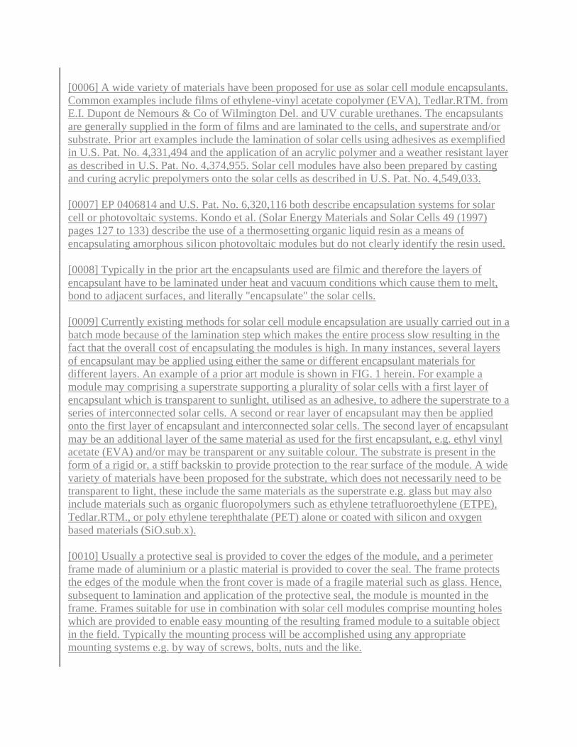
[0009] Currently existing methods for solar cell module encapsulation are usually carried out in a
batch mode because of the lamination step which makes the entire process slow resulting in the
fact that the overall cost of encapsulating the modules is high. In many instances, several layers
of encapsulant may be applied using either the same or different encapsulant materials for
different layers. An example of a prior art module is shown in FIG. 1 herein. For example a
module may comprising a superstrate supporting a plurality of solar cells with a first layer of
encapsulant which is transparent to sunlight, utilised as an adhesive, to adhere the superstrate to a
series of interconnected solar cells. A second or rear layer of encapsulant may then be applied
onto the first layer of encapsulant and interconnected solar cells. The second layer of encapsulant
may be an additional layer of the same material as used for the first encapsulant, e.g. ethyl vinyl
acetate (EVA) and/or may be transparent or any suitable colour. The substrate is present in the
form of a rigid or, a stiff backskin to provide protection to the rear surface of the module. A wide
variety of materials have been proposed for the substrate, which does not necessarily need to be
transparent to light, these include the same materials as the superstrate e.g. glass but may also
include materials such as organic fluoropolymers such as ethylene tetrafluoroethylene (ETPE),
Tedlar.RTM., or poly ethylene terephthalate (PET) alone or coated with silicon and oxygen
based materials (SiO.sub.x).
[0010] Usually a protective seal is provided to cover the edges of the module, and a perimeter
frame made of aluminium or a plastic material is provided to cover the seal. The frame protects
the edges of the module when the front cover is made of a fragile material such as glass. Hence,
subsequent to lamination and application of the protective seal, the module is mounted in the
frame. Frames suitable for use in combination with solar cell modules comprise mounting holes
which are provided to enable easy mounting of the resulting framed module to a suitable object
in the field. Typically the mounting process will be accomplished using any appropriate
mounting systems e.g. by way of screws, bolts, nuts and the like.
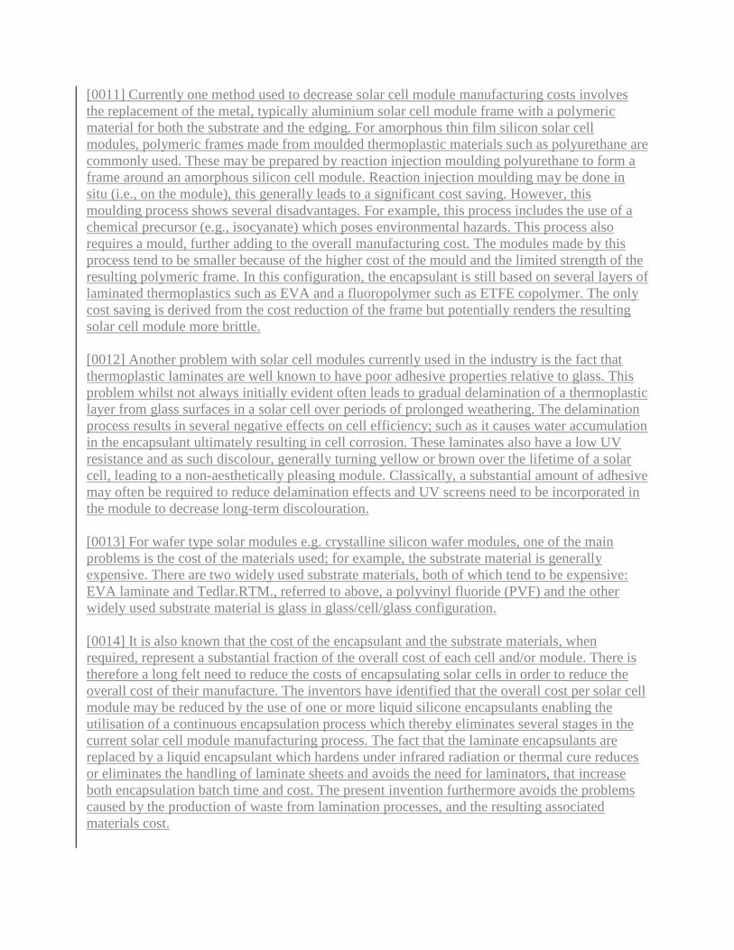
[0011] Currently one method used to decrease solar cell module manufacturing costs involves
the replacement of the metal, typically aluminium solar cell module frame with a polymeric
material for both the substrate and the edging. For amorphous thin film silicon solar cell
modules, polymeric frames made from moulded thermoplastic materials such as polyurethane are
commonly used. These may be prepared by reaction injection moulding polyurethane to form a
frame around an amorphous silicon cell module. Reaction injection moulding may be done in
situ (i.e., on the module), this generally leads to a significant cost saving. However, this
moulding process shows several disadvantages. For example, this process includes the use of a
chemical precursor (e.g., isocyanate) which poses environmental hazards. This process also
requires a mould, further adding to the overall manufacturing cost. The modules made by this
process tend to be smaller because of the higher cost of the mould and the limited strength of the
resulting polymeric frame. In this configuration, the encapsulant is still based on several layers of
laminated thermoplastics such as EVA and a fluoropolymer such as ETFE copolymer. The only
cost saving is derived from the cost reduction of the frame but potentially renders the resulting
solar cell module more brittle.
[0012] Another problem with solar cell modules currently used in the industry is the fact that
thermoplastic laminates are well known to have poor adhesive properties relative to glass. This
problem whilst not always initially evident often leads to gradual delamination of a thermoplastic
layer from glass surfaces in a solar cell over periods of prolonged weathering. The delamination
process results in several negative effects on cell efficiency; such as it causes water accumulation
in the encapsulant ultimately resulting in cell corrosion. These laminates also have a low UV
resistance and as such discolour, generally turning yellow or brown over the lifetime of a solar
cell, leading to a non-aesthetically pleasing module. Classically, a substantial amount of adhesive
may often be required to reduce delamination effects and UV screens need to be incorporated in
the module to decrease long-term discolouration.
[0013] For wafer type solar modules e.g. crystalline silicon wafer modules, one of the main
problems is the cost of the materials used; for example, the substrate material is generally
expensive. There are two widely used substrate materials, both of which tend to be expensive:
EVA laminate and Tedlar.RTM., referred to above, a polyvinyl fluoride (PVF) and the other
widely used substrate material is glass in glass/cell/glass configuration.
[0014] It is also known that the cost of the encapsulant and the substrate materials, when
required, represent a substantial fraction of the overall cost of each cell and/or module. There is
therefore a long felt need to reduce the costs of encapsulating solar cells in order to reduce the
overall cost of their manufacture. The inventors have identified that the overall cost per solar cell
module may be reduced by the use of one or more liquid silicone encapsulants enabling the
utilisation of a continuous encapsulation process which thereby eliminates several stages in the
current solar cell module manufacturing process. The fact that the laminate encapsulants are
replaced by a liquid encapsulant which hardens under infrared radiation or thermal cure reduces
or eliminates the handling of laminate sheets and avoids the need for laminators, that increase
both encapsulation batch time and cost. The present invention furthermore avoids the problems
caused by the production of waste from lamination processes, and the resulting associated
materials cost.

[0015] In accordance with a first aspect of the present invention there is provided a solar cell
module comprising:-- [0016] i) a rigid or flexible superstrate and/or substrate; [0017] ii) one or
more solar cells, and [0018] iii) a cured liquid silicone encapsulant selected from the group of a
hydrosilylation cure reaction product, a peroxide cure reaction product and a UV cure reaction
product.
[0019] In the case where both a superstrate and substrate are present it is preferred that the solar
cells have all their exposed surfaces disposed on either said superstrate or substrate.
[0020] The solar cell may be either a wafer or a thin film based and may be made from any
suitable semi-conductor material such as crystalline or polycrystalline silicon or thin film silicon,
e.g. amorphous, semi crystalline silicon, gallium arsenide, copper indium diselenide, cadmium
telluride,_copper indium gallium diselenide, mixtures including any one or more of the latter and
the like. In the case of wafer based solar cells, preferably the wafer is polycrystalline or
crystalline silicon. In the case of thin film solar cells, the thin film is preferably made from
amorphous silicon (aSi), cadmium telluride or copper indium gallium diselenide. The solar cell
may be any suitable type solar cell including simple wafer and thin layer solar cells but also
split-spectrum cells and the like. The module may be any suitable type of solar cell module
including concentrators etc.
[0021] Preferably, in respect of wafer based solar cell modules in accordance with the present
invention the rigid or flexible superstrate and/or substrate comprise a rigid superstrate which is
transparent to light.
[0022] Preferably, in the case of thin film solar cell modules, the rigid or flexible superstrate
and/or substrate comprises a rigid or flexible substrate, such as for example glass or a flexible
metal sheet.
[0023] The liquid silicone encapsulant in accordance with the invention preferably comprises:
[0024] Component (A) 100 parts by weight of a liquid diorganopolysiloxane having at least two
Si-alkenyl groups per molecule and a viscosity at 25.degree. C. of from 100 to 15,000 nPas;
[0025] Component (B) 20 to 50 parts by weight of a silicone resin containing at least two alkenyl
groups; [0026] Component (C) a cross-linking agent in the form of a polyorganosiloxane having
at least two silicon-bonded hydrogen atoms per molecule, in an amount such that the ratio of the
number of moles of silicon-bonded hydrogen to the total number of moles of silicon-bonded
alkenyl groups is from 0.1:1 to 5:1; [0027] Component (D) a hydrosilylation catalyst selected
from platinum, rhodium, iridium, palladium or ruthenium based catalysts, but which is preferably
a platinum based catalyst wherein the amount of platinum metal in said platinum-based catalyst
is from 0.01 to 500 parts by weight per 1,000,000 parts by weight of component (A).
[0028] The proportions of components (A), (B), (C) and (D) may comprise any suitable amounts.
The final viscosity of the resulting uncured composition may be, but is not essentially, able to
self-level within a short period of time after having been dispensed. The preferred viscosity of
the final composition is preferably from 100 to 10 000 mPas measured at 25.degree. C., more
preferably from 100 to 5000 mPas

[0029] Component (A) is preferably a liquid diorganopolysiloxane, represented by the following
average unit formula: R.sub.aSiO.sub.(4-a)/2 Wherein each R is the same or different and is a
monovalent hydrocarbon group, for example a linear or branched alkyl group such as methyl,
ethyl, propyl, isopropyl t-butyl, and pentyl; an alkenyl group such as vinyl, allyl, or hexenyl; and
an aryl group such as phenyl. "a" is a number with an average value between 1.8 and 2.3.
Preferably, component (A) has a viscosity at 25.degree. C. of from 100 to 10,000 mPas, a
molecular structure which is substantially linear although may be partially branched and a
relatively low molecular weight of from 10000 to 50000, more preferably from 15000 to 30000.
Preferably, component (A) comprises alkenyl terminal groups.
[0030] Examples of component (A) include
a dimethylvinylsiloxy-terminated dimethylpolysiloxane,
a dimethylvinylsiloxy-terminated copolymer of methylvinylsiloxane and dimethylsiloxane,
a dimethylvinylsiloxy-terminated copolymer of methylphenylsiloxane and dimethylsiloxane,
a dimethylvinylsiloxy-terminated copolymer of methylphenylsiloxane, methylvinylsiloxane, and
dimethylsiloxane,
a dimethylvinylsiloxy-terminated copolymer of diphenylsiloxane and dimethylsiloxane,
a dimethylvinylsiloxy-terminated copolymer of diphenylsiloxane, methylvinylsiloxane, and
dimethylsiloxane, or any suitable combination of the above
[0031] Component (3) is a Silicone resin containing at least two alkenyl groups comprising
SiO.sub.4/2 units (also known as Q units) and units selected from R'SiO.sub.3/2 (also known as
T units), R'.sub.2SiO.sub.2/2, and R'.sub.3SiO.sub.1/2 units, where each R' may be the same or
different and is R or a hydrogen atom. It is preferred to disperse component (B) in a suitable
amount of component (A) or a solvent to ensure ease of mixing with bulk of component (A).
Any suitable solvents may be used such as for example aromatic solvents such as toluene and
xylene, ketones such as methyl isobutyl ketone, alcohols such as isopropanol and non-aromatic
cyclic solvents such as hexane. Typically, when a solvent is used, xylene is preferred.
[0032] Component (C) is a cross-linking agent in the form of a polyorganosiloxane having at
least two silicon-bonded hydrogen atoms per molecule and has the following average unit
formula: R.sup.i.sub.bSiO.sub.(4-b)/2 where each R.sup.1 may be the same or different and is
hydrogen, an alkyl group such as methyl, ethyl, propyl, and isopropyl or an aryl group such as
phenyl and tolyl. Component (C) may have a linear, partially branched linear, cyclic, or a net-
like structure.
[0033] Examples of the aforementioned organopolysiloxane include one or more of the
following:--
a trimethylsiloxy-terminated polymethylhydrogensiloxane,

a trimethylsiloxy-terminated copolymer of methylhydrogensiloxane and dimethylsiloxane,
a dimethylhydrogensiloxy-terminated copolymer of methylhydrogensiloxane and
dimethylsiloxane,
a cyclic copolymer of methylhydrogensiloxane and dimethylsiloxane,
an organopolysiloxane composed of siloxane units expressed by the formula
(CH.sub.3).sub.3SiO.sub.1/2, siloxane units expressed by the formula
(CH.sub.3).sub.2HSiO.sub.1/2, and siloxane units expressed by the formula SiO.sub.4/2,
an organopolysiloxane composed of siloxane units expressed by the formula
(CH.sub.3).sub.2HSiO.sub.1/2, siloxane units expressed by the formula CH.sub.3SiO.sub.3/2,
an organopolysiloxane composed of siloxane units expressed by the formula
(CH.sub.3).sub.2HSiO.sub.1/2, siloxane units expressed by the formula
(CH.sub.3).sub.2SiO.sub.1/2, and siloxane units expressed by the formula CH.sub.3SiO.sub.3/2,
a dimethylhydrogensiloxy-terminated polydimethylsiloxane,
a dimethylhydrogensiloxy-terminated copolymer of methylphenylsiloxane and dimethylsiloxane,
and
a dimethylhydrogensiloxy-terminated copolymer of a methyl (3,3,3-trifluoropropyl) siloxane and
dimethylsiloxane.
[0034] Preferably, the viscosity of the cross-linking agent (C) at 25.degree. C. is in a range of
from 2 to 100,000 mPas. It is recommended that component (C) be added in an amount such that
the mole ratio of silicon-bonded hydrogen atoms in the cross-linking agent (C) to the mole
number of alkenyl groups in component (A) is in the range of from 0.1:1 to 5:1, more preferably
it is in the range of from 0.8:1 to 4:1. If the above ratio is lower than 0.1:1, the density of cross-
linking will be too low and it will be difficult to obtain a rubber-like elastomer. A ratio having an
excess of Si--H groups (i.e. >1:1) is preferred to enhance adhesion between the
superstrate/substrate e.g. glass and the encapsulant.
[0035] Component (D) is a hydrosilylation (addition cure) catalyst may comprise any suitable
platinum, rhodium, iridium, palladium or ruthenium based catalyst. However preferably
component (D) is a platinum based catalyst. The platinum-based catalyst may be any suitable
platinum catalyst such as for example a fine platinum powder, platinum black, chloroplatinic
acid, an alcoholic solution of chloroplatinic acid, an olefin complex of chloroplatinic acid, a
complex of chloroplatinic acid and alkenylsiloxane, or a thermoplastic resin that contain the
aforementioned platinum catalyst. The platinum catalyst is used in an amount such that the
content of metallic platinum atoms constitutes from 0.1 to 500 parts by weight per 1,000,000
parts by weight of component (A). A hydrosilylation or addition cure reaction is the reaction
between an Si--H group (typically provided as a cross-linker) and an Si-alkenyl group, typically

a vinyl group, to form an alkylene group between adjacent silicon atoms (.dbd.Si--CH.sub.2--
CH.sub.2--Si.dbd.).
[0036] The composition may also comprise one or more curing inhibitors in order to improve
handling conditions and storage properties of the composition, for example acetylene-type
compounds, such as 2-methyl-3-butyn-2-ol, 2-phenyl-3-butyn-2-ol, 3,5-dimethyl-1-hexyn-3-ol,
1-ethynyl-1-cyclohexanol, 1,5-hexadiene, 1,6-heptadiene; 3,5-dimethyl-1-hexen-1-yne; 3-ethyl-
3-buten-1-yne and/or 3-phenyl-3-buten-1-yne; an alkenylsiloxane oligomer such as 1,3-
divinyltetramethyldisiloxane, 1,3,5,7-tetravinyltetramethyl cyclotetrasiloxane, or 1,3-divinyl-1,3-
diphenyldimethyldisiloxane; a silicon compound containing an ethynyl group such as methyltris
(3-methyl-1-butyn-3-oxy) silane; a nitrogen-containing compound such as tributylamine,
tetramethylethylenediamine, benzotriazole; a similar phosphorus-containing compound such as
triphenylphosphine; as well as sulphur-containing compounds, hydroperoxy compounds, or
maleic-acid derivatives.
[0037] The aforementioned curing inhibitors are used in an amount of from 0 to 3 parts by
weight, normally from 0.001 to 3 parts by weight, and preferably from 0.01 to 1 part by weight
per 100 parts by weight of component (A). Most preferable among the curing inhibitors are the
aforementioned acetylene-type compounds, which demonstrate the best balance between storage
characteristics and speed of curing when they are used in a combination with aforementioned
component (D).
[0038] Where required one or more adhesion promoters may also be used to enhance the
adhesion of the encapsulant to a superstrate and/or substrate surface. Any suitable adhesion
promoter may be utilised. Examples include
vinyltriethoxysilane,
acrylopropyltrimethoxysilane,
alkylacrylopropyltrimethoxysilane
Allyltriethoxysilane,
glycidopropyltrimethoxysilane,
allylglycidylether
hydroxydialkyl silyl terminated methylvinylsiloxane-dimethylsiloxane copolymer, reaction
product of hydroxydialkyl silyl terminated methylvinylsiloxane-dimethylsiloxane copolymer
with glycidopropyltrimethoxysilane; and,
bis-triethoxysilyl ethylene glycol (reaction product of triethoxysilane with ethylene glycol).
[0039] Preferred adhesion promoters are [0040] i) hydroxydialkyl silyl terminated
methylvinylsiloxane-dimethylsiloxane copolymer, [0041] ii) reaction product of hydroxydialkyl

silyl terminated methylvinylsiloxane-dimethylsiloxane copolymer with
glycidopropyltrimethoxysilane; and [0042] iii) bis-triethoxysilyl ethylene glycol [0043] iv) a
0.5:1 to 1:2, preferably about 1:1, mixture of (i) and a methacrylopropyltrimethoxysilane
[0044] Anti-soiling additives may be utilised, where required to prevent soiling when the solar
cells are in use, particularly preferred are fluoroalkene or a fluorosilicone additives that has a
viscosity of 10000 mPas such as:--fluorinated silsesquixoanes, e.g. dimethylhydrogensiloxy
terminated trifluoropropyl silsesquioxane, hydroxy-terminated trifluoropropylmethyl siloxane,
hydroxy-terminated trifluoropropylmethylsilyl methylvinylsilyl siloxane,
3,3,4,4,5,5,6,6,7,7,8,8,8-Tridecafluorooctyltriethoxysilane, hydroxy-terminated methylvinyl,
trifluoropropylsilaxane, and dimethylhydrogensiloxy-terminated dimethyl trifluoropropylmethyl
siloxane
[0045] Preferably, the anti-soiling additive is present in an amount of from 0 to 5 parts by
weight, more preferably 0 to 2 parts by weight and most preferably 0 to 1.5 parts by weight.
Preferably when the encapsulant is used both in the absence of the adhesive layer referred to
below the anti-soiling additive is included in the encapsulant composition as well as when used
in combination with the adhesive layer.
[0046] Other additives that enhance the physical properties may be utilised in the composition.
One particular example is the inclusion of a fire retardant. Any suitable fire retardant or mixture
of fire retardants may be used providing they do not negatively affecting the other physical
properties of the encapsulant composition. Examples include alumina powder, or wollastonite as
described in WO 00/46817. The latter may be used alone or in combination with other fire
retardants or a pigment such as titanium dioxide. In cases where the encapsulant need not be
transparent to light, it may comprise a pigment.
[0047] In one aspect of the present invention the solar cell module comprises thin film solar
cells. Preferably, a solar cell module comprising thin film solar cells requires a single layer of
encapsulant. In the case where a single layer of encapsulant is utilised the silicone encapsulant is
designed to be hard and scratch resistant and thereby is designed to function as both an
adhesive/top coat and avoids the need for an expensive substrate of the type generally utilised in
the prior art. Preferably, solar cell modules comprising a single layer of encapsulant incorporate
the aforementioned anti-soiling additive.
[0048] In the case when a single layer of encapsulant is utilised it is preferred that component
(C) of the formulation has an excess of Si--H groups, i.e. the ratio of the number of moles of
silicon-bonded hydrogen to the total number of moles of silicon-bonded alkenyl groups is
preferably 0.8:1 to 5:1, more preferably >1:1 and most preferably from 1:1 to 4:1.
[0049] Hence in the case of a solar cell module with a single layer of encapsulant in accordance
with the present invention, Component (A) preferably is a high molecular weight polymer,
component (B) is present in an amount of from 30 to 50 parts by weight of a silicone resin
containing at least two alkenyl groups and Component (C) is a cross-linking agent in the form of
a polyorganosiloxane having at least two silicon-bonded hydrogen atoms per molecule, in an
amount such that the ratio of the number of moles of silicon-bonded hydrogen to the total

number of moles of silicon-bonded alkenyl groups in component is from 0.8:1 to 5:1 and more
preferably from 1:1 to 4:1. Furthermore, the composition comprises an anti-soiling additive.
[0050] Any suitable process may be used to prepare the uncured liquid silicone encapsulant; for
example, component (13) may be premixed with component (A) and component (C) and then co-
cross-linked in the presence of a low level of platinum catalyst to form a tough polymer network.
A small amount of a catalyst inhibitor such as ethylhexynol may be added to prolong the bath
time of the encapsulant. When heated above 90.degree. C., the mixture initially forms a non-
transparent two-phase system due to the presence of the anti-soiling additive and then becomes
highly transparent. To ensure the long lasting bonding of the encapsulant to all adjacent surfaces,
a small amount of adhesion promoter is preferably use. It is believed that the adhesion promoter
migrates to the interface of the topcoat and reacts irreversibly with adjacent surfaces. This strong
adhesion allows the module to function in wide range of temperatures from ambient temperature
to extremes without delaminating.
[0051] The single layer encapsulant is designed to have a required abrasion resistance to prevent
further damage that may occur during transportation or in field usage. It is tough enough to serve
also as the substrate protecting the cell.
[0052] The combination of encapsulant and topcoat is designed to replace multiple layers and
material chemistry of the classical configuration (EVA and fluoropolymer laminate) by two
layers based on one core chemistry. The topcoat preferably covers the entire cell interconnects; it
functions as an outer layer i.e. as an environmentally protecting layer.
[0053] Component (B) of the composition as hereinbefore described is provided because silicone
resins of this type impart outstanding UV resistance to the encapsulant and therefore there is no
need for the inclusion of one or more UV screen additives which in the case of most prior art
formulations was typically essential. The cured liquid silicone encapsulant of the type described
in the present invention exhibits long term UV & visual light transmission thereby allowing the
maximum amount of light to reach solar cells.
[0054] Whilst the UV resistance capabilities of silicone based compositions is well known the
commercial exploitation of such formulations have been limited by high total cost and a lack of
suitable process to dispense a liquid encapsulation.
[0055] In the case of thin film solar cell modules the inventors have found that the encapsulant as
hereinbefore described is adequate to replace the often several layers of encapsulant and avoids
the need for a substrate. The encapsulant is located between e.g. a glass plate superstrate and the
solar cell and its primary function is to protect the solar cell against mechanical stress arising
from temperature changes, and to adhere the solar cell to the superstrate.
[0056] However, particularly in the case of wafer type solar cell modules it has been identified
that in some instances an optional adhesive layer comprising a further liquid silicone encapsulant
may be utilised for the adhesion of the wafer type solar cells onto the load bearing support,
typically a superstrate.

[0057] The liquid silicone encapsulant utilised as the intermediate adhesive layer (henceforth
referred to as the adhesive) is preferably substantially the same basic formulation as the single
layer encapsulant described to above and preferably comprises: [0058] Component (Ai) 100
parts by weight of a liquid diorganopolysiloxane having at least two Si-alkenyl groups per
molecule and a viscosity at 25.degree. C. of from 100 to 10,000 mPas; [0059] Component (Bi)
20 to 40 parts by weight of a silicone resin containing at least two alkenyl groups; [0060]
Component (Ci) a cross-linking agent in the form of a polyorganosiloxane having at least two
silicon-bonded hydrogen atoms per molecule, in an amount such that the ratio of the number of
moles of silicon-bonded hydrogen to the total number of moles of silicon-bonded alkenyl groups
is from 0.1:1 to 1:1; [0061] Component (Di) a hydrosilylation catalyst selected from platinum,
rhodium, iridium, palladium or ruthenium based catalysts, but which is preferably a platinum
based catalyst wherein the amount of platinum metal in said platinum-based catalyst is from 0.01
to 500 parts by weight per 1,000,000 parts by weight of component (Ai).
[0062] The proportions of components (Ai), (Bi), (Ci) and (Di) may comprise any suitable
amounts. The final viscosity of the resulting uncured composition may be, but is not essentially,
able to self-level within a short period of time after having been dispensed. The preferred
viscosity of the final composition is preferably from 100 to 2000 mPas measured at 25.degree.
C., more preferably from 500 to 1000 mPas.
[0063] Preferably, the viscosity of component (Ai) of the adhesive is lower than the viscosity of
component (A) of the aforementioned encapsulant. Preferably when both encapsulant and
adhesive are utilised, the encapsulant comprises a resin fraction of between 20% to 90% by
weight, preferably between 25% to 70% and more preferably between 30-60% and the adhesive
comprises a resin fraction of from 20-30% by weight.
[0064] The adhesive may also comprise any one or more of the optional additives described with
respect to the encapsulant formulation. Preferably the adhesive layer comprises a suitable
adhesion promoter, most preferably one of the adhesion promoters listed above with respect to
the encapsulant composition.
[0065] The adhesive composition may be cured by any suitable process, for example component
(Bi) may be premixed with components (Ai) and (Ci) and then co-cross-linked in the presence of
platinum catalyst to form a tough network. Preferably, a small amount of a catalyst inhibitor,
such as for example ethylhexynol, is added to allow a prolonged bath time of the material. To
ensure a long lasting bonding interaction between the encapsulant and all adjacent surfaces, a
small amount of adhesion promoter, typically an alkoxysilane, is added and the ratio of Si--H
bonds to Si-alkenyl bonds is lower than 1:1, such as for example 0.6:1. It is believed that the
adhesion promoter migrates to the interface of the encapsulant and reacts irreversibly with
adjacent surfaces. This strong adhesion allows the module to function over a wide range of
temperatures without or substantially without delaminating. The excess of alkenyl groups also
helps the bonding/adhesion of the intermediate layer of adhesive with the encapsulant which is in
this case functioning as a topcoat.
[0066] Both the encapsulant and, where utilized, the adhesive provide homogeneous and
transparent silicone films that maintains a high flexibility due to the presence of the linear or
substantially linear polymers of component (A). The encapsulant, when cured, has a higher tear
resistance than the adhesive. The anti-soiling additives are added to the encapsulant, to increase
the soil resistance of the material and are used in amounts which will not noticeably negatively
affect the abrasion resistance properties thereof. In a composition such as that of the encapsulant
of the present invention, the anti-soiling additives are believed to migrate and spread rapidly at
the silicone/air interface making a low surface energy surface but remain chemically bonded to
the silicone matrix. The soil accumulation on the outwardly facing side (at the interface with the
environment) of the encapsulant is inversely proportional to the surface energy, which is related
to the level of anti-soiling additives on the surface.
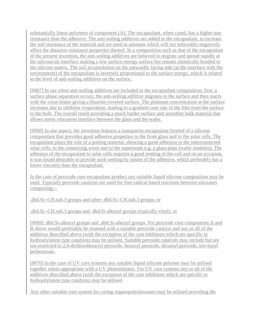
[0067] In use when anti-soiling additives are included in the encapsulant composition; first, a
surface phase separation occurs; the anti-soiling additive migrates to the surface and then reacts
with the cross-linker giving a fluorine-covered surface. The platinum concentration at the surface
increases due to inhibitor evaporation, leading to a gradient cure rate of the film from the surface
to the bulk. The overall result providing a much harder surface and smoother bulk material that
allows stress relaxation interface between the glass and the wafer.
[0068] In one aspect, the invention features a transparent encapsulant formed of a silicone
composition that provides good adhesive properties to the front glass and to the solar cells. The
encapsulant plays the role of a potting material, showing a good adhesion to the interconnected
solar cells, to the connecting wires and to the superstrate e.g. a glass plate (wafer modules). The
adhesion of the encapsulant to solar cells requires a good wetting of the cell and on an occasion,
it was found desirable to provide such wetting by means of the adhesive, which preferably has a
lower viscosity than the encapsulant.
In the case of peroxide cure encapsulant product any suitable liquid silicone composition may be
used. Typically peroxide catalysts are used for free-radical based reactions between siloxanes
comprising:--
.dbd.Si--CH.sub.3 groups and other .dbd.Si--CH.sub.3 groups; or
.dbd.Si--CH.sub.3 groups and .dbd.Si-alkenyl groups (typically vinyl); or
[0069] .dbd.Si-alkenyl groups and .dbd.Si-alkenyl groups. For peroxide cure components A and
B above would preferably be retained with a suitable peroxide catalyst and any or all of the
additives described above (with the exception of the cure inhibitors which are specific to
hydrosilylation type catalysis) may be utilised. Suitable peroxide catalysts may include but are
not restricted to 2,4-dichlorobenzoyl peroxide, benzoyl peroxide, dicumyl peroxide, tert-butyl
perbenzoate.
[0070] In the case of UV cure systems any suitable liquid silicone polymer may be utilised
together where appropriate with a UV photoinitiator. For UV cure systems any or all of the
additives described above (with the exception of the cure inhibitors which are specific to
hydrosilylation type catalysis) may be utilised
Any other suitable cure system for curing organopolysiloxanes may be utilised providing the

uncured organopolysiloxane composition used is suitable for application in accordance with any
one of the processes described below.
[0071] The inventors have also found a new way of passivating the surface of a solar cell and/or
photovoltaic cell which may be encapsulated by any system i.e. using the composition as
described in the present invention or the prior art processes and lamination techniques. The
coating of the cell surface with a trialkoxysilane results in a primer or passivating layer which
has good adhesion to the cell surface and typically to the encapsulant used. It will passivate the
surface and thereby increase the wetting of the cell(s) in order to reduce or avoid problems with
bubble formation between the cell and the encapsulant and/or adhesive. It will also protect the
cell after encapsulation from water ingress and corrosion. The chosen silane may be applied as a
precoating onto the solar cell(s) or may be added in a suitable concentration in the encapsulant
composition. The pre-coating may comprise the silane alone or a solution of the silane in a
solvent such as an alcohol, the latter of which is allowed to evaporate after application.
Typically, the layer of the passivation coating might be as small as 2 .mu.m thick. Most
preferably the passivation layer is provided on wafer type solar cells. Preferably the silane has
the formula:--(R.sup.1O).sub.3SiR.sup.2 wherein R.sup.1 is an alkyl group comprising 1 to 6
carbon atoms, R.sup.2 is selected from the group of an alkoxy group comprising 1 to 6 carbon
atoms, an alkyl group comprising 1 to 6 carbon atoms an alkenyl group comprising 1 to 6 carbon
atoms, an acrylic group or an alkyl acrylic group. Preferably, the trialkoxysilane is for example, a
trimethoxysilane or triethoxysilane, most preferably methacrylopropyltrimethoxysilane.
[0072] Advantages of the solar modules encapsulated using the liquid silicone encapsulant
described above include:-- [0073] i) A reduction of the Total cost-in-use of modules i.e. a
reduction in the total cost taking all the parameters including material, application process,
quantity of material per square meter); [0074] ii) Module Durability--modules made using the
compositions described in the present invention are both enhance efficiency of manufacture and
reduce problems of discoloration after ageing due to UV exposure. [0075] iii) Due to the
physical properties of the liquid silicone encapsulant fire resistant properties are significantly
improved over prior art modules. [0076] iv) The application of the encapsulant and, where used,
the adhesive by any chosen method using the compositions described in the present invention,
e.g. curtain coating is undertaken at room temperature (although some heating may be utilised).
[0077] In another aspect of the present invention there is provided a continuous method of
encapsulating solar cell modules using the liquid silicone encapsulant material described above.
[0078] The current standard industry process generally utilizes an EVA (ethyl vinyl acetate)
thermoplastic encapsulant and a laminatable backing material such polyester/Tedlar.RTM. and
the cell or array of cells/module is prepared using a lamination technique. Typically, a suitable
laminator is used to laminate the following "sandwich" of layers. [0079] 1) Glass superstrate,
[0080] 2) EVA, [0081] 3) solar cell series, [0082] 4) EVA, and [0083] 5) Substrate in the form of
a suitable backing material
[0084] The standard process uses the laminator apparatus to melt the layers of the "sandwich" at
a temperature in the region of 140.degree. C. (actual temperature used is determined in view of
the actual composition being laminated) under vacuum for about 20 minutes per module. After
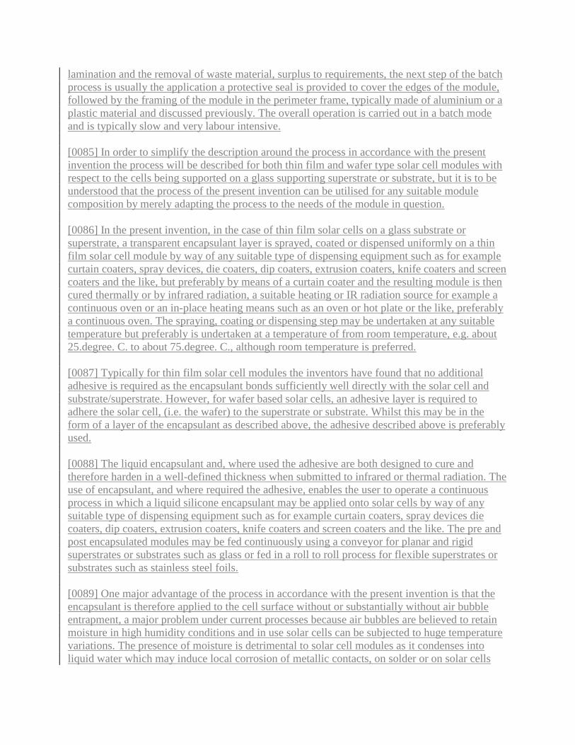
lamination and the removal of waste material, surplus to requirements, the next step of the batch
process is usually the application a protective seal is provided to cover the edges of the module,
followed by the framing of the module in the perimeter frame, typically made of aluminium or a
plastic material and discussed previously. The overall operation is carried out in a batch mode
and is typically slow and very labour intensive.
[0085] In order to simplify the description around the process in accordance with the present
invention the process will be described for both thin film and wafer type solar cell modules with
respect to the cells being supported on a glass supporting superstrate or substrate, but it is to be
understood that the process of the present invention can be utilised for any suitable module
composition by merely adapting the process to the needs of the module in question.
[0086] In the present invention, in the case of thin film solar cells on a glass substrate or
superstrate, a transparent encapsulant layer is sprayed, coated or dispensed uniformly on a thin
film solar cell module by way of any suitable type of dispensing equipment such as for example
curtain coaters, spray devices, die coaters, dip coaters, extrusion coaters, knife coaters and screen
coaters and the like, but preferably by means of a curtain coater and the resulting module is then
cured thermally or by infrared radiation, a suitable heating or IR radiation source for example a
continuous oven or an in-place heating means such as an oven or hot plate or the like, preferably
a continuous oven. The spraying, coating or dispensing step may be undertaken at any suitable
temperature but preferably is undertaken at a temperature of from room temperature, e.g. about
25.degree. C. to about 75.degree. C., although room temperature is preferred.
[0087] Typically for thin film solar cell modules the inventors have found that no additional
adhesive is required as the encapsulant bonds sufficiently well directly with the solar cell and
substrate/superstrate. However, for wafer based solar cells, an adhesive layer is required to
adhere the solar cell, (i.e. the wafer) to the superstrate or substrate. Whilst this may be in the
form of a layer of the encapsulant as described above, the adhesive described above is preferably
used.
[0088] The liquid encapsulant and, where used the adhesive are both designed to cure and
therefore harden in a well-defined thickness when submitted to infrared or thermal radiation. The
use of encapsulant, and where required the adhesive, enables the user to operate a continuous
process in which a liquid silicone encapsulant may be applied onto solar cells by way of any
suitable type of dispensing equipment such as for example curtain coaters, spray devices die
coaters, dip coaters, extrusion coaters, knife coaters and screen coaters and the like. The pre and
post encapsulated modules may be fed continuously using a conveyor for planar and rigid
superstrates or substrates such as glass or fed in a roll to roll process for flexible superstrates or
substrates such as stainless steel foils.
[0089] One major advantage of the process in accordance with the present invention is that the
encapsulant is therefore applied to the cell surface without or substantially without air bubble
entrapment, a major problem under current processes because air bubbles are believed to retain
moisture in high humidity conditions and in use solar cells can be subjected to huge temperature
variations. The presence of moisture is detrimental to solar cell modules as it condenses into
liquid water which may induce local corrosion of metallic contacts, on solder or on solar cells

and furthermore may cause early delamination of the modules.
[0090] In the case of interconnecting wafer type solar cells, the adhesive as hereinbefore
described is preferably sprayed, coated or dispensed uniformly onto the back of a superstrate or
substrate, e.g. a glass plate by means of curtain coaters, spray devices, die coaters, dip coaters,
extrusion coaters, knife coaters and screen coaters and the like, preferably a curtain coater. Then
the interconnected solar cells are deposited onto/in to the uncured adhesive. The adhesive is then
cured/hardened thermally or by infrared radiation in such a way that the adhesive fixes the
interconnected solar cells in a predefined position on the superstrate/substrate, by a suitable
heating or IR radiation source for example a continuous oven or an in-place heating means such
as an oven or hot plate or the like. Then an amount of encapsulant as described hereinbefore is
uniformly applied to totally encapsulate the whole module by means of curtain coaters, spray
devices, die coaters, dip coaters, extrusion coaters, knife coaters and screen coaters and the like,
preferably a curtain coater and the resulting module is then cured/hardened thermally or by
infrared radiation using a suitable heating or IR radiation source for example a continuous oven
or an in-place heating, preferably a continuous oven.
[0091] Alternatively for wafer based solar cell systems a sufficient amount of encapsulant or if
used adhesive is sprayed, coated or dispensed uniformly onto a glass superstrate/substrate and
then the interconnecting solar cells are carefully immersed into a further amount of the same
material and subsequently the resulting module is cured and hardened either thermally or by
infrared radiation and where required a top-coat of encapsulant is sprayed, coated or dispensed
(as described above) uniformly onto the cured adhesive and subsequently is cured and hardened
either thermally or by infrared radiation as described above.
[0092] In one aspect of the present invention, the frame or edge sealing material may be applied
to the substrate/superstrate before encapsulation and not after completion of the encapsulation
process via the laminating processes of the prior art. This forms a guide for where the
encapsulant and/or adhesive needs to be applied in liquid form.
[0093] Preferably the application of both encapsulant and adhesive may be carried out at about
room temperature but some heating may be utilised up to e.g. a temperature of 75.degree. C.,
preferably no greater than 50.degree. C. in order to reduce the viscosity of the encapsulant or
adhesive being applied on to the module.
[0094] Preferably, the electrical leads in a module are treated using either of the above suggested
methods are protected against coating with encapsulant and/or if used adhesive. The protected
leads may be further bonded into an electrical junction box on the substrate or back skin material
to form an integral seal. The liquid silicone coatings may be sealed and inserted into a metal,
thermoplastic or elastomeric frame which also provide additional protection against water
ingress at the edge of the panel. However, it was identified that with a silicone encapsulant in
accordance with the present invention such a frame was not necessarily required unlike for solar
cell modules prepared by the prior art lamination type processes.
[0095] One very important aspect when compared to prior art lamination based processes is that
the entire process in accordance with this aspect of the invention may be automated into an

integrated assembly line with process control and as such is a significantly less labour intensive.
[0096] In a preferred embodiment of the process in accordance with the present invention there
is provided a continuous process using one or more means of coating the encapsulant and
adhesive (where used) such as curtain coaters, spray devices and die coaters dip coaters,
extrusion coaters, knife coaters and screen coaters and the like, although curtain coaters are
preferred followed by an appropriate curing step, typically using a thermal or IR oven.
[0097] This process may be used for both organic and silicone systems provided the viscosity of
the coatings involved are suitable for use in combination with the means of applying the coating
such as a curtain coater, although the process is preferably used in combination with encapsulant
and adhesive formulation of the type described herein. Hence, preferably the viscosity of the
uncured composition is no greater than 50000 mPas and most preferably no greater than 40000
mPas.
[0098] The preferred means of applying encapsulant and where required adhesive is by means of
a curtain coater. Curtain coating is a process for applying a thin layer of liquid onto a solid
material. Curtain coating machines are adapted to disperse liquid at a controlled rate over the
width of its coating head onto a target (in the case of this application solar cell modules). The
resulting wide, thin flow of liquid resembles a "curtain" hence the name "Curtain Coater." By
passing the target (the solar cell modules) under the curtain of liquid at a predefined constant
speed an even layer of liquid is deposited on the target (the solar cell modules). The ability of the
user to control both the flow rate of the liquid and the speed of the target through the curtain of
liquid a very accurate thickness of the coat is obtained.
[0099] Encapsulant or adhesive is initially retained in a reservoir tank, and when required is
pumped from the tank, through a filter to coating head. The coating head may be either
pressurised or non-pressurised depending on the viscosity of the coating being used (but in the
present invention will usually be pressurized due to the viscosity of the encapsulant and adhesive
when used. The encapsulant or adhesive flows through a dye in the coating head to form a
`curtain` of liquid under the effects of gravity. The Solar cell module to be coated is transferred
along an in-feed conveyor, through the curtain of material, and onto an out-feed conveyor.
Preferably the `curtain` of encapsulant or adhesive is wider than the solar cell modules being
coated so that all excess material falls through a gap between the in-feed and out-feed conveyors
into a collection trough, and flows back to the feed tank, thereby avoiding any unnecessary
waste.
[0100] The feed tank is typically deep and constructed with baffles, so that the encapsulant or
adhesive must follow a "tortuous" path, thus allowing time for any entrained air to escape before
getting to the pump suction.
[0101] A curtain coater is generally used for processes involving much less viscous liquids and it
was imperative for the process of the present invention that the curtain coater used did not cause
frothing and or bubbling. Several adjustments were required in the stock equipment to handle
liquids of the viscosities of the encapsulant and adhesive described in the present invention.
These were mainly directed to reducing the amount entrained air in the system to minimise the

likelihood of the encapsulant and adhesive where used to foam or retain air bubbles. The curtain
coater was preferably fitted with high powered pumps as the standard diaphragm pumps cannot
be used since they introduce air into the system and would not be practical for application of the
liquid encapsulant which may have a relatively high viscosity for a liquid of up to e.g. 10.000
mPas.
[0102] Preferably, the curtain coater has a centre feed system. This is because whilst lower
viscosity liquid can be fed from any position on the coater head, but as the viscosity of the
liquids utilised is higher than normally expected for use with this type of coater resulting in the
need for longer times than normal being required for levelling the encapsulant and/or adhesive in
the modules.
[0103] Preferably, the curtain coater feeder head utilises surface feed to avoid the entrainment of
air. This is because whilst lower viscosity liquids of the type typically applied by curtain coaters
are fed in any submerged depth position (z dimension) from the bottom to the top of the coater
head tank, normally it is fed in a submerged manner to control splashing.
[0104] Preferably, the curtain coater has an anti-splash "pan" at the bottom of the curtain fall.
This is provided in the form of a rolled metal pan which is provided to contribute to the laminar
flow into the discharge and help prevent entrained air.
[0105] Preferably the Feed tanks are preferably both larger (overall capacity) and taller than
normal feed tanks used for standard curtain coaters, to allow entrained air bubbles to rise to the
surface of the tank according to Stokes law, and again help reduce the entrained air.
[0106] Preferably the normal operating speed of the curtain coater may be lowered as compared
to prior art curtain coaters. This is preferable because the lower operating speed range of the
coater conveying system in order to allow better speed control of the speed of feeding the glass
superstrates and/or substrates through the curtain coater, thereby providing better control curtain
thickness.
[0107] Preferably, the curtain coater comprises a plurality of several curtain guides to the coater
head to control the width of the curtain and/or allow the use of a multiple series of curtains. This
provided coating flexibility and permitted the use of the same coating equipment for the coating
of many different sizes of solar modules and arrays and the like.
[0108] Preferably, the curtain coater comprises a long return pipe and coalescer to remove gross
bubbles from the system.
[0109] The curtain coater may also optionally comprise a heating system to heat the liquid as it
approaches the curtain. Heating the encapsulant and adhesive when used to about 50.degree. C.,
has the advantage of reducing the viscosity and enhances the probability of any microscopic
bubbles present in the composition to be applied to rise to the surface.
[0110] Preferably the encapsulant and where used adhesive is de-aired prior to coating. Any
suitable de-airing process may be utilised, e.g. by vacuum but preferably the curtain coater is
provided with a semi-continuous vacuum stripper to de-air liquid before feeding it into or back
into the coater head.
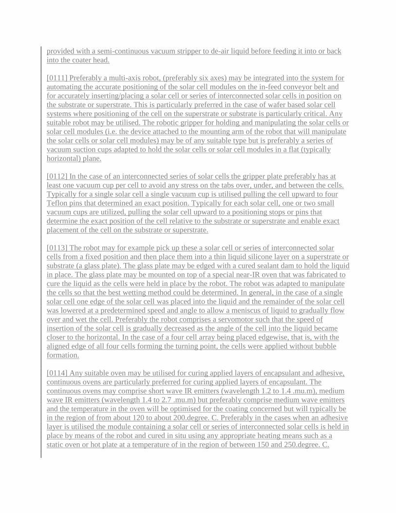
[0111] Preferably a multi-axis robot, (preferably six axes) may be integrated into the system for
automating the accurate positioning of the solar cell modules on the in-feed conveyor belt and
for accurately inserting/placing a solar cell or series of interconnected solar cells in position on
the substrate or superstrate. This is particularly preferred in the case of wafer based solar cell
systems where positioning of the cell on the superstrate or substrate is particularly critical. Any
suitable robot may be utilised. The robotic gripper for holding and manipulating the solar cells or
solar cell modules (i.e. the device attached to the mounting arm of the robot that will manipulate
the solar cells or solar cell modules) may be of any suitable type but is preferably a series of
vacuum suction cups adapted to hold the solar cells or solar cell modules in a flat (typically
horizontal) plane.
[0112] In the case of an interconnected series of solar cells the gripper plate preferably has at
least one vacuum cup per cell to avoid any stress on the tabs over, under, and between the cells.
Typically for a single solar cell a single vacuum cup is utilised pulling the cell upward to four
Teflon pins that determined an exact position. Typically for each solar cell, one or two small
vacuum cups are utilized, pulling the solar cell upward to a positioning stops or pins that
determine the exact position of the cell relative to the substrate or superstrate and enable exact
placement of the cell on the substrate or superstrate.
[0113] The robot may for example pick up these a solar cell or series of interconnected solar
cells from a fixed position and then place them into a thin liquid silicone layer on a superstrate or
substrate (a glass plate). The glass plate may be edged with a cured sealant dam to hold the liquid
in place. The glass plate may be mounted on top of a special near-IR oven that was fabricated to
cure the liquid as the cells were held in place by the robot. The robot was adapted to manipulate
the cells so that the best wetting method could be determined. In general, in the case of a single
solar cell one edge of the solar cell was placed into the liquid and the remainder of the solar cell
was lowered at a predetermined speed and angle to allow a meniscus of liquid to gradually flow
over and wet the cell. Preferably the robot comprises a servomotor such that the speed of
insertion of the solar cell is gradually decreased as the angle of the cell into the liquid became
closer to the horizontal. In the case of a four cell array being placed edgewise, that is, with the
aligned edge of all four cells forming the turning point, the cells were applied without bubble
formation.
[0114] Any suitable oven may be utilised for curing applied layers of encapsulant and adhesive,
continuous ovens are particularly preferred for curing applied layers of encapsulant. The
continuous ovens may comprise short wave IR emitters (wavelength 1.2 to 1.4 .mu.m), medium
wave IR emitters (wavelength 1.4 to 2.7 .mu.m) but preferably comprise medium wave emitters
and the temperature in the oven will be optimised for the coating concerned but will typically be
in the region of from about 120 to about 200.degree. C. Preferably in the cases when an adhesive
layer is utilised the module containing a solar cell or series of interconnected solar cells is held in
place by means of the robot and cured in situ using any appropriate heating means such as a
static oven or hot plate at a temperature of in the region of between 150 and 250.degree. C.

[0115] A process for the application of both adhesive and encapsulant may for example comprise
the following steps: [0116] 1) a suitable framing or sealing material is applied to a cleaned glass
substrate or superstrate panel, preferably this takes place on an XY table onto which the plate
had been previously positioned. The framing material is utilized to protect the edges of the panel
and importantly provides a moisture barrier, and serves as a dam to contain the liquid
encapsulant and where used adhesive prior to cure. [0117] 2) The resulting framed glass panel is
conveyed through a continuous oven to fully cure the framing or sealing material. [0118] 3) The
panel with the cured framing material is conveyed through a means of applying a layer of
adhesive (preferably by means of a curtain coating (although any of the other referred to above
may be utilised) operation). Preferably a layer of 150 to 1000 g/m, more preferably a layer of
about 400 .mu.m of adhesive material is applied in a very even coat. [0119] 4) If required the
multi-axis robot may pick up a solar array (of interconnected solar cells) using, for example, a
vacuum cup gripper, and then dip coats the solar array into a trialkoxy silane primer which is
adapted to protect the cells against moisture. This primer also passivates the solar cell surface to
assist in the avoidance of bubble formation during the curing process of the adhesive. [0120] 5)
In the case where step 4 occurs the silane treated interconnected series of solar cells is then dried
preferably by use of the robot. The robot then places the primed series of solar cells onto the
framed panel, and into the layer of adhesive, using for example a slow six axis motion wherein in
such cases a final, very accurate placement of the cells occur provided by a seventh axis on the
gripper. Preferably this placement is done on an extremely flat "engineered" table that provides
very accurate repeatability of placement. This table solves the many tolerance issues inherent in
the glass and the solar cells. Preferably, this engineered table has a built-in heater that cures the
adhesive layer within a few minutes and thus fixes the cells into a permanent position after which
the robot is adapted to release the vacuum and the panel moves to the next step. However,
alternatively the glass/cell/adhesive combination may be cured in a continuous oven.
[0121] The resulting post-cured panel "assembly" is then conveyed through a second curtain
coater where a layer of from 20 .mu.m to 1200 .mu.m, preferably between 50 .mu.m to 1000
.mu.m, more preferably between 200 .mu.m to 700 .mu.m even more preferably 400 .mu.m to
8001 .mu.m and most preferably 400 .mu.m to 700 .mu.m of the encapsulant is applied in a very
even coat.
[0122] The module having had the encapsulant applied is then conveyed through a suitable
continuous (e.g. convective/IR) oven where the encapsulant cures into a smooth tough backing
material.
[0123] The final framed panel is then conveyed into a staging area which is similar and may
even be the same as for existing systems where the electrical junction box is attached, and the
panel is either packaged or progresses, where required, to a framing step. The framing material
used is a thermoplastic or other suitable damping material also helps in this step because the
cured framing material is bolted into an aluminium profile without any "squeeze out". This
squeeze out of excess frame protection material is a problem with the double sided tape or
sealant that is currently used in the industry, since it requires trimming and glass cleaning.
[0124] The entire process in accordance with the present invention is an automated assembly
line, or continuous unit-operation manufacturing, using electronic process control such as PLC.

There are sensors, conveyors, limit switches and buffering areas (for any mis-matches in rates of
particular unit-operations). Preferably, the continuous process of the present invention provides
one linear meter of panel per minute which is a significant improvement over the current
production speed.
[0125] The invention will be more clearly understood from the following description of some
embodiments thereof given by way of example only with reference to the accompanying
drawings, in which
DRAWINGS
[0126] FIG. 1 illustrates a conventional solar cell module in a frame;
[0127] FIG. 2: illustrates a further conventional thin film solar cell;
[0128] FIG. 3: illustrates a wafer type solar module;
[0129] FIG. 4: illustrates a wafer type solar module without a classical perimeter aluminium
frame; and
[0130] FIG. 5: illustrates a preferred solar module encapsulation process for wafer type solar
modules
[0131] FIGS. 1 and 2 illustrate conventional wafer type solar cell modules. In FIG. 1 there is
provided a wafer type solar cell module 1 with a Tedlar.RTM. substrate or backskin 2. The
module also consists of a front glass superstrate 3, interconnected solar cells 4 sandwiched
between two EVA sheets 5,6. A further interconnecting layer 9 comprising any suitable material
may be provided between EVA sheets 5,6, however, typically interconnecting layer 9 comprises
a mixture of materials from the two EVA sheets 5,6. Typically Tedlar.RTM. substrate or
backskin 2 is prelaminated to EVA sheet 6 before lamination in the solar cell module. The
module 1 is edged with rubber seal 7 that makes a junction to an aluminium frame 8. In FIG. 2
there is shown a conventional thin film type solar cell module 10 with a TEFZEL superstrate 11,
a thin film silicon solar cell 12 on stainless steel substrate 13, sandwiched between two EVA
sheets 14, 15. A further interconnecting layer 16, comprising a suitable material may be provided
between EVA sheets 14 and 15, however, typically interconnecting layer 16 comprises a mixture
of materials from the two EVA sheets 14,15. In both cases, the encapsulation is obtained by
means of lamination techniques such that the different layers shown are laminated with their
neighbours. This process can be labourious and must be carried out in a batch type process.
[0132] FIG. 3: illustrates a wafer type solar module 20 with a perimeter aluminium frame 21, a
front glass superstrate 22, a junction box 23 and interconnected solar cells 24 encapsulated in
accordance with a cured silicone encapsulant 25 in accordance with the present invention. In this
example a substrate 26 is shown but whilst this may be utilised typically the encapsulant of the
present invention to encapsulate a solar cell module should suffice without the need for any such
backskin unless there is a specific reason due to the application involved.

[0133] FIG. 4: illustrates a wafer module 30 without a classical perimeter aluminium frame of
the type indicated as 21 in FIG. 3. It comprises a front glass superstrate 31 and a junction box 32.
Interconnected wafer type solar cells 34 are provided in predetermined positions relative to each
other 34 and the superstrate 31 in a layer of silicone adhesive 33. A top-coat of silicone
encapsulant 35 is provided as a hard surface to protect the wafers 34 from the environment in
order to enhance the lifetime of the solar module as a means of generating electricity from
sunlight. Electrical leads linking adjacent wafers 34 are coated in such a way that they may be
further bonded into the back skin material or as in this case the silicone encapsulant to form an
integral seal.
[0134] FIG. 5: is provided to illustrate an encapsulated thin film type solar module in accordance
with the present invention. There is provided a substrate or support 37 onto which has been
coated a thin film of suitable semi-conducting material 39. The thin film is encapsulated using a
layer of the silicone encapsulant 38 in accordance with the present invention. Typically, the thin
film will have been applied previously onto substrate 37 by, for example, chemical vapour
deposition or sputtering techniques.
[0135] FIG. 6 is intended to assist the reader to appreciate the continuous encapsulation process
described in the present invention. The process described relates to the encapsulation of a wafer
type solar cell modules requiring both an adhesive layer and an encapsulant layer to fully
encapsulate the module. There are provided three conveyor belts 50, 51, 52 for transporting solar
cell modules 53a, 53b, 53c, 53d, 53e through the stages of the encapsulation process. There is
also provided a first curtain coater 54 for application of silicone adhesive. A collector 55 is
positioned under curtain coater 54 to collect unused silicone adhesive. A pump (not shown) is
provided to return said unused silicone adhesive from collector 55 to a storage tank 56 which
supplies silicone adhesive to curtain coater 54. A six-axis robot 57 is utilised for the accurate
placement of solar cells or groups of interconnected solar cells into or onto a layer of uncured
silicone adhesive on module 53b before curing of the silicone adhesive. Any suitable number of
electrically interconnected solar cells may be utilised. A first oven 58 is provided as the means of
curing the adhesive layer. A second curtain coater 59 is provided for the application of silicone
encapsulant onto the cured adhesive layer of module 53d. A collector 60 is provided to collect
unused silicone encapsulant which is returned to a storage tank 61 or direct to curtain coater 59
for reuse. A second oven 62 is provided to cure the encapsulant layer onto the adhesive layer.
[0136] In use a Solar cell module is initially placed on conveyor belt 50 and is transported to the
end of conveyor 50 and through a curtain of liquid silicone adhesive supplied by curtain coater
54, as indicated by module 53a. Subsequent to application of the liquid silicone adhesive the
module is transported along conveyor 51 to a predetermined position (as identified by module
53b) where a solar cell or series of interconnected solar cells are accurately positioned at a
predetermined position in or on the uncured liquid adhesive layer by robot 57. Subsequent to the
positioning of the cell(s), the module continues to be transported along conveyor 51 through a
continuous oven 58 (it will be appreciated that the continuous oven is only one of the alternative
means of curing the adhesive layer). Preferably when used the oven is of an IR type.
[0137] After the adhesive layer has been cured in oven 58 thereby rigidly positioning the cell(s)
in the module, a module is transported to the end of conveyor 51 to the second curtain coater 59

where a layer of liquid silicone encapsulant is applied (53d). The module is then transported
through oven 62 on conveyor 52 in order to cure the encapsulant layer on top of the adhesive
layer (53e), after which the fully encapsulated solar cell may be removed from the conveyor and
stored for future use.
EXAMPLES
Example 1
Preparation of Silicone Composition of this Invention
[0138] 35.42 g of .alpha.,.omega.-dimethylvinylsiloxy terminated polydimethylsiloxane having a
molecular weight of 62000 g/mole and vinyl content of 0.15%; 7 g of poly(dimethyl siloxane-co-
methylhydrogensiloxane) containing 1.45% of hydrogen units; 47.22 g of p-xylene solution of
dimethylvinylated MQ resin (63% resin in Xylene) were intimately mixed and the p-xylene
stripped out under reduced pressure. After solvent removal, 0.825 g of dimethylhydrogen siloxy
terminated trifluoropropyl silsesquioxane and 20 ppm of platinum catalyst dissolved in a low
molecular weight vinyl polymer were added to the blend to make the final composition. The
silicone composition was coated onto a 20 cm.times.20 cm glass panel and cured at 120.degree.
C. for 30 minutes. Table 1 gives the ultra violet (UV) & Visual (V) light transmission data of a
200 .mu.m film of this composition as compared to commercial EVA film of the same thickness.
The silicone composition shows a higher light transmission at 300 and 500 nm and similar
transmission at 633 mm. The absorbed UV energy causes EVA to yellow and to brown and this
effect is known to affect the visible light transmission. TABLE-US-00001 TABLE 1
Comparative Ultraviolet and Visible light transmission as a function of wavelength for EVA
(ELVAX) and silicone material prepared in example 1. % Transmittance 500 nm 400 mm 300
mm Samples Sample 633 nm (499.43) (400.20) (299.67) EVA1 (200 .mu.m) 1 78 75 70 1 EVA3
(200 .mu.m) 2 85 83 80 0 EVA3 (200 .mu.m) 3 85 83 80 1 Silicone material 1 84 83 81 73 200
(.mu.m) Silicone material 2 83 82 80 73 200 (.mu.m)
Values recorded here are lower than the actual due to the light reflection effect on sample surface
Example 2
Silicone Composition that Exhibit Higher Taber Abrasion Resistance than the ETFE/EVA
Laminates
[0139] Film samples of similar composition as the one described in example 1 were submitted to
a Taber abrasion tester (Taber 5131 equipped with calibrase CS-10 abrading wheels) while
measuring the light transmission change as function of number of cycles. FIG. 1 indicates that
after 40 and 80 cycles, Tefzel.RTM. has lost 25% and 35% of the light transmission respectively
while the silicone encapsulate of this invention has lost only 8% of the light transmission after
100 cycles. TABLE-US-00002 TABLE 2 % of light Transmission loss as a function of abrasion
cycles (Taber 5131, Calibrase CS-10) (1): Tefzel .RTM. 25 .mu.m (2) and (3) silicone
encapsulant of this invention having 100 .mu.m and 200 .mu.m thickness. A laminate of
EVA/TEFZEL .RTM. having 200 .mu.m thickness did not show higher abrasion resistance than

sample 1. Silicone Number of Tefzel .RTM. Encapsulant Silicone encapsulant Cycles Thickness:
25 .mu.m Thickness: 100 .mu.m Thickness: 200 .mu.m 0 100 100 100 5 80.6 98.3 98.3 20 96.5
96.5 40 76.2 -- -- 60 74.2 92.5 94.2 80 70.4 100 91.1 93.6
Example 3
Shore A Hardness of Cured Silicone Compositions in Accordance with the Invention Showing a
Gradient Toughness from the Surface to the bulk
[0140] Samples of similar composition as the one described in example 1 were cured in an
aluminium cup to make 3 mm thick flat samples. The catalyst concentration was varied from 3.6
ppm to 7.1 ppm and the samples allowed to cure for 30 minutes at 120.degree. C., FIG. 2 shows
the variation of hardness in shore A for both top surface and the bottom surface of the sample as
a function of catalyst concentration. At 2.8 ppm, the sample is skinned at the surface but do not
fully cure. The example shows that the top surface is harder than the bottom surface indicating a
faster or complete cure at the surface than in the bulk. The comparatively high hardness values
indicate a high abrasion resistance and good surface properties, while low hardness value
(bottom surface) indicates softer material, good for cell protection. Hard material which is in
contact with a solar cell surface is likely to induce high stress at the cell/material surface and
therefore a potential premature delamination, especially during thermal cycle change. TABLE-
US-00003 TABLE 3 Variation of Hardness as a function of platinum concentration for the top
surface and the bottom surface of a silicone encapsulation of this invention cured in an
aluminium cup. Hardness (Shore A) Top Hardness (Shore A) Bottom Pt Catalyst Surface Surface
3.6 48.4 46.9 4.3 49.5 46.4 5 50.1 47.5 5.7 50.4 47.4 6.4 50.1 47.6 7.1 50.2 48
Example 4
Adhesion of the encapsulant in accordance with the invention onto a glass pannel after Damp
heat test
[0141] Samples of silicone encapsulant of similar composition as the one described in example 1
were coated onto a 20 mm.times.20 mm glass panel to make a 1000 .mu.m thick layer. A 15
mm.times.15 mm silicon wafer of 650 .mu.m thickness was immersed into the liquid encapsulant
and then the assembly cured for 30 minutes at 120.degree. C. The cured sample was submitted to
a humidity/temperature aging test (80.degree. C./85% Relative Humidity (RH)) for 41 days. No
visible delamination could be observed, even after 60 days, the sample was still exhibiting a very
good adhesion to the glass.
Example 5
Coating Glass Panels with a Modified Curtain Coater of this Invention and Silicone Solar
Encapsulant of this Invention
[0142] 40 kg of the silicone encapsulant of this invention having a viscosity of 7000 mPas was
fed into a curtain coater having 9 kg of polymer hold up and then pumped at 5.5 kg/min to make
a nice curtain. 500.times.500 mm glass panels were fed continuously into the coater at 45 m/min

to form a polymer film of 70 .mu.m, after 6 passes under the curtain, a nice polymer film of 433
.mu.m thickness was formed. The glass was then fed at 1 m/min into a 1 metre long infrared
oven equipped with four lamps of 1000 watts each. The sample hardens rapidly to impart a high
scratch resistance surface to the glass surface.
Example 6
Coating Solar Glass Panels with a Modified Curtain Coater of this Invention and Silicone Solar
Encapsulant of this Invention
[0143] Example 5 was repeated except that four interconnected solar cells were manually glued
on to the glass panels using a silicone base adhesive layer of 100 .mu.m. The solar glass with the
interconnect on the top side was passed through the curtain at 20 m/min to make a top layer of
200 .mu.m, repeating the coating step once resulted in a solar panel coated with 400 .mu.m
encapsulating the interconnect. The top layer is then hardened by passing it at 0.5 m/min in 0.8 m
long Infrared tunnel equipped with 8 kW IR lamps from Heraeus.
Example 7
Encapsulation of a First Series of Interconnected Commercially Available a-Si Thin Film Cells
with the Silicone Encapsulant of the Present Invention
[0144] A glass substrate was initially cleaned using a suitable solvent, in this case acetone and
then the glass plate/thin film was treated with methacrylopropyltrinmethoxysilane and dried
using compressed air. The encapsulant used comprised 45 weight % of .alpha.,.omega.-
dimethylvinylsiloxy terminated polydimethylsiloxane having a molecular weight of 62000
g/mole and vinyl content of 0.15%; 18.6 weight % of trimethoxy terminated co polymer of
dimethyl siloxane-co-methylhydrogensiloxane containing 1.45% of hydrogen units; 30.3 weight
% (solids) of p-xylene solution of dimethyl vinylated MQ resin (63% resin in Xylene) 5 weight
% of adhesion promoter, 0.14 weight % of diallylmaleate cure inhibitor, 0.11 weight % of
platinum catalyst and 0.38 weight % of dimethylhydrogen siloxy terminated trifluoropropyl
silsesquioxane.
[0145] The encapsulant was applied onto the module manually and after levelling, was cured in a
standard oven at a temperature of 120.degree. C. for 20 mins.
[0146] The electrical capabilities were measured before and after the 10 day aging process set
down in the Humidity Freeze test described in IEC 1646, which comprised 10 cycles of 24 hours
with the temperature varying from -40.degree. C. to 85.degree. C. in 85% relative Humidity
(RH) and the results are provided in Table 4 below TABLE-US-00004 TABLE 4 Pmax delta
(%)/ Name Pmax (W) previous meas. Control cell Sample before 5.389 conditioning Sample
after 10 days 5.600 3.9% Sample Sample before 5.206 without conditioning frame Sample after
10 days 5.053 -2.9% conditioning Sample Sample before 4.979 with conditioning frame Sample
after 10 days 4.908 -1.4% conditioning
[0147] None of the samples tested showed any discoloration or delamination and all samples

passed the standard wet leakage current test as defined in the IEC 1646 after the conditioning
period.
[0148] In accordance with the requirements of IEC 1646 after conditioning a sample should not
show any open circuit or leakage current, any visual defect and any decrease in maximum power
should not be greater than 5% all of which the thin film modules of the present invention using
the encapsulant alone (i.e. no adhesive layer required). These findings are totally contrary to the
expectations of the industry and use of a silicone encapsulant as hereinbefore described is able to
provide the level of protection suitable for solar or photovoltaic module.
Example 8
Humidity Freeze Testing of a Different Series of Interconnected Commercially Available a-Si
Thin Film Cells
[0149] With the exception that the glass was washed with ethanol instead of acetone and that a
different type of commercially available solar cell was used, the procedure followed was
identical to the procedure in Example 7 above and as set down in IEC 1646.
Sample Characterization:
[0150] The electrical capabilities were measured before and after the 10 day aging process set
down in the Humidity Freeze test described in IEC 1646, which comprised 10 cycles of 24 hours
with the temperature varying from -40.degree. C. to 85.degree. C. in 85% relative Humidity
(RH) Electrical characterization of the samples were carried out both before and after
conditioning and the results are summarized in Table 5 below. TABLE-US-00005 TABLE 5
Pmax Pmax delta (%)/ Description Conditioning (W) previous meas. Type a Reference Before
conditioning 1.13 No conditioning After 10 days 1.13 -0.4% Specimen 1a Before conditioning
1.11 Frame After 10 days conditioning 1.153 4.3% Specimen 2a Before conditioning 1.21 No
frame After 10 days conditioning 1.24 2.5% Type b Reference Before conditioning 1.14 After 10
days 1.12 -1.5% Specimen 1b Before conditioning 1.2 Frame After 10 days conditioning 1.16 -
0.9% Specimen 2b Before conditioning 1.25 Unframe After 10 days conditioning 1.25 -0.5%
Type c Reference Before conditioning 1.13 After 10 days 1.14 0.4% Specimen 1c Before
conditioning 1.11 Frame After 10 days conditioning 1.12 0.9% Specimen 2c Before conditioning
1.15 Unframe After 10 days conditioning 1.16 0.7% Type d Reference Before conditioning 1.20
After 10 days 1.17 -2.3% Specimen 1d Before conditioning 1.17 Frame After 10 days
conditioning 1.15 -2.0% Specimen 2d Before conditioning 1.15 Unframe After 10 days
conditioning 1.16 1.3%
[0151] None of the samples tested showed any discoloration or delamination and all samples
passed the standard wet leakage current test as defined in the IEC 1646 after the conditioning
period.
[0152] In accordance with the requirements of IEC 1646 after conditioning a sample should not
show any open circuit or leakage current, any visual defect and any decrease in maximum power
should not be greater than 5% all of which the thin film modules of the present invention using

the encapsulant alone (i.e. no adhesive layer required).
[0153] These findings are totally contrary to the expectations of the industry and use of a silicone
encapsulant as hereinbefore described is able to provide the level of protection suitable for solar
or photovoltaic module with both framed and unframed modules
Example 9
Encapsulation of p-Si Wafer Type 1 with Adhesive and Encapsulant
[0154] A glass substrate was initially cleaned using a suitable solvent, in this case acetone and
then the glass plate/thin film was treated with methacrylopropyltrimethoxysilane and dried using
compressed air. The adhesive used comprised 27.5 weight % of .alpha.,.omega.-
dimethylvinylsiloxy terminated polydimethylsiloxane having a viscosity of about 10 000 mPas,
molecular weight of 62000 g/mole and vinyl content of 0.15%; 45.8 weight % of
.alpha.,.omega.-dimethylvinylsiloxy terminated polydimethylsiloxane having a viscosity of about
450 mPas, 3 weight % of trimethoxy terminated co polymer of dimethyl siloxane-co-
methylhydrogensiloxane containing 1.45% of hydrogen units; 18.3 weight % (solids) of p-xylene
solution of dimethyl vinylated MQ resin (63% resin in Xylene) 5 weight % of adhesion
promoter, 0.24 weight % of diallylmaleate cure inhibitor, 0.19 weight % of platinum catalyst.
[0155] The adhesive was cured in place using a hot plate by heating for 7 min at 120.degree. C.
or in a continuous process after application by a curtain coater the adhesive was cured in the
module in a Mid IR oven having a temperature profile of 120.degree. C. and a speed of 0.5 m per
minute for a length of 5 m.
[0156] The encapsulant composition was the same as detailed in Example 7. Encapsulant was
applied onto the cured adhesive either manually in the lab or by means of a curtain coater. The
encapsulant was cured in place using a hot plate by heating for 7 min at 120.degree. C. or in a
continuous process after application by a curtain coater the adhesive was cured in the module in
a Mid IR oven having a temperature profile of 120.degree. C. and a speed of 0.5 m per minute
for a length of 5 m.
[0157] The electrical capabilities were measured before and after the 10 day aging process set
down in the Humidity Freeze test described in IEC 1215, which comprised 10 cycles of 24 hours
with the temperature varying from -40.degree. C. to 85.degree. C. in 85% relative Humidity
(RH)
Sample Characterization:
[0158] Electrical characterization of the specimen has been done before and after conditioning,
results are summarized in table 6 below TABLE-US-00006 TABLE 6 Pmax delta (5)/ Name
Condition Pmax (W) previous meas. Sample 1 Before conditioning 1.71 After 5 days
conditioning 1.70 -0.5% After 10 days conditioning 1.73 1.8% Sample 2 Before conditioning
1.29 After 5 days conditioning 1.30 1.1% After 10 days conditioning 1.42 9.2% Sample 3 Before
conditioning 1.64 After 5 days conditioning 1.70 3.9% After 10 days conditioning 1.75 2.9%

Sample 4 Before conditioning 1.38 After 5 days conditioning 1.40 1.2% After 10 days
conditioning 1.51 7.9%
[0159] None of the samples were showing discoloration or delamination and were passing the
wet leakage current test as described in the IEC 1215 after the conditioning.
[0160] In accordance with the requirements of IEC 1215 after conditioning a sample should not
show any open circuit or leakage current, any visual defect and any decrease in maximum power
should not be greater than 5% all of which the thin film modules of the present invention using
the encapsulant alone (i.e. no adhesive layer required). These findings are totally contrary to the
expectations of the industry and use of a silicone encapsulant as hereinbefore described is able to
provide the level of protection suitable for solar or photovoltaic module of a polycrystalline
Silicon wafer type.
Example 10
Encapsulation of Second Type Commercially Available p-Si Wafer with Adhesive and
Encapsulant
[0161] In this case the only difference from example 8 was the change in the solar cells used.
The adhesive and encapsulant compositions were as described in example 8.
[0162] The electrical capabilities were measured before and after the 10 day aging process set
down in the Humidity Freeze test described in IEC 1215, which comprised 10 cycles of 24 hours
with the temperature varying from -40.degree. C. to 85.degree. C. in 85% relative Humidity
(RH)
[0163] The results are provided in Table 7 below TABLE-US-00007 TABLE 7 Pmax delta (%)/
Name Condition Pmax (W) previous meas. Sample 1 Before conditioning 1.70 After 5 days
conditioning 1.70 0.0% After 10 days conditioning 1.70 0.0% Sample 2 Before conditioning 1.70
After 5 days conditioning 1.70 0.0% After 10 days conditioning 1.80 5.9% Sample 3 Before
conditioning 1.70 After 5 days conditioning 1.70 0.0% After 10 days conditioning 1.80 5.9%
[0164] None of the samples were showing discoloration or delamination and were passing the
wet leakage current test as described in the IEC 1215 after the conditioning.
[0165] In accordance with the requirements of IEC 1215 after conditioning a sample should not
show any open circuit or leakage current, any visual defect and any decrease in maximum power
should not be greater than 5% all of which the thin film modules of the present invention using
the encapsulant alone (i.e. no adhesive layer required). These findings are totally contrary to the
expectations of the industry and use of a silicone encapsulant as hereinbefore described is able to
provide the level of protection suitable for solar or photovoltaic module of a polycrystalline
Silicon wafer type.
Example 11

Coating Glass Panels with a Modified Curtain Coater of this Invention and Silicone Solar
Encapsulant of this Invention
[0166] 40 Kg of the silicone encapsulant of this invention having a viscosity of 7000 mPas was
fed into a curtain coater and was then pumped at 5.5 Kg/min to make a suitable curtain.
500.times.500 mm glass panels were fed continuously into the coater at 45 m/min to form a
polymer film of 70 .mu.m, after 6 passes under the curtain, an encapsulant film of 433 .mu.m
thickness was formed. The glass was then fed at 1 m/min into 1 meter long infrared oven
equipped with 4 lamps of 1000 watts each. The encapsulant cured rapidly to impart a high
scratch resistance surface to the glass surface.
Example 12
Coating Solar Glass Panels with a Modified Curtain Coater of this Invention and Silicone Solar
Encapsulant of this Invention
[0167] Example 11 was repeated except that 4 interconnected solar cells were manually glued on
to the glass panels by applying a layer of the adhesive having a thickness of 100 .mu.m. The
solar glass with the interconnect on the top side was passed through the curtain at 20 m/min to
make a top layer of 200 .mu.m, repeating the coating step once resulted in a solar panel coated
with 400 .mu.m encapsulating the interconnect. The top layer was then cured by passing through
a 0.8 m long Infrared tunnel equipped with 8 kW IR lamps from Heraeus it at a speed of 0.5
m/min.
Example 13
[0168] A series of standard electrical tests were carried out in respect to wafer type modules
encapsulated in accordance with the present invention as compared to standard modules made
with EVA/TEDLAR laminate technology. The modules made in accordance with the present
invention comprised a float glass superstrate (size 200 mm.times.200 mm.times.3 mm) and a
solar cell (size 125 mm.times.125 mm.times.350 .mu.m) made from polycrystalline silicon
which had been coated in silicon nitride. All modules tested were framed, prior to the application
of the adhesive layer, in the lab using aluminium L-shaped profile frames in combination a
suitable curable sealant adapted to seal the edges of the module and the frame. Each framed
module in accordance with the present invention was encapsulated by first applying a layer of
the silicone adhesive on to the glass plate. The solar cell (i.e. a silicon wafer) was then placed on
to or into the adhesive by a six axis robot to ensure that the cell was correctly positioned. The
adhesive layer, containing/comprising the cell was then cured using a hot plate. A layer of
encapsulant was then applied on to the cured adhesive layer and subsequently cured in an oven.
Encapsulated modules in accordance with the present invention were made using the adhesive
having a formulation as described in Example 9 above and the encapsulant having a formulation
as described in example 7 above. The standard comparative solar cells were standard modules
made with EVA/TEDLAR laminate technology supported by tempered glass superstrates. The
laminated modules were also framed as above using identical frames and sealant.
UV Conditioning
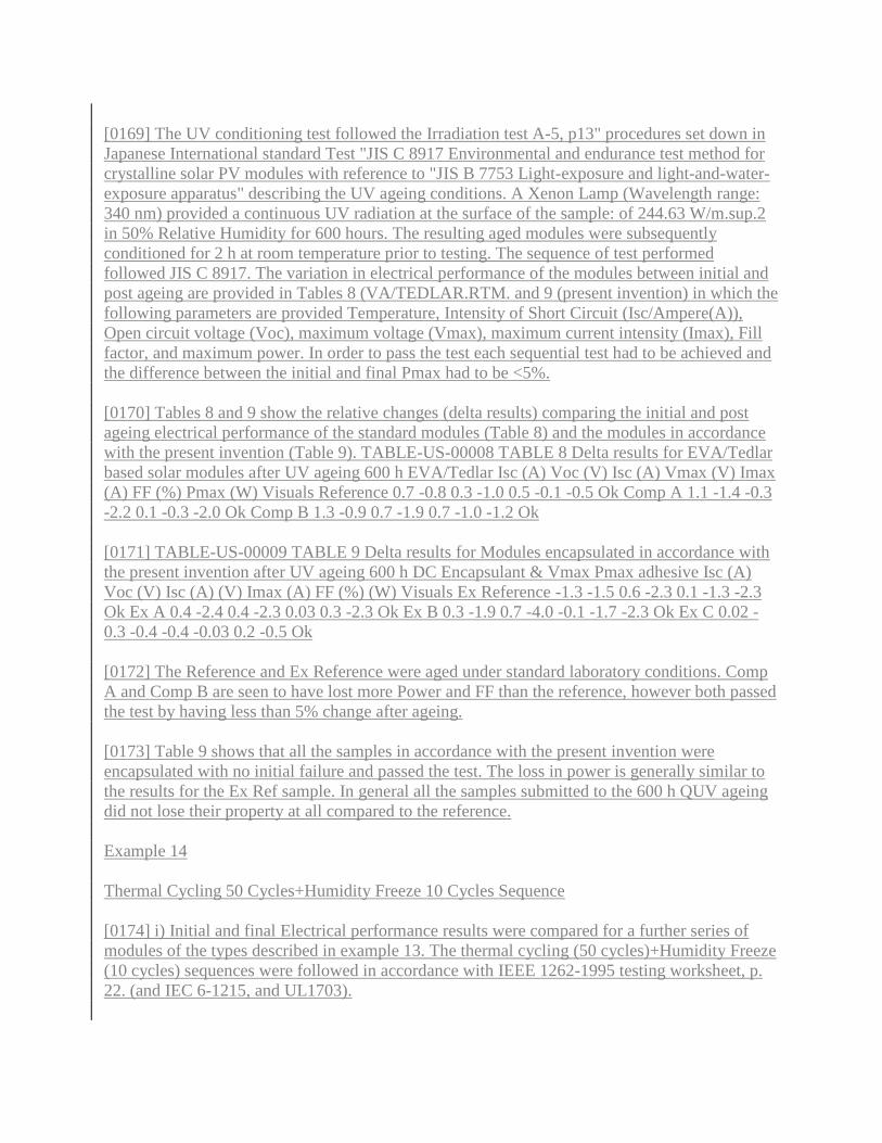
[0169] The UV conditioning test followed the Irradiation test A-5, p13" procedures set down in
Japanese International standard Test "JIS C 8917 Environmental and endurance test method for
crystalline solar PV modules with reference to "JIS B 7753 Light-exposure and light-and-water-
exposure apparatus" describing the UV ageing conditions. A Xenon Lamp (Wavelength range:
340 nm) provided a continuous UV radiation at the surface of the sample: of 244.63 W/m.sup.2
in 50% Relative Humidity for 600 hours. The resulting aged modules were subsequently
conditioned for 2 h at room temperature prior to testing. The sequence of test performed
followed JIS C 8917. The variation in electrical performance of the modules between initial and
post ageing are provided in Tables 8 (VA/TEDLAR.RTM. and 9 (present invention) in which the
following parameters are provided Temperature, Intensity of Short Circuit (Isc/Ampere(A)),
Open circuit voltage (Voc), maximum voltage (Vmax), maximum current intensity (Imax), Fill
factor, and maximum power. In order to pass the test each sequential test had to be achieved and
the difference between the initial and final Pmax had to be <5%.
[0170] Tables 8 and 9 show the relative changes (delta results) comparing the initial and post
ageing electrical performance of the standard modules (Table 8) and the modules in accordance
with the present invention (Table 9). TABLE-US-00008 TABLE 8 Delta results for EVA/Tedlar
based solar modules after UV ageing 600 h EVA/Tedlar Isc (A) Voc (V) Isc (A) Vmax (V) Imax
(A) FF (%) Pmax (W) Visuals Reference 0.7 -0.8 0.3 -1.0 0.5 -0.1 -0.5 Ok Comp A 1.1 -1.4 -0.3
-2.2 0.1 -0.3 -2.0 Ok Comp B 1.3 -0.9 0.7 -1.9 0.7 -1.0 -1.2 Ok
[0171] TABLE-US-00009 TABLE 9 Delta results for Modules encapsulated in accordance with
the present invention after UV ageing 600 h DC Encapsulant & Vmax Pmax adhesive Isc (A)
Voc (V) Isc (A) (V) Imax (A) FF (%) (W) Visuals Ex Reference -1.3 -1.5 0.6 -2.3 0.1 -1.3 -2.3
Ok Ex A 0.4 -2.4 0.4 -2.3 0.03 0.3 -2.3 Ok Ex B 0.3 -1.9 0.7 -4.0 -0.1 -1.7 -2.3 Ok Ex C 0.02 -
0.3 -0.4 -0.4 -0.03 0.2 -0.5 Ok
[0172] The Reference and Ex Reference were aged under standard laboratory conditions. Comp
A and Comp B are seen to have lost more Power and FF than the reference, however both passed
the test by having less than 5% change after ageing.
[0173] Table 9 shows that all the samples in accordance with the present invention were
encapsulated with no initial failure and passed the test. The loss in power is generally similar to
the results for the Ex Ref sample. In general all the samples submitted to the 600 h QUV ageing
did not lose their property at all compared to the reference.
Example 14
Thermal Cycling 50 Cycles+Humidity Freeze 10 Cycles Sequence
[0174] i) Initial and final Electrical performance results were compared for a further series of
modules of the types described in example 13. The thermal cycling (50 cycles)+Humidity Freeze
(10 cycles) sequences were followed in accordance with IEEE 1262-1995 testing worksheet, p.
22. (and IEC 6-1215, and UL1703).

[0175] Tables 10 and 11 provided the percentage changes in Pmax tested prior to and after
ageing. Any loss in Pmax of more than 5% is considered a failure. This test subjects samples to
ageing conditions which enable the evaluation of the prospective ability of modules to withstand
thermal expansion and contraction (through the thermal cycling) and to resist water penetration
when submitted to extreme conditions of temperature and humidity (Humidity Freeze).
[0176] Table 10 and 11 compare deltas results between the initial values and the final ones for
the standard EVA/TEDLAR.RTM. laminated solar modules (Table 10) and the solar modules
encapsulated in accordance with the present invention. TABLE-US-00010 TABLE 10
EVA/Tedlar deltas results after 50 Thermal Cycles + 10 cycles Humidity Freeze conditions
EVA/Tedlar Isc (A) Voc (V) Isc (A) Vmax (V) Imax (A) FF (%) Pmax (W) Reference 0.3 -0.9 -
0.6 -2.1 -0.5 -1.2 -2.2 Comp C -0.5 0.4 -1.4 -0.4 -0.7 0.0 -1.1 Comp D -0.1 -0.6 -1.5 -1.4 -1.7 -
1.1 -3.0 Comp E -0.7 -0.2 -1.5 -0.2 -0.1 1.5 -0.3
[0177] TABLE-US-00011 TABLE 11 Encapsulant/adhesive in accordance with the present
invention deltas results after 50 Thermal Cycles + 10 cycles Humidity Freeze conditions
Encapsulant/ adhesive Isc (A) Voc (V) Isc (A) Vmax (V) Imax (A) FF (%) Pmax (W) Reference
-1.4 -0.8 -0.8 -2.1 -0.4 -0.9 -2.5 Ex D 0.5 -1.5 -0.2 -2.7 0.5 -0.5 -2.2 Ex E -0.3 -0.8 -0.7 -1.8 -1.7
-2.5 -3.8 Ex F -0.3 -1.4 -0.2 -2.5 0.0 -0.9 -2.5
[0178] In both Tables 10 and 11, the final electrical performance results are all deemed to pass
the test (less than 5% change). Hence from the above it will be appreciated that use of an
encapsulant and in the case of this example an adhesive as described in accordance with the
present invention provides a simpler and continuous method of encapsulating solar cells as
opposed to the traditional batch/lamination processes and the resulting encapsulated solar
modules give good electrical performance results.
Example 15
[0179] Further samples as described in Example 13 were subjected to the sequence of test
commonly referred to as Damp Heat Conditioning as defined in each of IEC 6-1215, IEEE 1262,
UL1703. The results provided in Tables 12 and 13 are determined by the relative percentage
change of initial and final electrical test results. Any loss in Pmax of more than 5% was deemed
a failure. Tables 12 and 13 contrast the results between the initial and the final electrical values
ones for the two encapsulation technologies. TABLE-US-00012 TABLE 12 EVA/Tedlar deltas
results after 1000 hours in Damp Heat conditions EVA/Tedlar Isc (A) Voc (V) Isc (A) Vmax (V)
Imax (A) FF (%) Pmax (W) Reference 0.4 -2.0 0.2 -2.9 0.2 -0.9 -2.5 Comp F -0.1 -0.7 1.1 0.2 1.6
1.5 1.9 Comp G -1.1 -0.6 0.1 -1.4 0.1 -0.8 -1.2 Comp H -0.8 -0.6 0.9 -0.6 0.4 -0.3 -0.2
[0180] TABLE-US-00013 TABLE 13 Encapsulant/Adhesive deltas results after 1000 hours in
Damp Heat conditions Pmax DC Encapsulant Isc (A) Voc (V) Isc (A) Vmax (V) Imax (A) FF
(%) (W) Reference -1.5 -2.2 -0.1 -2.9 0.0 -0.6 -2.9 Ex G -0.9 -1.6 -0.6 -1.6 -0.2 0.3 -1.9 Ex H -
1.4 -1.8 -1.2 -1.0 -0.2 1.8 -1.3 Ex I 0.1 -1.1 0.1 -2.1 -0.2 -1.2 -2.2
[0181] Both tables 12 and 13 indicate that the changes in electrical properties pass the test.

You can also Monitor Keywords and Search for tracking patents relating to this Encapsulation of
solar cells patent application.
###
How KEYWORD MONITOR works... a FREEservice from FreshPatents
1. Sign up (takes 30 seconds). 2. Fill in the keywords to be monitored.
3. Each week you receive an email with patent applications related to your keywords.
Start now! - Receive info on patent apps like Encapsulation of solar cells or other areas of
interest.
###
###
Design/code © 2011 FreshContext LLC/Freshpatents.com.
Patent data source: patents published by the United States Patent and Trademark Office
(USPTO)
Information published here is for research/educational purposes only (and in conjunction with
our Keyword Monitor) and is not meant to be used in place of the full USPTO patent
document/images or a comprehensive patent archive search. Complete official applications are
on file at the USPTO and may contain additional data/images. FreshPatents.com is not affiliated
with or endorsed by the USPTO or firms/individuals or products/designs/ideas related to listed
patents and there may be applicable trademarks or servicemarks within the documents.
FreshPatents.com Support - Terms & Conditions
Thank you for viewing the Encapsulation of solar cells patent info.
- - - AAPL - Apple, BA - Boeing, GOOG - Google, IBM, JBL - Jabil, KO - Coca Cola, MOT -
MotorlaIP-related news and info
Results in 0.57145 seconds
Other interesting Freshpatents.com categories:
Computers: Graphics , I/O , Processors , Dyn. Storage , Static Storage , Printers g2