ence717 – bridge engineering steel bridges 1. behavior of composite...
TRANSCRIPT

1
ENCE717 – Bridge EngineeringSteel Bridges
Chung C. Fu, Ph.D., P.E.(http: www.best.umd.edu)
Steel Bridges
1. Behavior of Composite Steel I-Girder Bridges (7.1.1)
2. Steel I-Girder Bridge Grid-Modeling Consideration (7.1.3)
3. Principle and Modeling of Steel I-Girder Bridges (7.2)
4. Behavior of Composite Steel Box-Girder Bridges (8.1)
5. Principle and Modeling of Steel Box-Girder Bridges (8.2)
Composite Steel I-girder Bridges
• Stage 1: Erection of structural steel framing (girders and cross frames),
• Stage 2: Placement of the structural deck slab (wet concrete),
• Stage 3: Placement of appurtenances (e.g., barriers, railings, overlays) representing the long-term (LT) loading, and
• Stage 4: Bridge in-service condition (e.g., carrying live loads; vehicular, rail, pedestrian), representing the short-term (ST) loading.
Principle and Modeling of Steel I-girder Bridges
1. Beam Charts: standard beam design charts and other design aids for approximate analysis;
2. Line Girder Analysis Method: “approximate” method in the AASHTO LRFD
3. Grid Analysis Method
4. Plate and Eccentric Beam Analysis Methods5. 3D FEM Analysis Methods (next)

Line Girder Modeling
• Assumed constant deck width, parallel beams with about the same stiffness
• Developed for “design” trucks• Developed to bound within that structural
type• Limited ranges of applicability. (When
exceeded, the LRFD specifications mandate refined analysis.)
AASHTO LRFD live load distribution factor design equations for shear and moment is recommended for rating.
Line girder
Influence Lines for Moment & Shear
Moment
Shear
Truck x DF x IF
Lane x DF x IF
Composite Steel I-girder Stresses
• Total normal stress: a combination of axial stress, major axis bending stress, minor axis bending stress (not included), and warping normal (lateral bending) stress.
• Total shear stress is the sum of vertical shear stress, horizontal shear stress (not included), St. Venant torsional shear stress (generally relatively small), and warping shear stress (ignored due to different locations).
Grid Analysis
• Girders: Special-made curved element or conventional straight element• Cross-frames: X-, K- or invert K- type; internally converted from the flexibility matrix to 3 x
3 stiffness matrix, functionally similar to the Timoshenko beam with 3 D.O.F. at each end. • Diaphragms: Diaphragm is considered as conventional transverse girder with 3 D.O.F. • Deck/connection of the deck to girders: Composite action is considered for the longitudinal
girders, Equivalent deck area between nodes may be considered for deck action
Vertical DOF
Torsional DOF
Bending DOF
Default support condition:1. Vertical fix2. Bending & torsional free(may be altered by spring constants, explained later)
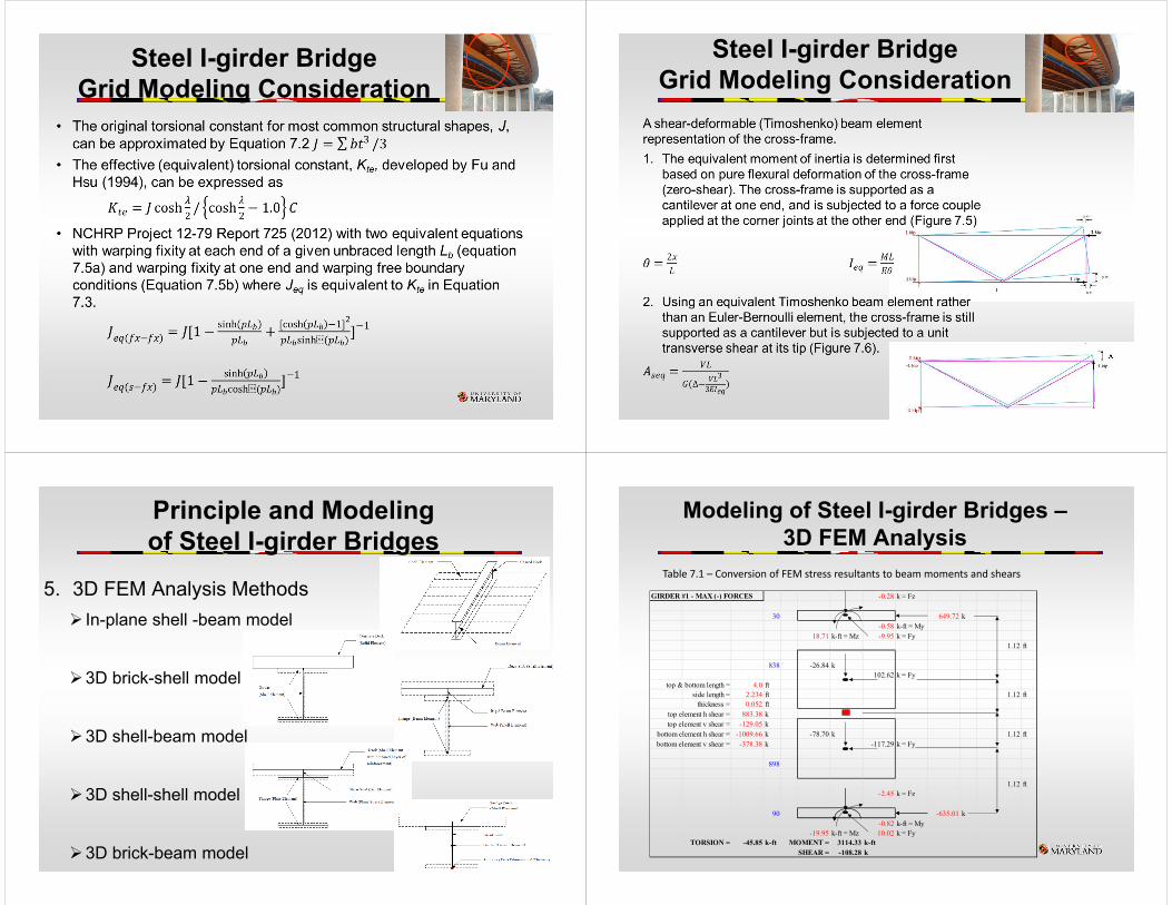
Steel I-girder Bridge Grid Modeling Consideration
Steel I-girder Bridge Grid Modeling Consideration
Principle and Modeling of Steel I-girder Bridges
5. 3D FEM Analysis Methods In-plane shell -beam model
3D brick-shell model
3D shell-beam model
3D shell-shell model
3D brick-beam model
Modeling of Steel I-girder Bridges –3D FEM Analysis
Table 7.1 – Conversion of FEM stress resultants to beam moments and shears
GIRDER #1 - MAX (-) FORCES -0.28 k = Fz
30 649.72 k-0.58 k-ft = My
18.71 k-ft = Mz -9.95 k = Fy1.12 ft
838 -26.84 k102.62 k = Fy
top & bottom length = 4.0 ftside length = 2.234 ft 1.12 ft thickness = 0.052 ft
top element h shear = 883.38 ktop element v shear = -129.05 k
bottom element h shear = -1009.66 k -78.70 k 1.12 ftbottom element v shear = -378.38 k -117.29 k = Fy
898
1.12 ft-2.45 k = Fz
90 -635.01 k-0.82 k-ft = My
-19.95 k-ft = Mz 10.02 k = FyTORSION = -45.85 k-ft MOMENT = 3114.33 k-ft
SHEAR = -108.28 k

Principle and Modeling of Steel I-girder Bridges
• Sample Influence Surfaces of a Curved Steel I-girder Bridges (a) Inner Girder In-span Bending Moment at C; (b) Inner Girder Interior Support Bending Moment at G; (c) Outer Girder Interior Support Bending Moment at D; (d) Second Interior Girder Interior Support Reaction at F
(a) (b)
(c) (d)
Principle and Modeling of Steel I-girder Bridges
Figure 7.20 ‐ Cross‐section view of a girder‐substringer system
Straddle bent cap modeled by support stiffness
Grid Model Spring Elements to model Different Boundary Conditions
(Ramp FR-A over SR 6060, Pittsburgh, PA)Steel Bridges
1. Behavior of Composite Steel I-Girder Bridges (7.1.1)
2. Steel I-Girder Bridge Grid-Modeling Consideration (7.1.3)
3. Principle and Modeling of Steel I-Girder Bridges (7.2)
4. Behavior of Composite Steel Box-Girder Bridges (8.1)
5. Principle and Modeling of Steel Box-Girder Bridges (8.2)

Behavior of Steel Box-girder Bridges
Figure 8.1 ‐ Steel box girders: (a) Unstiffened closed box girder; (b) Unstiffened tub girder with lateral bracing;(c) (c) Stiffened closed box girder
(c)
Equivalent thickness of the top bracing for the quasi-closed box
18
Behavior of Steel Box-girder Bridges
Internal vertical cross‐frame
External cross‐frame
Top lateral bracing system
Composite Steel Box-girder Bridges
• Figure 8.9 illustrates the general box girder normal stresses which can occur in a curved or skewed box-shaped girder.
• Closed box sections are extremely efficient at carrying torsion by means of St. Venant torsional shear flow (Figure 8.10). When combined with vertical shear in the webs, this shear flow is always subtractive in one web and additive in the other.

Box Girder Bottom Flange under In-plane Action
(a) Unstiffened plate with small aspect ratio a/b(b) (b) Unstiffened plate with large aspect ratio a/b
(c) Stiffened plate
Modeling of a Twin-box Girder Bridge
• 2D Grillage model• 3D Brick-Shell model• 3D Shell-Shell model
High Load Multi-Rotational bearingsfor Girder Bridges
(a) Disk bearing(b) Pot bearing(c) Spherical bearing
3D Beam Element Model with Boundary Conditions and Their Reactions