enclosure air leakage testing: what’s new and what’s … · enclosure air leakage testing:...
TRANSCRIPT

Enclosure Air Leakage Testing:
What’s New and What’s Coming?
RESNET Annual Conference
Atlanta, GA
February 26, 2014
Theresa Weston, PhD.
DuPont Building Knowledge Center

Learning Objectives:
� Understand Energy Code air barrier and building air leakage requirements
� Learn air leakage requirement changes coming in the 2015 IECC
� Understand the different air leakage test method standards
� Learn what developments in ASTM air leakage test methods are underway
© E. I. DuPont de Nemours and Company 2014. All rights reserved
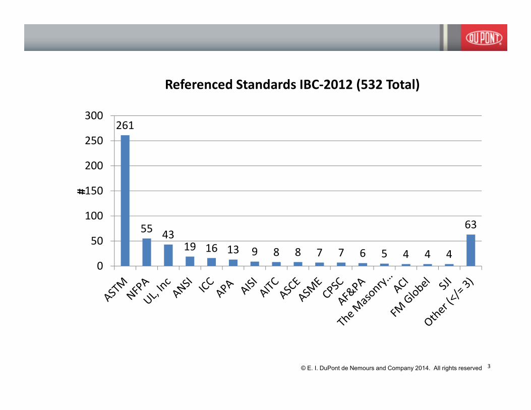
261
5543
19 16 13 9 8 8 7 7 6 5 4 4 4
63
0
50
100
150
200
250
300
#
Referenced Standards IBC-2012 (532 Total)
3© E. I. DuPont de Nemours and Company 2014. All rights reserved
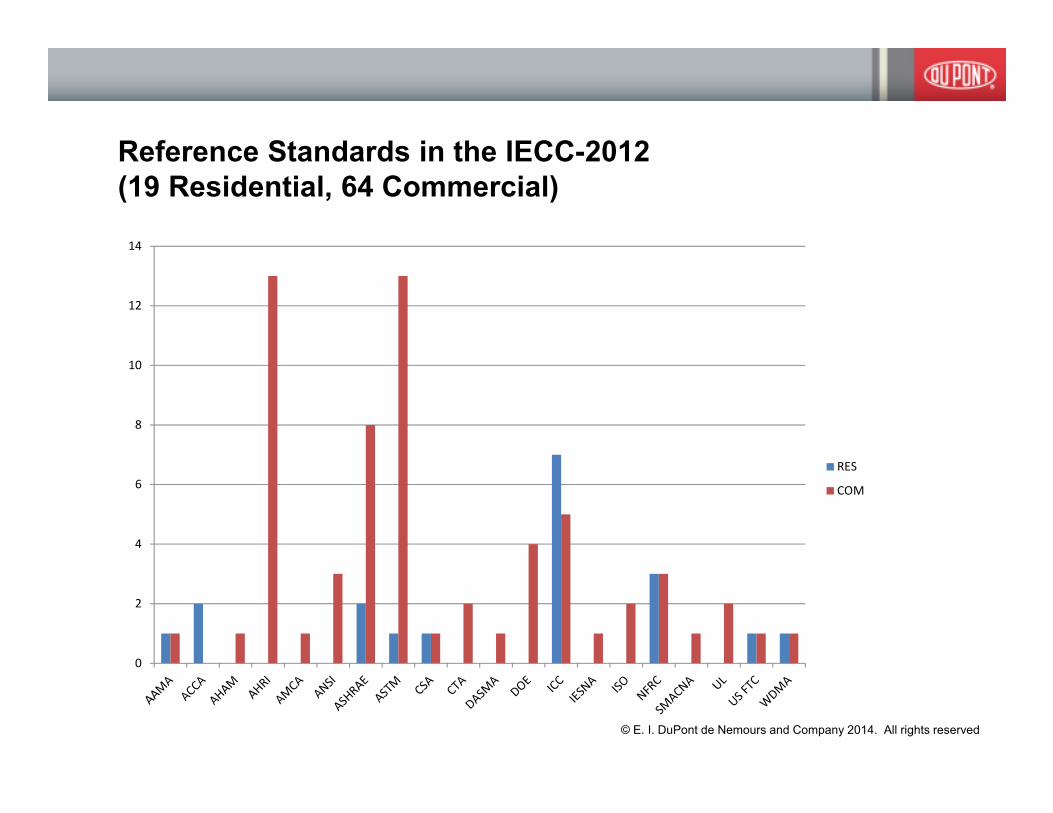
Reference Standards in the IECC-2012
(19 Residential, 64 Commercial)
0
2
4
6
8
10
12
14
RES
COM
© E. I. DuPont de Nemours and Company 2014. All rights reserved

Home For Sale by Owner
110 W. King Place, Nome, Alaska
This 2,009 square foot superinsulated energy-efficient and low maintenance
home includes a 364 square foot heated garage with cement floor. It's one of
Nome's finest houses, located on a 7,700 square foot lot (55 x 140), in an
extremely convenient location. It's less than a five-minute walk from
downtown, from Nome's Safeway store, and from nine of Nome's
churches. There's room in front of the house to park a second vehicle off the
street.
The home is bright and cheerful, w ith three bedrooms and two baths, a
sunny 12-foot by 18-foot living room with a high vaulted ceiling with pine
paneling, a large 10-foot by 11-foot kitchen with an integral 3-foot pantry, a 9-
foot by 12-foot dining room, and a 20 -foot by 24-foot den, which includes a 5-
foot by 8-foot office that can easily be converted to a third full bathroom.
In 1999, the kitchen and bathrooms were completely remodeled with new
oak Kitchen Maid cabinets and Corian countertops, lavatories and shower/tub
surrounds.
“In 1993, the home was re-sheathed in “a housewrap” with all joints
carefully glued with acoustic sealant (thirty tubes of it!), providing
extreme protection from wind. (Although the 1993 addition
increased floor space by 30%, our heating bills actually dropped.)”
© E. I. DuPont de Nemours and Company 2014. All rights reserved

Performance
Testing
Photos courtesy of Construction Instruction

7www.energycode.gov

IECC Residential – Compliance Paths
Prescriptive
Path
Performance
Path
Energy Rating
Index Path
(2015)
2015 IECC
Some jurisdictions, currently :
• New Mexico
• Local Adoption in
Arkansas, Colorado, Idaho,
Kansas, Massachusetts,
New York
© E. I. DuPont de Nemours and Company 2014. All rights reserved

IECC Residential – Mandatory Provisions
Qualitative
requirement and
location list
2006
402.4.1 Building thermal envelope. The building thermal envelope
shall be durably sealed to limit infiltration. The
sealing methods between dissimilar materials shall allow for differential
expansion and contraction. The following shall be caulked, gasketed,
weatherstripped or otherwise sealed with an air barrier material,
suitable film or solid material:
1. All joints, seams and penetrations.
2. Site-built windows, doors and skylights.
3. Openings between window and door assemblies and their
respective jambs and framing.
4. Utility penetrations.
5. Dropped ceilings or chases adjacent to the thermal envelope.
6. Knee walls.
7. Walls and ceilings separating a garage from conditioned spaces.
8. Behind tubs and showers on exterior walls.
9. Common walls between dwelling units.
10. Other sources of infiltration
© E. I. DuPont de Nemours and Company 2014. All rights reserved

IECC Residential – Mandatory Provisions
Qualitative
requirement and
location list
Compliance
options:
Visual Inspection
or
Testing
< 7 ACH50
Qualitative
requirement and
location list
2006 2009© E. I. DuPont de Nemours and Company 2014. All rights reserved
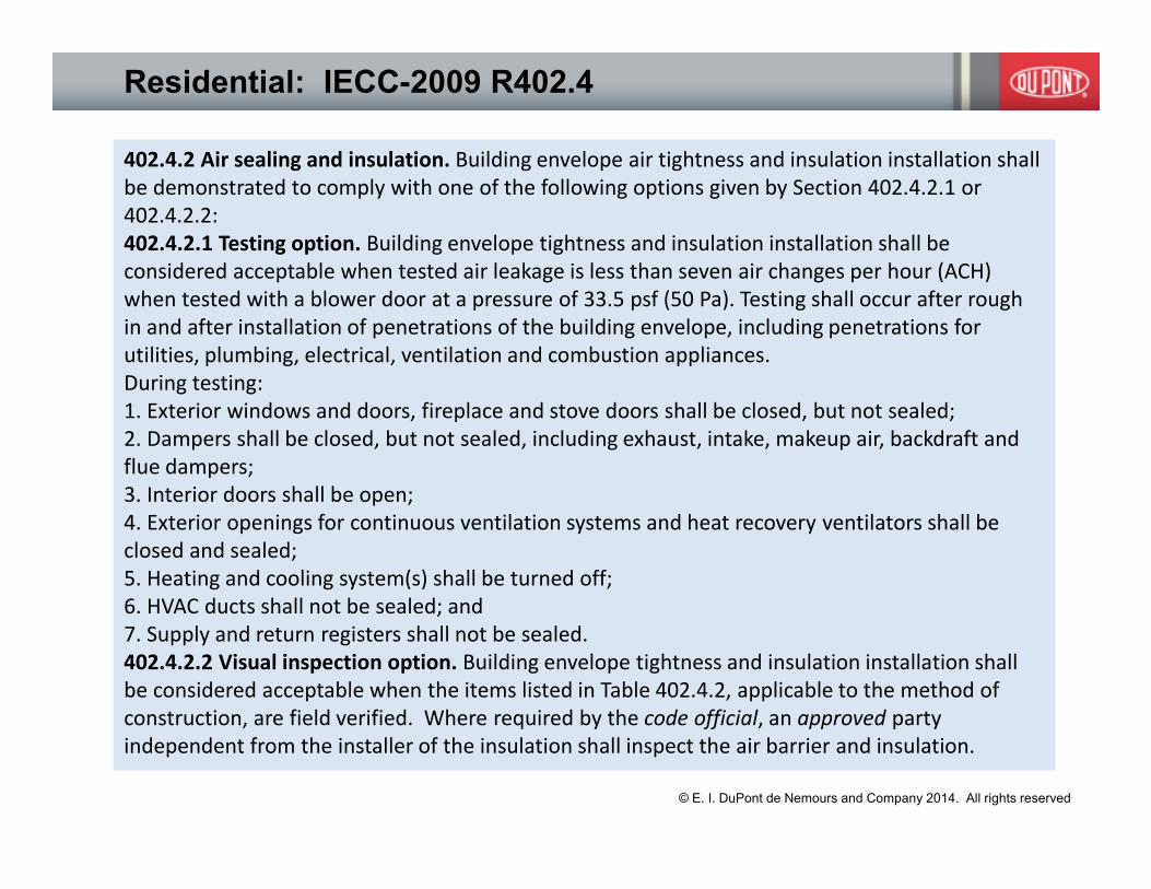
Residential: IECC-2009 R402.4
402.4.2 Air sealing and insulation. Building envelope air tightness and insulation installation shall
be demonstrated to comply with one of the following options given by Section 402.4.2.1 or
402.4.2.2:
402.4.2.1 Testing option. Building envelope tightness and insulation installation shall be
considered acceptable when tested air leakage is less than seven air changes per hour (ACH)
when tested with a blower door at a pressure of 33.5 psf (50 Pa). Testing shall occur after rough
in and after installation of penetrations of the building envelope, including penetrations for
utilities, plumbing, electrical, ventilation and combustion appliances.
During testing:
1. Exterior windows and doors, fireplace and stove doors shall be closed, but not sealed;
2. Dampers shall be closed, but not sealed, including exhaust, intake, makeup air, backdraft and
flue dampers;
3. Interior doors shall be open;
4. Exterior openings for continuous ventilation systems and heat recovery ventilators shall be
closed and sealed;
5. Heating and cooling system(s) shall be turned off;
6. HVAC ducts shall not be sealed; and
7. Supply and return registers shall not be sealed.
402.4.2.2 Visual inspection option. Building envelope tightness and insulation installation shall
be considered acceptable when the items listed in Table 402.4.2, applicable to the method of
construction, are field verified. Where required by the code official, an approved party
independent from the installer of the insulation shall inspect the air barrier and insulation.
© E. I. DuPont de Nemours and Company 2014. All rights reserved

© E. I. DuPont de Nemours and Company 2014. All rights reserved

IECC Residential – Mandatory Provisions
Qualitative
requirement and
location list
Compliance
options:
Visual Inspection
or
Testing
< 7 ACH50
Compliance:
Visual Inspection
and
Testing
Z1,2: < 5ACH50
Z3-8:: < 3ACH50
Qualitative
requirement and
location list
2006 2009 2012
© E. I. DuPont de Nemours and Company 2014. All rights reserved
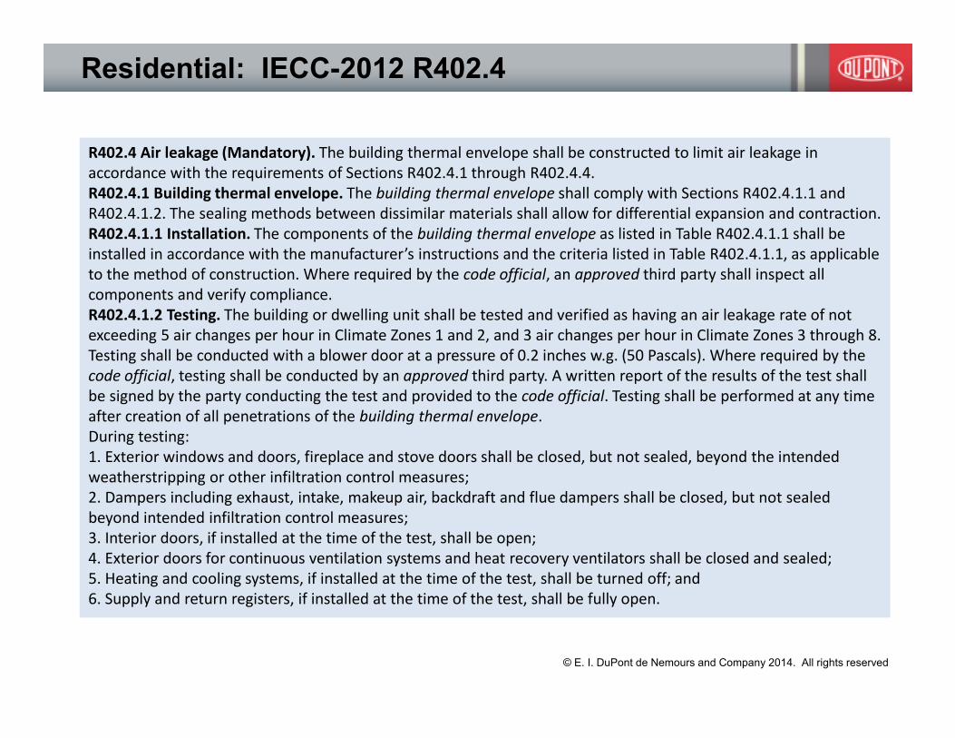
Residential: IECC-2012 R402.4
R402.4 Air leakage (Mandatory). The building thermal envelope shall be constructed to limit air leakage in
accordance with the requirements of Sections R402.4.1 through R402.4.4.
R402.4.1 Building thermal envelope. The building thermal envelope shall comply with Sections R402.4.1.1 and
R402.4.1.2. The sealing methods between dissimilar materials shall allow for differential expansion and contraction.
R402.4.1.1 Installation. The components of the building thermal envelope as listed in Table R402.4.1.1 shall be
installed in accordance with the manufacturer’s instructions and the criteria listed in Table R402.4.1.1, as applicable
to the method of construction. Where required by the code official, an approved third party shall inspect all
components and verify compliance.
R402.4.1.2 Testing. The building or dwelling unit shall be tested and verified as having an air leakage rate of not
exceeding 5 air changes per hour in Climate Zones 1 and 2, and 3 air changes per hour in Climate Zones 3 through 8.
Testing shall be conducted with a blower door at a pressure of 0.2 inches w.g. (50 Pascals). Where required by the
code official, testing shall be conducted by an approved third party. A written report of the results of the test shall
be signed by the party conducting the test and provided to the code official. Testing shall be performed at any time
after creation of all penetrations of the building thermal envelope.
During testing:
1. Exterior windows and doors, fireplace and stove doors shall be closed, but not sealed, beyond the intended
weatherstripping or other infiltration control measures;
2. Dampers including exhaust, intake, makeup air, backdraft and flue dampers shall be closed, but not sealed
beyond intended infiltration control measures;
3. Interior doors, if installed at the time of the test, shall be open;
4. Exterior doors for continuous ventilation systems and heat recovery ventilators shall be closed and sealed;
5. Heating and cooling systems, if installed at the time of the test, shall be turned off; and
6. Supply and return registers, if installed at the time of the test, shall be fully open.
© E. I. DuPont de Nemours and Company 2014. All rights reserved

IECC Residential – Prescriptive Path
Qualitative
requirement and
location list
Compliance
options:
Visual Inspection
or
Testing
< 7 ACH50
Compliance:
Visual Inspection
and
Testing
Z1,2: < 5ACH50
Z3-8:: < 3ACH50
Qualitative
requirement and
location list
Compliance:
Visual Inspection
and
Testing
Z1,2: < 5ACH50
Z3-8:: < 3ACH50
2006 2009 2012 2015
© E. I. DuPont de Nemours and Company 2014. All rights reserved

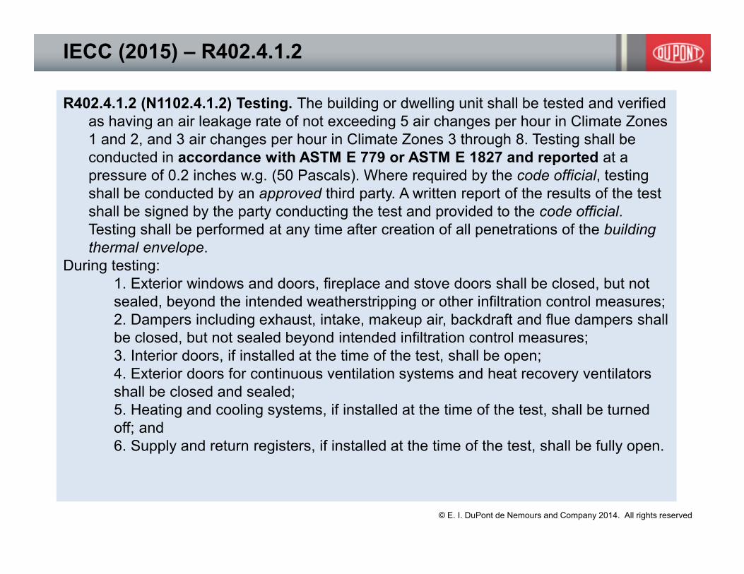
IECC (2015) – R402.4.1.2
R402.4.1.2 (N1102.4.1.2) Testing. The building or dwelling unit shall be tested and verified
as having an air leakage rate of not exceeding 5 air changes per hour in Climate Zones
1 and 2, and 3 air changes per hour in Climate Zones 3 through 8. Testing shall be
conducted in accordance with ASTM E 779 or ASTM E 1827 and reported at a
pressure of 0.2 inches w.g. (50 Pascals). Where required by the code official, testing
shall be conducted by an approved third party. A written report of the results of the test
shall be signed by the party conducting the test and provided to the code official.
Testing shall be performed at any time after creation of all penetrations of the building
thermal envelope.
During testing:
1. Exterior windows and doors, fireplace and stove doors shall be closed, but not
sealed, beyond the intended weatherstripping or other infiltration control measures;
2. Dampers including exhaust, intake, makeup air, backdraft and flue dampers shall
be closed, but not sealed beyond intended infiltration control measures;
3. Interior doors, if installed at the time of the test, shall be open;
4. Exterior doors for continuous ventilation systems and heat recovery ventilators
shall be closed and sealed;
5. Heating and cooling systems, if installed at the time of the test, shall be turned
off; and
6. Supply and return registers, if installed at the time of the test, shall be fully open.
© E. I. DuPont de Nemours and Company 2014. All rights reserved

Performance Path – 2006 / 2009 IECC Residential
BUILDING
COMPONENT
STANDARD
REFERENCE
DESIGN
PROPOSED DESIGN
Air exchange
rate
Specific
Leakage Area
(SLA)d =
0.00036
assuming no
energy
recovery
For residences that are not tested, the same as the
standard reference design.
For residences without mechanical ventilation that
are tested in accordance with ASHRAE 119,
Section 5.1, the measured air exchange
rate but not less than 0.35 ACH
For residences with mechanical ventilation that are
tested in accordance with ASHRAE 119, Section 5.1,
the measured air exchange rate combined with the
mechanical ventilation rate, f which shall not be less
than 0.01 × CFA + 7.5 × (Nbr+1) where:
CFA = conditioned floor area
Nbr = number of bedrooms
© E. I. DuPont de Nemours and Company 2014. All rights reserved
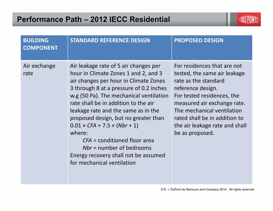
Performance Path – 2012 IECC Residential
BUILDING
COMPONENT
STANDARD REFERENCE DESIGN PROPOSED DESIGN
Air exchange
rate
Air leakage rate of 5 air changes per
hour in Climate Zones 1 and 2, and 3
air changes per hour in Climate Zones
3 through 8 at a pressure of 0.2 inches
w.g (50 Pa). The mechanical ventilation
rate shall be in addition to the air
leakage rate and the same as in the
proposed design, but no greater than
0.01 × CFA + 7.5 × (Nbr + 1)
where:
CFA = conditioned floor area
Nbr = number of bedrooms
Energy recovery shall not be assumed
for mechanical ventilation
For residences that are not
tested, the same air leakage
rate as the standard
reference design.
For tested residences, the
measured air exchange rate.
The mechanical ventilation
rated shall be in addition to
the air leakage rate and shall
be as proposed.
© E. I. DuPont de Nemours and Company 2014. All rights reserved

Commercial: IECC-2006/2009 502.4 Air leakage.
(Mandatory).
20
502.4.3 Sealing of the building envelope. Openings and penetrations in the building
envelope shall be sealed with caulking materials or closed with gasketing systems
compatible with the construction materials and location. Joints and seams shall be
sealed in the same manner or taped or covered with a moisture vapor-permeable
wrapping material. Sealing materials spanning joints between construction
materials shall allow for expansion and contraction of the construction materials.

IECC(2012) Commercial (Mandatory)
C402.4.1 Air barriers. A continuous air barrier shall be provided throughout the building
thermal envelope. The air barriers shall be permitted to be located on the inside or outside of
the building envelope, located within the assemblies composing the envelope, or any
combination thereof. The air barrier shall comply with Sections C402.4.1.1 and C402.4.1.2.
Exception: Air barriers are not required in buildings located in Climate Zones 1, 2 and 3.
Air barrier
compliance
options.
C402.4.1.2.1 Materials. Materials with an air permeability no greater than
0.004 cfm/ft2 (0.02 L/s � m2) under a pressure differential of 0.3 inches water
gauge (w.g.) (75 Pa) when tested in accordance with ASTM E 2178 shall
comply with this section..
C402.4.1.2.2 Assemblies. Assemblies of materials and components with an
average air leakage not to exceed 0.04 cfm/ft2 (0.2 L/s � m2) under a
pressure differential of 0.3 inches of water gauge (w.g.)(75 Pa) when tested in
accordance with ASTM E 2357, ASTM E 1677 or ASTM E 283 shall comply
with this section
C402.4.1.2.3 Building test. The completed building shall be tested and the
air leakage rate of the building envelope shall not exceed 0.40 cfm/ft2 at a
pressure differential of 0.3 inches water gauge (2.0 L/s � m2 at 75 Pa) in
accordance with ASTM E 779 or an equivalent method approved by the code
official.
© E. I. DuPont de Nemours and Company 2014. All rights reserved
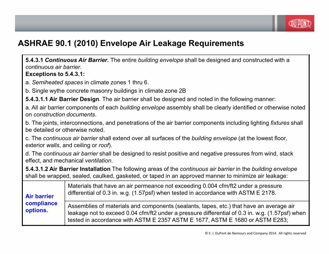
ASHRAE 90.1 (2010) Envelope Air Leakage Requirements
5.4.3.1 Continuous Air Barrier. The entire building envelope shall be designed and constructed with a
continuous air barrier.
Exceptions to 5.4.3.1:
a. Semiheated spaces in climate zones 1 thru 6.
b. Single wythe concrete masonry buildings in climate zone 2B
5.4.3.1.1 Air Barrier Design. The air barrier shall be designed and noted in the following manner:
a. All air barrier components of each building envelope assembly shall be clearly identified or otherwise noted
on construction documents.
b. The joints, interconnections, and penetrations of the air barrier components including lighting fixtures shall
be detailed or otherwise noted.
c. The continuous air barrier shall extend over all surfaces of the building envelope (at the lowest floor,
exterior walls, and ceiling or roof).
d. The continuous air barrier shall be designed to resist positive and negative pressures from wind, stack
effect, and mechanical ventilation.
5.4.3.1.2 Air Barrier Installation The following areas of the continuous air barrier in the building envelope
shall be wrapped, sealed, caulked, gasketed, or taped in an approved manner to minimize air leakage:
Air barrier
compliance
options.
Materials that have an air permeance not exceeding 0.004 cfm/ft2 under a pressure
differential of 0.3 in. w.g. (1.57psf) when tested in accordance with ASTM E 2178.
Assemblies of materials and components (sealants, tapes, etc.) that have an average air
leakage not to exceed 0.04 cfm/ft2 under a pressure differential of 0.3 in. w.g. (1.57psf) when
tested in accordance with ASTM E 2357 ASTM E 1677, ASTM E 1680 or ASTM E283;
© E. I. DuPont de Nemours and Company 2014. All rights reserved

IECC(2015) Commercial (Mandatory)
C402.4 Air leakage (Mandatory). The thermal envelope of buildings shall comply with
Sections C402.4.1 through C402.4.8. Alternatively the building thermal envelope shall
be permitted to be tested in accordance with ASTM E779 at a pressure differential of
0.3 inches water gauge, or an equivalent method approved by the code official, and
deemed to comply with the provisions of this section when the tested air leakage rate
of the building thermal envelope does not exceed 0.40 cfm/ft2. Where compliance is
based on such testing the building shall also comply with Sections C402.4.5, 402.4.6
and 402.4.7.
C402.4.1 Air barriers. A continuous air barrier shall be provided throughout the building
thermal envelope. The air barriers shall be permitted to be located on the inside or
outside of the building envelope, located within the assemblies composing the
envelope, or any combination thereof. The air barrier shall comply with Sections
C402.4.1.1 and C402.4.1.2.
Exception: Air barriers are not required in buildings located in Climate Zone 2B
© E. I. DuPont de Nemours and Company 2014. All rights reserved

Referenced Test Standards
Material Commercial ASTM E2178
Assembly Commercial ASTM E283
Assembly Commercial ASTM E1677
Assembly Commercial ASTM E2357
Assembly Commercial (ASHRAE 90.1) ASTM E1680
Whole Building Residential / Commercial ASTM E779
Whole Building Residential ASTM E1827
Whole Building Residential ASHRAE 119,
Section 5.1
� ASTM E779 or
� CGSB 149
© E. I. DuPont de Nemours and Company 2014. All rights reserved
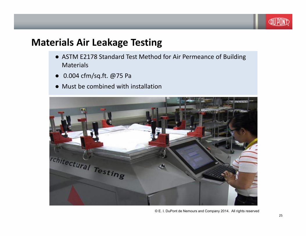
● ASTM E2178 Standard Test Method for Air Permeance of Building
Materials
● 0.004 cfm/sq.ft. @75 Pa
● Must be combined with installation
Materials Air Leakage Testing
25
© E. I. DuPont de Nemours and Company 2014. All rights reserved

Air Barrier Materials – ASTM E2178
0
0.005
0.01
0.015
0.02
0.025
0 50 100 150 200 250 300 350
Pa
L/s/m
2
#1 #2 #3
Diagram from CCMC Technical Guide for Air Barrier Materials Testing
Current method is defined for flexible
sheet and rigid boards. Standard
specimen preparation for fluid applied
materials still being developed.
© E. I. DuPont de Nemours and Company 2014. All rights reserved

Code Evaluation Reports
Internal Use Only
© E. I. DuPont de Nemours and Company 2014. All rights reserved

� ASTM E283 Test Method for
Determining Rate of Air Leakage
Through Exterior Windows, Curtain
Walls, and Doors Under Specified
Pressure Differences Across the
Specimen
� ASTM E1677 Standard Specification for
an Air Barrier (AB) Material or System
for Low-Rise Framed Building Walls
� ASTM E2357 Standard Test Method for
Determining Air Leakage of Air Barrier
Assemblies
� ASTM E1680 Standard Test Method for
Rate of Air Leakage Through Exterior
Metal Roof Panel Systems
� 0.04 cfm/sq.ft. @75 Pa
28
Assembly Air Leakage Testing
Testing of air barrier assemblies is an
essential step to demonstrate
performance of installed air barriers
© E. I. DuPont de Nemours and Company 2014. All rights reserved
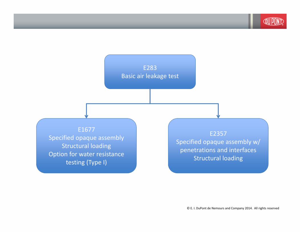
E283
Basic air leakage test
E1677
Specified opaque assembly
Structural loading
Option for water resistance
testing (Type I)
E2357
Specified opaque assembly w/
penetrations and interfaces
Structural loading
© E. I. DuPont de Nemours and Company 2014. All rights reserved
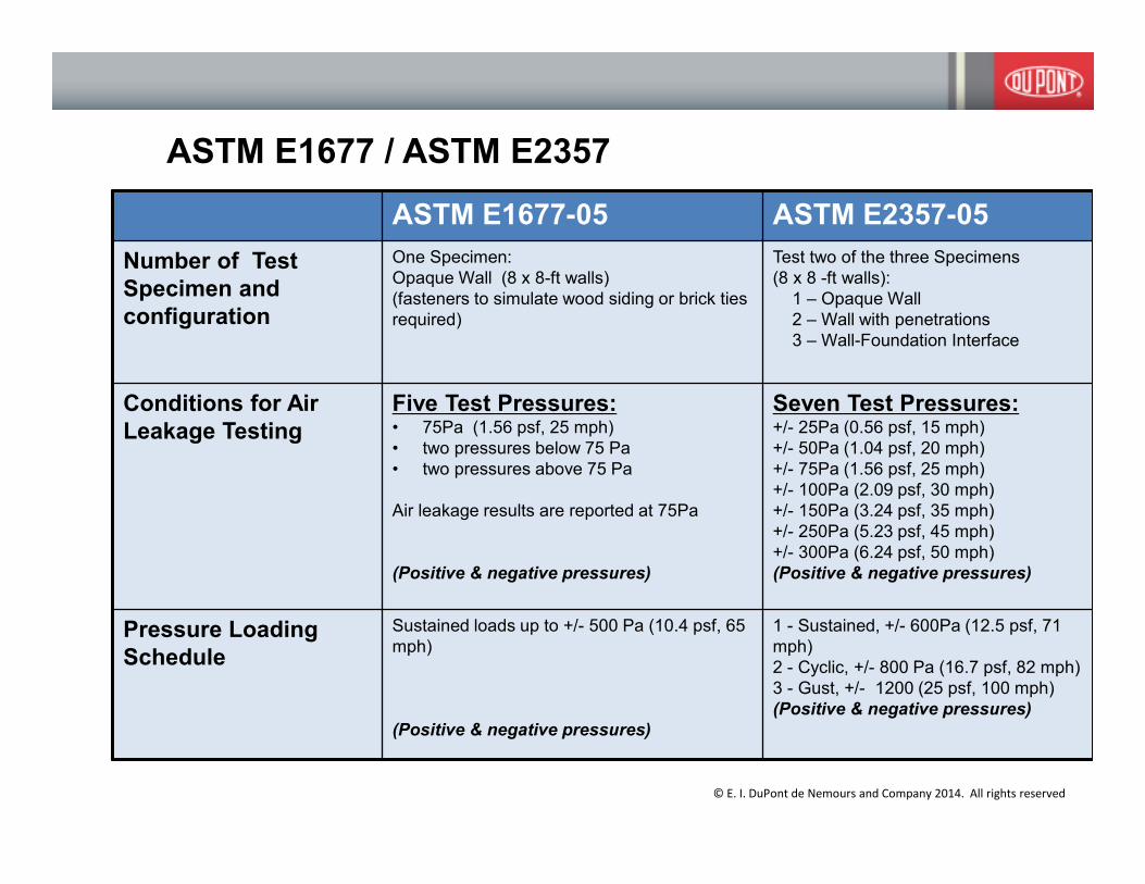
ASTM E1677 / ASTM E2357
ASTM E1677-05 ASTM E2357-05
Number of Test
Specimen and
configuration
One Specimen:
Opaque Wall (8 x 8-ft walls)
(fasteners to simulate wood siding or brick ties
required)
Test two of the three Specimens
(8 x 8 -ft walls):
1 – Opaque Wall
2 – Wall with penetrations
3 – Wall-Foundation Interface
Conditions for Air
Leakage Testing
Five Test Pressures: • 75Pa (1.56 psf, 25 mph)
• two pressures below 75 Pa
• two pressures above 75 Pa
Air leakage results are reported at 75Pa
(Positive & negative pressures)
Seven Test Pressures:+/- 25Pa (0.56 psf, 15 mph)
+/- 50Pa (1.04 psf, 20 mph)
+/- 75Pa (1.56 psf, 25 mph)
+/- 100Pa (2.09 psf, 30 mph)
+/- 150Pa (3.24 psf, 35 mph)
+/- 250Pa (5.23 psf, 45 mph)
+/- 300Pa (6.24 psf, 50 mph)
(Positive & negative pressures)
Pressure Loading
Schedule
Sustained loads up to +/- 500 Pa (10.4 psf, 65
mph)
(Positive & negative pressures)
1 - Sustained, +/- 600Pa (12.5 psf, 71
mph)
2 - Cyclic, +/- 800 Pa (16.7 psf, 82 mph)
3 - Gust, +/- 1200 (25 psf, 100 mph)
(Positive & negative pressures)
© E. I. DuPont de Nemours and Company 2014. All rights reserved

31
© E. I. DuPont de Nemours and Company 2014. All rights reserved

Illustrations for ASTM E2357
© E. I. DuPont de Nemours and Company 2014. All rights reserved

ASTM E1677: Two Air Barrier Classifications
Performance
Properties
AB Classifications
Type I Type II
Air leakageAs tested by E283
< .06 cfm/ft² @ 75 Pa
Structural IntegrityAs tested by E330 2 in. H20 or 500 Pa (65 mph) for 1 hr in each direction
Water Resistance
As tested by E331
Water Vapor
PermeanceAs tested by E96A
Measured
No penetration for 15
min of simulated wind
driven rain @ 0.11 H2O
or 27 Pa (15 mph)
Not Required
© E. I. DuPont de Nemours and Company 2014. All rights reserved

� ASTM E779 Standard Test Method for
Determining Air Leakage Rate by Fan
Pressurization
� ASTM E1827 Standard Test Methods
for Determining Airtightness of
Buildings Using an Orifice Blower Door
� CAN/CGSB-149.10-M86, Standard for
Determination of Airtightness of
Buildings by the Fan Depressurization
Method
34
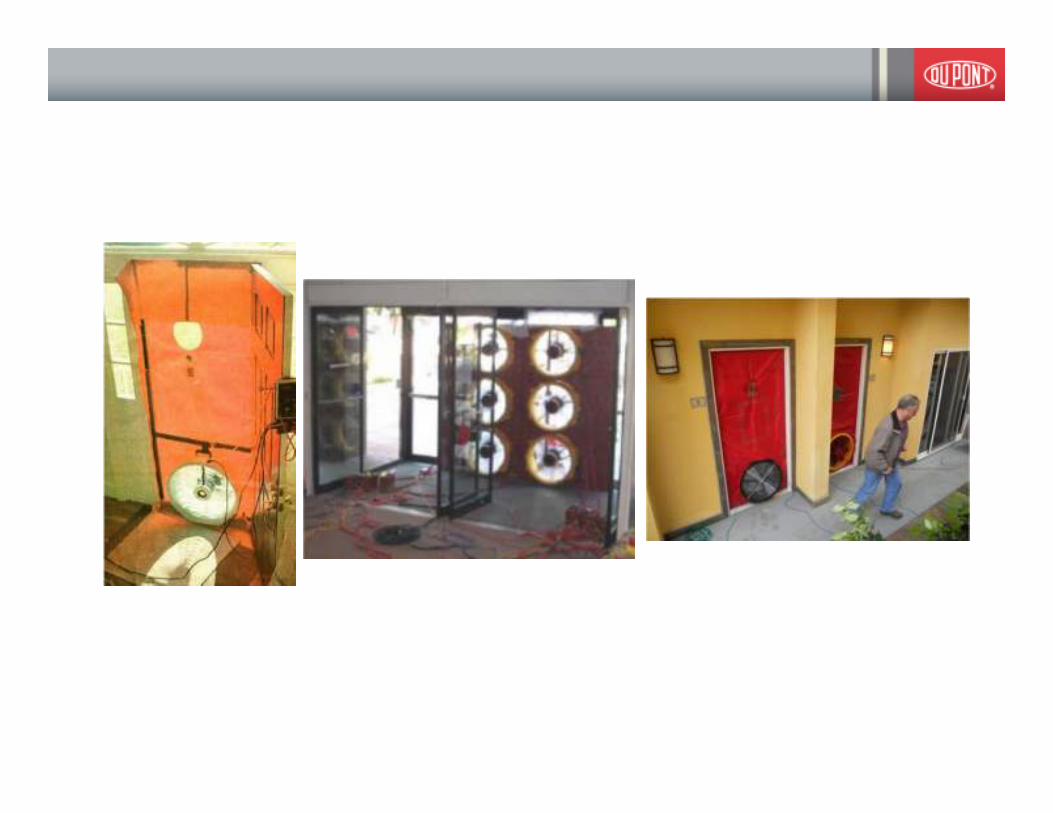
Building Air Leakage Testing
Testing whole building at the end of the
project may be too late and/or too
expensive to fix mistakesPhotos courtesy Pie Forensic Consultants
© E. I. DuPont de Nemours and Company 2014. All rights reserved
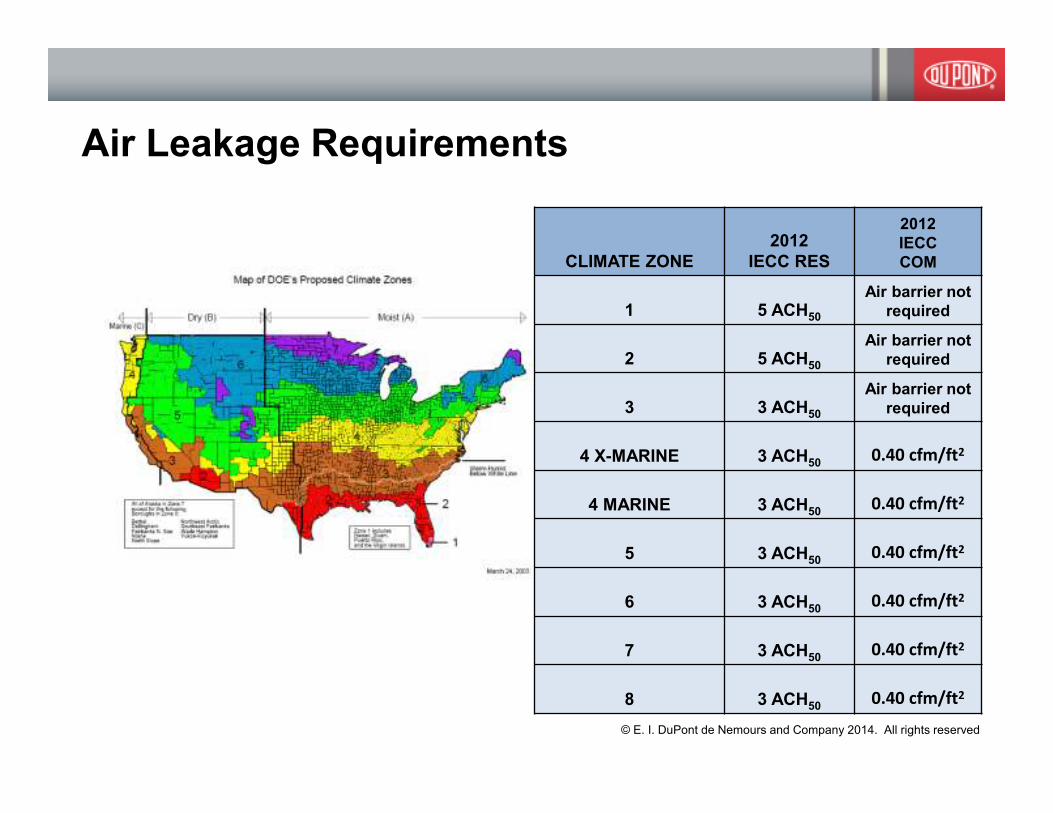
Air Leakage Requirements
CLIMATE ZONE
2012
IECC RES
2012
IECC
COM
1 5 ACH50
Air barrier not
required
2 5 ACH50
Air barrier not
required
3 3 ACH50
Air barrier not
required
4 X-MARINE 3 ACH500.40 cfm/ft2
4 MARINE 3 ACH500.40 cfm/ft2
5 3 ACH500.40 cfm/ft2
6 3 ACH500.40 cfm/ft2
7 3 ACH500.40 cfm/ft2
8 3 ACH500.40 cfm/ft2
© E. I. DuPont de Nemours and Company 2014. All rights reserved

Comparison of Building Air Leakage Test Standards
Standard Test Conditions Measurement
Protocol
Metric Reference
Pressure
Building Type
ASTM E779 Pressurization &
Depressurization
Multi-point
Measurement
Equivalent
Leakage Area
4 Pa single zone
CGSB 149 Pressurization Multi-point
Measurement
Equivalent
Leakage Area
none specified small detached
buildings
ASTM E1827 Pressurizaton,
Depressurization
or Both
Single-point
and dual point
methods
Air Leakage 50 Pa single zone
RESNET Ch 8 Pressurization or
Depressurization
Single-point,
multi-point,
repeated
single-point
Air Leakage 50 Pa low rise, three
stories or less,
residential and
light commercial
buildings
© E. I. DuPont de Nemours and Company 2014. All rights reserved

38© E. I. DuPont de Nemours and Company 2014. All rights reserved

� Harmonization
� Additional Applications
� Support Compliance
© E. I. DuPont de Nemours and Company 2014. All rights reserved

Harmonization
Whole Building Residential / Commercial E779
Whole Building Residential E1827
Whole Building Residential ASHRAE 119,
Section 5.1 � ASTM
E779 or CGSB 149
© E. I. DuPont de Nemours and Company 2014. All rights reserved

IECC-Residential ASTM E779 RESNET Chapter 8
Exterior windows and doors, fireplace and
stove doors shall be closed, but not sealed,
beyond the intended weatherstripping or
other infiltration control measures;
Doors and windows that are part of the conditioned
space boundary shall be
closed and latched.
Operable window trickle-vents and through-the-wall
vents: Shall be closed.
Interior doors, if installed at the time of the
test, shall be open;
All interconnecting doors in the conditioned space shall
be open such that a uniform pressure shall be maintained
within the conditioned space to within 610 % of the
measured inside/outside pressure difference.
Interior Doors: Shall be open within the Conditioned
Space Boundary.
Attached garages: All exterior garage doors and
windows shall be closed and latched unless the
blower door is installed between the house and the
garage, in which case the garage shall be opened to
outside by opening at least one exterior garage
door.
Crawlspaces: If a crawlspace is inside the
conditioned space boundary, interior
access doors and hatches between the house and
the crawlspace shall be opened and exterior
crawlspace access doors, vents and hatches shall be
closed. If a crawlspace is outside the conditioned
space boundary, interior access doors and hatches
shall be closed. For compliance testing purposes,
crawl-space vents shall be open.
Attics: If an attic is inside the conditioned space
boundary, interior access doors and hatches
between the house and the conditioned attic shall
be opened; and attic exterior access doors and
windows shall be closed. If an attic is outside the
conditioned space boundary, interior access doors
and hatches shall be closed and exterior access
doors, dampers or vents shall be left in their as
found position and their position during testing
shall be recorded on the test report.
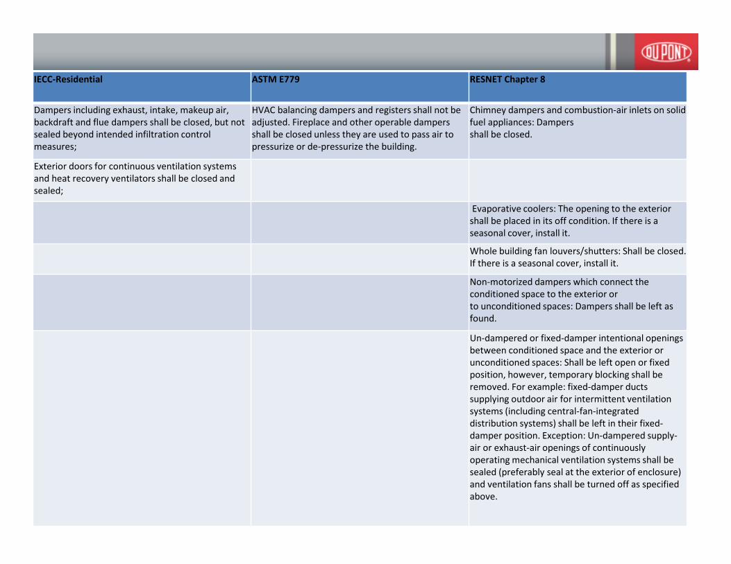
IECC-Residential ASTM E779 RESNET Chapter 8
Dampers including exhaust, intake, makeup air,
backdraft and flue dampers shall be closed, but not
sealed beyond intended infiltration control
measures;
HVAC balancing dampers and registers shall not be
adjusted. Fireplace and other operable dampers
shall be closed unless they are used to pass air to
pressurize or de-pressurize the building.
Chimney dampers and combustion-air inlets on solid
fuel appliances: Dampers
shall be closed.
Exterior doors for continuous ventilation systems
and heat recovery ventilators shall be closed and
sealed;
Evaporative coolers: The opening to the exterior
shall be placed in its off condition. If there is a
seasonal cover, install it.
Whole building fan louvers/shutters: Shall be closed.
If there is a seasonal cover, install it.
Non-motorized dampers which connect the
conditioned space to the exterior or
to unconditioned spaces: Dampers shall be left as
found.
Un-dampered or fixed-damper intentional openings
between conditioned space and the exterior or
unconditioned spaces: Shall be left open or fixed
position, however, temporary blocking shall be
removed. For example: fixed-damper ducts
supplying outdoor air for intermittent ventilation
systems (including central-fan-integrated
distribution systems) shall be left in their fixed-
damper position. Exception: Un-dampered supply-
air or exhaust-air openings of continuously
operating mechanical ventilation systems shall be
sealed (preferably seal at the exterior of enclosure)
and ventilation fans shall be turned off as specified
above.

IECC-Residential ASTM E779 RESNET Chapter 8
Heating and cooling systems, if installed at the time
of the test, shall be turned off; and
Combustion appliances: Shall remain off during the
test.
Combustion appliance flue gas vents: Shall be left in
their normal appliance-off condition.
Fans: Any fan or appliance capable of inducing
airflow across the building enclosure shall be turned
off including, but not limited to, clothes dryers, attic
fans, kitchen and bathroom exhaust fans, outdoor
air ventilation fans, air handlers, and crawl space
and attic ventilation fans. Continuously operating
ventilation systems shall be turned off and the air
openings sealed, preferably at the exterior
terminations.
Supply and return registers, if installed at the time of
the test, shall be fully open
Supply registers and return grilles: Shall be left open
and uncovered.
Plumbing drains with p-traps: Shall be sealed or filled
with water, if empty
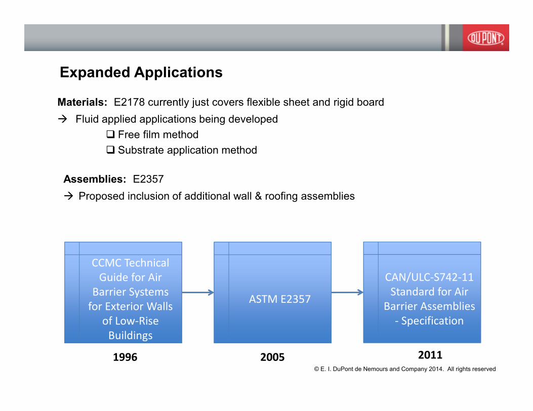
Expanded Applications
Materials: E2178 currently just covers flexible sheet and rigid board
� Fluid applied applications being developed
� Free film method
� Substrate application method
Assemblies: E2357
� Proposed inclusion of additional wall & roofing assemblies
CCMC Technical
Guide for Air
Barrier Systems
for Exterior Walls
of Low-Rise
Buildings
1996
ASTM E2357
2005
CAN/ULC-S742-11
Standard for Air
Barrier Assemblies
- Specification
2011© E. I. DuPont de Nemours and Company 2014. All rights reserved
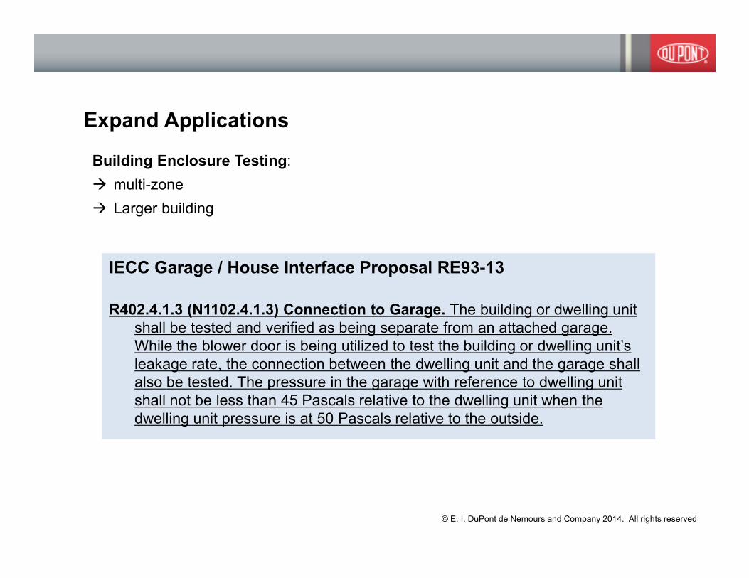
Expand Applications
Building Enclosure Testing:
� multi-zone
� Larger building
IECC Garage / House Interface Proposal RE93-13
R402.4.1.3 (N1102.4.1.3) Connection to Garage. The building or dwelling unit
shall be tested and verified as being separate from an attached garage.
While the blower door is being utilized to test the building or dwelling unit’s
leakage rate, the connection between the dwelling unit and the garage shall
also be tested. The pressure in the garage with reference to dwelling unit
shall not be less than 45 Pascals relative to the dwelling unit when the
dwelling unit pressure is at 50 Pascals relative to the outside.
© E. I. DuPont de Nemours and Company 2014. All rights reserved
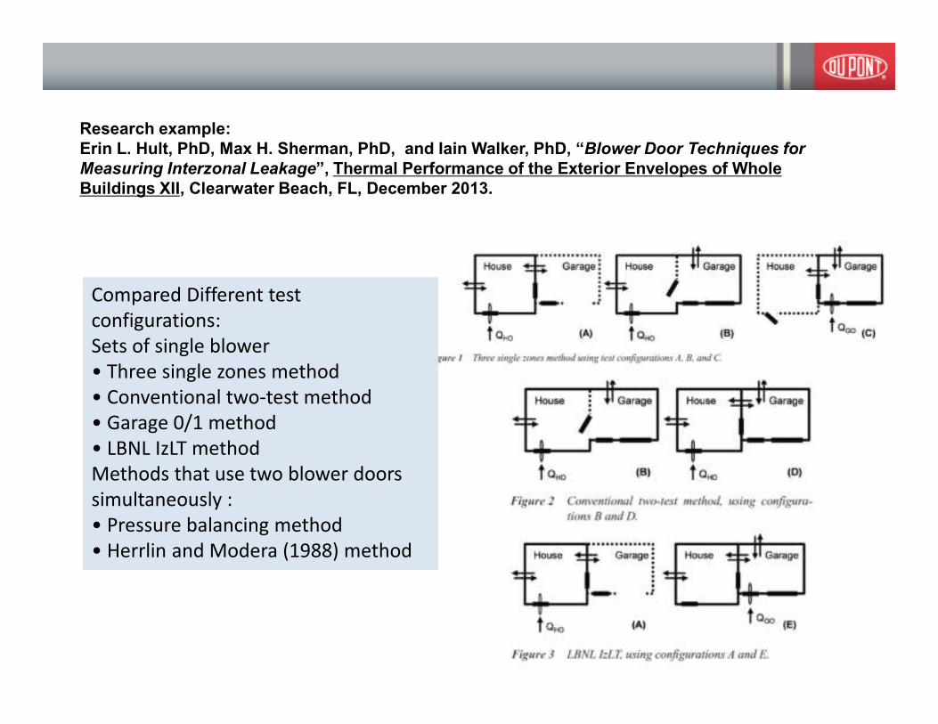
Research example:
Erin L. Hult, PhD, Max H. Sherman, PhD, and Iain Walker, PhD, “Blower Door Techniques for
Measuring Interzonal Leakage”, Thermal Performance of the Exterior Envelopes of Whole
Buildings XII, Clearwater Beach, FL, December 2013.
Compared Different test
configurations:
Sets of single blower
• Three single zones method
• Conventional two-test method
• Garage 0/1 method
• LBNL IzLT method
Methods that use two blower doors
simultaneously :
• Pressure balancing method
• Herrlin and Modera (1988) method

Decision Tree for Hult, et. al. “Blower Door Techniques for Measuring Interzonal Leakage”,
Thermal Performance of the Exterior Envelopes of Whole Buildings XII, Clearwater Beach, FL,
December 2013.

Research example:
Terry Brennan, Wagdy Anis, Gary Nelson, and Collin Olson, PhD , “ASHRAE 1478: Measuring
Airtightness of Mid- and High-Rise Non-Residential Buildings” Thermal Performance of the
Exterior Envelopes of Whole Buildings XII, Clearwater Beach, FL, December 2013.
� ASHRAE 1478 is a research project designed
to measure enclosure airtightness of mid-
and high-rise buildings in the United States.
� Data were collected from 16 non-residential
buildings in climate zones 2–7 constructed
since the year 2000.
� A fan pressure testing protocol based on
ASTM E779 was developed by the project
team.
� A number of issues in using E779 to test
large building were identified, discussed,
and addressed.

Support Compliance
� Build on industry experience & research
� New Standards Development
� “Interlaboratory” Studies to determine precision & bias
© E. I. DuPont de Nemours and Company 2014. All rights reserved

LBNL Data Base
http://resdb.lbl.gov/

Research example:
Wanyu R. Chan, PhD. And Max H. Sherman, PhD, “Building Envelope and Duct Airtightness
of New US Dwellings”, Thermal Performance of the Exterior Envelopes of Whole Buildings XII,
Clearwater Beach, FL, December 2013.
� Analyzed the building envelope and duct system airtightness of US single-family
detached homes built since 2000 (Lawrence Berkeley National Laboratory
Residential Diagnostics Database (ResDB)).
• 26,000 building envelope and 11,000 duct system air leakage data.
� The majority of US homes built in the past ten years meet IECC 2009.
� About 80% met the IECC building envelope airtightness guideline of 7
ACH50.
� Over 90% of the homes met the IECC 2009 duct system airtightness
guideline of 12 cfm25.
� Fewer homes are meet the 2012 levels,
� Only30%of the homes met IECC 2012 building envelope airtightness of
5ACH50 in climate zones 1 and 2, and 10% meeting 3 ACH50 in climate
zones 3–8.
� Slightly over half of the US homes in ResDB are meeting the IECC 2012
duct system airtightness guideline of 4 cfm25..
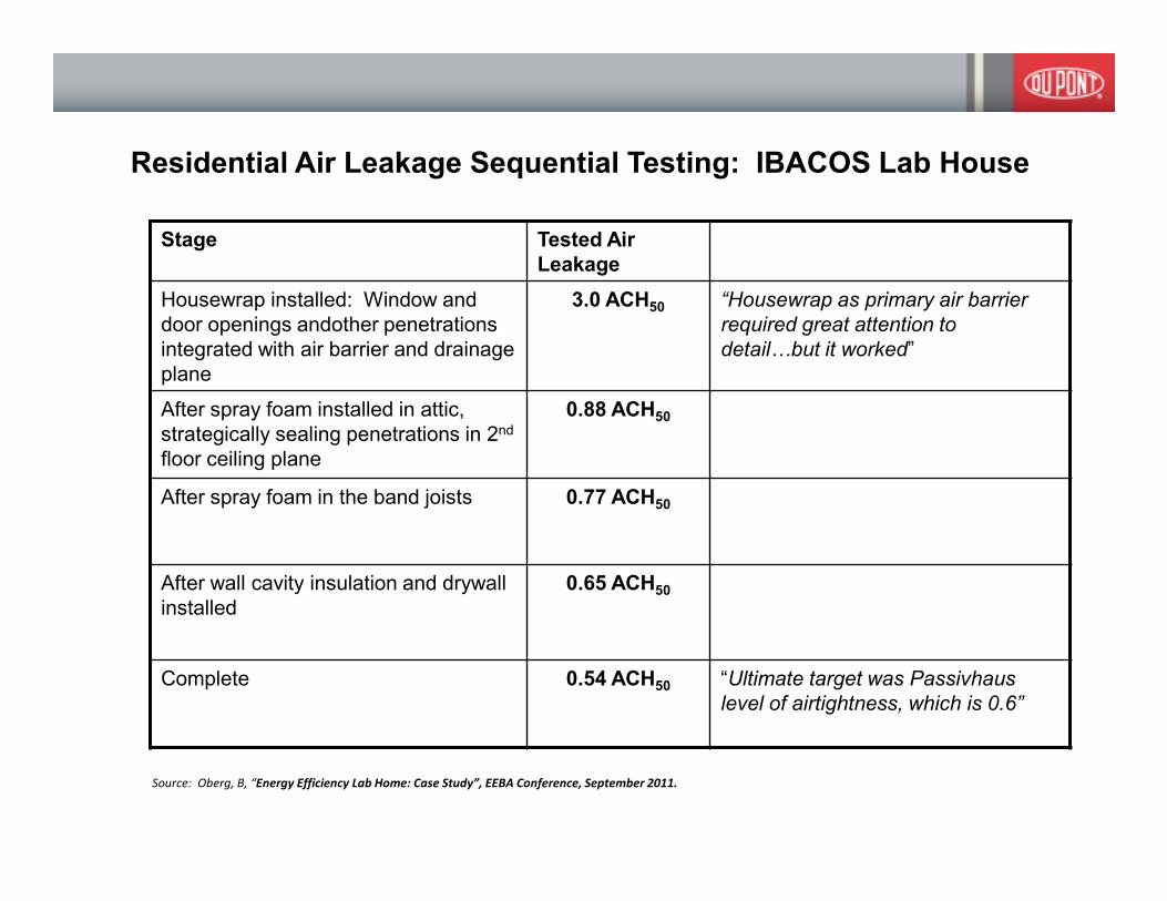
Residential Air Leakage Sequential Testing: IBACOS Lab House
Stage Tested Air
Leakage
Housewrap installed: Window and
door openings andother penetrations
integrated with air barrier and drainage
plane
3.0 ACH50 “Housewrap as primary air barrier
required great attention to
detail@but it worked”
After spray foam installed in attic,
strategically sealing penetrations in 2nd
floor ceiling plane
0.88 ACH50
After spray foam in the band joists 0.77 ACH50
After wall cavity insulation and drywall
installed
0.65 ACH50
Complete 0.54 ACH50 “Ultimate target was Passivhaus
level of airtightness, which is 0.6”
Source: Oberg, B, “Energy Efficiency Lab Home: Case Study”, EEBA Conference, September 2011.
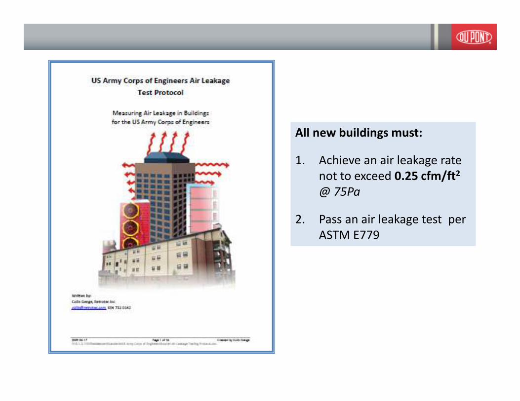
All new buildings must:
1. Achieve an air leakage rate
not to exceed 0.25 cfm/ft2
@ 75Pa
2. Pass an air leakage test per
ASTM E779

© E. I. DuPont de Nemours and Company 2014. All rights reserved

© E. I. DuPont de Nemours and Company 2014. All rights reserved

© E. I. DuPont de Nemours and Company 2014. All rights reserved
© E. I. DuPont de Nemours and Company 2014. All rights reserved
© E. I. DuPont de Nemours and Company 2014. All rights reserved

© E. I. DuPont de Nemours and Company 2014. All rights reserved

Implementing USACE Air tightness Requirements:
A General Contractor’s Perspective
Follow the details – know what items are part of the continuous air
barrier; attention to detail is critical in design and construction
Materials compatibility – make sure the materials specified are
compatible
Manufacturers’ installation instruction – engage manufacturers’
representatives for training, site visits, inspections
Verify & document – make sure that the details are being followed.
Sealing the envelope is cheap during construction but more
expensive afterwards (cost 10 to 1000X more afterwards).
Source: Hensel Phelps Construction Co.

0.0
5
0.0
6
0.0
7
0.0
7
0.0
7
0.0
8
0.1
0.1
0.1
0.1
1
0.1
3
0.1
4
0.1
4
0.1
5
0.1
5
0.1
5
0.1
5
0.1
5
0.1
5
0.1
6
0.1
6
0.1
7
0.1
7
0.1
9
0.1
9
0.2
0.2
1
0.2
2
0.2
2
0.2
2
0.2
2
0.2
5
0
0.05
0.1
0.15
0.2
0.25
0.3
0 5 10 15 20 25 30 35
Air leakage rate [cfm/ft2 @0.3 in w.c. (75Pa)
USACE Standard Experience
Source: Dr. Alexander Zhivov, USACE ERDC, Champaign, USA: AIVC Workshop, June 14, 2010, Brussels, Belgium
Current USACE Standard (0.25 cfm/ft2 @ 75Pa )
Up to 80% more airtight than current USACE Standard
Future USACE Standard:
(0.15 cfm/ft2 @ 75Pa )
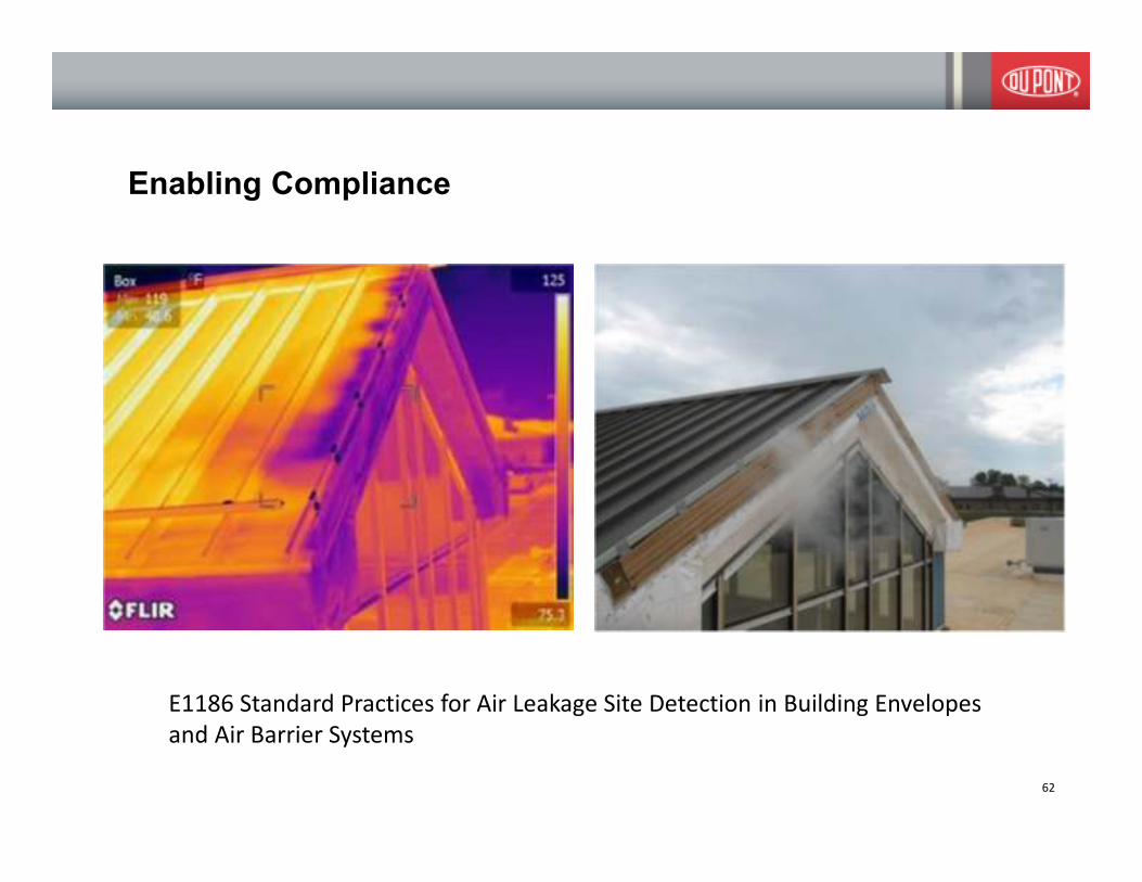
Enabling Compliance
62
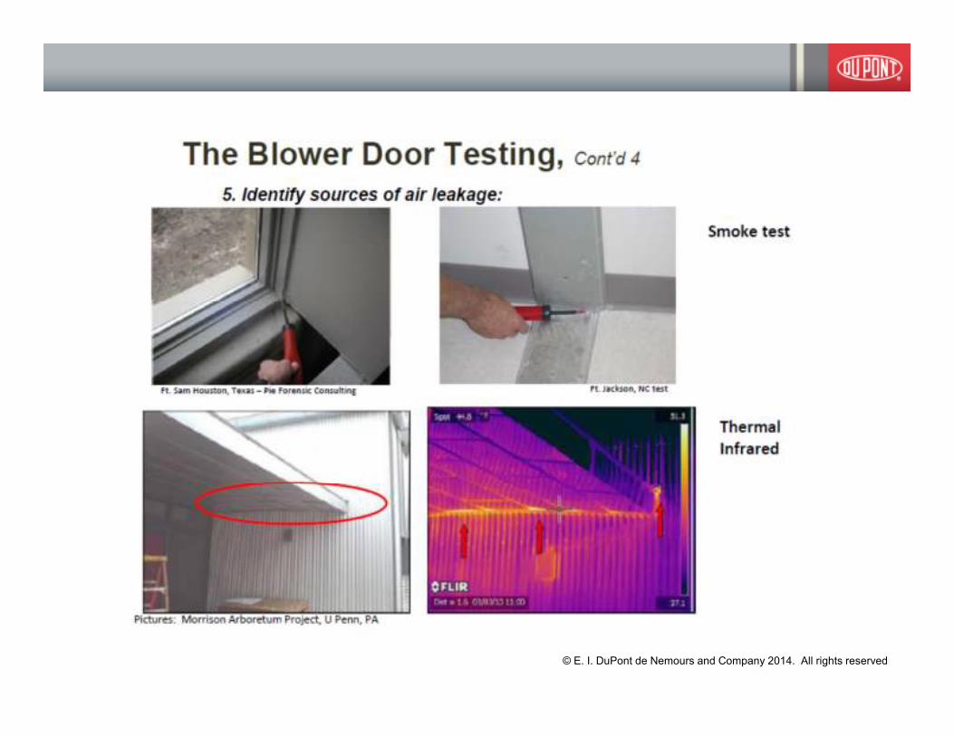
Photos courtesy Pie Forensic Consultants
E1186 Standard Practices for Air Leakage Site Detection in Building Envelopes
and Air Barrier Systems

New Standard Test Method by ABAA & ASTM E06.41: Standard
Method for Building Enclosure Air Tightness Compliance Testing
Draft Scope
� This standard test method provides a quantitative field-test procedure and
calculation method for assessing compliance of a building enclosure with an air
tightness specification using fan- induced pressure differences.
� Building setup conditions appropriate for testing the enclosure’s air tightness
are defined in this standard.
� Guidelines to identify the air barrier boundaries of the building enclosure to be
tested are provided in this standard.
� This test method applies to all building types and portions thereof.
� This test method is applicable to typical indoor-outdoor temperature
differentials and low to moderate wind pressure conditions.
� This standard defines two test procedures: multipoint regression and repeated
single point pressure testing.
� This standard allows for testing compliance with pressurization only,
depressurization only or a combination.
63

ASTM Workshop on Whole-Building Airtightness Testing,
October 2012, Atlanta GA.
� Terry Brennan / Collin Olson: Building Airtightness Testing Overview
� Phil Emory: Case Studies Using ASTM E1827 to Pressure-Test Whole
Buildings
� Colin Genge: Case studies of air leakage tests on large, complex
buildings.
� Max Sherman: Variations in Residential Air Leakage Measurements
� Steven Emmerich: Update on U.S. Commercial Building Airtightness –
Data and Standards Issues
� Wagdy Anis: Reality Check: Actual Air Leakage Rates in Buildings
� Kevin Knight : Building Enclosure Commissioning

ASTM Inter-laboratory studies (Jan 10, 2012 email)
Dear Theresa,
ASTM's Interlaboratory Study Program would like to lend you a hand! According to our records, we see that ASTM WK35913@needs Repeatability and Reproducibility cited in the precision and bias section.
ASTM's Form and Style Manual requires test methods contain a statement (1) regarding within-laboratory precision of the test results (repeatability) when approved, and (2) regarding the precision of test results obtained in different laboratories (reproducibility) within 5 years. @
Precision and bias statements validate the methodology of your standard, and greatly benefit the user. The ILS Program is designed to support the committees in their efforts to produce precision statements for their test methods and is available to assist in the following areas:
• Designing an interlaboratory study
• Identifying potential samples
• Soliciting volunteer laboratories
• Finding available suppliers
• Contracting with distributors
• Reviewing laboratory instructions
• Collecting and analyzing data
• Producing a draft precision statement
• Compiling information for the research report
• Giving recognition to participating laboratories
65© E. I. DuPont de Nemours and Company 2014. All rights reserved

Type of Test Test Result P&B Statement
E283 Standard Test Method for Determining Rate of
Air Leakage Through Exterior Windows, Curtain
Walls, and Doors Under Specified Pressure
Differences Across the Specimen
Lab Assembly Curve of air leakage vs.
pressure
The precision and bias of this test method has not been
determined.
E2178 Standard Test Method for Air Permeance of
Building Materials
Product Performance Air Leakage @75 Pa
Curve of air leakage vs.
pressure
The precision and bias of the test method have not been
determined
E2357 Standard Test Method for Determining Air
Leakage of Air Barrier Assemblies
Specified lab assembly
subjected to specified
proconditioning.
Air Leakage @75 Pa
Curve of air leakage vs.
pressure
The precision and bias of this practice has not been determined.
The precision and bias of the individual test procedures required
are given in those methods.
E330 Standard Test Method for Structural
Performance of Exterior Windows, Doors,
Skylights and Curtain Walls by Uniform Static
Air Pressure
Difference
Lab Assembly pass/fail at specified or max
pressure
No statement is made either on the precision or bias of this test
method for measuring structural performance, since this method
merely states whether or not the test specimen sustained the
loads applied and otherwise conformed to the criteria specified for
success.
E331 Standard Test Method for Water Penetration of
Exterior Windows, Skylights, Doors, and Curtain
Walls by Uniform Static Air Pressure
Difference
Lab Assembly pass/fail at specified or max
pressure
No statement is made either on the precision or bias of this test
method for measuring water penetration since the result merely
states whether there is conformance to the criteria specified for
success.
E779 Standard Test Method for Determining Air
Leakage Rate by Fan Pressurization1
Whole Building Multi-point Air Leakage under
infiltration and exfiltration
conditions
The confidence limits calculated in 9.7 give an estimate of the
precision uncertainty of the test results. The specific precision and
bias of this test method is dependent largely on the
instrumentation and apparatus used and on the ambient
conditions under which the data are taken.
E1827 Standard Test Methods for
Determining Airtightness of Buildings Using an
Orifice
Blower Door1
Whole Building Air Leakage under infiltration
and exfiltration conditions
11.1 Measurement Uncertainty—The precision and bias of this
standard depend on the instrumentation and apparatus used, the
test zone envelope, and the ambient conditions under which the
data are taken.6 Refer to recommended maximum values for
precision and bias in Tables X1.1 and X1.2. These
recommendations achieve the following uncertainties when
calculated in accordance with Annex A3.
11.2 Single-Point Method—The uncertainty of measured flow at 50
Pa is 10 % using the single-point measurement
assumptions for precision and bias and 5 % using the two-point
assumptions.
11.3 Two-Point Method—Assuming an exponent of n = 0.65, P1 =
50 Pa (0.2 in. H2O), and P2 = 12.5 Pa (0.05 in.
H2O), the uncertainty of extrapolating to measured flow at 4 Pa
(0.016 in. H2O) would be 13 % using the two-point assumptions
for precision and bias. Estimates of C and n have uncertainties of
10 % and 0.05, respectively, for the two-point assumptions.66

Many enclosure air leakage test method
standards date back to the mid 1980’s
With the recent code evolution is creating the
need to update the standards with a focus on
compliance.
Change will not be made by a single person – we
need to work together.
Opportunities:
� Communication with and training of building
officials
� Participate in Codes and Standard
development
� Participation in Interlaboratory studies, and
other research to understand repeatability
and reproduceability of test methods
67
© E. I. DuPont de Nemours and Company 2014. All rights reserved
Thank You
The DuPont Oval Logo, DuPont™ and The miracles of science™ are registered trademarks or trademarks of DuPont or its affiliates.
© 2014 All Rights Reserved