encoding and modulation techniques -...
TRANSCRIPT

2/45
Encoding and Modulation TechniquesEncoding and Modulation Techniques
3/45
Digital Signaling Versus Analog SignalingDigital Signaling Versus Analog Signaling
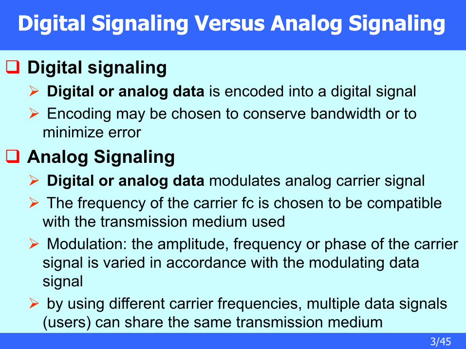
Digital signaling
Digital or analog data is encoded into a digital signal
Encoding may be chosen to conserve bandwidth or to
minimize error
Analog Signaling
Digital or analog data modulates analog carrier signal
The frequency of the carrier fc is chosen to be compatible
with the transmission medium used
Modulation: the amplitude, frequency or phase of the carrier
signal is varied in accordance with the modulating data
signal
by using different carrier frequencies, multiple data signals
(users) can share the same transmission medium
4/45
Digital SignalingDigital Signaling
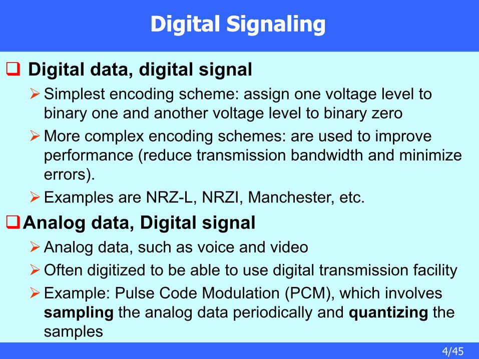
Digital data, digital signal
Simplest encoding scheme: assign one voltage level to
binary one and another voltage level to binary zero
More complex encoding schemes: are used to improve
performance (reduce transmission bandwidth and minimize
errors).
Examples are NRZ-L, NRZI, Manchester, etc.
Analog data, Digital signal
Analog data, such as voice and video
Often digitized to be able to use digital transmission facility
Example: Pulse Code Modulation (PCM), which involves
sampling the analog data periodically and quantizing the
samples

5/45
Analog SignalingAnalog Signaling
Digital data, Analog Signal
A modem converts digital data to an analog signal so that it
can be transmitted over an analog line
The digital data modulates the amplitude, frequency, or
phase of a carrier analog signal
Examples: Amplitude Shift Keying (ASK), Frequency Shift
Keying (FSK), Phase Shift Keying (PSK)
Analog data, Analog Signal
Analog data, such as voice and video modulate the
amplitude, frequency, or phase of a carrier signal to produce
an analog signal in a different frequency band
Examples: Amplitude Modulation (AM), Frequency
Modulation (FM), Phase Modulation (PM)

6/45
Digital Data, Digital SignalDigital Data, Digital Signal
Digital signal
discrete, discontinuous voltage pulses
each pulse is a signal element
binary data encoded into signal elements
Periodic signalsPeriodic signals
7/45
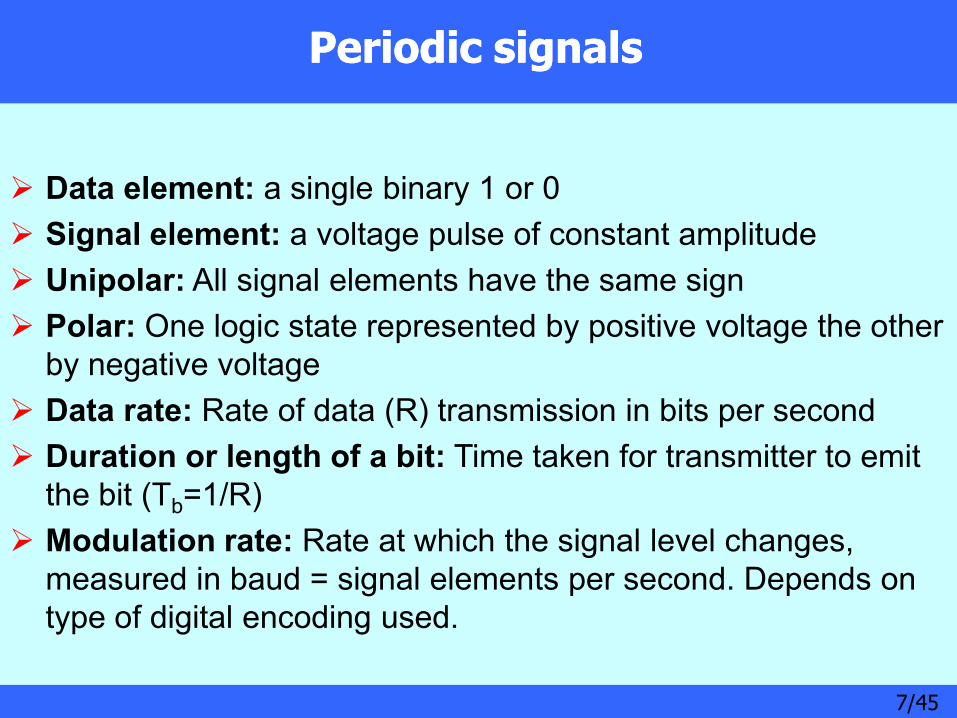
Data element: a single binary 1 or 0
Signal element: a voltage pulse of constant amplitude
Unipolar: All signal elements have the same sign
Polar: One logic state represented by positive voltage the other
by negative voltage
Data rate: Rate of data (R) transmission in bits per second
Duration or length of a bit: Time taken for transmitter to emit
the bit (Tb=1/R)
Modulation rate: Rate at which the signal level changes,
measured in baud = signal elements per second. Depends on
type of digital encoding used.

8/45
Interpreting SignalsInterpreting Signals
Need to know
timing of bits: when they start and end
signal levels: high or low
factors affecting signal interpretation
Data rate: increase data rate increases Bit Error Rate (BER)
Signal to Noise Ratio (SNR): increase SNR decrease BER
Bandwidth: increase bandwidth increase data rate
encoding scheme: mapping from data bits to signal elements

9/45
Comparison of Encoding Schemes
signal spectrum
Lack of high frequencies reduces required bandwidth,
lack of dc component allows ac coupling via transformer,
providing isolation,
should concentrate power in the middle of the bandwidth
Clocking
synchronizing transmitter and receiver with a sync
mechanism based on suitable encoding
error detection
useful if can be built in to signal encoding
signal interference and noise immunity
cost and complexity: increases when increases data rate

10/45
Encoding Schemes
Positive level (+5V)
Negative level (-5V)
Positive level (+5V)
No line signal (0V)
Negative level (-5V)
11/45
Encoding Schemes
12/45
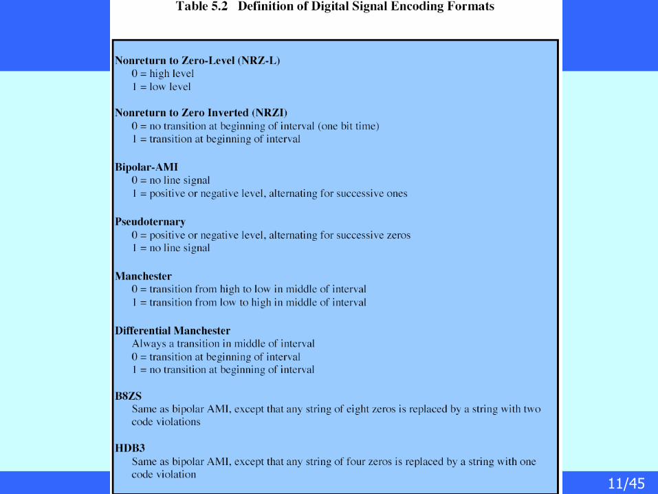
NonReturn to Zero-Level (NRZ-L)
Two different voltages for 0 and 1 bits
Voltage constant during bit interval
no transition, i.e. no return to zero voltage
more often, negative voltage for binary one
and positive voltage for binary zero
13/45
NonReturn to Zero INVERTED (NRZI)
Nonreturn to zero inverted on ones
Constant voltage pulse for duration of bit
Data encoded as presence or absence of signal transition at beginning of bit time transition (low to high or high to low) denotes binary 1
no transition denotes binary 0
Example of differential encoding since have – data represented by changes rather than levels
– more reliable detection of transition rather than level
14/45
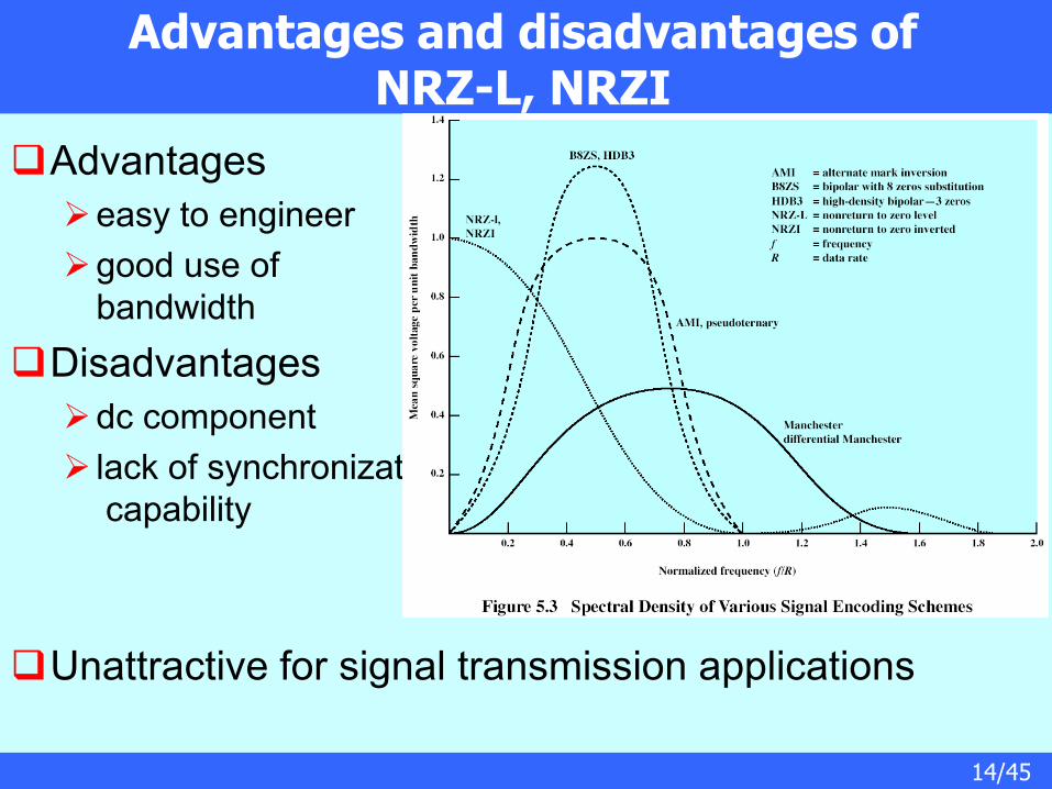
Advantages and disadvantages of NRZ-L, NRZI
Advantages
easy to engineer
good use of
bandwidth
Disadvantages
dc component
lack of synchronization
capability
Unattractive for signal transmission applications
15/45
Multilevel Binary Bipolar Alternate Mark Inversion (AMI)
Use more than two levels (three levels, positive, negative and no line signal)
Bipolar-AMI
zero represented by no line signal
one represented by positive or negative pulse
one pulses alternate in polarity
no loss of sync if a long string of ones
long runs of zeros still a problem
no net dc component
lower bandwidth
easy error detection
45/45
QAM Variants
Two level ASK (two different amplitude levels)
each of two streams in one of two states
four state system
essentially QPSK
Four level ASK (four different amplitude levels)
combined stream in one of 16 states
Have 64 and 256 state systems
Improved data rate for given bandwidth
but increased potential error rate