encore door controller reference manual
TRANSCRIPT
Encore DOOR CONTROLLER REFERENCE MANUAL
REV P
Encore PWM Door Controller Reference Manual Page 1

Table of Contents Table of Contents.............................................................................................................. 2 Warnings and Precautions................................................................................................ 3 Definitions of Terms .......................................................................................................... 4 Software Compatibility ...................................................................................................... 4 Installation Overview......................................................................................................... 5 Encore Installation ............................................................................................................ 7 Initial Adjustment and Learning....................................................................................... 15 Selectable Software Options........................................................................................... 20 Adjustment ...................................................................................................................... 21 Motor Field Operation ..................................................................................................... 26 Door Parameter Definitions............................................................................................. 26 Keyboard and Display Operation .................................................................................... 33 Fault Indications.............................................................................................................. 38 How Closed Loop Pulse Width Modulation Works.......................................................... 42 Electrical Specifications .................................................................................................. 43
Please call us at 815-759-3934 for technical assistance.
This document copyright 1999, 2000-2007 by IPC Automation, Inc. and Avanti Systems, Inc. all rights reserved. Reproduction or storage in any form is prohibited except as agreed in writing by IPC Automation, Inc. / Avanti Systems, Inc. Revision History Date Rev Description 07-APR-1999 A First published manual 11-JUL-1999 B Menu changes and new options 17-JUL-1999 C Changes to Gain Limits, Added ExIn setup, Added data on gain settings, Fields, Specifications 01-DEC-1999 D Revised manual for PCB version C 07-DEC-1999 E Encore changes from IPC 12-DEC-1999 F IPC Internal SP revisions 21-MAR-2000 G Added Stoptgt, cleaned Diff. Gain 02-MAY-2000 H Revised Learning procedure 24-JUL-2000 J Corrections and clarifications 15-NOV-2000 K Added description for display and obstruction. 18-DEC-2000 L Added Information on 130VDC and Single Input Operation 21-JAN-2001 M Corrections to connection figures. 09-SEP-2001 N 90Vac input/single input/parameter table/IPC motor 22-MAR-2002 O Added op stp trgt, adj creep speed, imprvd Close slow tq limit 23-OCT-2007 P Added Charts – many updates-quick start encoder colors-130VDC
Encore PWM Door Controller Reference Manual Page 2
Warnings and Precautions WARNING: This assembly operates with Dangerous Voltages which can result in serious injury or death. These voltages are present at all times the assembly has power applied. Dangerous voltages are present on the assembly for a period of up to one hour following removal of power. CAUTION: Never apply any capacitor to the output of this assembly. Destruction of the power devices is possible. Apply only inductive motor leads suitable for the application of 120VDC and up operating voltages. CAUTION: The output motor leads of this assembly are not at ground potential. Never ground any motor lead under any circumstances. Before application of power, verify the motor is isolated from ground by at least 10 Million ohms resistance. CAUTION: This assembly must always be operated within the supplied enclosure /heatsink panel since the enclosure provides heat dissipation for the power devices mounted to it.
DO NOT REMOVE THE PCB FROM THE SUPPLIED MOUNTING PANEL- DAMAGE TO THE SEMI-CONDUCTORS WILL OCCUR – PLEASE NOTE THAT IF THE PANEL IS REMOVED – THE WARRANTY WILL BE VOID. DO NOT DRILL OR PUNCH (GREENLEE) THE MOUNTING PANEL IN ANY WAY. DRILLING/PUNCHING WILL DAMAGE THE UNDER-BOARD SEMI-CONDUCTORS AND WILL ALSO VOID THE WARRANTY
Encore PWM Door Controller Reference Manual Page 3
Definitions of Terms The following terms are used in this documentation DOL - Door Opened Limit DCL - Door Closed Limit EPROM - Erasable Programmable Read Only Memory (program storage memory) LCD - Liquid Crystal Display PCB/PCBA - Printed Circuit Board or Printed Circuit Board Assembly PWM - Pulse Width Modulation, speed control means of motor Torque - Twisting force measured in Lb.-Ft
Software Compatibility For use of all the features described in this manual the software in the controller must be at Version 2.007.01 or later. Earlier software will not provide the Single signal door operating mode or the ability to stop the door at only the closed limit. The version number is displayed each time the power is applied to the controller.
Encore PWM Door Controller Reference Manual Page 4
Installation Overview This section provides a summary of the steps that will need to be performed when installing the Encore door controller. It does not replace the detailed information located in other sections of this manual. It lists the essential steps required for correct operation. Use this section as a checklist and read the detailed information for complete procedures and detailed information.
1. Refer to the Installation Electrical Drawing. This provides the answers to many hookup questions.
2. Insure that the 115VAC/130VDC power supply has adequate current and
proper wire size for loads of 15A. 3. Mount the motor/encoder as described in the separate installation documents.
4. Check your wiring and then apply power. The display should give the product
name and software version number 5. Install the limit switch mounting bracket (If applicable) and hardware and adjust
the electrical limits so they are active when the door is about ¼ inch from the mechanical stop. The limit switch operations are displayed as OL and CL in the Display Status menu
6. Set the display for Display Status by pressing INC then ENTER from the
main menu. This allows the input signals to be observed on the display. 7. Select a setup using QUICK SETUP for your particular door configuration. 8. Setups are available for center/side opening, single signal/dual signal inputs and
common door openings. If you do not find your operator listed, use any “GAL/Westinghouse” setup for a general starting point.
9. Learn the door opening via “Learn Counts” after the setup is selected. NOTE:
moving a limit or changing the width of the opening REQUIRES a new Learn process.
10. Use the car-top pushbuttons to determine and adjust the closing force setting
to the maximum allowed. 11. If desired and permitted by local your codes and regulations, change the
Obstruction method from ALWAYS to DETECT. (See page 17) 12. Adjust the Parameters (Variables) for smooth operation.
Encore PWM Door Controller Reference Manual Page 5
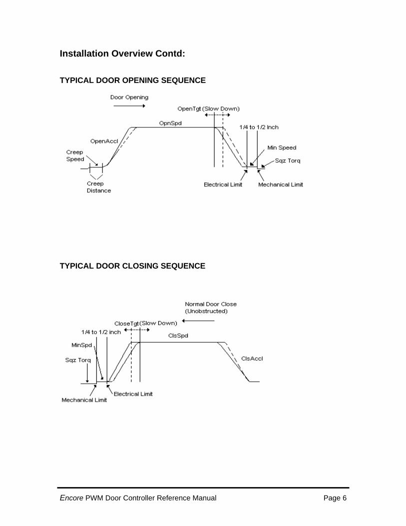
Installation Overview Contd: TYPICAL DOOR OPENING SEQUENCE
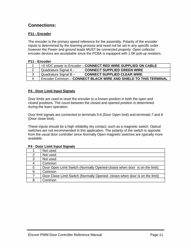
TYPICAL DOOR CLOSING SEQUENCE
Encore PWM Door Controller Reference Manual Page 6

OBSTRUCTED DOOR CLOSE SEQUENCE:
Encore Installation Mechanical installation will depend on the type of door operator that this assembly is applied to. The steps below are of a general nature and describe the common requirements for equipment mounting.
Encore Mechanical Installation Mechanical installation consists of three basic steps: 1. Mount the enclosure in a secure car-top location, which will not be subject to
excessive vibration. Vibration can cause long-term hardening of interconnecting wires leading to device failure.
2. Mount the motor/encoder assembly per the instructions for the specific controller
type. If an external/customer supplied encoder is used It is very important that the encoder accurately reflect motor shaft rotation with a minimum of backlash. Excessive backlash can lead to noisy/rough operation.
Encore PWM Door Controller Reference Manual Page 7

3. Mount the door electrical limits so that they indicate the limit position about ¼” to ½” prior to the actual mechanical limit. Dress all wires so they are clear of moving parts.
Door Mechanical Adjustment Little adjustment will be required if the above steps are taken. The precise location of the electrical limits versus the physical limits may need adjustment. These should be adjusted so that the door does not “bounce” out of the limit due to insufficient distance between electrical limit and the mechanical limit. At the other extreme, if the distance between electrical and physical limit is excessive then the door will stop normally but then pick up speed at the electrical limit and produce a jerky stop Reduce or eliminate any mechanical/fluid door checks so that the door closes and opens with minimum restriction. Mechanical checks can adversely affect the operation of the speed control program.
Mechanical Considerations The following should be considered for proper door operation. 1. Is there excessive play in the mechanical linkages to the doors? Excessive play will
cause jerky door operation. 2. If belts are used to operate the door are they in good condition? The high torque of
the operator may cause a work or weak belt to fail. 3. Are shaft bushings within service limits? Bushing wear can also produce jerky
operation or noise. 4. The door must operate without excessive friction or binding. Door friction or binding
will cause excessive motor currents, reducing motor life. Door operation should be smooth in both directions of travel.
5. If an external or customer supplied position encoder mounted correctly without run-
out or wobble? Improper installation can result in the encoder being destroyed or the drive belt being thrown or broken.
Electrical Installation. Electrical installation consists of connecting the signals to the PCBA as detailed in the CONNECTION SUMMARY of this manual and the hookup drawing on the last page of this manual. While this is straightforward the following tips should be used: 1. All wiring must be clear of any mechanical interference. 2. Input power must be 115 VAC or 130 VDC at 15Amps capability, consider voltage
drop over travel cable length. The Encore will operate at a lower torque with the use of 90 VAC or 130VDC that is provided on some controllers.
3. Keep limit wiring and encoder wiring away from AC power and DC motor leads.
Encore PWM Door Controller Reference Manual Page 8

Electrical Installation contd: 4. Input control power (120VAC-130VDC) must be maintained on at all times the
controller is active. It must not be cycled on each door operation or when the operating circuit is opened. An exception to this is operation with an existing relay controller (such as Otis) where the 130 VDC power is removed when the generator is not running.
5. The inputs for open, close, slow speed and extra (Safety Edge) require an external
power source. The standard limit power source may be either 115 VAC or 130 VDC. Polarity is not important. Other optional external supply voltages may be ordered. All input signals share a common signal that may be either polarity.
Important notes for P9 Limit outputs EX OUT, DCL and DOL The outputs from the Encore to the elevator controller for open limit, close limit and pre-closed limit are capable of operating with high voltages (up to 300 VDC) but at limited current rated to 100mA MAX. Exceeding the current maximum will cause P9 output device(s) failure. Do not connect or drive large relays or capacitive loads (RC timing circuits) to these outputs.
Encoder Installation- (Pre-assembled on the IPC Supplied PM Motor Assembly) The encoder is critical to the performance of the door operator. It is pre-mounted on the supplied motor and comes pre-wired with ~6 feet of 4 conductor shielded cable. If the encoder ever requires replacement the shield must NOT be connected on the motor end. The shield only connects on the controller end. • The encoder must be connected only to the encoder terminals of the Encore door
controller.
Encore PWM Door Controller Reference Manual Page 9

Controller Connection Summary All door controller connections must be made prior to the application of power to the assembly. P12 - Power and Load Connector Use only single-phase 115 VAC power. DO NOT use with 208 or 240VAC. Use of 130 VDC may be acceptable for existing relay controllers. Note that some Otis controllers can provide a DC supply of 130 VDC. Use of this power source is acceptable if the resulting torque on the door motor is sufficient to operate the door as desired. The resulting torque will be lower than if a 115VAC supply is used. Note that the door lock/unlock solenoid output is not used on this assembly. Do not connect anything to terminals 3 and 4 on terminal block “P12” Power is intended to always be applied to this assembly. Do not connect this assembly in a manner that will result in the loss of power unless power is removed from the complete elevator controller. The input power source must be capable of delivering 115VAC at 15 Amperes when measured at the door controller. Sufficiently large enough traveling cable conductors must be provided to meet this requirement. Refer to the caution at the top of this document regarding grounding and capacitive loads. The rated current of the armature is 6 Amps continuous, with 150% over-current permissible for up to 60 seconds. Lead polarity is not significant since the controller will determine the correct direction of rotation for proper operation during the learn operation. P12 Input and load connector:
1 Input Phase A 115 VAC input (Leg) or 130VDC voltage 2 Input Phase B 115 VAC input (Neutral) or 130VDC common 3 Not used
4 Not used
5 Motor Armature Output Lead (Do Not Ground) 6 Motor Armature Output Lead (Do Not Ground) 7 Not used (PM motor supplied with system)
8 Not used (PM motor supplied with system)
Encore PWM Door Controller Reference Manual Page 10
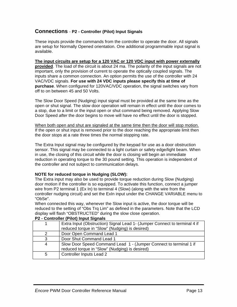
Connections: P11 - Encoder The encoder is the primary speed reference for the assembly. Polarity of the encoder inputs is determined by the learning process and need not be set in any specific order however the Power and ground leads MUST be connected properly. Open collector encoder devices are acceptable since the PCBA is equipped with 1.0K pull-up resistors. P11 - Encoder
1 +5 VDC power to Encoder – CONNECT RED WIRE SUPPLIED ON CABLE 2 Quadrature Signal A - CONNECT SUPPLIED GREEN WIRE 3 Quadrature Signal B – CONNECT SUPPLIED CLEAR WIRE 4 Encoder Common – CONNECT BLACK WIRE AND SHIELD TO THIS TERMINAL
P4 - Door Limit Input Signals Door limits are used to reset the encoder to a known position in both the open and closed positions. The count between the closed and opened position is determined during the learn operation. Door limit signals are connected to terminals 5-6 (Door Open limit) and terminals 7 and 8 (Door close limit). These inputs should be a high reliability dry contact, such as a magnetic switch. Optical switches are not recommended in this application. The polarity of the switch is opposite from the usual door controller since Normally Open magnetic switches are typically more available. P4 - Door Limit Input Signals
1 Not used 2 Not used 3 Not used 4 Common 5 Door Open Limit Switch (Normally Opened-closes when door is on the limit) 6 Common 7 Door Close Limit Switch (Normally Opened- closes when door is on the limit) 8 Common
Encore PWM Door Controller Reference Manual Page 11

Connections - P9 - Output Signals These provide the door limit signals to the system controller in a normal (Normally Closed) orientation. Note that for some relay controllers it may not be necessary to connect the door limit outputs since the controller has no means of using these signals. This will depend upon the requirements of the existing control equipment. One additional programmable output signal is available for a running signal or for a pre-closed signal. The function of the programmable output is selected using the keys on the assembly under the “change variable” “ExOut” menu selection. The output semi-conductors used at P9 outputs are rated at 300VAC or VDC at a maximum of 100ma.The outputs are essentially independent dry contacts with no common connections (see note below). P9- Output signals to elevator controller
1 Door Open Limit Output Lead 1 (Normally Closed) 2 Door Open Limit Output Lead 2 (Normally Closed) 3 Door Close Limit Output Lead 1 (Normally Closed) 4 Door Close Limit Output Lead 2 (Normally Closed) 5 Programmable Output Lead 1 (Pre DCL NC, Pre DCL NO or Running NO) 6 Programmable Output Lead 2 (Pre DCL NC, Pre DCL NO or Running NO)
The outputs from the Encore to the elevator controller for open limit, close limit and pre-closed limit are capable of operating with high voltages (up to 300 VDC) but at limited current rated to 100mA MAX!! Exceeding the current limit will cause output device failure. Do not connect large relays or capacitive loads (RC timing circuits) to these outputs. As of software version 2.004.00 the Programmable Output may be use for the following purposes: 1. RUNNING – Signal is closed any time the door is producing any torque (including
squeezing). 2. PDCL – Pre Door Closed Limit, opens whenever the door is within the PDCL
distance of the DCL position. This signal is determined by the encoder only. Loss of encoder will result in a loss of the PDCL signal. There is also a inverted Pre DCL signal available which is selected by the change variable, EX Out Menu selection.
3. CODE – Code Distance, Is enabled when the door is in the “code” distance used for
measuring the door closing energy. For a side-opening door the signal is active when the door is more than 2” (50mm) from either limit. For center opening doors the signal is active when the door is more than 1” (25mm) from either limits.
Encore PWM Door Controller Reference Manual Page 12
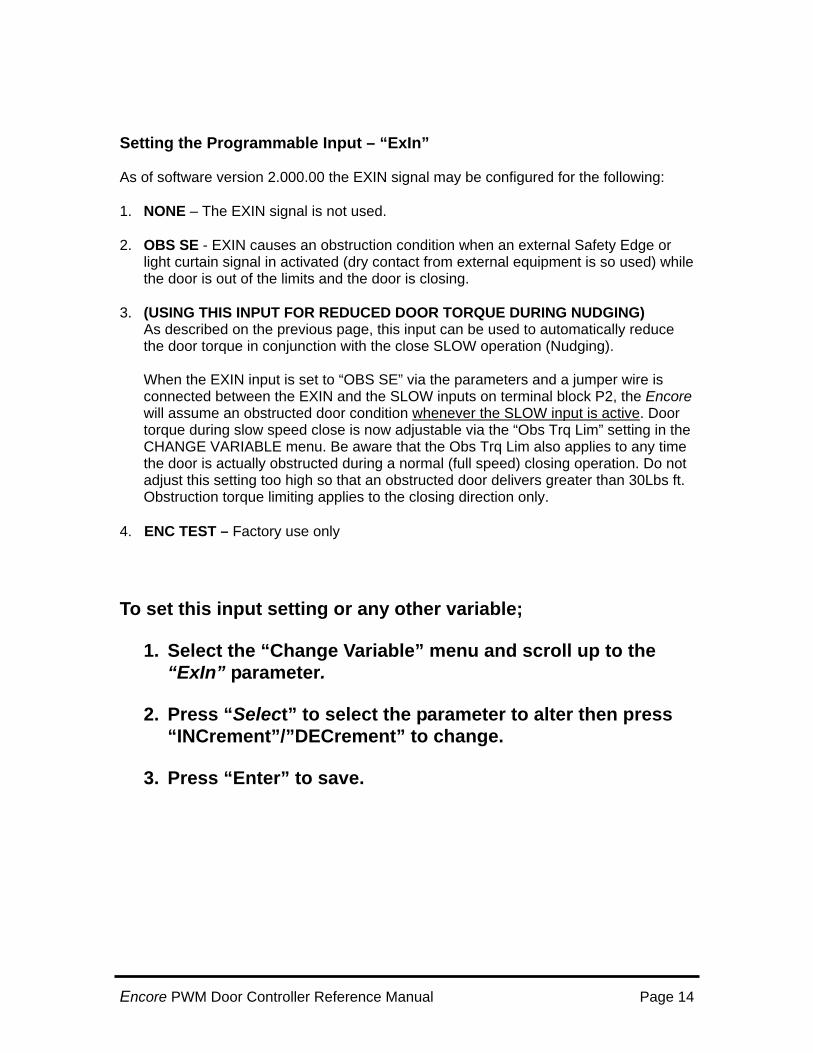
Connections - P2 - Controller (Pilot) Input Signals These inputs provide the commands from the controller to operate the door. All signals are setup for Normally Opened orientation. One additional programmable input signal is available. The input circuits are setup for a 120 VAC or 120 VDC input with power externally provided. The load of the circuit is about 24 ma. The polarity of the input signals are not important, only the provision of current to operate the optically coupled signals. The inputs share a common connection. An option permits the use of the controller with 24 VAC/VDC signals. For use with 24 VDC inputs please specify this at time of purchase. When configured for 120VAC/VDC operation, the signal switches vary from off to on between 45 and 50 Volts. The Slow Door Speed (Nudging) input signal must be provided at the same time as the open or shut signal. The slow door operation will remain in effect until the door comes to a stop, due to a limit or the input open or shut command being removed. Applying Slow Door Speed after the door begins to move will have no effect until the door is stopped. When both open and shut are signaled at the same time then the door will stop motion. If the open or shut input is removed prior to the door reaching the appropriate limit then the door stops at a rate three times the normal stopping rate. The Extra Input signal may be configured by the keypad for use as a door obstruction sensor. This signal may be connected to a light curtain or safety edge/light beam. When in use, the closing of this circuit while the door is closing will begin an immediate reduction in operating torque to the 30 pound setting. This operation is independent of the controller and not subject to communication delays. NOTE for reduced torque in Nudging (SLOW): The Extra input may also be used to provide torque reduction during Slow (Nudging) door motion if the controller is so equipped. To activate this function, connect a jumper wire from P2 terminal 1 (Ex In) to terminal 4 (Slow) (along with the wire from the controller nudging circuit) and set the ExIn input under the CHANGE VARIABLE menu to “ObSe”. When connected this way, whenever the Slow input is active, the door torque will be reduced to the setting of “Obs Trq Lim” as defined in the parameters. Note that the LCD display will flash “OBSTRUCTED” during the slow close operation. P2 - Controller (Pilot) Input Signals
1 Extra Input (Obstruction) Signal Lead 1- (Jumper Connect to terminal 4 if reduced torque in “Slow” (Nudging) is desired)
2 Door Open Command Lead 1 3 Door Shut Command Lead 1 4 Slow Door Speed Command Lead 1 - (Jumper Connect to terminal 1 if
reduced torque in “Slow” (Nudging) is desired) 5 Controller Inputs Lead 2
Encore PWM Door Controller Reference Manual Page 13
Setting the Programmable Input – “ExIn” As of software version 2.000.00 the EXIN signal may be configured for the following: 1. NONE – The EXIN signal is not used. 2. OBS SE - EXIN causes an obstruction condition when an external Safety Edge or
light curtain signal in activated (dry contact from external equipment is so used) while the door is out of the limits and the door is closing.
3. (USING THIS INPUT FOR REDUCED DOOR TORQUE DURING NUDGING)
As described on the previous page, this input can be used to automatically reduce the door torque in conjunction with the close SLOW operation (Nudging). When the EXIN input is set to “OBS SE” via the parameters and a jumper wire is connected between the EXIN and the SLOW inputs on terminal block P2, the Encore will assume an obstructed door condition whenever the SLOW input is active. Door torque during slow speed close is now adjustable via the “Obs Trq Lim” setting in the CHANGE VARIABLE menu. Be aware that the Obs Trq Lim also applies to any time the door is actually obstructed during a normal (full speed) closing operation. Do not adjust this setting too high so that an obstructed door delivers greater than 30Lbs ft. Obstruction torque limiting applies to the closing direction only.
4. ENC TEST – Factory use only
To set this input setting or any other variable;
1. Select the “Change Variable” menu and scroll up to the “ExIn” parameter.
2. Press “Select” to select the parameter to alter then press “INCrement”/”DECrement” to change.
3. Press “Enter” to save.
Encore PWM Door Controller Reference Manual Page 14

Initial Adjustment and Learning
Tests Prior to Applying Power Prior to powering up the Encore door controller, verify the following:
1. All connections are made per the CONNECTION SUMMARY (see last page of this manual).
2. Input power is 115 VAC, 15A. (Some Otis relay installations may provide 130VDC)
3. The door is able to move freely over the entire mechanical travel. 4. Oil checks are opened to prevent excess closing torque when approaching
the limits. 5. The motor leads are not grounded. 6. The door electrical limits are set as directed in the prior section.
Determine the following information that will be used in the adjustment procedure. The total door weight of ALL DOORS is used to determine the closing energy of the doors per the ANSI 17.1 and CSA B44 codes. Failure to enter the weights will produce incorrect closing energy reported values and possibly lead to excessive closing energies if misadjusted. Door opening span in inches _________ (Jot down opening for reference) Center or Side opening doors _________ (Jot down type for reference) Approximate weight of all door panels (total) in Lb. Or Kg.__________ (Jot down type for reference) (Please see note(s) above)
Step by Step Startup 1. Remove all open and close commands provided by the controller. Set the controller RUN/TEST switch to TEST. 2. Apply 115 VAC power. The display will show the following message in sequence:
“ENCORE By IPC” “VER xxx.yyy.zzzz” (xxx.yyy.zzzz is the version number) “** MAIN MENU ** Select a Menu By Pressing the INC or DEC Keys Then SELECT Key” (This message scrolls)
Encore PWM Door Controller Reference Manual Page 15
Step by Step Startup Contd: The last five lines of the menu will be repeated to remind the user of the basic menu operation. Pressing INC or DEC key will scroll through the following menus:
“DISPLAY STATUS” “CHANGE VARIABLE” “QUICK SETUP MENU” “LEARN COUNTS” “RESTRICTED ENTRY”
Many of these menus have additional explanation menus that further explain the use of the primary menu. Pressing INC or DEC will advance to the next menu even when an explanation menu is present. 3. Use the INC key until the menu appears as follows:
“QUICK SETUP MENU (This menu repeats) Select to Begin (These messages explain the QUICK SETUP MENU) Then Inc or Dec to Choose Setup ENT to Confirm DEL Cancels”
4. Press the SELECT key one time. The display will change to:
“Otis 6970 CtrOp OP&CL” (For Otis Center-Opening Setups, Separate Open and Close Inputs)
If the door is a side opening door then pressing INC key one time changes the display to:
Otis 6970 Sd.Op OP&CL (For Otis Side-Opening Setups, Separate Open and Close inputs)
Other setups are provided for Westinghouse and GAL type operators. These are selected by pressing the Inc or Dec keys until the correct setup is displayed. 5. Press ENT one time when the desired manufacturer and center/side setting is correct. The display will show either (for example):
6970 28” C/O or 6970 28” S/O Pressing INC key one time changes the display to:
6970 30” C/O
Encore PWM Door Controller Reference Manual Page 16
Step by Step Startup Contd: Pressing INC key additionally changes the display in sequence to the following. (“C/O” means Center Opening. “S/O” means Side Opening): Pressing INC key additionally changes the display:
“6970 32” C/O” “6970 34” C/O” “6970 34” C/O” “6970 36” C/O” and so on.
6. Select the entry from the above list that most closely matches the configuration of the elevator door. Once that setup is displayed, press the ENT key one time. The display will change to the following: “ENT to Confirm” 7. If you have selected the correct setup then press ENT one time. If you chose the wrong setup then press DELETE one time to cancel and return to the main menu. After pressing the ENTER confirming the selection the display will change to:
“Loading SETUP SETUP Loaded Now LEARN counts”
After a short delay the display will automatically change to:
“LEARN COUNTS ENT to Confirm Other Key Cancels”
Learning Counts (Learning the door opening) 8. Position the door in the middle of the travel (not in/on either door limit) press SELECT one time followed by ENTER. The door will now move at low speed until a limit is reached. If the door is open, then it will reverse and close. The encoder is checked with an open-close door cycle. This portion of the learning is done using a constant 20% torque from the controller. The door should move smoothly and without binding over the entire travel. Any binding found must be corrected for the learning process to operate correctly. Learning will be canceled if the encoder reading is not as expected or if there is a drive-fault condition or a key is pressed on the keyboard. Display will read:
“Closing to DCL” -(Door moves in the CLOSE direction) “Opening to DOL” –(Door moves in the OPEN direction) “Closing to DCL” -(Door moves in the close direction)
Step by Step Startup Contd:
Encore PWM Door Controller Reference Manual Page 17
Learning Counts (Learning the door opening) Once the door is closed it will open automatically and slowly under speed regulated control. The operation will be slow and will have vibration. Do not restrict the door operation in any manner since the opening cycle is used to calibrate the number of counts from closed to open and also to calibrate the speed regulation. Holding, pushing or slowing the door will affect the speed calibration. IMPORTANT NOTE: DURING LEARNING THE DOOR WILL VIBRATE SOMEWHAT. If the door vibrates/oscillates excessively or the display reports OVERCURRENT while learning, do the following: • From the main menu press INC twice to reach the “Change variable” menu. Using
the INC key, scroll through the parameters until “Pr Gain” is displayed in the LCD display. You want to change the value of the Proportional Gain “Pr Gain” setting. Press SELECT. Using the INC/DEC keys change the value of “Pr Gain” to 45. When done press the “Enter” key. This saves the value. • Reduce the incoming line voltage to 90V if possible) (Note that reducing the input
voltage will reduce the overall output torque capability of the system). During the learning operation the following will be seen in the display:
“Learning Counts” “Learn xxxxxx tt” (Number of counts from encoder)
The display indicates the current encoder count (xxxxxx) and the motor torque applied (tt). Typical torque values should be in the range of 15% to 40%. The door will stop at the limit and the process will be repeated in the opposite direction. This final learning pass will be much smoother in operation since a better calibration factor has been determined. After the door stops the number of counts and scaling factor will be saved automatically to non-volatile memory. The learning process need not be repeated unless the door span is changed or the mechanical limits are moved. IF you move an electrical (magnetic limit) you MUST re-learn the opening. Changing acceleration, speeds and other parameters not related to distance will not require re-learning. Step by Step Startup Contd;
Encore PWM Door Controller Reference Manual Page 18

9. The door may now be moved by using the OPEN and SHUT push buttons on the Encore unit or by operating the controller using the external open and close signals from the external controller. The suggested initial operation of the door is to use the on-board OPEN and SHUT(close) switches. Remember to set the Run/Test switch to RUN when car-top testing is completed. Single- Direction Inputs (Older OTIS relay equipment): When the controller is configured for a single open/close signal (Parameter “Opn/Cls” in the parameter list) the Open Input controls the direction of motion. An active signal to the Open input opens the door, Absence of this Open signal closes the door. As a safety signal the Shut input must be active at all times the door is to be moved. This signal may be tied permanently active for the normal inputs. When used with the controller switch inputs the Shut button must be held down while door motion is requested. Without this feature the door would not be able to be stopped from moving, even on car-top control.
Encore PWM Door Controller Reference Manual Page 19
Selectable Software Options Several of the parameters are used to setup the options of the controller and normally would be setup one time only for any one job. These parameters are summarized in this section. It is suggested that these be set after loading the quick setup and before learning. They may be changed at any time but changing the options may affect door operation. A complete description is contained in the section titled Door Parameter Definitions. ObsUse Determines the method of entering closing obstruction operation. LimStop Determines if the door stops when the limit is opened or the door
continues to apply opening torque to keep the door in the limit. This may be selected for stopping the door (1) When either limit is reached; (2) When the only the closed limit is reached; (3) When either limit is reached.
Metric Determines the displayed units of measure for speeds, distances, force
and energy. Does not affect the door operation, only the display values. ExIn Determines the use of the extra input signal. When used for a safety
edge/light curtain or for reduced nudging torque, this input will cause an immediate reduction in closing torque when closing and input is active. Useful to cause an immediate door force reduction prior to the controller response.
ExOut May be used to indicate the door is running or to indicate a Pre-closed
limit position (adjustable). Opn/Cls Used to permit operation with either dual signal control (separate Open
and Close commands) or with existing single signal relay controls. The single signal operation is common to Otis controllers where the door relay is picked to open the door and released to close the door.
NOTE: In single signal operation the CLOSE input must be active from the safety string or via permanent connection and the OPEN input is toggled. (see page 18)
Encore PWM Door Controller Reference Manual Page 20
Adjustment Verify that the incoming main power (115VAC or130VDC) remains above 104VAC under all conditions, particularly when the unit is producing full torque output. Line losses across the traveling cables may lower the output voltage below the minimum acceptable limit. This low line condition may adversely affect door operation and in extreme conditions cause dropout. The use of less than #14 or #12 traveling cable conductors is generally unacceptable due to input currents up to 15 Amperes. Adjustments may be needed for smooth and quick door operation (within the restrictions of the applicable code), and are now made using the push buttons by the CHANGE VARIABLE menu. The results of the adjustment are available using the DISPLAY STATUS displays. Adjustments will set the acceleration and deceleration times and maximum speeds as required. Other adjustments will be used to set the maximum closing force and the closing energy as defined by the ANSI and CSA elevator codes.
Setting Closing Force Adjust with the hall AND car doors attached The closing force is limited by the above codes to 30 Pounds (Force) or the equivalent 133 Newton when using the METRIC option. A force at or below this is required when the door is closing and is more than 1/3 of the span from the open limit. The method to set this force is to close the door until it is half open and physically stop the door. A force gauge is then applied to the door and the door close command is given. The resulting measured force without door movement must be below the force limit. When the Encore is shipped from the factory, the obstruction detection setting is set to “ALWAYS”. This will cause the door to automatically enter obstruction torque limiting action when the door reaches the 33% closed position. Once the door closing force setting is completed by the user, the obstruction detection method should be changed to DETECT to allow proper closing operation. Should the force be low or high then it may be adjusted to the 30 Lb(F) or 133N limit by setting the ClsTorq parameter setting. Typical starting ClsTorq values would be 20% of full closing torque. Set this torque as high as possible under the code limitation. Too low of a torque will result in excessive door closing times. To set the closing torque: 1. Return to the Main Menu by pressing DELETE 2, Press INC twice until the display shows “CHANGE VARIABLE” 3. Press the SELECT key one time. The display will show “SqzTorq xx%”
Encore PWM Door Controller Reference Manual Page 21
Setting Closing Force Contd: 4. Press the INC key again The display will indicate the Obstruction usage, either it is set to ALWAYS (automatically limits closing force at the 33% closed position) or DETECT to detect obstruction by a speed difference between the commanded speed and actual speed such as would happen if the door encountered an actual obstruction. The options are: Obs Use: “DETECT” or “AlWAYS”: 5. If the display shows “Obs Use DETECT” then press the SELECT key one time to permit changing the method of obstruction detection. A star will appear to the left of “Obs Use” as follows: * Obs Use DETECT 6. Press the INC key until the ALWAYS display is shown.
7. Press ENTER to change the value. The asterisk will be removed indicating the value has been changed. 8. Press the INC key until the display shows: “Obs Trq Lim xx%” 9. Press the SELECT key one time. The display will show: *Obs Trq Lim xx% 10. Press the INC or DEC key repeatedly until the value displayed shows the desired force. Once this value is displayed then press ENTER one time to save the value to memory. After the short pause to save the value to memory, the main menu will reappear. Having entered the closing torque, the door should be positioned at the mid-point. A closing force gauge is then placed on the door and the closing force measured during a closing operation. If the force that is measured is too high, then readjust the ClsTorq to a lower value and re-test. If the measured force is too low then readjust ClsTorq to a higher value and re-test. It is important that the closing torque be set as close to the code-mandated limit as practical to improve the closing performance. When the door closing force has been set then change the obstruction detection method “Obs use” to DETECT if desired (and recommended). Leaving the setting at ALWAYS will cause torque reduction on every door-close operation when the door is 33% (1/3rd) closed.
Encore PWM Door Controller Reference Manual Page 22

Setting Closing Energy The closing energy is given by the physics equation E = ½ M x V x V. The door controller has all of the information required to automatically calculate this except for the door mass, which must be entered on a per-job basis The ANSI 1997 code specifies a total maximum kinetic energy of 7.0 Ft-Lb. or 9.5 Joules. The speed (V) is calculated per the ANSI/CSA specification that determines the measuring distance points as two inches from the limit for side opening doors or one inch for center opening doors. NOTE: Changing the Door Mass has no effect on the actual door motion – only reported values display for reference and assistance in setting the parameters. Setting the door mass is similar to the prior step of setting the closing force. 1. To set the door mass return to the Main Menu by pressing DELETE 2. Then press INC until the display shows: “CHANGE VARIABLE” 3. Press the SELECT key one time. The display will show: “SqzTorq xx%”
4. Press the INC key until the display shows the Door Mass data: “DrMass xxxLb” 5. Press the SELECT key one time to permit changing the value of the mass. A star will appear to the left of “DrMass” as follows: “*DrMass xxxLb” 6. Press the INC or DEC key repeatedly until the mass displayed shows the value closest to the door mass. 7.Once the value is displayed then press ENTER one time to save the value to memory. The main menu will reappear. Once the mass has been entered the door is then opened normally and closed completely. At the conclusion of the closing cycle changing to the DISPLAY STATUS menu allows the following performance values to be shown Closing Time Code Closing Time, 2” (Side Opening) or 1” (Center Opening) out of the limits. Closing Energy Ft-Lb. Or Joules The closing time is measured per the code specification using the encoder as the primary position reference. The time is measured using the computer clock, which is accurate to within 1%. This should be the time that is used for door performance reference in all cases. A stopwatch is no longer necessary and this feature should eliminate varying times from multiple stopwatch sources.
Encore PWM Door Controller Reference Manual Page 23
DISPLAY STATUS: To display the last door run statistics: 1. Return to the Main Menu by pressing DELETE 2. Then press INC once until the display shows: “DISPLAY STATUS” 3. Press the SELECT key one time. The display will show: “DCL PC” (assumes door is closed and pre-close limit is used)
4. Press the INC key until the display shows the desired data. You may scroll between different displayed values:
“OPEN TIME x.xxs” (Opening time limit to limit)
“OP CODE TM x.xxs” (Opening time 2” from DCL to 2” from DOL)
“CLOSE TIME x.xxs” (Closing time limit to limit)
“CL CODE TM x.xxs” (Closing time 2” from DOL to 2” from DCL)
“FtLb (F) x.xx” (Closing Energy in foot-pounds)
Encore PWM Door Controller Reference Manual Page 24
Performance Adjustments The performance of the door is directly related to the parameters that are stored in the memory. Once a parameter is entered it is permanent and will be retained even with the power removed.
Speed Adjustments Separate speeds are available for Opening. Closing, Slow Opening and Nudge-(Slow) Closing. Setting excessive speed values will cause the door to never reach the desired speed. Generally speeds over 54 inches/sec (1500 mm/sec) will not be attained.
Acceleration Adjustment Acceleration of the door is measured in time rather than the normal inches / sec / sec since time is a more useful parameter for adjustment. The program converts from time to actual acceleration values. Remember that increasing the speed without making a corresponding increase in acceleration time will increase the acceleration rate. Setting the acceleration time too short will result in excessive motor currents and jerky operation. In general the time should be ½ to 1 second. Excessively short settings/times for acceleration will cause high currents, motor brush wear, mechanical wear and noisy operation.
Gain Adjustments
The gain adjustments in the pre-defined tables should prove acceptable for most applications. However, these may be adjusted to improve the operation of the controller as needed.
In general, the higher the Proportional Gain, the more responsive the door operation. Proportional gain causes the output torque to be in proportion to the speed error. Excessive gain can cause the door operation to become jerky. High values of Proportional gain can cause the learning operation to be noisy. Start with a “Pr Gain” setting of 45 and move toward 60 if possible and door operation is smooth.
The Integral Gain will typically be ¼ to ½ of the integral gain. The effect of Integral Gain is to correct low speed errors over a time period. One use of Integral Gain is to prevent “spotting” the door as it reaches the limits. Differential Gain is used to make the door more responsive. It has the effect of causing the output torque to be increased for a very short time when a speed error is detected. This “overshooting” of the torque counteracts the response time of the motor and machine.
Encore PWM Door Controller Reference Manual Page 25
Response Adjustment When the door operation is approximately setup as desired, then the LAG adjustment can be used to match the response time of the complete motor/linkage/door system to the electrical drive. Simply put, the machine takes a certain amount of time to carry out the commands of the controller; this is known as a lag time. The effect of insufficient lag setting is that the door will fail to slow quickly enough and will stop abruptly at the limit. The effect of too much lag setting is that the door slows down too quickly and creeps into the limit. The setting will vary from door to door but can be expected to be between ½ and 1½ seconds.
Motor Field Operation A Permanent Magnet (PM) motor is now shipped with the Encore unit so these values can be ignored.
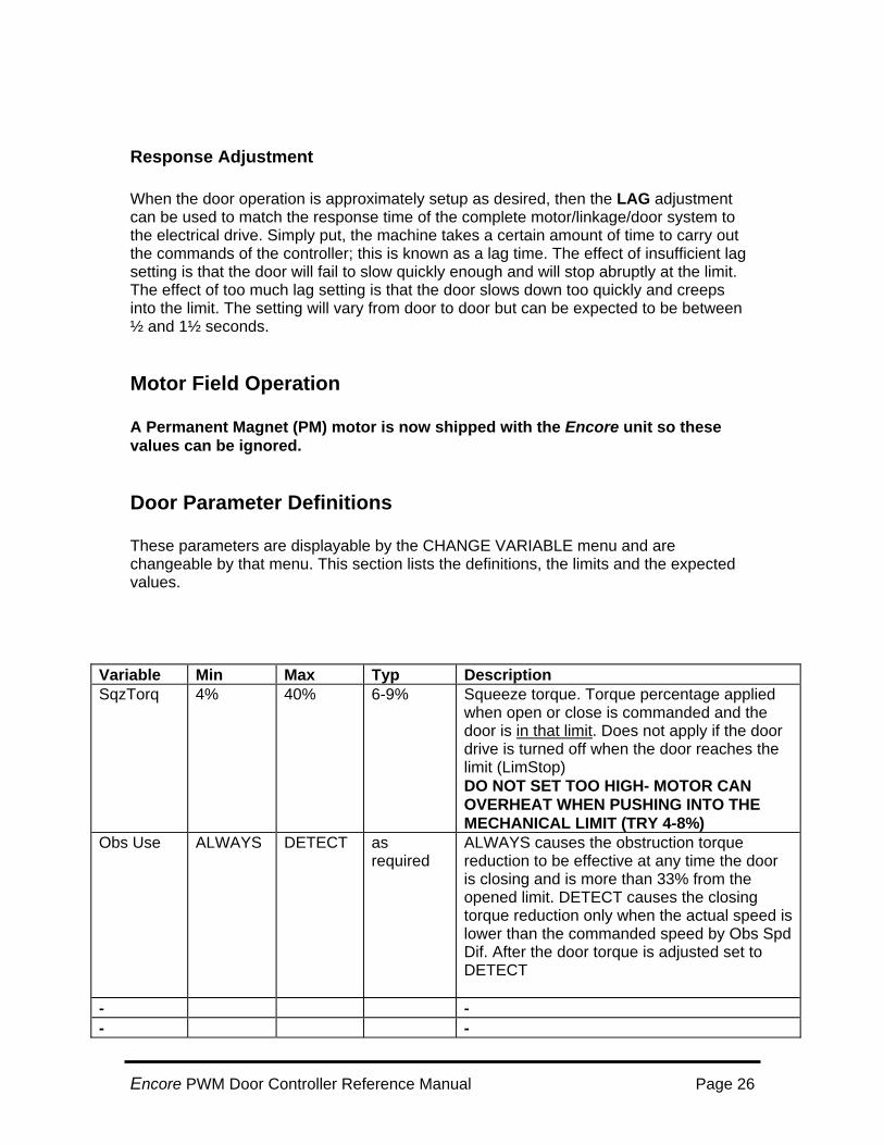
Door Parameter Definitions These parameters are displayable by the CHANGE VARIABLE menu and are changeable by that menu. This section lists the definitions, the limits and the expected values.
Variable Min Max Typ Description SqzTorq 4% 40% 6-9% Squeeze torque. Torque percentage applied
when open or close is commanded and the door is in that limit. Does not apply if the door drive is turned off when the door reaches the limit (LimStop) DO NOT SET TOO HIGH- MOTOR CAN OVERHEAT WHEN PUSHING INTO THE MECHANICAL LIMIT (TRY 4-8%)
Obs Use ALWAYS DETECT as required
ALWAYS causes the obstruction torque reduction to be effective at any time the door is closing and is more than 33% from the opened limit. DETECT causes the closing torque reduction only when the actual speed is lower than the commanded speed by Obs Spd Dif. After the door torque is adjusted set to DETECT
- - - -
Encore PWM Door Controller Reference Manual Page 26
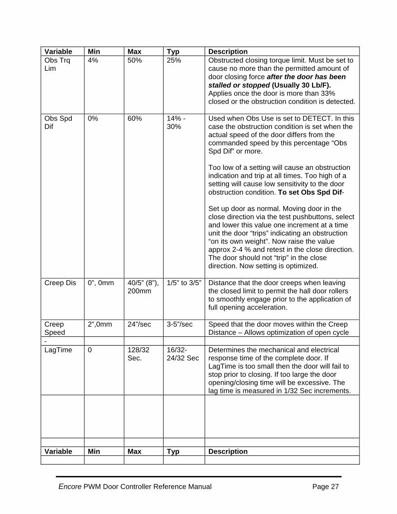
Variable Min Max Typ Description Obs Trq Lim
4% 50% 25% Obstructed closing torque limit. Must be set to cause no more than the permitted amount of door closing force after the door has been stalled or stopped (Usually 30 Lb/F). Applies once the door is more than 33% closed or the obstruction condition is detected.
Obs Spd Dif
0% 60% 14% - 30%
Used when Obs Use is set to DETECT. In this case the obstruction condition is set when the actual speed of the door differs from the commanded speed by this percentage “Obs Spd Dif” or more. Too low of a setting will cause an obstruction indication and trip at all times. Too high of a setting will cause low sensitivity to the door obstruction condition. To set Obs Spd Dif- Set up door as normal. Moving door in the close direction via the test pushbuttons, select and lower this value one increment at a time unit the door “trips” indicating an obstruction “on its own weight”. Now raise the value approx 2-4 % and retest in the close direction. The door should not “trip” in the close direction. Now setting is optimized.
Creep Dis 0”, 0mm 40/5” (8”), 200mm
1/5” to 3/5” Distance that the door creeps when leaving the closed limit to permit the hall door rollers to smoothly engage prior to the application of full opening acceleration.
Creep Speed
2”,0mm 24”/sec 3-5”/sec Speed that the door moves within the Creep Distance – Allows optimization of open cycle
- LagTime 0 128/32
Sec. 16/32-24/32 Sec
Determines the mechanical and electrical response time of the complete door. If LagTime is too small then the door will fail to stop prior to closing. If too large the door opening/closing time will be excessive. The lag time is measured in 1/32 Sec increments.
Variable Min Max Typ Description
Encore PWM Door Controller Reference Manual Page 27
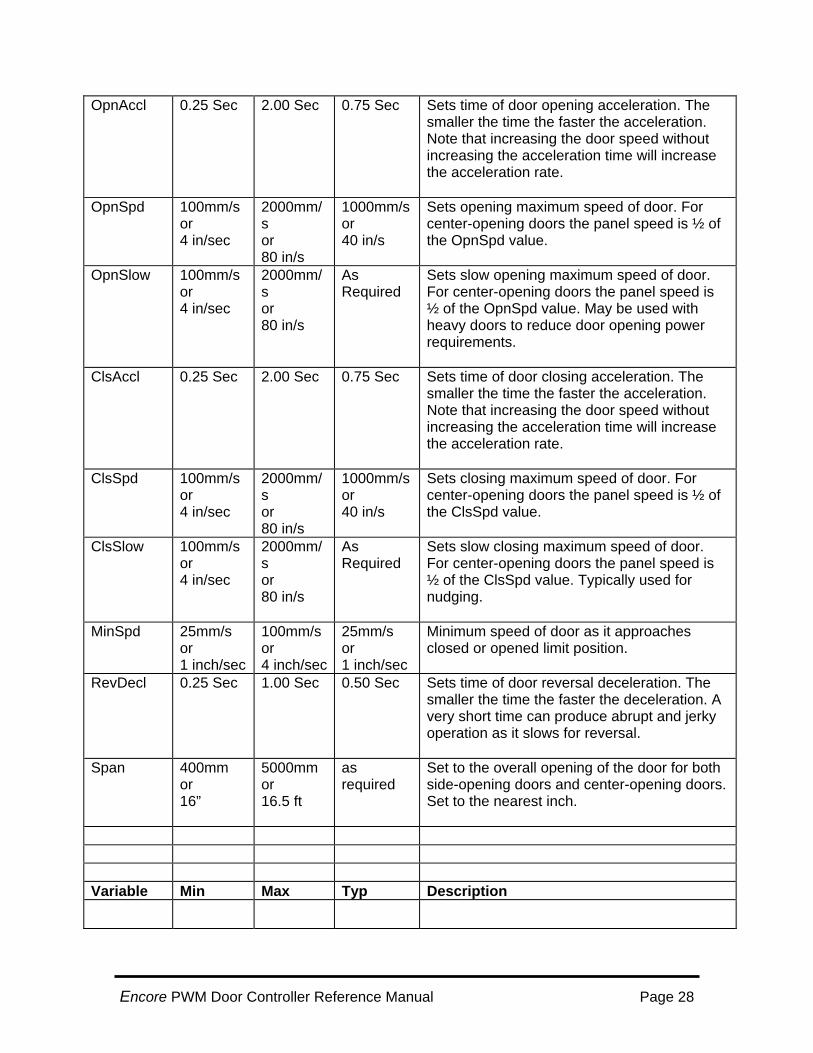
OpnAccl 0.25 Sec 2.00 Sec 0.75 Sec Sets time of door opening acceleration. The smaller the time the faster the acceleration. Note that increasing the door speed without increasing the acceleration time will increase the acceleration rate.
OpnSpd 100mm/s or 4 in/sec
2000mm/s or 80 in/s
1000mm/s or 40 in/s
Sets opening maximum speed of door. For center-opening doors the panel speed is ½ of the OpnSpd value.
OpnSlow 100mm/s or 4 in/sec
2000mm/s or 80 in/s
As Required
Sets slow opening maximum speed of door. For center-opening doors the panel speed is ½ of the OpnSpd value. May be used with heavy doors to reduce door opening power requirements.
ClsAccl 0.25 Sec 2.00 Sec 0.75 Sec Sets time of door closing acceleration. The smaller the time the faster the acceleration. Note that increasing the door speed without increasing the acceleration time will increase the acceleration rate.
ClsSpd 100mm/s or 4 in/sec
2000mm/s or 80 in/s
1000mm/s or 40 in/s
Sets closing maximum speed of door. For center-opening doors the panel speed is ½ of the ClsSpd value.
ClsSlow 100mm/s or 4 in/sec
2000mm/s or 80 in/s
As Required
Sets slow closing maximum speed of door. For center-opening doors the panel speed is ½ of the ClsSpd value. Typically used for nudging.
MinSpd 25mm/s or 1 inch/sec
100mm/s or 4 inch/sec
25mm/s or 1 inch/sec
Minimum speed of door as it approaches closed or opened limit position.
RevDecl 0.25 Sec 1.00 Sec 0.50 Sec Sets time of door reversal deceleration. The smaller the time the faster the deceleration. A very short time can produce abrupt and jerky operation as it slows for reversal.
Span 400mm or 16”
5000mm or 16.5 ft
as required
Set to the overall opening of the door for both side-opening doors and center-opening doors. Set to the nearest inch.
Variable Min Max Typ Description
Encore PWM Door Controller Reference Manual Page 28

DrMass 0 2000 Kg or 2500 Lb.
Per Job values
Used to calculate the closing energy of the doors. Mass should include all panels of both hall and car doors.
- - - - - - LimStop Neither Yes Both
or Closed
Usually Neither
Some doors require that the door torque be removed when the limit is reached otherwise the door may re-open as the operator continues over-center. Most door operators include physical limits that will stop the door. May be set so that torque is removed on both limits (Yes both) in the close direction only (Closed) or that torque remains on the door in the limit (Neither)
MF Run% 5% 95% 50% Sets field percent of operation from 5% of bus voltage (10V) up to 95% (150V).Not applicable for PM motors.
CentOpn No Yes As Required
Set Yes for center-opening doors. Set to No for side-opening doors. Used in determining the closing energy of the door(s).
ExOut See Right See Right As Required
This determines the purpose of the third output signal of the door controller. It may be set to on of the following: Pre DCL - Set as pre DCL signal Running - Set as a running indicator Code Dist – Set to show code distance (2”/SO or 1”/CO) from limit.
ExIn Not Used Safety Edge
As Required
When selected as a Safety Edge signal activation will cause an immediate obstruction condition when the door is closing. Also sets the door torque in Slow/Nudging (see page 15) Obstruction torque limiting applies to the closing direction only.
Pre DCL 0” 6” As Required
When the ExOut programmable output is set to PreDCL, this parameter defines the distance prior to the actual closing limit that the ExOut output (P9 terminals 6 &5) becomes active
Variable Min Max Typ Description
Encore PWM Door Controller Reference Manual Page 29
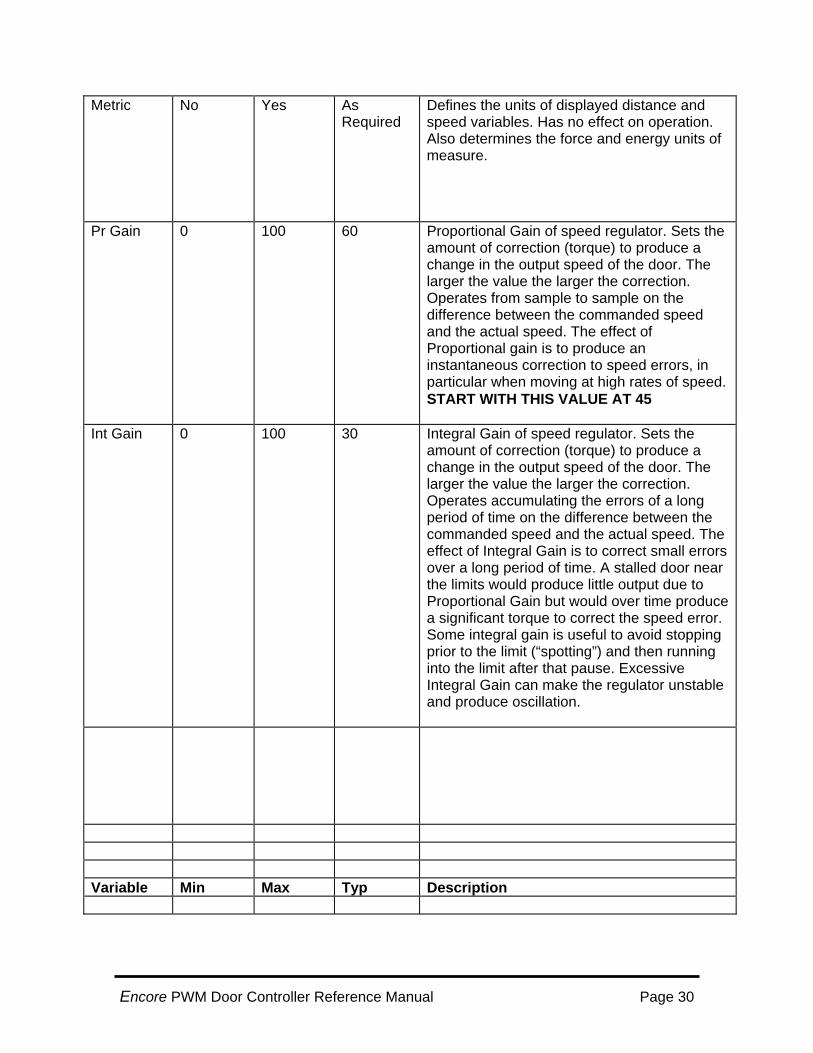
Metric No Yes As Required
Defines the units of displayed distance and speed variables. Has no effect on operation. Also determines the force and energy units of measure.
Pr Gain 0 100 60 Proportional Gain of speed regulator. Sets the amount of correction (torque) to produce a change in the output speed of the door. The larger the value the larger the correction. Operates from sample to sample on the difference between the commanded speed and the actual speed. The effect of Proportional gain is to produce an instantaneous correction to speed errors, in particular when moving at high rates of speed. START WITH THIS VALUE AT 45
Int Gain 0 100 30 Integral Gain of speed regulator. Sets the amount of correction (torque) to produce a change in the output speed of the door. The larger the value the larger the correction. Operates accumulating the errors of a long period of time on the difference between the commanded speed and the actual speed. The effect of Integral Gain is to correct small errors over a long period of time. A stalled door near the limits would produce little output due to Proportional Gain but would over time produce a significant torque to correct the speed error. Some integral gain is useful to avoid stopping prior to the limit (“spotting”) and then running into the limit after that pause. Excessive Integral Gain can make the regulator unstable and produce oscillation.
Variable Min Max Typ Description
Encore PWM Door Controller Reference Manual Page 30

Dif Gain 0 100 32 Differential gain of speed regulator. Sets the amount of correction based only on the change in the proportional torque command. For example if the speed is too low then using differential gain will cause the torque to increase momentarily above that of just proportional gain. In effect it gives an extra torque to force the motor to respond more rapidly. Excessive differential gain can cause motor oscillation.
- - Close Tgt 0/5" 30/5" Job setting Sets a target stopping position prior to
reaching the door limit. Used to insure door has reached final closing speed prior to limit. Also helpful in adjusting final approaching speed.
- OpenTgt 0/5" 30/5" Job setting Sets a target stopping position prior to
reaching the door limit. Used to insure door has reached final closing speed prior to limit. Also helpful in adjusting final approaching speed.
- Tach Filter 1 4 1 Determines the number of tachometer
(encoder) readings to average to obtain the door speed. Excessive settings can cause motor oscillation. Useful when the encoder speed is not high or a low-resolution encoder is used.
Var Gain 30% 100% 100% Variable gain allows lower gain settings when the door is moving slower. This causes a slower response and may reduce jitter or cogging when moving slowly. Unless needed this parameter should remain at 100%
- - -
- - Variable Min Max Typ Description
Encore PWM Door Controller Reference Manual Page 31
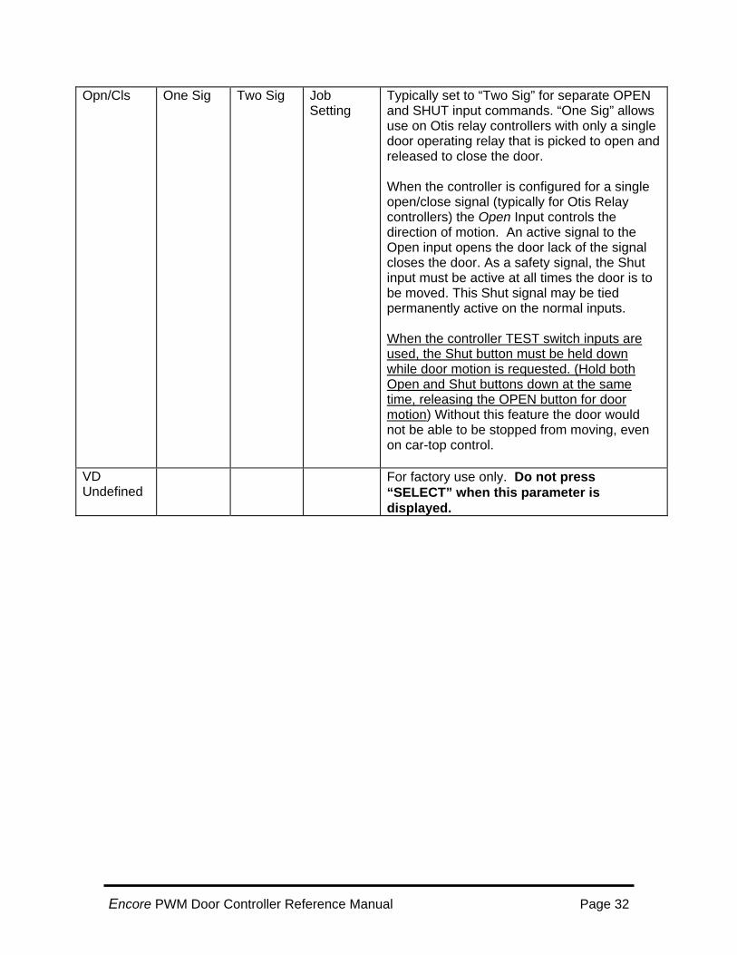
Opn/Cls One Sig Two Sig Job Setting
Typically set to “Two Sig” for separate OPEN and SHUT input commands. “One Sig” allows use on Otis relay controllers with only a single door operating relay that is picked to open and released to close the door. When the controller is configured for a single open/close signal (typically for Otis Relay controllers) the Open Input controls the direction of motion. An active signal to the Open input opens the door lack of the signal closes the door. As a safety signal, the Shut input must be active at all times the door is to be moved. This Shut signal may be tied permanently active on the normal inputs. When the controller TEST switch inputs are used, the Shut button must be held down while door motion is requested. (Hold both Open and Shut buttons down at the same time, releasing the OPEN button for door motion) Without this feature the door would not be able to be stopped from moving, even on car-top control.
VD Undefined
For factory use only. Do not press “SELECT” when this parameter is displayed.
Encore PWM Door Controller Reference Manual Page 32
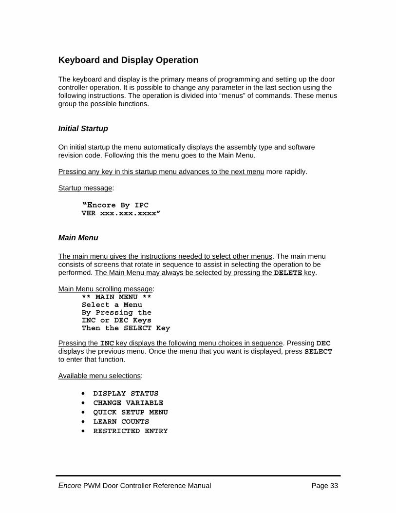
Keyboard and Display Operation The keyboard and display is the primary means of programming and setting up the door controller operation. It is possible to change any parameter in the last section using the following instructions. The operation is divided into “menus” of commands. These menus group the possible functions.
Initial Startup On initial startup the menu automatically displays the assembly type and software revision code. Following this the menu goes to the Main Menu. Pressing any key in this startup menu advances to the next menu more rapidly. Startup message:
“Encore By IPC VER xxx.xxx.xxxx”
Main Menu The main menu gives the instructions needed to select other menus. The main menu consists of screens that rotate in sequence to assist in selecting the operation to be performed. The Main Menu may always be selected by pressing the DELETE key. Main Menu scrolling message:
** MAIN MENU ** Select a Menu By Pressing the INC or DEC Keys Then the SELECT Key
Pressing the INC key displays the following menu choices in sequence. Pressing DEC displays the previous menu. Once the menu that you want is displayed, press SELECT to enter that function. Available menu selections:
• DISPLAY STATUS • CHANGE VARIABLE • QUICK SETUP MENU • LEARN COUNTS • RESTRICTED ENTRY
Encore PWM Door Controller Reference Manual Page 33

Display Status Screen This menu is used to watch/confirm the operation of the door controller when in operation. 1. Press the INC and DEC keys. Note your screen may initially be blank this is OK 2. Exit by ENTER or DELETE. The LCD display provides the following messages:
“DOL, DCL, xx, X, O, C, or S”
DOL = On Door Opened Limit DCL = On Door Closed Limit X = Extra Input is Active O = Receiving an Open Command (From pushbutton or external Open input) C = Receiving Close Command (From pushbutton or external Open input) S = Receiving Slow Command (From pushbutton or external Open input) The display item “xx” can have different settings depending on the use of the EXOUT parameter. For example when used for a pre-closed limit, the display will show: PC = On Pre-close Limit. When the EXOUT is used for a running indicator the display will show: RN = Door Motor Running. The Speed display provides the following: mm/s: xxxx T: xxxx (mm/s or in/s is speed commanded)
in S: xxxx T: xxxx (T is tachometer (actual) speed measured.) The Torque display provides the following: Torque: xxx% ( “xxx” is the percent of full output torque, can be -100% to +100% The Encoder display provides the position of the door in counts as follows: Encoder:xxxxxxxx Where xxxxxxxx is the door position count. (Closed is a count of zero).
Display Status Screen Contd:
Encore PWM Door Controller Reference Manual Page 34
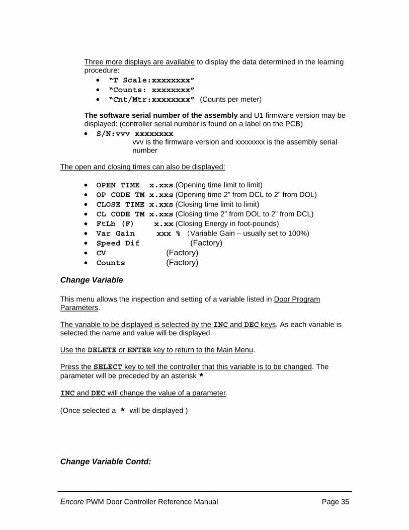
Three more displays are available to display the data determined in the learning procedure:
• “T Scale:xxxxxxxx” • “Counts: xxxxxxxx” • “Cnt/Mtr:xxxxxxxx” (Counts per meter)
The software serial number of the assembly and U1 firmware version may be displayed: (controller serial number is found on a label on the PCB) • S/N:vvv xxxxxxxx
vvv is the firmware version and xxxxxxxx is the assembly serial number The open and closing times can also be displayed:
• OPEN TIME x.xxs (Opening time limit to limit) • OP CODE TM x.xxs (Opening time 2” from DCL to 2” from DOL) • CLOSE TIME x.xxs (Closing time limit to limit) • CL CODE TM x.xxs (Closing time 2” from DOL to 2” from DCL) • FtLb (F) x.xx (Closing Energy in foot-pounds) • Var Gain xxx % (Variable Gain – usually set to 100%) • Speed Dif (Factory) • CV (Factory) • Counts (Factory)
Change Variable This menu allows the inspection and setting of a variable listed in Door Program Parameters. The variable to be displayed is selected by the INC and DEC keys. As each variable is selected the name and value will be displayed. Use the DELETE or ENTER key to return to the Main Menu. Press the SELECT key to tell the controller that this variable is to be changed. The parameter will be preceded by an asterisk * INC and DEC will change the value of a parameter. (Once selected a * will be displayed )
Change Variable Contd:
Encore PWM Door Controller Reference Manual Page 35

To change the value once selected: Press the INC or DEC key. (When the limit of a variable is reached then the key will have no effect.) To save the value entered, Press the ENTER key. (There is a small delay while the new value is written to memory) To quit and not save the changed value, Press DELETE or SELECT.
Refer to the changeable variables on pages 22-28
Encore PWM Door Controller Reference Manual Page 36

Quick Setup Menu Caution: This command will replace the existing parameters with a factory-defined set. A learning procedure will be necessary following the use of Quick Setup. This menu allows the loading of a pre-defined set of parameters that are factory determined to be a starting point for different types of doors. Use the INC or DEC key to display the predefined sets. The setups are stored and accessed by door operator type. Select the type of door controller in use and then select the opening size. If you do not find your particular operator in the list load one of the GAL/Westinghouse setups and change the variables to suit your application. To load the displayed setup, use the ENTER key once to choose and then again to confirm. To quit and keep the original setup, press either DELETE or SELECT Once the setup is complete the display shows; “SETUP Loaded” “NOW LEARN COUNTS”
Learning Menu Learning is the means by which the controller determines the number of counts per distance and the speed calibrations. It need be performed when the SPAN is changed or when the Quick Setup menu is used. It is required only once with the resulting variables stored in permanent memory. The display shows
“LEARN COUNTS” “ENT to Confirm” “Other Key Cancels”
Press ENTER to begin the learning. (Pressing any key before learning completes cancels the learning process and displays and the LCD display will indicate: “Learning Cancelled” Learning displays the following messages: Closing to Limit Reclose to Limit (only if the motor runs in reverse) Opening to Limit Learning Counts Learn xxxxxx tt xx... is encoder count, where tt is motor torque Learn Save Data Learn Completed
Encore PWM Door Controller Reference Manual Page 37
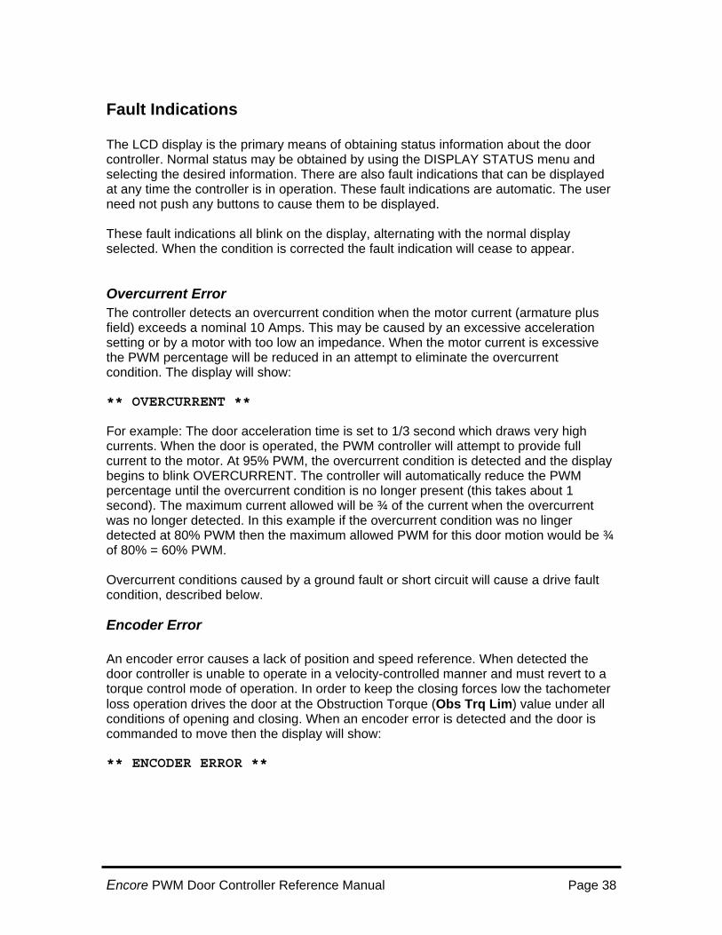
Fault Indications The LCD display is the primary means of obtaining status information about the door controller. Normal status may be obtained by using the DISPLAY STATUS menu and selecting the desired information. There are also fault indications that can be displayed at any time the controller is in operation. These fault indications are automatic. The user need not push any buttons to cause them to be displayed. These fault indications all blink on the display, alternating with the normal display selected. When the condition is corrected the fault indication will cease to appear.
Overcurrent Error The controller detects an overcurrent condition when the motor current (armature plus field) exceeds a nominal 10 Amps. This may be caused by an excessive acceleration setting or by a motor with too low an impedance. When the motor current is excessive the PWM percentage will be reduced in an attempt to eliminate the overcurrent condition. The display will show: ** OVERCURRENT ** For example: The door acceleration time is set to 1/3 second which draws very high currents. When the door is operated, the PWM controller will attempt to provide full current to the motor. At 95% PWM, the overcurrent condition is detected and the display begins to blink OVERCURRENT. The controller will automatically reduce the PWM percentage until the overcurrent condition is no longer present (this takes about 1 second). The maximum current allowed will be ¾ of the current when the overcurrent was no longer detected. In this example if the overcurrent condition was no linger detected at 80% PWM then the maximum allowed PWM for this door motion would be ¾ of 80% = 60% PWM. Overcurrent conditions caused by a ground fault or short circuit will cause a drive fault condition, described below.
Encoder Error An encoder error causes a lack of position and speed reference. When detected the door controller is unable to operate in a velocity-controlled manner and must revert to a torque control mode of operation. In order to keep the closing forces low the tachometer loss operation drives the door at the Obstruction Torque (Obs Trq Lim) value under all conditions of opening and closing. When an encoder error is detected and the door is commanded to move then the display will show: ** ENCODER ERROR **
Encore PWM Door Controller Reference Manual Page 38
Fault Indications Contd: The encoder error condition is detected by a period of 1/8 of a second with a commanded speed greater than zero and with no changes in the encoder value. The encoder speed checking is performed at all times the door is in motion and is between the door limits. The error can be caused by an unconnected or broken wire to the encoder, by a defective encoder or defective door controller PCBA. The encoder error can also be caused by no door motion at all when closing and obstructed. This is possible but often will not happen since even small door movements will give different encoder counts.
Drive Fault Error The drive fault condition is detected by the hardware of the door controller. It is monitored at all times, even when the drive is not operating. The drive fault condition detects the following conditions:
Low Input Voltage Short Circuit Current (Current over 30 Amps) Over-temperature
Drive fault conditions are serious and require an investigation as to the cause. Failure to determine the cause of a drive fault may result in erratic operation or damage to electrical equipment. When any of these conditions are detected the hardware removes all PWM drive from the motor and notifies the microprocessor. When a drive fault is detected then the display will blink the following for a period of three seconds. ** DRIVE FAULT ** Drive faults may be caused by a grounded motor, shorted motor armature excessively high settings leading to high temperatures or lastly, low input voltage.
Encore PWM Door Controller Reference Manual Page 39
Obstruction Error The obstruction error is displayed when the “Obs Use” “DETECT” is set and the speed is reduced by at least Obs Spd Dif percentage while the door is closing (Essentially the actual speed is less by some percentage than the commanded speed). For example if the commanded speed is set at 36 inches / sec and Obs Spd Dif is 20%, then an actual speed of 28.8 inches per second or less (36 inches/sec – 20%) will cause an obstruction condition Once “tripped” on “Obstruction error”, the closing torque is limited to the value of Obs Trq Lim. The obstruction condition will automatically reset when the door completes it closed movement. Obstruction may also be caused by an input to the Extra Input signal from a safety edge or a light curtain or while ObsSe is being used for nudging (SLOW) . This allows the door detector to signal the door controller of an impending collision and reduce the torque to the value set for obstruction. This will typically slow the door and reduce the force of impact. When this signal is activated there is no delay waiting for the controller to begin slowing the door. The display shows the following while in obstruction: ** OBSTRUCTION ** Note that Obstruction Error will also indicate in the LCD during the last 1/3 of normal close travel. This is normal.
Motor Limit Error The motor limit error will occur when the controller is commanded to open or close and the door is unable to reach the desired limit position within 120 seconds. The action of the controller is to reduce to the obstruction torque output value and to reduce the motor field from the value set for running (typically 70%) down to a 30% setting. The display shows the following while in Motor Limiting
** Motor Limit **
Encore PWM Door Controller Reference Manual Page 40
Installing New Software The software of the Door controller is contained in a non-removable IC on the PCBA assembly. If new software is provided it must be loaded on to the IC using a separate loader PCBA, which plugs into the door controller on P5. Once the program has been loaded it replaces the original program. It does not replace the current adjustment settings or learned parameters. The loader assembly contains a special program in socket EP0, which controls the loading process. This IC need not be removed unless a newer one is provided with the software update.
Step by Step Loading Procedure 1. Install the new program EPROM (27C4096 type) into EP1 of the loader assembly.
(3010-10-0). 2. Verify notch on EPROM is opposite the EP1 printed on the PCBA 3. Verify no pins of the EPROM are bent under when inserted. 4. Remove power from the door controller 5. Install the loader PCBA to the 48-pin P5 connector on the door controller PCBA. This
connector fits only in one orientation. Do not force the connector onto the PCBA. 6. Apply power to the Door Controller. Normal door operation is disabled at this time. 7. All of the following steps are automatic until the loading procedure completes. 8. The memory is erased with LED's RUN, EP1 and EP2 on and blinking. 9. When erased the RUN and OK LED's illuminate. 10. When loading the contents of EP1 the RUN, and EP1 LED's illuminate and blink. 11. Next the contents are verified with RUN, EP1 and VER illuminated. 12. Successful completion is indicated by the OK and VER LED’s blinking. 13. If successful, remove power and remove the loader assembly. If the ERR LED
illuminates skip to step 15. 14. Restore power to begin normal operation. The software version number will be
shown on the display and may be compared to the label on the EPROM of the loader assembly.
15. If the ERR LED illuminates on the loader PCBA then press and release the RESET push button on the loader PCBA to repeat the loading process. First check that the loader is firmly installed, and the EPROM is correctly installed. Failure to load may indicate one of the following
• Program EP1 EPROM incorrectly installed • EPROM EP1 is not for this assembly • Loader assembly not seated correctly • Loader assembly removed prior to completion. • EEPROM on PCBA failed to erase • EEPROM on PCBA failed to load new program
Encore PWM Door Controller Reference Manual Page 41
How Closed Loop Pulse Width Modulation Works Pulse Width Modulation (PWM) is a high-speed means of driving a motor (or other electronic load) to cause a controlled and adjustable speed regulation. As used in this product PWM calculates the difference between the desired speed, set by the door parameters) and the actual speed of the door, as measured by the encoder. This difference is then used to command the door by applying power producing torque to rotate the motor. The adjustment of the applied power to compensate for the difference between the desired speed and the actual speed happens 500 times per second. This portion of the control is known as feedback control or closed-loop control. As an example of closed loop control: If the door is prevented from opening as it normally would, then the applied current is increased by changing the PWM percentage to give the motor a higher opening torque. If the door is then allowed to open normally, the torque is reduced almost instantly when the door reaches its desired speed. Likewise, pulling the door open will result in the motor providing reverse torque to prevent the door from opening too fast (such as when the door is slowing to a stop). Providing power to the motor for movement is accomplished by outputting a signal that alternates rotation clockwise and then anti-clockwise. This signal is applied at all times the door is in motion. To make the door stop the signal applies 50% clockwise rotation torque and 50% counterclockwise rotation torque. As a result the door does not move. So why doesn’t the door rotate back and forth? Simple, the clockwise-counterclockwise command is changed 20,000 times per second. So the door sees only the average command which at 50%-50% is zero speed. In order to move clockwise the percentages are changed from 50%-50% to 60% clockwise and 40% counterclockwise. The result is that the motor is able to respond to the difference of the percentages. To run counterclockwise the percentages are simply reversed (40% CW - 60% CCW). The amount of force (torque) output varies depending on the percentages. Full torque clockwise is typically 96% CW to 4% CCW while low torque clockwise would be 53% CW to 47% CCW. Why doesn’t the motor get really hot since we are applying power in one direction or another any time the motor is turned on? The answer is the inductance of the motor. Inductance wants to prevent the change in current in the inductors. The inductors are the motor armature and motor field. So while the controller changes it’s polarity 20,000 times per second the motor’s inductance prevents the current from responding quickly. The motor does see a high voltage at all times, but only the average current set by the PWM percentages is sensed by the motor. If the motor had very little inductance then it would dissipate full power at all times and become very hot regardless of the PWM percentages.
Encore PWM Door Controller Reference Manual Page 42

Electrical Specifications Input Power
115VAC +/- 10% at 15A capability 130VDC +/- 10% at 15A capability May operate from 90VAC or 130VDC at reduced output torque
Motor Output (Armature) 160VDC maximum at 6A, (up to 9A for 60 seconds) measured at 115VAC input power.
Operating Temperature 0-50 Centigrade
Heat Sink Temperature Less than 85 Centigrade
DOL/DCL Inputs Contact Closures, 10 mA current
Encoder 5VDC power at 100mA maximum, Quadrature outputs (totem-pole or open-collector). Minimum 300 counts per inch of door travel
Limit Outputs Rated at 24 to 300 V (AC or DC) Maximum current each output is 100 mA. Do not overload or device will be damaged.
Controller Signal Inputs 120V (AC or DC) with 20K load resistors Switch at 35% (8V / 45V) 24V is available as special order(AC or DC) with 3.3K load resistors (Please contact the Factory)
Encore PWM Door Controller Reference Manual Page 43