end-suction fire pumpset diesel engine driven - lubi pumps · lbsd end-suction fire pumpset diesel...
TRANSCRIPT
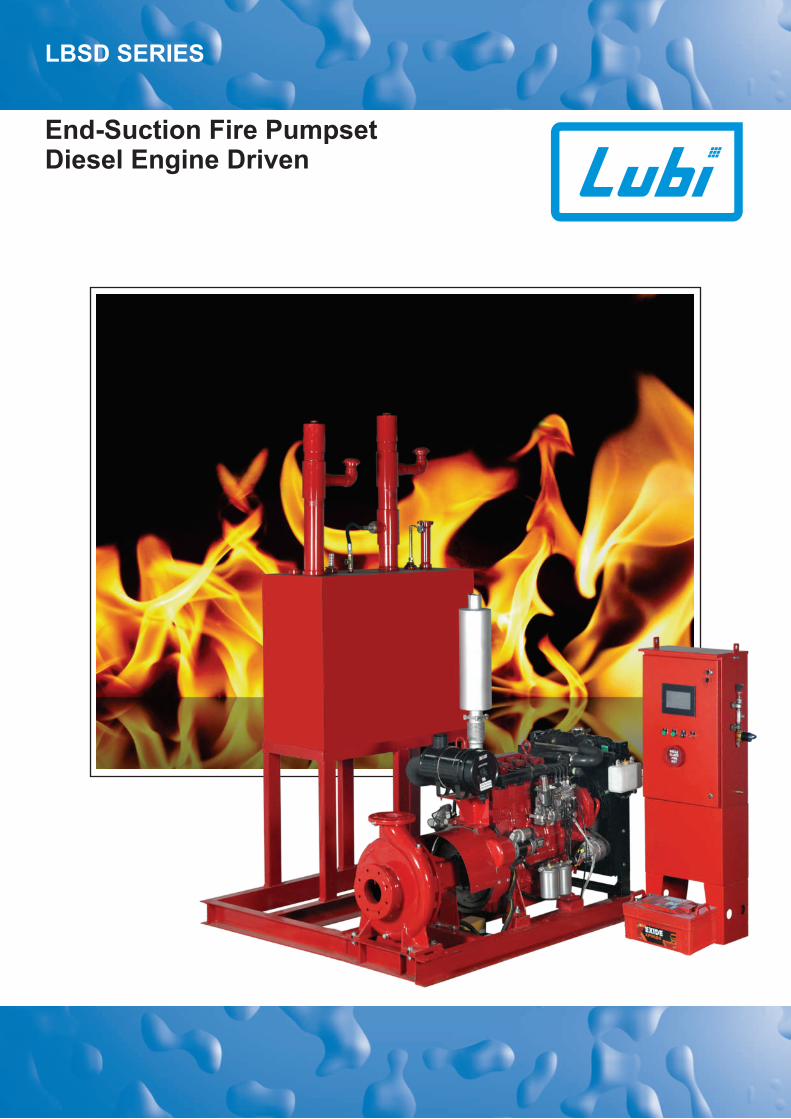
End-Suction Fire Pumpset Diesel Engine Driven
LBSD SERIES
LBSD END-SUCTION FIRE PUMPSETDIESEL ENGINE DRIVEN
INTRODUCTION
Lubi offers LBSD series state-of-the-art fire pumpset with
diesel engine driven, single-stage end-suction pump.
These pumpsets are typically used in fire-fighting
applications for supplying water to fire hose reels, fire
hydrants or sprinkler systems.
Pumps have a discharge range from 400 to1500 USgpm and
the head range from 47 to 165 psi.
These fire pumpsets meet or exceed the requirements of
NFPA 20.
Installations of these pumpsets would ensure the safety of
human life, buildings, expensive plants and equipments.
LBSD fire pumpset shall be used only where a positive
suction is provided as specified in NFPA 20.
The fire pumpset typically consists of the following
equipments:
Pump
Diesel engine assembled with
- cooling system
- fuel system
- battery system
- exhaust system
Fire pump controller
Suction and discharge gauges
Air relief valve
Common base plate
Note: For your jockey pump requirements kindly refer our
literature for LCR and/or LES pumps.
All above equipments except fuel supply tank and fire pump
controller are mounted on a common base frame.
Lubi can also supply Packaged fire pumping system with all
required accessories ready for site installation.
The LBSD fire pumpsets are used in small capacity, diesel
engine driven fire-fighting applications for supplying water to
fire hose reels, fire hydrants or sprinkler systems in areas
which are prone to the hazards of fire. The typical
applications are as follow:
Commercial complexes and high rise buildings
Petrochemical industries and Gas plants
Airports and ports
Jetties
Marine applications
Power stations and transformer stations
Chemical industries
Manufacturing plants
Fire-work industries
Warehouses/godowns.
APPLICATIONS
TYPE KEY
LBS D 040100400 B
Type range
LBS = Single-stage end- suction pump
Fire pumpset
D = Diesel engine driven pump
040 = 40 hp600 = 600 hp
Diesel engine rating [hp]Model Diesel engine speed [rpm]
B = 1500 rpmC = 1800 rpmD = 2000 rpm
FEATURES AND BENEFITS
LBSD fire pumpset offers all features & benefits as
mentioned in our LBS pump standard series data booklet.
Following are the additional features & benefits offered by
these pumpsets:
State-of-the-art design fire pumping system.
NFPA-20 design
Compact diesel engine driven pump package
Rugged construction
More economical than Horizontal Split Case diesel fire
pump packages
Back pull-out design which simplifies inspection and
maintenance without disturbing pipe work
The pump impellers are dynamically balanced to grade
6.3 of ISO 1940
Low NPSH requirements
Automatic air relief valve
Efficient operation
Lower initial cost
Reduced installation time and cost
Simplified piping design
Suitable for space saving installation systems and
retrofit applications
Easy access to all working parts
Ease of maintenance
Single source unit responsibility.

PERFORMANCE RANGE - DIESEL ENGINE DRIVEN
LBSD
NOMINAL FLOW[USgpm] 1500 1800 2000
DIESEL ENGINE SPEED [rpm]
400
450
500
600
750
1000
1500
18931514 1703 5678378528392271
Q (USgpm)400 15001000750600500450
30
50
70
90
110
130
150
170
190
p(p
si)
100
150
200
250
300
350
400
Hft
.
400 - 1500 USgpm
LBSDDIESEL
Q (l/min)400 U
Sg
pm
79 -
123 p
si
1500 U
Sg
pm
50 -
78 p
si
1000 U
Sg
pm
56 -
96 p
si
750 U
Sg
pm
49 -
160 p
si
600 U
Sg
pm
55 -
165 p
si
500 U
Sg
pm
47 -
148 p
si
450 U
Sg
pm
76 -
120 p
si
AVAILABLE
END-SUCTION FIRE PUMPSETDIESEL ENGINE DRIVEN
DESIGN FEATURES - DIESEL ENGINE DRIVEN
LBSD END-SUCTION FIRE PUMPSETDIESEL ENGINE DRIVEN
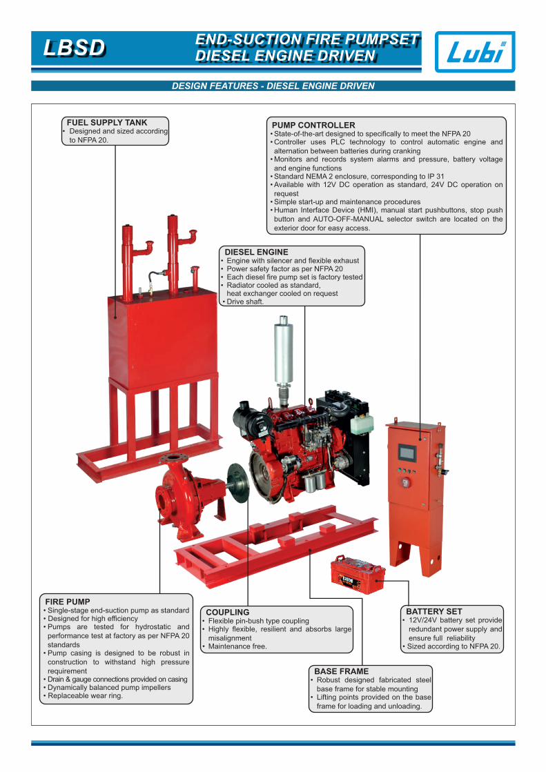
FIRE PUMP• Single-stage end-suction pump as standard • Designed for high efficiency • Pumps are tested for hydrostatic and performance test at factory as per NFPA 20 standards• Pump casing is designed to be robust in
construction to withstand high pressure requirement
• Drain & gauge connections provided on casing• Dynamically balanced pump impellers• Replaceable wear ring.
FUEL SUPPLY TANK• Designed and sized according to NFPA 20.
DIESEL ENGINE• Engine with silencer and flexible exhaust• Power safety factor as per NFPA 20• Each diesel fire pump set is factory tested• Radiator cooled as standard, heat exchanger cooled on request• Drive shaft.
PUMP CONTROLLER• State-of-the-art designed to specifically to meet the NFPA 20• Controller uses PLC technology to control automatic engine and alternation between batteries during cranking• Monitors and records system alarms and pressure, battery voltage and engine functions• Standard NEMA 2 enclosure, corresponding to IP 31• Available with 12V DC operation as standard, 24V DC operation on request• Simple start-up and maintenance procedures• Human Interface Device (HMI), manual start pushbuttons, stop push button and AUTO-OFF-MANUAL selector switch are located on the exterior door for easy access.
COUPLING• Flexible pin-bush type coupling • Highly flexible, resilient and absorbs large misalignment • Maintenance free.
BATTERY SET• 12V/24V battery set provide redundant power supply and ensure full reliability• Sized according to NFPA 20.
BASE FRAME• Robust designed fabricated steel base frame for stable mounting • Lifting points provided on the base frame for loading and unloading.

TECHNICAL SPECIFICATIONS - DIESEL ENGINE DRIVEN
The fire pumpset supplied by Lubi shall include the pump, diesel engine, controller and fittings as detailed in the following technical specifications. All the materials supplied shall be installed as recommended in NFPA 20.
The fire pump shall be horizontal, centrifugal single-stage end-suction, construction specifically labeled for fire service and shall be a
Lubi pump type ________________________ . The fire pump shall be designed to deliver ___________ USgpm of clear water at a
total differential pressure of ___________ psig. The pump shall be connected to the (fire standpipe) (fire sprinkler) (underground fire
main) system. The suction supply for the fire pump shall be from a (public service water main) (elevated storage tank) (ground
storage tank) (underground reservoir) at a maximum pressure of ___________ psig and a minimum pressure of ___________ psig.
The pump casing shall comprise an axial suction port and radial discharge (top centerline) port. Rotating parts shall be removable
and can be dismantled without disturbing the pipe work. Pump casing shall be of cast iron. Impeller shall be bronze, enclosed type
dynamically balanced and keyed to an alloy steel shaft. Shaft shall to be fitted with replaceable S.S AISI 410 sleeves. Shaft shall be
mounted in two deep grooves and regreasable ball bearings. Each stuffing box shall be fitted with lantern rings and graphite gland
packing rings. Packing rings shall be removable without disturbing wetted parts or the pump bearings.
1. PUMP TECHNICAL DETAILS
The fire pump controller shall be factory assembled, wired and tested as a unit prior to shipment. The controller shall be available for
either 12VDC or 24VDC systems. The controller shall include the following standard features:
• NEMA type 2 (IP 31) drip proof metal wall mount or freestanding enclosure
• Dual solid state battery chargers
• Two outer door mounted crank push buttons and two inner panel mounted battery on/off switches
• Outer door mounted key operated AUTO, OFF, MANUAL, mode selector switch
• The controller shall be supplied with a solid state pressure transducer with a range of _______ psi for monitoring system pressure
and providing the feedback to the controller
• Touch screen color Human Interface Device (HMI) display shall be provided of minimum 5 inch size capable of being read in both
direct sunlight or dark lighting conditions
• Touch screen pushbuttons shall be provided on HMI for easy screen navigation, alarm reset, and alarm silencing
• Controller settings shall be programmable through the HMI and shall be protected by passwords
• All features shall be enabled or disabled through the HMI, no jumpers or external wires shall be needed or allowed to activate or
deactivate a feature
• The system status data shall be displayed on the HMI
• Audible alarm shall be provided with alarm silence feature for silenceable alarms
• Data logging shall be possible with real time/date clock to store the continuous pressure log, event log, alarm log and all user
changeable set points and system data. Battery backup of any kind shall not be allowed
• The controller shall be provided with a USB port capable of accepting USB flash memory disk to download historical data of events ,
alarms and pressure logs
• The controller shall feature a RS 485 serial communication port for use with 2 or 4 wire ModBus RTU communication
• Anti condensation space heaters can be provided when controller is installed in a basement having high humidity (optional).
4. FIRE PUMP CONTROLLER DETAILS
3. STANDARD ACCESSORIES DETAILS
The pump shall be supplied with the following accessories:
• Combination suction gauge, 3½” dial type with ¼” cock and lever handle - 1 no.
• Air release valve - 1 no.
• Discharge gauge, 3½” dial type with ¼” cock and lever handle - 1 no.
2. DIESEL ENGINE DETAILS
The fire pump driver shall be a horizontal shaft type internal combustion diesel engine manufactured by: ______________________
Model no. ___________________ with maximum power rated kW __________at _________ rpm. The fire pump shall be directly
coupled through flexible coupling to a diesel engine.
• Each engine shall be provided with two storage battery units.
• Electrolyte shall be added a minimum of 24 hours prior to the time the engine has to be started
• Batteries shall be kept charged at all times and tested frequently (weekly test) to determine condition
• Only distilled water shall be used
• Battery plates shall be kept submerged at all times.
5. BATTERY SET DETAILS
LBSD END-SUCTION FIRE PUMPSETDIESEL ENGINE DRIVEN
TECHNICAL SPECIFICATIONS - DIESEL ENGINE DRIVEN
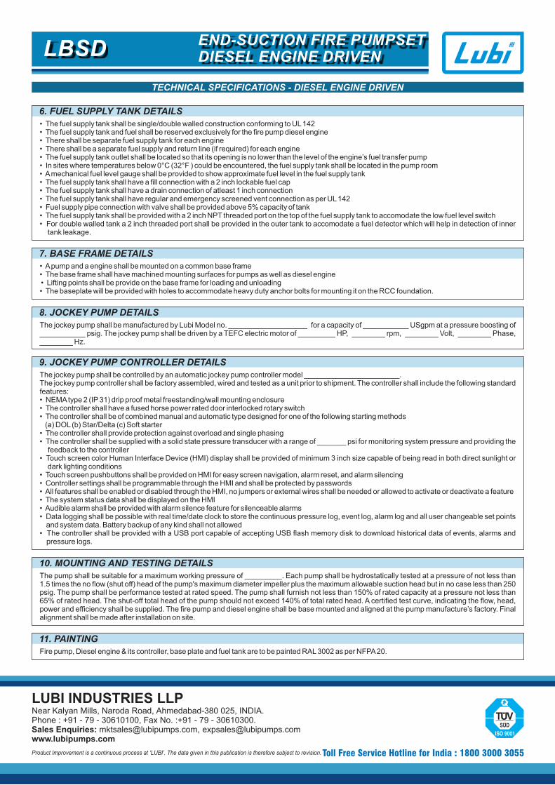
• The fuel supply tank shall be single/double walled construction conforming to UL 142• The fuel supply tank and fuel shall be reserved exclusively for the fire pump diesel engine• There shall be separate fuel supply tank for each engine• There shall be a separate fuel supply and return line (if required) for each engine• The fuel supply tank outlet shall be located so that its opening is no lower than the level of the engine’s fuel transfer pump• In sites where temperatures below 0°C (32°F ) could be encountered, the fuel supply tank shall be located in the pump room • A mechanical fuel level gauge shall be provided to show approximate fuel level in the fuel supply tank• The fuel supply tank shall have a fill connection with a 2 inch lockable fuel cap• The fuel supply tank shall have a drain connection of atleast 1 inch connection• The fuel supply tank shall have regular and emergency screened vent connection as per UL 142• Fuel supply pipe connection with valve shall be provided above 5% capacity of tank• The fuel supply tank shall be provided with a 2 inch NPT threaded port on the top of the fuel supply tank to accomodate the low fuel level switch • For double walled tank a 2 inch threaded port shall be provided in the outer tank to accomodate a fuel detector which will help in detection of inner
tank leakage.
6. FUEL SUPPLY TANK DETAILS
LUBI INDUSTRIES LLPNear Kalyan Mills, Naroda Road, Ahmedabad-380 025, INDIA.Phone : +91 - 79 - 30610100, Fax No. :+91 - 79 - 30610300.Sales Enquiries: [email protected], [email protected]
Product Improvement is a continuous process at ‘LUBI’. The data given in this publication is therefore subject to revision. Toll Free Service Hotline for India : 1800 3000 3055
• A pump and a engine shall be mounted on a common base frame• The base frame shall have machined mounting surfaces for pumps as well as diesel engine • Lifting points shall be provide on the base frame for loading and unloading• The baseplate will be provided with holes to accommodate heavy duty anchor bolts for mounting it on the RCC foundation.
7. BASE FRAME DETAILS
The jockey pump shall be manufactured by Lubi Model no. ___________________ for a capacity of ___________ USgpm at a pressure boosting of ___________ psig. The jockey pump shall be driven by a TEFC electric motor of _________ HP, ________ rpm, ________ Volt, ________ Phase, ________ Hz.
8. JOCKEY PUMP DETAILS
10. MOUNTING AND TESTING DETAILS
The pump shall be suitable for a maximum working pressure of _________. Each pump shall be hydrostatically tested at a pressure of not less than 1.5 times the no flow (shut off) head of the pump's maximum diameter impeller plus the maximum allowable suction head but in no case less than 250 psig. The pump shall be performance tested at rated speed. The pump shall furnish not less than 150% of rated capacity at a pressure not less than 65% of rated head. The shut-off total head of the pump should not exceed 140% of total rated head. A certified test curve, indicating the flow, head, power and efficiency shall be supplied. The fire pump and diesel engine shall be base mounted and aligned at the pump manufacture’s factory. Final alignment shall be made after installation on site.
Fire pump, Diesel engine & its controller, base plate and fuel tank are to be painted RAL 3002 as per NFPA 20.
11. PAINTING
The jockey pump shall be controlled by an automatic jockey pump controller model _______________________.The jockey pump controller shall be factory assembled, wired and tested as a unit prior to shipment. The controller shall include the following standard features:• NEMA type 2 (IP 31) drip proof metal freestanding/wall mounting enclosure• The controller shall have a fused horse power rated door interlocked rotary switch• The controller shall be of combined manual and automatic type designed for one of the following starting methods (a) DOL (b) Star/Delta (c) Soft starter• The controller shall provide protection against overload and single phasing• The controller shall be supplied with a solid state pressure transducer with a range of _______ psi for monitoring system pressure and providing the
feedback to the controller• Touch screen color Human Interface Device (HMI) display shall be provided of minimum 3 inch size capable of being read in both direct sunlight or
dark lighting conditions• Touch screen pushbuttons shall be provided on HMI for easy screen navigation, alarm reset, and alarm silencing• Controller settings shall be programmable through the HMI and shall be protected by passwords • All features shall be enabled or disabled through the HMI, no jumpers or external wires shall be needed or allowed to activate or deactivate a feature• The system status data shall be displayed on the HMI • Audible alarm shall be provided with alarm silence feature for silenceable alarms • Data logging shall be possible with real time/date clock to store the continuous pressure log, event log, alarm log and all user changeable set points
and system data. Battery backup of any kind shall not allowed• The controller shall be provided with a USB port capable of accepting USB flash memory disk to download historical data of events, alarms and
pressure logs.
9. JOCKEY PUMP CONTROLLER DETAILS
LBSD END-SUCTION FIRE PUMPSETDIESEL ENGINE DRIVEN