end-user evaluation of sharp for analysis of sodium-cooled
TRANSCRIPT

ANL-ARC-290
End-User Evaluation of SHARP for Analysis ofSodium-Cooled Fast Reactors
Nuclear Engineering Division

About Argonne National Laboratory Argonne is a U.S. Department of Energy laboratory managed by UChicago Argonne, LLC under contract DE-AC02-06CH11357. The Laboratory’s main facility is outside Chicago, at 9700 South Cass Avenue, Argonne, Illinois 60439. For information about Argonne and its pioneering science and technology programs, see www.anl.gov.
DOCUMENT AVAILABILITY
Online Access: U.S. Department of Energy (DOE) reports produced after 1991 and a growing number of pre-1991 documents are available free via DOE's SciTech Connect (http://www.osti.gov/scitech/) Reports not in digital format may be purchased by the public from the National Technical Information Service (NTIS):
U.S. Department of Commerce National Technical Information Service 5301 Shawnee Rd Alexandra, VA 22312 www.ntis.gov Phone: (800) 553-NTIS (6847) or (703) 605-6000 Fax: (703) 605-6900 Email: [email protected]
Reports not in digital format are available to DOE and DOE contractors from the Office of Scientific and Technical Information (OSTI):
U.S. Department of Energy Office of Scientific and Technical Information P.O. Box 62 Oak Ridge, TN 37831-0062 www.osti.gov Phone: (865) 576-8401 Fax: (865) 576-5728 Email: [email protected]
Disclaimer This report was prepared as an account of work sponsored by an agency of the United States Government. Neither the United States Government nor any agency thereof, nor UChicago Argonne, LLC, nor any of their employees or officers, makes any warranty, express or implied, or assumes any legal liability or responsibility for the accuracy, completeness, or usefulness of any information, apparatus, product, or process disclosed, or represents that its use would not infringe privately owned rights. Reference herein to any specific commercial product, process, or service by trade name, trademark, manufacturer, or otherwise, does not necessarily constitute or imply its endorsement, recommendation, or favoring by the United States Government or any agency thereof. The views and opinions of document authors expressed herein do not necessarily state or reflect those of the United States Government or any agency thereof, Argonne National Laboratory, or UChicago Argonne, LLC.

End-User Evaluation of SHARP for Analysis of Sodium-CooledFast Reactors
prepared byJ.W. Thomas, H. Connaway, J. Grudzinski, Y. Tang, S.N.P. VegendlaNuclear Engineering Division, Argonne National Laboratory
September 30, 2014


End-User Evaluation of SHARP for Analysis of Sodium-Cooled Fast ReactorsSeptember 30, 2014
i
SUMMARY
The DOE Nuclear Energy Advanced Modeling and Simulation (NEAMS) program isdeveloping the SHARP toolkit to support growing reactor analysis needs in other programs.Although SHARP includes physics modules—especially the computational fluid dynamicscode Nek5000 and the structural mechanics tools in Diablo—that have an existing user-basein other fields, most of the analysis and validation efforts for nuclear reactor applications havebeen performed by members of SHARP’s own development team. The SHARP developmentteam includes engineers and computational scientists from a diverse set of backgrounds,including nuclear engineering. However, before the SHARP tools can be adopted by theAdvanced Reactor Technology (ART) program to support the analysis of sodium-cooled fastreactors (SFRs), it would be beneficial for an outside set of analysts and engineers to beginusing SHARP and providing feedback to both programs. The authors of this report werecharged with learning to use SHARP, applying SHARP to SFR analyses of interest to ART,evaluating the tools, and providing a set of recommendations and requirements to guide futuredevelopment efforts by the NEAMS program. The authors are engineers (nuclear, mechanical,and civil) by training; all have experience in modeling and simulation for nuclear energyapplications; all have either supported ART directly or report to a supervisor who does. Thisreport is a formal summary of the findings of this team of engineers—the potential end-usersof SHARP for ART activities. In an informal way, this effort also opened up communicationlines between the SHARP developers and ART engineers, which will continue beyond thescope of this effort.
The selected application for SHARP is that of core structural deformation (i.e. radialexpansion) caused by thermal gradients in the core during normal operating conditions, andthe associated influence on core reactivity and the neutron flux distribution. SHARP’scapabilities may be useful to support both quasi-static analysis needs for core restraint systemdesign, and future needs for transient analysis of reactor safety performance. Because ofcareful design of the core restraint system, radial core expansion is often the dominantnegative reactivity feedback mechanism in postulated fast transient events for SFRs underconsideration by our program. Unfortunately, it is arguably the most difficult to predictaccurately with conventional tools, and the available experimental dataset for validation isscarce. The modeling capabilities being developed under the NEAMS program may supportART’s efforts to reduce capital costs in SFRs while maintaining safety performance, and topromote these design concepts with our international partners. To this end, the SHARPdevelopment team successfully performed a demonstration simulation featuring integratedneutronics, thermal-hydraulics, and structural mechanics simulation with sufficient geometricdetail to represent the key phenomena. The ART end-users have been learning to apply theSHARP models themselves, and evaluate the SHARP team’s efforts in this report.Furthermore, the ART end-users were able to use the SHARP physics modules to develop andanalyze models of other SFR applications and include this experience in their evaluation. Theparticular results of these simulations should be viewed as preliminary, and the authorsunderstand that further work is required to improve the accuracy of the models. The results ofSHARP predictions by the ART end-users reported here should in no way be used to evaluatethe accuracy of the SHARP tools themselves. Rather, the preliminary results of these

End-User Evaluation of SHARP for Analysis of Sodium-Cooled Fast ReactorsSeptember 30, 2014
ii
exercises are included here to provide examples of ART end-users efforts to understand theSHARP tools.
The NEAMS developers have also been working on supporting elements intended to facilitatethe process of developing new SHARP models and analyzing the predicted results. Thisincludes the ORNL computing environment NiCE and the ANL mesh generation tool RGG,among others. These tools are also evaluated by the ART end-users in this report.
The report includes the ART end-users evaluation of the SHARP tools, including the SHARPteam efforts on the core structural deformation demonstration problem, the SHARPneutronics module PROTEUS, the SHARP thermal-hydraulics module Nek5000, the SHARPstructural mechanics module Diablo, as well as the supporting elements NiCE and RGG.Specific recommendations are provided for each code module in dedicated sections in thisreport. The report concludes with a summary of recommendations for the SHARP package.

End-User Evaluation of SHARP for Analysis of Sodium-Cooled Fast ReactorsSeptember 30, 2014
iii
Table of Contents
Summary ................................................................................................................................. iTable of Contents .................................................................................................................. iiiList of Figures ........................................................................................................................ vList of Tables......................................................................................................................... vi1 Objectives and Scope ....................................................................................................... 1
1.1 Technology Transfer .................................................................................................. 11.2 Collaborative Working Relationship ......................................................................... 11.3 SHARP Workflow Improvements ............................................................................. 3
2 Modeling Structural Core Deformation ........................................................................... 42.1 Conventional Approach ............................................................................................. 4
2.1.1 Simulations for Core Restraint Design ....................................................... 42.1.2 Modeling Safety Performance..................................................................... 6
2.2 The SHARP Multi-Physics Approach ....................................................................... 72.2.1 Background on SHARP .............................................................................. 72.2.2 The SHARP Model of Core Deformation................................................... 9
2.3 Evaluation of the SHARP Team’s Multi-Physics Demonstration ........................... 113 Evaluation of SHARP Neutronics (PROTEUS) ............................................................ 13
3.1 Analysis of EBR-II with PROTEUS........................................................................ 133.2 Feedback on Utility of PROTEUS for Reactor Analysis Needs.............................. 17
3.2.1 Ability to Meet User Needs....................................................................... 183.2.2 Documentation .......................................................................................... 193.2.3 General Usability ...................................................................................... 20
3.3 ART’s Requirements for PROTEUS ....................................................................... 214 SHARP Thermal-Hydraulics (Nek5000) ....................................................................... 22
4.1 Overview of Ongoing Application of Nek5000 to Reactor Analysis ...................... 224.2 Feedback on Utility of Nek5000 for Reactor Analysis Needs ................................. 244.3 ART’s Requirements for Nek5000 .......................................................................... 26
5 SHARP Structural Mechanics (Diablo) ......................................................................... 275.1 Application to Soil-Structure Interaction Analysis .................................................. 27
5.1.1 Introduction ............................................................................................... 275.1.2 System Considered.................................................................................... 285.1.3 Modeling and Approach............................................................................ 295.1.4 Results ....................................................................................................... 30
5.2 Feedback on Utility of Diablo for Reactor Analysis Needs..................................... 375.2.1 User Manual .............................................................................................. 385.2.2 Technical Support ..................................................................................... 385.2.3 Software .................................................................................................... 39
5.3 ART’s Requirements for Diablo .............................................................................. 396 Computing Environment for SHARP (NiCE)................................................................ 41
6.1 NiCE for Nek5000 ................................................................................................... 416.2 NiCE for PROTEUS ................................................................................................ 41
6.2.1 PROTEUS Model Builder......................................................................... 41

End-User Evaluation of SHARP for Analysis of Sodium-Cooled Fast ReactorsSeptember 30, 2014
iv
6.2.2 PROTEUS Launcher................................................................................. 436.3 NiCE for SHARP ..................................................................................................... 44
6.3.1 SHARP Model Builder and Launcher ...................................................... 446.3.2 Reactor Analyzer and VisIt Interface........................................................ 45
6.4 Documentation and Code Developer Support.......................................................... 466.5 ART’s Requirements for NiCE ................................................................................ 47
7 Mesh Generation Tools (RGG)...................................................................................... 497.1 RGG and MeshKit ................................................................................................... 49
7.1.1 Documentation and Code Developer Support........................................... 497.1.2 Usability and Ability to Meet User Needs ................................................ 51
7.2 RGG GUI ................................................................................................................. 527.3 ART’s Requirements for RGG................................................................................. 53
8 Summary of ART’s Requirements for SHARP ............................................................. 549 References ...................................................................................................................... 57

End-User Evaluation of SHARP for Analysis of Sodium-Cooled Fast ReactorsSeptember 30, 2014
v
LIST OF FIGURES
Figure 2-1 Limited Free Bow Core Restraint System................................................................ 5Figure 2-2 Illustration of Limited Free Bow Core Restraint Concept. ...................................... 5Figure 2-3 Power Distribution for the ABTR full core............................................................ 10Figure 2-4 keff as a Function of the Global Iteration................................................................. 11Figure 2-5 Magnified (100x) Displacements Colored by the Displacement in the y-direction11Figure 3-1 Examples of the PROTEUS EBR-II Assembly Mesh, (a) Axial Mesh and MaterialRegions and (b) Radial Mesh................................................................................................... 14Figure 3-2 PROTEUS Full-Core EBR-II Mesh ....................................................................... 15Figure 3-3 Power Distribution in the EBR-II Core at 55% Core Height, (a) DIF3D and (b)PROTEUS (Preliminary Results)............................................................................................. 17Figure 3-4 Group 8 (E = 302-498 keV) Flux Distribution in the EBR-II Core at 55% CoreHeight, (a) DIF3D and (b) PROTEUS (Preliminary Results).................................................. 17Figure 4-1 Model (left) and Velocity Predictions (right) for the PLAJEST Benchmark(Preliminary Results) ............................................................................................................... 22Figure 4-2 Contour Plot of Predicted (i) Temperature, (ii) Vapor volume fraction and (iii)Velocity Magnitude Profile of Heated Flow in a Vertical Pipe (Preliminary Results)............ 23Figure 4-3 Comparison of Experimental Measurements to Nek5000 Predictions using theHomogeneous Flow Model (Preliminary Results)................................................................... 24Figure 5-1 System Considered for Soil-Structure Interaction.................................................. 28Figure 5-2 FEM Model for Soil-Structure Interaction Test Problem ...................................... 30Figure 5-3 Filtered Time History of Input Displacement for f=1 Hz....................................... 35Figure 5-4 Time History of Reaction Force for Square Footing with B=10 ft, f=1 Hz (LysmerBoundary Condition)................................................................................................................ 35Figure 5-5 Time History of Reaction Force for Square Footing with B=10 ft, f=33 Hz (FixedBoundary Condition)................................................................................................................ 36Figure 5-6 Time History of Reaction Force for Square Footing with B=10ft, f=33 Hz (LysmerBoundary Condition)................................................................................................................ 36Figure 5-7 Time History of Reaction Force for Square Footing with B=10ft, f=33 Hz (FixedBoundary Condition)................................................................................................................ 37Figure 6-1 PROTEUS Input Structure: (a) Example (Human-Created) Input File Distributedwith PROTEUS, compared to (b) Example Input File Written by NiCE ................................ 42

End-User Evaluation of SHARP for Analysis of Sodium-Cooled Fast ReactorsSeptember 30, 2014
vi
LIST OF TABLES
Table 3-1 Calculated Eigenvalue of the EBR-II SHRT-45 Run 138B Core Loading(Preliminary Results) ............................................................................................................... 16Table 5-1 Vertical Impedence Function for Square Footing with B=10ft ............................... 32Table 5-2 Vertical Impedence Function for Square Footing with B=20ft .............................. 33Table 5-3 Comparison of Vertical Impedance Functions for Square Footings with B=10ft,L=200ft and Element Sizes of 5ft and 2.5 ft. ........................................................................... 34

End-User Evaluation of SHARP for Analysis of Sodium-Cooled Fast ReactorsSeptember 30, 2014
1
1 Objectives and ScopeThe DOE-NE Advanced Reactor Technology (ART) program has supported an initiative with
the following objectives:
1. To initiate transfer of available technology developed under the DOE-NE NuclearEnergy Advanced Modeling and Simulation (NEAMS) program to end users in theDOE-NE Advanced Reactor Technology (ART) program.
2. To establish a working relationship between advanced methodology developersworking under the NEAMS program and end users of NEAMS products in the ARCprogram.
3. To initiate the development of the ARC specific workflow components and modulesthat facilitate adoption of the NEAMS Toolkit by ARC designers and analysts.
1.1 Technology TransferThe complete SHARP [1] nuclear reactor modeling and simulation toolkit for analysis of
nuclear reactors is now available to ART end-users at ANL, i.e. the team of engineers whosupport sodium-cooled fast reactor (SFR) analysis and design. The SHARP structural mechanicsmodule Diablo [2], which was developed at LLNL primarily with NNSA support, was transferredto ANL for the purpose of this collaboration. This transfer required significant efforts in exportcontrol review, and technical efforts to install and test on ANL computing platforms. The SHARPneutronics module PROTEUS [3, 4] and thermal-hydraulics module Nek5000 [5] were bothprimarily developed at ANL, as were the tools to couple the codes under the MOAB [6]framework and to facilitate mesh generation with RGG [7].
In addition to providing access to the NEAMS tools themselves, this collaboration supportedtraining for the ART end-users on employing the SHARP physics modules to SFR analyses. One-day training sessions were held for PROTEUS and Nek5000 in April and July 2014, respectively[8,9]. Each of these training sessions were attended by experts supporting ART and other reactoranalysis programs. Because of the existing close interaction of the Diablo developers at LLNLand ANL engineers during the process where Diablo was exported to ANL, the ANL engineersdecided that personal communication with the Diablo development team was preferable to such aone-day training session. Besides these training sessions, the SHARP development team providedcontinuous support to the ART end-users as they test out the tools. In addition, the collaborationhelped incentivize the development of documentation, including revisions to the PROTEUSUser’s Manual and Methodology Manual in August 2014 [3, 4] and a March 2014 updated draftof the Diablo User’s Manual [2].
1.2 Collaborative Working RelationshipTo achieve the second goal, establishing the working relationship between developers and
potential end-users, the decision was made to have the teams collaborate on a problem of interestto the ART program. The selected problem was the neutronics response to core geometry changesassociated with structural deformation due to thermal expansion. For some SFR cores underconsideration by the ART program, such core expansion provides the dominant negativereactivity feedback effect, helping to stabilize the reactor during postulated transient scenarios. Inpart due to a perceived lack of experimental evidence and reliable predictive methods, there is

End-User Evaluation of SHARP for Analysis of Sodium-Cooled Fast ReactorsSeptember 30, 2014
2
considerable skepticism in the international community of the potential to take advantage of thecore expansion phenomenon to improve reactor safety performance and reduce capital costs. Forthis reason, the ART program has been investing in recovering experimental data from the FastFlux Test Facility (FFTF) that demonstrates the potential for core expansion to improve SFRsafety performance. Meanwhile, the NEAMS program has been considering the core expansionproblem as one of the primary drivers for developing the multi-physics modeling capability inSHARP for the last couple of years, and the tools have recently reached a level of maturity toattempt a meaningful demonstration.
The SHARP developers and ART end-users met to determine which particular problem wouldbe analyzed, and the decision was reached to analyze core expansion in the Advanced BurnerTest Reactor (ABTR) [10]. The ABTR was a prototype SFR concept developed by the ARTprogram (and its predecessors), but its design is no longer actively supported. However, it isappealing for several reasons: (1) it employs the limited free bow core restraint system whichprovides the desired structural deformation, (2) its design is available in open literature whichfacilitates publication and possible future collaborations, and (3) the core size is comparable toother prototypic concepts that are under consideration, which facilitates estimations of SHARP’scomputational expense for these analyses. Analyzing the FFTF was not feasible because the datais not yet available. Analyzing the EBR-II would not be of interest, because it did not employ thelimited-free bow core restraint system, and thus deforms differently than what is hoped formodern SFR concepts. Furthermore, the simulations performed here were first-of-a-kind and theobjective is to perform a preliminary demonstration of the feasibility of continuum-scale explicitmulti-physics treatment of the core expansion phenomenon with SHARP. Performing a validationexercise is well beyond the scope of this effort, and there wasconcern that modeling FFTF orEBR-II would provide a false impression of this project’s scope.
The SHARP and ART teams collaborated to develop a problem specification for the ABTRcore expansion problem. These specifications were actually completed in mid-October 2013, butwere reported to DOE-NE in January 2014 [11]. Because this was the first demonstrationexercise of its kind, the SHARP development team was responsible for performing thedemonstration exercise. For testing and debugging purposes, the SHARP team began with a 7-assembly test problem. Clearly the 7-assembly problem is not representative of actual corephysics (the neutron leakage and flux gradients are far too high), but the model enabled them toperform relatively inexpensive simulations while testing the mult-physics simulation capability.In the January 2014 [12] milestone report for this effort, successful tests of the 7-assembly modelwere described, single-physics models for each of the SHARP components (PROTEUS,Nek5000, and Diablo) of the full 199-assembly ABTR were described, but coupled SHARPmulti-physics simulations of the 199-assembly ABTR had yet to be performed. Therefore, thiseffort continued under NEAMS support, and successful tests of the SHARP multi-physicscapability were presented in a follow-up report [13].
Following the demonstration effort, the SHARP team transferred the codes anddocumentation to the ART end-users, and provided the previously mentioned training. Althoughthe SHARP team successfully demonstrated SHARP’s unique capability to explicitly predictstructural deformation and neutronics response, the procedure was not sufficiently automateduntil late in the evaluation period. This made it impractical for the ART end-users to performmeaningful coupled SHARP simulations on their own. Therefore, the scope of the evaluation wasbroadened to include use of each of the SHARP physics modules—PROTEUS, Nek5000, and

End-User Evaluation of SHARP for Analysis of Sodium-Cooled Fast ReactorsSeptember 30, 2014
3
Diablo—as standalone physics codes. For each of the three physics modules, one or two fieldexperts were selected to begin using the SHARP tools and evaluate them in the context of theirutility for SFR applications of interest to the ART program. These field experts are the co-authorsof this report: H. Connaway for the PROTEUS code; S.V.P. Vegendla and Y. Yu for the Nek5000code; and J. Grudzinski and Y. Tang for the Diablo code. Each of these engineers were able towork with the SHARP development team to begin learning the codes, perform some simulations,and provide an evaluation in this report. Because the Nek5000 code is already actively being usedby ANL nuclear engineers, this effort focused primarily on evaluating the neutronics andstructural mechanics modules, and the technical efforts described for Nek5000 applications aresupported by other programs.
1.3 SHARP Workflow ImprovementsThe NEAMS program sponsors the development of supporting elements to facilitate model
development and analysis, including the Reactor Geometry (and Mesh) Generator (RGG) [7], theNEAMS Integrated Computing Environment (NiCE) [14], and the VisIt [15] analysis andvisualization tool [15], among others. The SHARP team employed RGG to generate the mesh forthe ABTR, as discussed in the prior report [12]. An RGG training session was provided to theART end-users, which highlighted the new graphical user interface developed as part of the SBIRwith KitWare. The ART end-users made efforts to employ RGG to generate meshes for SHARP,and an evaluation of RGG is included in this report.
As part of this collaboration, an effort was initiated to develop a NiCE computingenvironment for SFR applications. Previous efforts in NiCE were focused on the Cartesian coregeometries that are characteristic of light-water reactors, and were originally developed forcomputational tools developed by the CASL program. The NiCE development effort is centeredat ORNL. During the early stages of this project, a set of SFR-specific requirements wereprovided by ANL to ORNL, and the ORNL development team began developing tools tofacilitate PROTEUS model development and analysis and Nek5000 mesh generation. Followingearly stages of evaluation of the SFR-specific module in NiCE, the ART end-user team visitedORNL in April 2014 to provide feedback. The development efforts were reported by ORNL inDecember 2013 with revisions (including the feedback from the visit) in April 2014 [16]. TheART end-user evaluation is provided in this report.

End-User Evaluation of SHARP for Analysis of Sodium-Cooled Fast ReactorsSeptember 30, 2014
4
2 Modeling Structural Core DeformationThis section provides background information on how ART engineers currently use
conventional simulation tools to model structural deformation in SFR cores, and compares thiswith the approach proposed by the SHARP team. The section also includes backgroundinformation on the core expansion phenomena, the behavior of core restraint systems that ARTengineers design, and the SHARP tools themselves. Because the core structural deformation is aninherently multi-physics phenomenon, the simulation tools for modeling structural deformationhave been multi-physics tools for decades. The primary contrast is that the SHARP approachprovides a multi-physics simulation where all physics are considering the same geometry at thesame time, and highly-resolved solution data is shared between codes dynamically throughout thecalculation procedure. Conventional approaches tend to employ a multi-stage solution procedurethat treats the interaction between the physics in an approximate sense. For instance, perturbationanalysis includes a series of neutronics simulations—with assumed and typically uniformtemperature profiles and an undeformed geometry—which generate a set of reactivity coefficientsthat represent the core’s sensitivity to changes in geometry and thermal conditions. This isfollowed by subsequent calculations that predict changes in temperature and core geometry, andessentially multiply these predicted changes by the coefficients in the prior neutronicsperturbation analysis. Information from the latter stages of the simulation may update the earlierstages in follow-up simulations, but iterations between the simulation stages are typically quitelimited. The SHARP approach eliminates the need for generation of sensitivity coefficients, andthe solution data from one physics module is applied directly to another physics module on thesame geometric representation. These computing approaches are described in more detail in thissection.
2.1 Conventional ApproachSFR analyses may include modeling structural deformations for several purposes, but the
primary considerations are for: (1) the design of the core restraint system itself, and (2) analyzingthe safety response of the reactor during postulated transient events. Different approaches anddifferent codes are used to model structural deformations for these two applications, and they areboth discussed in this section.
2.1.1 Simulations for Core Restraint DesignSFR core designs under consideration by ART feature core restraint systems that are designed
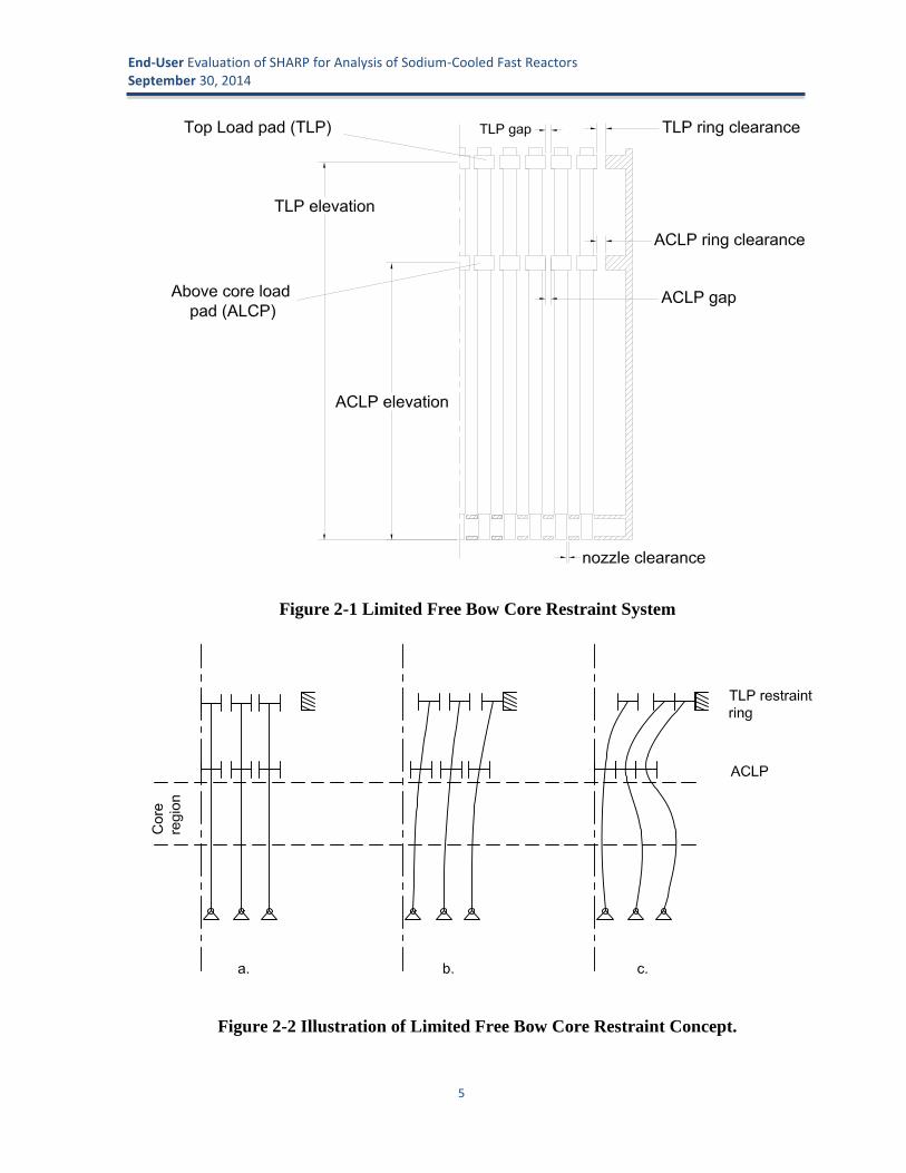
to induce limited free bow [17]. The restraint system is characterized by top load pads (TLPs) onthe assembly ducts at the top and above-core load pads (ACLPs) in the region above the core,along with restraining rings at the TLP and ACLP axial heights. The rigid restraint rings areattached to the core barrel at the ACLP and TLP locations. The load pads serve as preferentialcontact points between the ducts. The load pads add only marginal thickness to the main ductbody but they are nonetheless thick enough to maintain the desired form under the designloadings. The limited free bow core restraint system is designed to provide inherent protectionagainst over power events by taking advantage of thermally induced bending action of the fuelducts. This is illustrated in Figure 2-2 which shows a row of three cantilevered ducts locatedsymmetrically about the center of a core and in a radially varying thermal gradient.
End-User Evaluation of SHARP for Analysis of Sodium-Cooled Fast ReactorsSeptember 30, 2014
5
Figure 2-1 Limited Free Bow Core Restraint System
Figure 2-2 Illustration of Limited Free Bow Core Restraint Concept.

End-User Evaluation of SHARP for Analysis of Sodium-Cooled Fast ReactorsSeptember 30, 2014
6
Figure 2-2a shows the nominal configuration of the ducts with no temperature gradient. Asthe radial thermal gradient develops (increasing temperature as distance from centerlinedecreases), the ducts begin to bow outward as shown in Figure 2-2b. Prior to contact with the topcore restraint ring, the duct bends away from the core centerline as the temperature increases andtherefore reduces the reactivity insertion. After contacting the top restraint ring and as thetemperature gradient increases, the center of the duct bows inward which temporarily increasesthe reactivity. As the gradient increases, the inward bowing continues until the ducts contact atthe ACLP. When the interior ducts all contact at the ACLP, the reactor is ‘locked-up’ and nofurther compaction can occur. Subsequent increased thermal gradients cause a reverse bowingbelow the ACLP moving the core region away from the core center as illustrated in Figure 2-2c.At this point the reactivity generally decreases with constant negative slope as temperatureincreases. The core restraint system is designed to have this lock-up occur below the nominaloperating core outlet temperature.
For the specific problem of fast reactor core restraint design, ANL engineers use the NUBOWsoftware code which is a legacy fast reactor code developed at ANL in 1974 and updated atvarious points. The objectives of these NUBOW simulations are two ensure that the corerestraint system meets the following design objectives [17]:
1. Control core motion such that it is predictable and safe during transients and steadystage conditions. Reactivity insertion due to assembly bowing during transient over-power events must be negative, i.e. must help stabilize the core power.
2. Nominal refueling loads should be below a specified threshold.
3. Core alignment must be maintained to accommodate control rod movements.
4. Keep core assemblies within structural limits.
To accomplish this, NUBOW uses a characteristic fast reactor core description (number ofrows, duct dimensions, etc.) and then creates the model (mesh) and predicts the bowing motion ofthe assemblies using beam elements to model the duct. The analysis includes contact betweenducts and incorporates inelastic strains resulting from irradiation creep and swelling. As input,NUBOW uses core temperatures and flux distributions obtained from prior simulations of otherfast reactor physics analysis tools. To ensure negative reactivity feedback (objective #1 above),NUBOW includes a post-processing capability to evaluate the reactivity change that results frombowing of the duct assemblies using displacement reactivity worths as an input. Thesedisplacement reactivity worths are determined from a prior perturbation analysis with aneutronics code, and provided as input to NUBOW. This displacement reactivity worthcalculation procedure lacks a consistent set of best practices, the resulting reactivity estimatesmay also have significant uncertainty.
2.1.2 Modeling Safety PerformanceTo design an inherently safe fast reactor, reactivity dependence on radial core expansion must
be engineered into the reactor plant to assure a loss of reactivity during transient events. In theadvanced SFR concepts currently under consideration by the ART program, the core is designedto bow outward in response to thermal expansion of the structures in any transient where the coreis heating. The grid plate and load pads, which support the core from below and restrain it fromthe top, respectively, also expand outward. Moreover, the core restraint system is designed such

End-User Evaluation of SHARP for Analysis of Sodium-Cooled Fast ReactorsSeptember 30, 2014
7
that the fuel assemblies bow outward in the middle, further separating the fuel pins. Whencontrolled correctly, core expansion causes the fuel assemblies to move farther apart from eachother, which has a negative reactivity effect and helps to shut down the reactor. Simulation of thisexpansion, which is essential to the safety of these reactor concepts, necessitates the coupling ofstructural mechanics, thermal hydraulics, and structural mechanics.
For safety performance analyses supported by the ART program, the radial core expansionphenomena would typically be performed by a multi-step procedure. First, a neutronicsperturbation analysis would be performed. The approach here is to analyze the core under twoconditions—a reference condition and an expanded condition. The complex geometry of theexpanded core cannot be modeled by conventional deterministic neutronics codes; the postulatedexpansion must be uniform everywhere in the core. In fact, the expansion must be uniform bothradially and axially, i.e., all assemblies expand by the same amount, and the deformation does notvary along the length of the assembly. The perturbation analysis on this simplified geometryproduces either a single reactivity coefficient to represent the integral response of the core todeformation, or a set of reactivity coefficients to represent expansion along the length. Thesecoefficients are then employed in a separate transient analysis with the system codeSAS4A/SASSYS-1 [18]. The system code predicts the core temperature during the postulatedtransient scenario. SAS4A/SASSYS-1 has two models for predicting changes in radial coregeometry due to transient thermal expansion: the “simple” radial core expansion that assumes alinear function for the radial deflection, and the “detailed” radial core expansion model that treatsthe core as a single beam and permits a step-function axial profile for the radial deflection.Neither of the system code models are capable of modeling assembly bowing, but only includethe effect core flowering due to expansion of the load pads and the supporting grid plate.Neglecting assembly bowing should be a conservative approximation, as the prior core restraintdesign analysis (described above) should have indicated that the assembly bowing would be anegative contribution to the core reactivity.
2.2 The SHARP Multi-Physics Approach
2.2.1 Background on SHARPSHARP [1], developed under the NEAMS program, is an advanced modeling and simulation
toolkit for the analysis of nuclear reactors. SHARP is comprised of several components, includingphysical modeling tools, tools to integrate the physics codes for multi-physics analyses, and a setof tools to couple the codes within the MOAB [6] framework. Physics modules currently includethe PROTEUS [3] neutronics code, the Nek5000 [5] thermal-hydraulics code, and the Diablo [2]structural mechanics code. Development efforts in each of these physics modules were initiatedby other programs prior to NEAMS existence (although PROTEUS was quite immature), whichallows NEAMS to leverage prior investments. Nek5000 and Diablo were each originallydeveloped for other applications, with sponsorship from DOE Office of Science and the NNSA,respectively, each with 20-30 staff-years of investment. The development philosophy for thephysics modules is to incorporate as much fundamental physics as possible, rather thandeveloping tools for specific reactor analysis applications. This empowers designers to analyzetransformative reactor concepts with simulation tools that are not limited to availableexperimental data sets from currently existing reactor designs. By developing the tools to behighly efficient on parallel computing platforms, employing millions of processor cores,engineering-scale simulations become practical on high-performance computers currently

End-User Evaluation of SHARP for Analysis of Sodium-Cooled Fast ReactorsSeptember 30, 2014
8
available at the DOE complex. Because of this foundation of high-performance computing, theSHARP tools will grow increasingly practical, rather than increasingly obsolete, as computingpower continues to grow rapidly. Development efforts strive to work in tandem with efforts inexperimentation, so that the tools are validated to produce accurate results for modeling physicalphenomena that have been identified as important for nuclear reactor analysis. By taking thisapproach, SHARP supports nuclear reactor analysis and design activities for DOE programs andindustrial partnerships with trustworthy modeling and simulation tools.
PROTEUS is a high-fidelity deterministic neutron transport code based on the second-ordereven-parity formulation. The application scope targeted for PROTEUS ranges from thehomogenized assembly approaches prevalent in current reactor analysis methodologies to explicitgeometry approaches, with the ability to perform coupled calculations to thermal-hydraulics andstructural mechanics. The PROTEUS solver has a proven capability of using existing petascaleparallel machines to solve problems with demonstrated scalability of over 70% (strong scaling) atover 250,000 processors. These achievements of PROTEUS were made possible by partitioningthe space-angle system of equations over the available processors and utilizing establishediterative solution techniques from the neutron transport community combined with the parallelalgorithms in the PETSc toolbox.
The Nek5000 computational fluid dynamics solvers are based on the spectral element method.Nek5000 supports two different formulations for spatial and temporal discretization of theNavier-Stokes equations. The first is the PN-PN-2 method with velocity/pressure spaces based ontensor-product polynomials of degree N and N-2 respectively. The second is a low-Mach numberformulation that uses consistent order-N approximation spaces for both the velocity and pressure.The Nek5000 code has been extensively verified and validated for several benchmark problemsand has a proven scalability in existing petascale architectures up to 131,072 processors (over abillion degrees-of-freedom).The conjugate heat transfer problems that are typically present innuclear engineering applications can be solved rigorously using the formulations in Nek5000.
In order to perform thermofluid analyses of homogenized fuel assemblies for the coreexpansion problem, a porous media model was implemented in the Nek5000 code. Porous mediamodels are typically applied to problems where the fluid flows through a region with many small-scale solid structures, and it would be impractical to resolve the geometry explicitly. Instead, theeffect of the small-scale solid structures on the flow is modeled as a momentum sink or resistancein a homogenized fluid domain. In this particular case, we wish to model the influence of the fuelpins on the flow, i.e., drag and pressure drop, as a momentum sink without explicitly representingthe geometry of thousands of fuel pins. The model must also account for the energy depositionassociated with nuclear fission. Moreover, fuel and cladding temperatures are estimated for eachfuel assembly, and may be provided to the neutronics code in future coupled simulations. Thisenables prediction of the duct wall temperature profile, which controls the thermally-drivenstructural deformation in the core, with significantly lower computational expense than explicitrepresentation of the wire-wrap fuel bundle geometry.
The Diablo code being developed at Lawrence Livermore National Laboratory uses implicit,Lagrangian finite-element methods (FEM) for the simulation of solid mechanics and multi-physics events over moderate to long time frames. A primary focus is nonlinear structuralmechanics and heat transfer. The code provides a venue for applying parallel computation todiscretization technologies developed and user-tested in the legacy serial-processor codesNIKE3D and TOPAZ3D. Diablo is built around Fortran 95 data structure objects and a message-

End-User Evaluation of SHARP for Analysis of Sodium-Cooled Fast ReactorsSeptember 30, 2014
9
passing programming model. The architecture provides flexibility for the addition of other fieldproblems, such as electromagnetics.
In structural analysis of mechanical assemblies, a key functionality is "contact": capturing theinteraction between unbonded material interfaces. The Diablo team has broad experience withcontact problems and has created state-of-the-art algorithms for their solution. Their experiencewith contact motivates the use of low-order spatial discretizations, such as eight-node hexahedrafor continua and four-node quadrilaterals for shells. Appropriate formulations are employed toaccommodate nearly incompressible material models, such as for metal plasticity and rubberelasticity. Global algorithms include second-order and quasi-steady time integration and a numberof approaches for nonlinear iteration: full Newton, modified-Newton, multiple quasi-Newtonupdates, and line search. Linear solvers are utilized from multiple libraries.
2.2.2 The SHARP Model of Core DeformationThe details of the SHARP model of the core deformation of the ABTR core are described in
prior DOE reports [12, 13], and so are just summarized here. The simulations were preliminary,and were intended to demonstrate the capabilities of the SHARP codes to simulate complexmulti-physics response. The simulation could be considered to be a quasi-static analysis todetermine the initial geometry of the fresh core at the hot operating condition. Rather than goingthrough the complex time-dependent start-up procedure with the required control rod motion, thecore configuration is fixed as the inlet flow and power are at the nominal operating conditionsthroughout the simulation. The core power is fixed throughout, and the fission source is adjustedby keff (which deviates from unity). The strategy can be summarized as follows:
1. At each global iteration of the three physics (SHARP Global iteration), the mesh isupdated and the input files are modified with corrected densities.
2. As part of each global iteration, 50 inner iterations are performed between PROTEUS andNek5000 to converge the neutronics and thermal-hydraulics fields.
The full core ABTR problem has 199 assemblies in total, including 60 fuel assemblies. Thetotal power is set to 250 MWt based on the specification. The fuel assemblies comprise threedifferent types: inner core, outer core, and fuel test assemblies, which differ only by fuelcomposition.
The full core mesh for PROTEUS has 825k vertices and nearly 800k elements. Combinedwith 48 modeled angles in PROTEUS and 9 energy groups, the neutronics model has 356.5million space-angle-energy degrees of freedom. The Nek5000 mesh employs the same 800kquadratic elements with a polynomial order of N=2. The Diablo mesh includes only the solidducts, load pads, and restraint rings, because the contribution of the fuel pins to resistingstructural deformation is negligible. Both the PROTEUS neutronics and Nek5000 thermal-hydraulics models treat the interior of the fuel assembly—which includes the fuel pins andinterstitial coolant—as a homogenized media, with Nek5000 employing the porous mediummodel. Bypass flow between adjacent assemblies is not treated; rather, these regions arerepresented by solids.
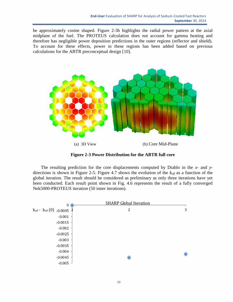
Figure 2-3 depicts the power distribution in the fuel assemblies of the full-core ABTR modelfrom the initial PROTEUS simulation. Figure 2-3a in particular shows the 3D distribution in theentire active core region sectioned along the core centerline to expose interior features. The powerdistribution is peaked at the radial and axial center of the core, and the z-dependence appears to
End-User Evaluation of SHARP for Analysis of Sodium-Cooled Fast ReactorsSeptember 30, 2014
10
be approximately cosine shaped. Figure 2-3b highlights the radial power pattern at the axialmidplane of the fuel. The PROTEUS calculation does not account for gamma heating andtherefore has negligible power deposition predictions in the outer regions (reflector and shield).To account for these effects, power in these regions has been added based on previouscalculations for the ABTR preconceptual design [10].
(a) 3D View (b) Core Mid-Plane
Figure 2-3 Power Distribution for the ABTR full core
The resulting prediction for the core displacements computed by Diablo in the x- and y-directions is shown in Figure 2-5. Figure 4.7 shows the evolution of the keff as a function of theglobal iteration. The result should be considered as preliminary as only three iterations have yetbeen conducted. Each result point shown in Fig. 4.6 represents the result of a fully convergedNek5000-PROTEUS iteration (50 inner iterations).
keff - - keff (0) SHARP Global Iteration

End-User Evaluation of SHARP for Analysis of Sodium-Cooled Fast ReactorsSeptember 30, 2014
11
Figure 2-4 keff as a Function of the Global Iteration
Figure 2-5 Magnified (100x) Displacements Colored by the Displacement in the y-direction
2.3 Evaluation of the SHARP Team’s Multi-Physics DemonstrationART end-users had the opportunity to evaluate the effort by the SHARP team to perform a
preliminary demonstration of the capability to treat the combined neutronics, thermal-hydraulics,and structural mechanics effects as an SFR core undergoes structural deformation induced bythermal gradients. This was a successful demonstration that shows a unique modeling capabilitythat, after some additional development efforts and a verification and validation campaign, couldbe employed to ensure SFR safety performance while avoiding expensive and exotic safetysystems. A list of additional considerations and necessary improvements to SHARP include:
PROTEUS lacks the capability to predict photon transport, and the simulationsassumed a gamma heating rate that came from a separate calculation by a conventionalcode. These off-line simulations for gamma heating are not consistent with the fissionrate predicted by PROTEUS, which in turn are dependent on the thermal-hydraulicsand geometry conditions predicted by Nek5000 and Diablo. The capability to predictphoton transport and the corresponding gamma heating directly in PROTEUS wouldbe more accurate and avoid the need for off-line simulations.
The SHARP simulations were quasi-static, which would be useful to support corerestraint design applications, as described in Section 2.1.1. However, in order tosupport safety analysis (see Section 2.1.2), the simulations would need to be time-dependent. A time-dependent capability requires a significant development effort in

End-User Evaluation of SHARP for Analysis of Sodium-Cooled Fast ReactorsSeptember 30, 2014
12
PROTEUS, which includes only an adiabatic kinetics feature, and improved quasi-static is likely necessary. In any case, the transient multi-physics capability has not yetbeen demonstrated with all three physics modules.
During the demonstration simulation, if a particular duct deforms such that the fuelassembly volume increases, the mass of solid materials within the homogeneousregions in PROTEUS is conserved by reducing the density. During the density update,it is assumed that the volume of each fuel pin is fixed to their initial values, andsodium coolant rushes in to fill gaps caused by the increased volume. However, thefuel pins would also swell and lengthen under thermal gradients, thus changing therelative volume occupied by solid and coolant. A model for this should be included inthese density updates.
In the SHARP simulations, the focus was on core structural deformation associatedwith assembly bowing and grid plate expansion, which is controlled by the motion ofthe subassembly duct walls. However, the fuel pins also lengthen vertically,effectively changing the shape of the core. This motion is independent of the ductmotion, and is controlled by the thermo-mechanical properties of fuel and cladding,and their associated temperature changes. This is currently accounted for inSAS4A/SASSYS-1 as a distinct reactivity feedback mechanism referred to as axialexpansion. This should also be accounted for in the SHARP simulations, either byadjusting the geometry directly or by another adjustment during the density updateprocess mentioned previously.
Fuel Doppler feedback—associated with the strong temperature dependence of thefuel absorption rate in fuel isotopes—was not accounted for during the SHARPsimulations. There is a capability in PROTEUS to adjust the fuel isotope temperaturesin homogenized regions, but it needs to be exercised in the context of thesesimulations.
The spatial mesh for all three physics modules was relatively coarse, as the objectivewas for demonstration rather than validation. Further work should be performed toprovide simulations for a spatially-converged mesh, which would also provide insightinto the computational expense of running these simulations and test the RGG meshgeneration tool.
The calculation procedure for performing multi-physics SHARP simulations,especially with the structural mechanics code Diablo, is still rather complex and is notautomated. In fact only a couple of members of the SHARP team have proven able tomanage the simulation process. Now that the demonstration has been performed, theprocedure needs to be automated and new staff (on both the SHARP and ART teams)need to be trained.
The majority of these items were already described in the SHARP team’s reports [12, 13], anddiscussions between the SHARP developers and ART engineers have been ongoing.

End-User Evaluation of SHARP for Analysis of Sodium-Cooled Fast ReactorsSeptember 30, 2014
13
3 Evaluation of SHARP Neutronics (PROTEUS)PROTEUS is a three-dimensional neutron transport code targeted for nuclear reactor
applications. It can be utilized for both stand-alone neutronics analysis and coupled SHARPsimulations. It is highly scalable, and is particularly applicable in situations where a high degreeof fidelity is needed to resolve solution gradients or capture spatial details [4].
3.1 Analysis of EBR-II with PROTEUSIn order to fully evaluate PROTEUS, technical efforts were also made to use the code.
PROTEUS was first used to simulate a series of benchmark problems. For a more detailedevaluation, the code was then used to model the Experimental Breeder Reactor II (EBR-II). Theresults described in this section should be considered preliminary; the purpose was to learn to usePROTEUS rather than to perform a thorough investigation.
EBR-II is a heterogeneous, sodium-cooled fast breeder reactor which operated from 1964 to1994. The PROTEUS model of EBR-II was built based on equivalent MCNP and DIF3D modelscreated in support of the SHRT-45R test neutronics benchmark analysis [19]. The particular coreloading in these models corresponds to EBR-II run 138B.
Two types of driver subassemblies were used in this core loading. In addition to the driversubassemblies, the central region of the core also contained control, safety, and dummysubassemblies. Select locations contained experimental subassemblies. Reflector subassembliessurrounded the central core region, and these were in turn surrounded by a depleted uranium outerblanket. The entire core configuration was enclosed in a sodium pool. The driver and blanketsubassemblies were partially depleted prior to this run. Therefore, each subassembly had a uniquecomposition. However, in the particular DIF3D and MCNP models considered in this analysis,subassemblies of a common type were all modeled with the same composition, which was anaveraged composition excluding fission products. This approach was also taken in the PROTEUSmodel, in order to perform code-to-code comparisons.
The mesh for the PROTEUS simulation was created using the recently-developed meshingtool Reactor Geometry Generator (RGG) [7]. This therefore allowed for further evaluation ofRGG as well. Meshes of the unique subassembly types were first created using the RGG utilityAssyGen. Each of these sixteen subassemblies was homogenized radially, but axial heterogeneitywas preserved. In order for the different subassemblies to merge in the eventual full-core model,it was necessary to apply the same axial meshing scheme in all subassemblies. Each subassemblytherefore has an axial segmentation at each elevation where any subassembly type has a change inmaterial. Radially the subassemblies were meshed with four segments per edge, which wasspecified using the EdgeInterval variable. . Examples are shown in Figure 3-1. All subassemblieswere constructed with “CreateSideset=No” to prevent internal sidesets in the final core model.

End-User Evaluation of SHARP for Analysis of Sodium-Cooled Fast ReactorsSeptember 30, 2014
14
(a) (b)
Figure 3-1 Examples of the PROTEUS EBR-II Assembly Mesh, (a) Axial Mesh andMaterial Regions and (b) Radial Mesh
The full core mesh was constructed from the individual assemblies using RGG’s CoreGenutility. The top, bottom, and collective radial sides were each assigned a sideset value, which isnecessary to specify boundary conditions in PROTEUS. Coregen produced a .h5m mesh file,which is compatible with MOAB-enabled PROTEUS. However, because this version of the codeis not currently stable, the file was instead converted for use with stand-alone PROTEUS. First,the mesh was converted to the CUBIT [20] exodus file format (.exo, .e) using the MOABmbconvert utility. This exodus file was then converted to a PROTEUS-compatible .ascii mesh fileusing a utility recently created by the PROTEUS development team. The EBR-II meshconstructed for PROTEUS simulations is illustrated in Figure 3-2.

End-User Evaluation of SHARP for Analysis of Sodium-Cooled Fast ReactorsSeptember 30, 2014
15
Figure 3-2 PROTEUS Full-Core EBR-II Mesh
The PROTEUS simulations used the ISOTXS cross-section file already developed for simulationof the DIF3D EBR-II model. This file was created using the MC2-3 code, with the ANL33 energygroup structure [21].
The EBR-II material compositions were first assigned to the appropriate geometric regions inthe individual RGG assembly input files. Because the MCNP text input is simpler to follow thanthe DIF3D input, this was done based on the information in the MCNP input file, and the MCNPmaterial numbers were used as the RGG material names. The cross-section file uses the DIF3Dmodel’s isotope naming scheme, so the actual composition information for the PROTEUSassignment file was later extracted from the EBRII DIF3D input.

End-User Evaluation of SHARP for Analysis of Sodium-Cooled Fast ReactorsSeptember 30, 2014
16
Although the material information was provided in the RGG inputs to generate the mesh,there is not a currently an automated way to provide this information to PROTEUS. PROTEUSrequires material specifications via a text (.assignment) file which specifies the material in eachregion of the mesh, and provides material properties such as density. The isotopic naming schemeused in this file must match the naming scheme used in the creation of the ISOTXS file.
To create the EBR-II assignment file, a simple python script was developed. To determine theisotopic compositions and total density of each material, the script read the DIF3D input file andextracted this information. The script contained definitions connecting the MCNP compositionnames (which were used in the RGG input files) with the composition names in the DIF3D file. Itthen read the individual RGG assembly files, determined what the eventual mesh file regionnumbers will be based on the starting values specified by the MaterialSet_StartId variable, andthen linked each region number to its composition (and corresponding density and isotopeconstituents). Finally, the script wrote all of this information to a text file in the PROTEUSassignment file format. The fixed structure of the RGG input files made it very simple to do this.Essentially, each region number can be predicted because they will be named based onincremental additions to the MaterialSet_StartId value, with a new region beginning anytimethere is a change in the material specification. For example, if an AssyGen input has sevendifferent materials axially, and MaterialSet_StartId is 201, the seven regions in the resultant meshfile will be regions 201-207. This basic logic could be utilized to develop a more universal toolfor creating a PROTEUS assignment file from RGG inputs.
Simulation of the EBR-II model proved difficult because of the high computing demands ofPROTEUS. After failed attempts to simulate the model on smaller machines, it was necessary toobtain an account on one of ANL’s Advanced Leadership Computer Facility (ALCF)supercomputers. The model was then simulated using Legendre-Tchebychev cubature, for variousresolutions in angle. The results were evaluated and compared to simulations of the MCNP andDIF3D models. Example results are shown in Table 3-1,Figure 3-3 and Figure 3-4.
Table 3-1 Calculated Eigenvalue of the EBR-II SHRT-45 Run 138B Core Loading(Preliminary Results)
k-eff ρ (pcm)
Differencefrom
MCNP(pcm)
Differencefrom
DIF3D(pcm)
MCNP 0.99501 ± 0.00016 -501.5-755.1
DIF3D 0.98759 -1256.6
PROTEUSL1T1 0.97477 -2588.0 -2086.5 -1331.4L5T5 0.97737 -2315.1 -1813.6 -1058.5
L7T23 0.97744 -2308.2 -1806.7 -1051.6

End-User Evaluation of SHARP for Analysis of Sodium-Cooled Fast ReactorsSeptember 30, 2014
17
(a) (b)
Figure 3-3 Power Distribution in the EBR-II Core at 55% Core Height, (a) DIF3D and (b)PROTEUS (Preliminary Results)
(a) (b)
Figure 3-4 Group 8 (E = 302-498 keV) Flux Distribution in the EBR-II Core at 55% CoreHeight, (a) DIF3D and (b) PROTEUS (Preliminary Results)
It is expected that the PROTEUS results would be in better agreement with the other codes ifthe simulation were repeated with a more refined mesh. According to the code developers,PROTEUS cannot determine an accurate eigenvalue without a good solution spatially. However,since the focus of this analysis was evaluation of the code’s usability (rather than a technicalstudy of EBR-II), additional simulations were not pursued at this time. The results should beconsidered preliminary.
3.2 Feedback on Utility of PROTEUS for Reactor Analysis NeedsThe evaluation of PROTEUS has considered how well the code can meet current needs of
users, as well as general usability. The current code documentation has also been considered,since documentation plays an important role in usability.

End-User Evaluation of SHARP for Analysis of Sodium-Cooled Fast ReactorsSeptember 30, 2014
18
3.2.1 Ability to Meet User NeedsAs discussed in Section 2, PROTEUS is uniquely suitable for evaluating complex multi-
physics problems such as radial core expansion, because the code is very flexible in the mesh itcan use. This flexibility also benefits standalone PROTEUS users. It allows for explicit modelingof unique geometries, such as reactors with unconventional fuel designs or reactors with an in-core experiment sample, which many other codes (other than Monte-Carlo codes) cannot handle.
PROTEUS’s role within the SHARP multiphysics analysis toolkit is also very beneficial topotential users. Using standalone neutronics and thermal codes often requires a great deal ofwork, since the output from one code must be manually translated into the information needed bythe other code. Having an automated method of doing this within the framework of the coupledSHARP package will save users a great deal of time.
As mentioned in Section 2, PROTEUS lacks a photon transport model and is limited to onlyan adiabatic model for neutron kinetics. Both photon transport and advanced neutron kineticsmodels would be useful for standalone neutronics simulations, as well as the previouslymentioned multiphysics problems. . Although gamma heating can be approximated with a fixedvalue, there are other instances where users may be interested more specific information, such asestimating the flux at some detector location. Many users would also benefit from theimplementation of more advanced time-dependent simulation capabilities. The current adiabaticapproximation is more accurate than point kinetics, but not as accurate as improved quasi-static orfull kinetics methods.
Recently, the code developers have introduced a cross-section API, which allows for on-the-fly processing of cross-sections for the exact true reactor geometry. Verification of this utility isnot yet completed. This new feature offers benefit to users, both from the ability to use the truegeometry and from the fact that it eliminates the need to also construct an MC2-3 model for cross-section generation. Both the PROTEUS cross-section API and MC2-3 are only equipped to useENDF-VII cross-sections; in the future, it could be beneficial to users if they also had the optionto use other sets of evaluated nuclear data, such as the JEFF or JENDL libraries.
Another area of interest to potential users is the ability to perform burnup calculations.Currently, analysts can evaluate total core burnup with DIF3D/REBUS, but this does not providedetailed information. If PROTEUS were coupled with a depletion code, users could examine howthe detailed flux profile affects burnup (similar to Monte-Carlo coupled codes, such as MCODE[22]). According to the PROTEUS developers, ORNL has initiated work to create an API forORIGEN within PROTEUS, but it was not evaluated here because the effort is very recent.
PROTEUS provides a text output, which contains the final eigenvalue, and a VisIt-compatibleHDF5 file [8]. The HDF5 file contains the full solution, which allows users to evaluate detailedresults such as the power distribution within a single fuel pin. This degree of detail is beneficial tousers who are interested in in-depth analysis of the complex behavior of a reactor core. However,in many instances users frequently want to report integral parameters, such as power peakingfactors, for simple comparison of reactor designs. There is not currently code structure in place tofacilitate such integration of the solution data. PROTEUS does have a recently-developedfunction which allows users to average solution data over regions, i.e. a collection of finiteelements with the same material assigned. Depending on how these regions are defined by theuser, these averages may not be particularly useful. For instance, the user may assign segments ofdifferent fuel pins to the same region, in order to save effort generating the material assignment

End-User Evaluation of SHARP for Analysis of Sodium-Cooled Fast ReactorsSeptember 30, 2014
19
file. In this case, it would be impossible to use the region-averaging feature to calculate the pinpower distribution. Similarly, fuel assembly averages could not be produced directly. Onepossible solution would be to develop a utility that works with RGG to recognize common unitslike pins and assemblies. It may be very difficult, however, to develop a universal utility fordetermining this information for models that were not created with RGG. Because PROTEUSdoes provide a very detailed solution, it would be good if the user also had flexibility in the waythey average the result data. For example in MCNP, a user can request results for a region as awhole, or they can apply any degree of radial and axial segmentation for more detailedinformation [23]. VisIt has some capability to integrate results over user-defined regions, but thiscapability is not currently fully functional with the PROTEUS HDF5 file (the data can only beintegrated over complete PROTEUS regions, as mentioned above, but not over any subset of aregion). If this functionality were added, users could manually evaluate parameters such as powerpeaking factors for any model. In conclusion, it is recommended that a tool for determining powerpeaking factors is developed for RGG-created models, and that the ability to integrate resultquantities over any region is developed for all models (either via VisIt, or via some other utility).
3.2.2 DocumentationPROTEUS documentation includes both a User’s Manual and a Methodology Manual [3, 4].
This robust documentation does a very good job of providing necessary information to users.However, it would be helpful if the documentation provided a little more guidance on practicalcode use. It is not possible to provide fixed rules, but examples would help users to make moreinformed decisions in their own simulations, which could save them a great deal of time. Two keyareas where examples could be helpful are (1) the computing power necessary and (2) thesolution accuracy achieved, for full core simulations of models with various degrees ofrefinement in the mesh, the solution cubature, and the cross-section library energy structure. Thistype of information is something that could naturally evolve out of the future code verificationand validation work.
While stand-alone usage of PROTEUS is well documented, the documentation provides littleinformation on PROTEUS in relation to the other SHARP codes. For example, to create aPROTEUS model with RGG, a particular flag must be turned on to avoid creating internalsidesets (i.e. boundaries) between adjacent assemblies. However, neither the RGG nor PROTEUSdocumentation explicitly states that this flag must be used to create a model for PROTEUS. Inaddition, there is little information on PROTEUS’s role within SHARP coupled simulations. Itwould be very useful for the code documentation to discuss things such as, for example, theinformation that PROTEUS passes to the other SHARP physics codes. This could beaccomplished by additions to the PROTEUS documentation, or by the creation of a new manualon SHARP coupling.
It would also be useful for the manual to provide more discussion on the other codes that mostPROTEUS users will be using, such as MC2-3, CUBIT and VisIt. These codes of course havetheir own manuals, but if there is any information that could help facilitate the intelligent use ofthese codes for PROTEUS in particular, this would be helpful for users. In particular, this wouldbe beneficial to new users who have no experience with any of these codes.

End-User Evaluation of SHARP for Analysis of Sodium-Cooled Fast ReactorsSeptember 30, 2014
20
3.2.3 General UsabilityTo perform a PROTEUS simulation, there are four input files required (with supplemental
files needed for kinetics jobs, fixed source problems, and parallel runs). The main input files aredriver (.inp) file, which controls the PROTEUS calculation and also points to the other input files,a mesh file (.nemesh or .ascii for serial execution), an assignment (.assignment) file which placesmaterials in the geometric regions and provides material properties, and a cross-section (binary.ISOTXS or ASCII .anlxs file). These files are each developed individually, but the informationcontained in them must be compatible.
Reactor analysts want to spend their time focusing on the physics of a problem, rather than onbuilding simulation inputs. Currently, it can be time-consuming to generate the full set of inputsnecessary to evaluate a problem with PROTEUS. In addition, it is necessary to learn other codesin order to generate the mesh and cross-sections for a PROTEUS simulation (although the lattercould change after the PROTEUS cross-section API is verified).
The SHARP toolkits RGG and NiCE are being developed to help address these issues. RGGoffers a method in which full-core three-dimensional meshes can be generated using simple text-based inputs, while NiCE will provide other utilities to facilitate input file creation and resultanalysis. Both of these toolkits will serve to make PROTEUS more user-friendly, particularly fornew users or users analyzing standard PWR and SFR geometries.
The quality of the documentation, as discussed above, also helps to make PROTEUS moreuser-friendly. Having detailed documentation makes it easier for analysts to use the code.PROTEUS also appears to have good error checks in place, which similarly is very helpful.
In general, the high computing demands of the code may limit the potential user base. Forexample, in the EBR-II analysis discussed above, it was necessary to obtain an account on one ofthe supercomputers in order to run the simulation. And this was for a mesh that was still toocoarse to obtain a good solution; for improved accuracy the model would have to be run with afiner mesh (which would require even more processors). Many potential users do not have accessto this kind of computing power.
Currently the biggest impediment to using PROTEUS is the fact that the code has not hadsufficient testing and development to be considered a production level tool. Because of this, thePROTEUS manual includes a disclaimer which states that the reliability of the code is notguaranteed. Furthermore, PROTEUS’s accuracy has not been evaluated for a wide range ofreactor physics problems. Without question, validation and verification are the biggest priorityneeds for PROTEUS. Difficulties in code use can be managed, but code reliability is essential.
The manual disclaimer also states that “In many cases, performance and efficiency have beensacrificed in favor of providing a working capability which prevents one from making a realisticcomputational effort comparison to other available tools. In many cases, reliable algorithms havebeen chosen to compensate for memory shortages on high performance computing machineswhich degrade the wall clock performance of the existing code”. If there are steps the codedevelopers could take to improve the performance and efficiency of the code, without sacrificingany of the current capabilities, these efforts should be pursued.
The PROTEUS developers were very helpful throughout the code evaluation. They providedinstruction and feedback, and also made efforts to assist whenever possible. To facilitate theEBR-II analysis, they installed PROTEUS on additional machines, and then assisted in getting an

End-User Evaluation of SHARP for Analysis of Sodium-Cooled Fast ReactorsSeptember 30, 2014
21
ALCF account when it became clear that the ANL Nuclear Engineering Division machines wouldnot be sufficient. The code developers also addressed issues very quickly. For example, whencode errors were identified during the EBR-II analysis, they made the necessary corrections to thecode the same day.
3.3 ART’s Requirements for PROTEUSPROTEUS offers numerous advantages, including the ability to model unconventional
geometries and the multiphysics analysis potential provided by its role within SHARP. However,there are areas where additional work should be done to improve PROTEUS for users. Theseinclude:
Perform additional verification & validation as needed to ensure the accuracy ofPROTEUS.
Where possible, make changes to the code structure to improve performance andefficiency.
Provide additional examples to give users a better guide for intelligent code use.
o Computing power needed for different refinements in space, angle, and energy
o Solution accuracy with different refinements in space, angle, and energy, and withdifferent solution options.
Resolve issues with VisIt file so users can integrate quantities over any region (or developalternate utilities to do this).
Develop utilities to determine common parameters of interest like power peaking factors.
Expand the PROTEUS documentation to include discussions on PROTEUS in the contextof the other SHARP codes – requirements for creating a PROTEUS model with RGG,explanation of PROTEUS coupling with NEK and Diablo, etc.
Expand the documentation to include discussions on the intelligent use of MC2-3, CUBIT,VisIt, and any other supporting software, in the context of their role in PROTEUSsimulations.
Continue verification of the cross-section API (and potentially implement the ability touse cross-section libraries other than ENDF-VII).
Implement photon transport.
Improve PROTEUS’s time-dependent simulation capabilities.
Couple PROTEUS to a depletion code for burnup calculations.

End-User Evaluation of SHARP for Analysis of Sodium-Cooled Fast ReactorsSeptember 30, 2014
22
4 SHARP Thermal-Hydraulics (Nek5000)
4.1 Overview of Ongoing Application of Nek5000 to Reactor AnalysisThe Nek5000 code is actively being used to analyze hydraulics and conjugate heat transfer in
SFRs for problems of interest to ART. Nek5000 Large Eddy Simulations (LES) of coolant flowin SFR bundles has been demonstrated to be scalable up to 65,000 processors [5], providing asource of validation for RANS modelling [24] and providing physical insight into complex flowphenomena such as the hot spots that may develop due to flow stagnation near the contact pointof the wire-wrap and fuel pin [25].
Nek5000 is being used to analyze the JAEA sodium jet mixing experiment PLAJEST underan ART-supported collaboration with CEA and JAEA. The objective of this exercise is to validateNek5000 for the prediction of thermal fluctuations in sodium that may result in thermal stripingand fatigue in structural materials in SFRs. Preliminary results were presented in a prior report[26], and sample results are provided in Figure 4.1. The Large Eddy Simulations shown in Figure4.1 were performed by a member of the Nek5000 development team, although future work isbeing planned that will include contributions from a nuclear engineer whose training wassupported by this project.
Figure 4-1 Model (left) and Velocity Predictions (right) for the PLAJEST Benchmark(Preliminary Results)
In addition, two-phase boiling models are being implemented in Nek5000 for analysis ofLWR core thermal-hydraulics in an effort supported by another program. One of the co-authors ofthis report received training in Nek5000 and is working with the development team to implementtwo-phase flow models into Nek5000. Nek5000 was originally developed to modelincompressible flows, and so a simple homogeneous flow solver is being implemented as a first

End-User Evaluation of SHARP for Analysis of Sodium-Cooled Fast ReactorsSeptember 30, 2014
23
step to modeling boiling. The main assumption of this homogeneous model is relative velocity ofthe two phases, i.e, water and vapor, is negligible. It is well known that the assumption ofhomogeneous flow is insufficient to describe LWR core channel thermal-hydraulics. Thus, theinitial exercise of implementing the homogeneous flow model is intended to evaluate methodsand numerical development issues without the complexity of developing more sophisticatedmodels. As an example of the results of the new capability in Nek5000, some simulations of avertical heated pipe experiment [27] are presented Figure 4-2 with preliminary comparisons tomeasured wall temperatures in Figure 4-3. The model predicts dryout occurring at a significantlylower elevation in the pipe, and does not capture the rapid temperature rise correctly. These errorscan be attributed to known deficiencies in the homogeneous flow model, and will be improved infuture work by implementing more sophisticated drift flux and two-fluid models.
Figure 4-2 Contour Plot of Predicted (i) Temperature, (ii) Vapor volume fraction and (iii)Velocity Magnitude Profile of Heated Flow in a Vertical Pipe (Preliminary Results)

End-User Evaluation of SHARP for Analysis of Sodium-Cooled Fast ReactorsSeptember 30, 2014
24
550
600
650
700
750
800
0 1 2 3 4 5 6 7
Wal
l Tem
pera
ture
[K]
Tube Length [m]
Homogeneous Model
Becker Experiment
Figure 4-3 Comparison of Experimental Measurements to Nek5000 Predictions using theHomogeneous Flow Model (Preliminary Results)
4.2 Feedback on Utility of Nek5000 for Reactor Analysis NeedsFor the important problem of structural deformation of an SFR core, Nek5000 provides a
unique thermal-hydraulics modeling capability when coupled in the SHARP framework toPROTEUS and Diablo. In this regard, Nek5000 provides ART with a very useful resource formodeling and simulation.
For other thermal-hydraulic design and safety performance analysis applications, Nek5000 isone of several tools available to ART engineers. Other commonly used tools include thecommercial CFD code STAR-CCM+ [28] for general flow and heat transfer applications, andArgonne’s liquid-metal reactor safety systems code SAS4A/SASSYS-1 [18] for channel thermal-hydraulics and a variety of other physics modeling for SFR safety performance.SAS4A/SASSYS-1 includes a sub-channel model to compute steady-state and transient fuel,cladding and coolant temperatures in each fuel pin and coolant sub-channel of a subassembly,which was validated using the measured temperatures in the special instrumented subassemblyXX09 in the Experimental Breeder Reactor-II during the Shutdown Heat Removal Test-17 [29].STAR-CCM+, which is primarily used with its steady or unsteady Reynolds-Averaged Navier-Stokes (RANS) turbulence modelling options, has been used in a variety of SFR pin bundleanalyses. Some of this analysis work was motivated by a study of a particular 217-pin bundlesimulation where an interesting phenomenon was observed: RANS predicted a periodicity in thepredicted coolant temperature profile induced by the wire-wrap, which cannot be predicted by thecurrent SAS4A/SASSYS-1 sub-channel model. Such studies can now be used in to improve sub-channel models [30]. Other applications include a study comparing spacer grid and wire-wrapoptions [31].

End-User Evaluation of SHARP for Analysis of Sodium-Cooled Fast ReactorsSeptember 30, 2014
25
Nek5000 provides the highest level of fidelity in the set of available tools, as it includesDirect Numerical Simulation and Large Eddy Simulation (LES) of turbulent flows coupled toconjugate heat transfer models. The LES capability has been shown to reproduce measured datawith a high level of accuracy for several relevant applications, including heat transfer inelectrically heated rod bundles [32] and turbulent jet mixing [33,34]. Because Nek5000predictions have been demonstrated to be so reliable, ART engineers would be able to use it toreduce the number of experiments required to test designs (e.g. for pressure tests of subassemblyinlets) and to perhaps to push designs into regions where predictions by other codes have highuncertainty, e.g. for situations with flow instabilities or flows that are not fully developed.However, one immediate use of Nek5000 would be to provide additional validation points (inaddition to experimental datasets) that can provide validation to the lower-order methods whichcan then perform the routine design analysis. This approach keeps the computational expensereasonable, while still providing a high level of confidence in code predictions. Past experienceshave shown, e.g. for the MATIS benchmark, that the commercial code STAR-CCM+ can be usedeffectively after selecting turbulence modeling options based on predictions from prior Nek5000simulations.
Furthermore, the NEAMS team is currently working to provide a flexible modeling capabilityin the Nek5000 code, so that it can provide several levels of modeling fidelity itself. Developmentof an unsteady Reynolds-Averaged Navier Stokes (URANS) turbulence model is underway,which will significantly reduce the computational burden of high-resolution simulations byemploying more approximate models for turbulence. For the multi-physics demonstrationproblem, a porous media modeling capability was developed, which is a much faster but lower-fidelity model that homogenizes geometric detail.
Because Nek5000 is an open-source code and code developers are available at Argonne, thereare no barriers to updating the code as ART’s modeling needs require. This advantage wasdemonstrated during the core structural deformation exercise: the demonstration required a faster-running model, and the porous media model was implemented in a matter of weeks.
Nek5000’s success at performing well on extreme scale computers will enable it to performlarge-scale simulations that are impractical if not impossible to perform with commercial toolslike STAR-CCM+. The parallel algorithms used by such commercial tools impose an upper limiton the number of parallel processes that can be executed efficiently. In fact, based on experiencewith other programs, the commercial tools have other limits on the number of mesh that can begenerated, even with more than sufficient physical memory on the computing workstation. Forsuch problems, Nek5000 becomes the more practical option, with less time required for thesimulation.
Although the exercise of implementing two-phase boiling models in Nek5000 is not directlyrelevant to SFR analysis needs in the near term, it does demonstrate that the Nek5000 code can belearned by new users who can make substantive code development in a relatively short period oftime. Thus we anticipate that Nek5000 can continue to be used and further developed byengineers who are already supporting the ART program.
While the physical modeling capability and parallel scaling provide unique advantages forNek5000 for ART’s modeling and simulation needs, commercial tools will continue to be usedfor routine analyses for the foreseeable future. Commercial vendors provide documentation, meshgeneration tools, post-processing tools, and dedicated technical support that can never be

End-User Evaluation of SHARP for Analysis of Sodium-Cooled Fast ReactorsSeptember 30, 2014
26
practically matched by tools developed in the Lab system. These tools enhance user productivity,so for moderately-sized problems where commercial tools like STAR-CCM+ can be used withconfidence, they will continue to be preferred.
4.3 ART’s Requirements for Nek5000There are several areas in which the NEAMS program could support further development to
make Nek5000 a more appealing tool, including:
The computational expense of Large Eddy Simulations is often significantly greater thanthe RANS techniques offered by commercial tools like STAR-CCM+. The continueddevelopment of the unsteady RANS capability in Nek5000 would enhance its appeal toART’s needs.
Although Nek5000 has already performed several successful validation exercises withcomparisons against measured data, the validation effort must continue to provideconfidence in its capability to model important thermal-hydraulic phenomena in sodium-cooled fast reactors, such as buoyancy-driven flow, conjugate heat transfer, turbulentmixing, and heat transfer in liquid metals. Nek5000’s primary advantage over commercialCFD tools is its potentially more accurate solution, so demonstrating and documentingthis capability is essential to meet quality assurance requirements for nuclear reactoranalysis.
The documentation available for Nek5000 is actually based on a commercial product(Nekton) that precedes Nek5000, and some additional documents that describe additionalfeatures. However, the documentation is not a complete and coherent document, whichimposes a barrier to its adoption.
Nek5000 has stricter mesh requirements than most commercial CFD tools, i.e. allelements must be hexahedra, possibly with curved edges. Although such meshes mayproduce more accurate results, they are usually time-consuming for most analysts togenerate for complex geometries. The NEAMS team should respond with a plan forreducing this barrier to entry for Nek5000, e.g. by allowing more flexible meshing optionsin Nek5000, by furthering the development of MeshKit and RGG, or perhaps by workingwith commercial vendors for mesh generation to recommend tools to new Nek5000 users.
Boundary conditions are specified in a Fortran source file (userbc) routine and thus aresubject to user coding error each time this routine is touched, which may make satisfyingcode validation requirements difficult in the future. It is true that only the code setupscould be validated and, to be precise, only for a particular experiment setup or a class ofproblems. Perhaps additional parameters could be added to the user input file for caseswith simple boundary conditions, in order to reduce the number of models that require thedevelopment of user code and thus the number of associated user coding errors.

End-User Evaluation of SHARP for Analysis of Sodium-Cooled Fast ReactorsSeptember 30, 2014
27
5 SHARP Structural Mechanics (Diablo)
5.1 Application to Soil-Structure Interaction Analysis
5.1.1 IntroductionThe test problem chosen is to calculate the vertical impedance function of a massless square
footing on an elastic half-space in the time domain. The reason for choosing this test problem isthat it is a straightforward problem for a finite element method (FEM) analysis and the analyticalsolution is available for comparison. The impedance function is the dynamic force-displacementrelation between a massless foundation and the supporting medium. Calculating the impedancefunction is the first step in the two-step approach for Soil-Structure Interaction (SSI) analysis.The second step is to solve the model of the structure and its foundation with the impedancefunction placed at its bottom and mass of the foundation is included in the model. This two-stepapproach does not require intensive computation and large disk space for data storage; therefore,it has been the preferred approach for the nuclear industry. To compute the impedance functionrequires the solution of the equation of motion for elastic waves propagating in a 3-D half-spacemedium. This problem is usually solved analytically in the frequency domain due to themathematical difficulty. The major obstacle for solving this problem using FEM in the timedomain is the infinite boundary of the supporting soil. Waves are radiating outward from thevibrating structure toward infinity. In FEM calculations, only a finite region of the foundationmedium is modeled and the waves are reflected back to influence the structural response; as aresult, errors are introduced into the results. To cope with this difficulty, Lysmer andKuhlemeyer developed an absorbing boundary in 1969 [35] that can absorb the incoming wavesand is suitable for FEM analysis. These boundaries treat both dilatational and shear waves withacceptable accuracy in many applications; however, it is not perfect in terms of absorbing theincoming waves and cannot absorb the Rayleigh surface waves. As a result, the location of theboundary for the model still needs to be placed far away from the structure, which requires longand intensive CPU computation and large disk space for data storage. However, with parallelcomputing, SSI analyses in time domain become feasible.
Theoretically, SSI analyses by either the frequency domain approach or the time domainapproach should result the same answers; however, in practice, this is not the case. The resultobtained by the frequency domain approach using Fast Fourier Transform (FFT) algorithm is thesteady state solution. In order to get the transient solution, the duration of the time history has tobe increased by an approach known as zero packing. Due to the limitation of computer memory,usually the duration of zero packing is not long enough to get the transient solution; as a result ofthis, error is introduced. In addition, the frequency domain approach cannot be used to solvenonlinear problems, either the structure is nonlinear or the response is nonlinear. For SFR plantsthe system operates at high temperature but very low pressures, usually close to atmosphericpressure. As a result, these SFR plants are characterized by thin-walled components and pipingwhich are not suitable for resisting seismic loads. To reduce capital cost, usually the baseisolation system is used in the design to reduce the seismic demand. A base isolated SFR is anonlinear structure that cannot be analyzed by the frequency domain approach. Therefore, for fastnuclear power plants, time domain approach should be the future direction for SSI analyses.
Diablo has implemented the Lysmer-Kuhlemeyer boundary condition. Therefore, it can beused to perform SSI analysis in time domain. In this report, calculating vertical impedance

End-User Evaluation of SHARP for Analysis of Sodium-Cooled Fast ReactorsSeptember 30, 2014
28
function of a square footing on an elastic half-space using Diablo is presented and results arecompared with those of the analytical solutions. Note that most commercial FEM codes do notimplement the absorbing boundary condition; therefore, they cannot be used for SSI analysis.
An additional reason for choosing this sample problem is that it also serves as the first user’sfeedback: Diablo has a distinct feature; it can perform the dynamic SSI analysis in the timedomain that most commercial codes cannot. Additional comments of using Diablo can be foundat the end of this report.
5.1.2 System ConsideredThe system investigated is shown in Figure 5-1. It is a massless, rigid, square footing which is
supported at the surface of a homogeneous, isotropic, linearly elastic half-space and the squarefooting is vibrating with a fixed amplitude sinusoidal displacement in the vertical direction. Theorigin of the x, y, and z Cartesian coordinate system is located at the center of the square footing,and the side length of the square footing is denoted by B. The supporting soil is characterized byits unit weight, , shear wave velocity, Vs, and Poisson’s ratio, . The vertical sinusoidaldisplacement of the foundation, w(t), may be expressed as
w(t) = 0 sin(2 )A ft (1)
where f is the frequency of the vertical sinusoidal displacement in Hz (cycle per second) and A0is the amplitude in ft. The response quantity of interest is the steady state response of reactionforce exerted by the square footing. Let this quantity be denoted by 0 sin(2 )R ft and the
impedance function be denoted by 0 sin(2 )K ft ; then, 0K is related by 0R by
0 0 0/K R A (2)
Figure 5-1 System Considered for Soil-Structure Interaction

End-User Evaluation of SHARP for Analysis of Sodium-Cooled Fast ReactorsSeptember 30, 2014
29
5.1.3 Modeling and ApproachThe FEM model of the system is shown in Figure 5-2, in which the elastic half-space is
modelled by a square block with a side length of L and depth of D. The massless foundation is notmodelled. However, the sinusoidal vertical displacement of the foundation is specified at thenodes representing the interface of the massless foundation and the supporting soil. Lysmer andKuhlemeyer absorbing boundary condition is specified for all four-side and bottom surfaces. Inthe numerical data presented herein, the unit weight of soil is taken to be 120 lb/in3, Vs = 1000ft/sec, and =0.45. The soil element size is determined from Section 3.3.3.4 of ASCE 4-98 [36]that the vertical dimension of the soil element should be smaller or equal to one-fifth of thesmallest wave-length of interest. The maximum frequency considered in the analysis is 33.3 Hz;therefore, the vertical dimension of the soil element, d, should be less than
65 33.3
sVd ft
(3)
In this report, cubic soil element with size of 5 ft. is used. Nodal coordinates and elementconnectivity are generated by ANSYS, commercial computer software and then imported into theDiablo input files as the model description. Two sizes of foundation are considered, B= 10 ft. andB=20 ft. For B=10 ft., the values of L and D considered are (L, D) = (100, 100), (150, 125), (200,150), (250, 175), (300, 200), and (400, 200) in unit of ft. For B=20 ft., values of (L, D) = (200,150), (300, 200), and (400, 200) are considered. The values for frequency of the verticalsinusoidal displacement considered are f = 0.2, 0.5, 1, 2, 5, 10, 12.5, 16.67, 25 and 33.3 Hz. Thetime step for numerical integration, t , is set to be
1
20t
f (4)
The initial conditions for the numerical integration are zero for the displacement and 02 fAfor the velocity. Note that for numerical stability, the displacement specified for the nodes at theinterface of the footing and the supporting cannot be calculated directly from Equation 1 [37]; atime history generated from Equation 1 has to be filtered through the Newmark time integratorand the time step chosen defined by the following two equations:
1 1
1( (1 ) t )n n n na v v a
t
(5)
2 21 1(0.5 )n n n n nx x v t t a t a (6)
where 0.25 and 0.5 ; x , v , and a are the displacement, velocity, and acceleration,respectively; the subscripts n and n+1 are the two consecutive integers representing twoconsecutive time steps.

End-User Evaluation of SHARP for Analysis of Sodium-Cooled Fast ReactorsSeptember 30, 2014
30
Figure 5-2 FEM Model for Soil-Structure Interaction Test Problem
5.1.4 ResultsThe results of calculations using Diablo for cases considered are presented in this section. The
numerical data for K0 are tabulated in Table 5-1 and Table 5-2. The analytical solutions takenfrom Reference 38 are also included in the same tables for comparisons. Theoretically, dataobtained from Diablo should approach to these solutions. Examining data presented in Table 5-1and Table 5-2, one can see that the Diablo results are in the same order of magnitude as those ofthe analytical results. However, one may notice that the accuracy of the Diablo results does notmonotonically increase with the increase of the value of L as one would have expected. One mayalso notice that for some cases, the results seem to converge upon a different value than that ofthe analytical solution. However, one should not be concerned about these trends because coarsemeshes are used for the footing (4 elements for B=10 ft. and 16 elements for B=20 ft.); therefore,the accuracy of the results should not be expected. Note that obtaining accurate results is not themain purpose of this study; therefore, convergence study was not carried out. However, to showthat the solution does converge to the analytical results, additional runs were performed for thecase of B=10 ft. and L=200 ft. with d = 2.5 ft., a half of element size used for other cases, and d =1.25 ft. for f = 1 Hz. The results are listed in Table 5-3. For the purpose of comparison, theresults for element size of 5 ft. are also listed and the percentages of error with respect to theanalytical results are presented. One can see that the accuracy of the results does improve byusing smaller element size. Note that the FEM model for these cases has more than 1 M degree-of-freedom. It consists of more than 400 thousand nodes and 384 thousand brick elements. Forthe case of d = 1.25 ft. and f = 1 Hz, the job took more than 14 hours on Eddy cluster using 160CPU cores.

End-User Evaluation of SHARP for Analysis of Sodium-Cooled Fast ReactorsSeptember 30, 2014
31
The filtered displacement calculated by Equation 5 and 6 for f = 1 Hz is presented graphicallyin Figure 5-3. The corresponding reaction time history is plotted in Figure 5-4. One can see thatin Figure 5-4 the effect of initial conditions on the response dies out very quickly; then theresponse reaches steady state. To appreciate the Lysmer and Kuhlemeyer absorbing boundarycondition, an identical FEM model is built with fixed boundary condition replacing the Lysmerand Kuhlemeyer absorbing boundary conditions at sides and bottom. The reaction time historiescalculated with the fixed boundary condition and with the Lysmer and Kuhlemeyer absorbingboundary condition for B = 10 ft., L=200 ft. and f = 33.3 Hz are presented in Figure 5-5 andFigure 5-6 , respectively. The time history in Figure 5-5 clearly shows the influence of thereflected waves from the fixed boundary conditions. Comparing these two figures, one can seeclearly the benefit of the Lysmer and Kuhlemeyer absorbing boundary condition. Note that theeffect of fixed boundary condition depends on the frequency of the excitation. It is lesspronounced for low frequency excitation. Instead of f = 33.3 Hz used for Figure 5-5 and Figure5-6, f = 1 Hz is used to compute the response using the model with the fixed boundary condition.The reaction time history is plotted in Figure 5-7. Comparing Figure 5-7 with Figure 5-4, one cansee that the difference is not as dramatic as that of between Figure 5-5 and Figure 5-6.

End-User Evaluation of SHARP for Analysis of Sodium-Cooled Fast ReactorsSeptember 30, 2014
32
Table 5-1 Vertical Impedance Function for Square Footing with B=10ft( )f Hz K0 ( 810 lb )
L(ft)=100 150 200 250 300 400 Ref. 2
0.2 0.87 1.48 1.79 1.61 1.80 1.80 1.55
0.5 1.36 1.64 1.84 1.64 1.83 1.41 1.55
1 1.87 1.45 1.44 1.64 1.84 1.83 1.55
2 1.05 1.87 1.85 1.43 1.83 1.42 1.55
5 1.24 1.81 1.76 1.39 1.79 1.81 1.55
10 1.00 1.21 1.66 1.39 1.86 1.86 1.58
12.5 1.61 1.85 1.76 1.77 1.77 1.44 1.61
16.7 1.44 1.82 1.70 1.51 1.26 1.88 1.66
25 1.47 1.05 2.01 1.72 1.30 1.94 1.79
33.3 1.44 1.73 1.98 1.94 1.69 2.14 1.99

End-User Evaluation of SHARP for Analysis of Sodium-Cooled Fast ReactorsSeptember 30, 2014
33
Table 5-2 Vertical Impedance Function for Square Footing with B=20ft( )f Hz K0 ( 810 lb )
L(ft)=200 300 400 Ref. 2
0.2 2.93 3.36 3.31 3.10
0.5 3.46 3.43 3.37 3.10
1 3.03 3.46 2.83 3.09
2 3.34 3.44 3.42 3.09
5 3.35 3.26 3.49 3.17
10 3.44 3.76 3.55 3.4
12.5 3.36 3.63 3.72 3.59
16.7 4.16 4.43 4.29 3.98
25 5.31 5.03 5.93 5.15
33.3 7.44 7.88 7.91 6.85

End-User Evaluation of SHARP for Analysis of Sodium-Cooled Fast ReactorsSeptember 30, 2014
34
Table 5-3 Comparison of Vertical Impedance Functions for Square Footings with B=10ft,L=200ft and Element Sizes of 5ft and 2.5 ft.
( )f Hz K0 ( 810 lb )
5 .d ft % error 2.5 .d ft % error 1.25 .d ft % error
0.2 1.79 15.5 1.59 2.6
0.5 1.84 18.7 1.55 0
1 1.44 -7.1 1.72 11.0 1.66 7.1%
2 1.85 19.3 1.71 10.3
5 1.76 13.5 1.64 5.8
10 1.66 5.1 1.74 10.1
12.5 1.76 9.3 1.38 -14.3
16.7 1.70 2.4 1.82 9.6
25 2.01 12.3 1.85 3.4
33.3 1.98 -0.5 1.83 -8.0

End-User Evaluation of SHARP for Analysis of Sodium-Cooled Fast ReactorsSeptember 30, 2014
35
-0.04
-0.02
0
0.02
0.04
0 10 20 30 40 50
Time, sec
Dis
plac
emen
t,ft.
Figure 5-3 Filtered Time History of Input Displacement for f=1 Hz
-4x10⁶
-2x10⁶
0
2x10⁶
4x10⁶
0 10 20 30 40 50
Time, sec.
Res
pons
e,lb
Figure 5-4 Time History of Reaction Force for Square Footing with B=10 ft, f=1 Hz (LysmerBoundary Condition)

End-User Evaluation of SHARP for Analysis of Sodium-Cooled Fast ReactorsSeptember 30, 2014
36
-4x10⁶
-2x10⁶
0
2x10⁶
4x10⁶
0 1 2 3
Time, sec
Res
pons
e,lb
Figure 5-5 Time History of Reaction Force for Square Footing with B=10 ft, f=33 Hz (FixedBoundary Condition)
-4x10⁶
-2x10⁶
0
2x10⁶
4x10⁶
0 1 2 3
Time, sec
Res
pons
e,lb
Figure 5-6 Time History of Reaction Force for Square Footing with B=10ft, f=33 Hz(Lysmer Boundary Condition)

End-User Evaluation of SHARP for Analysis of Sodium-Cooled Fast ReactorsSeptember 30, 2014
37
-4x10⁶
-2x10⁶
0
2x10⁶
4x10⁶
0 10 20 30 40 50
Time, sec.
Res
pons
e,lb
Figure 5-7 Time History of Reaction Force for Square Footing with B=10ft, f=33 Hz (FixedBoundary Condition)
5.2 Feedback on Utility of Diablo for Reactor Analysis NeedsBecause of its potential to couple to the neutronics and thermal-hydraulics modules in the
SHARP framework, Diablo shows the potential to provide a unique modeling capability for corerestraint design and safety performance analysis of SFRs. Other features make it appealing forother applications. The implementation of the absorbing boundary condition enables Diablo toperform soil-structure interaction analysis in the time domain, potentially providing an enhancedmodeling capability for seismic analysis of SFRs featuring base isolation systems. The scalabilityof Diablo on high-performance computing platforms may make the time-domain analysistractable. The Diablo code offers the state of the art Mortar method for contact analysis which isnot available in the commercial software, and may be advantageous for particular applications.
However, it is anticipated that commercial FEM software will continue to be widely used forSFR structural analyses that support the ART program. Commercial vendors for codes likeANSYS and ABAQUS provide documentation, mesh generation tools, intuitive graphical userinterfaces, user-input checking, dedicated technical support staff, and an adequate predictivecapability for the majority of applications. Therefore, for typical applications, engineers will bemuch more productive with the commercial tools, being able to provide analysis results in arelatively short time frame. For certain niche applications, like those mentioned above, Diabloexhibits potential that should be pursued further.
The remainder of this section provides more specific feedback on the Diablo code, withcontributions from two users who evaluated Diablo.

End-User Evaluation of SHARP for Analysis of Sodium-Cooled Fast ReactorsSeptember 30, 2014
38
5.2.1 User ManualThe user manual, which is currently in a draft state, is considered to be the weakest point of
the code package. The manual referenced herein is the user manual v3.0 issued on March, 2014.This manual requires serious editing because it contains many mistakes. Often, chapter, sectionnumber, or figure number is incorrectly referenced; for example, the first sentence of Section 6.1states, “Figure 1.1 summarizes the keyword blocks that may be present in the model assemblyfile.” However, the manual does not have Figure 1.1.
The title of chapters listed in the table of content are different from that in the main body. Forexample, in Table of content, the title of Chapter 15 is “Writing Restart States”, but in the text,Chapter 15 is “Contact Models Material”. Also, the page number in the table of content does notmatch with the actual page number. For example, in table of content, Page 238 is Chapter 20;however, in Page 238, it is Chapter 23.
Furthermore, the manual does not provide enough information for the user to prepare theinput deck. For example, according to the manual, if HYPRE library is chosen for the linearsolver, the choices for the preconditioner are NONE, BOOMER_AMG, PILUT, andPARASAILS (see Section 12.3.3 of Page 110). The default is NONE. However, there is noinformation given for when/why to choose or not to choose NONE. For the test problem, thedeveloper suggested that PARASAILS be used, but the manual states that PARASAILS is forthermal problems and BOOMER_AMG is for solid mechanics problem. The test problem is asolid mechanics problem; so it is counterintuitive that PARASAILS is suggested rather thanBOOMER_AMG. Starting from sample input files provided by the developers, the input files forthis test problem were prepared and emailed to the developers for review. Without thedeveloper’s help, the test problem would not have worked. There are many situations like this.The user has to rely on the developer’s help. It is suggested that the user manual be revised and atutorial chapter with sample problems be provided.
5.2.2 Technical SupportFor commercial code, users usually are not able to contact the developers for support. In
Diablo’s case, the developer also plays the technical support role. So, users can access thedevelopers directly for help. This can be either a positive or negative experience for the userdepending on the type of support question. The positive aspect is that the developer can providethe user the correct answer in a short amount of time because the developer knows how to debugthe code. For example, at the early stage of running the test problem, the execution of the codewas terminated due to segmentation fault 11. Segmentation fault 11 usually means that the codetries to access hardware protected memory. This does not provide enough information fordebugging. However, by examining the output, the developer was able to pin point the source ofthe error and the problem was fixed quickly. The negative aspect is that the developer is usuallyvery busy and may not be available to answer questions promptly. For example, Diablo hasimplemented the Reduced Domain method for the SSI analysis. However, it is an undocumentedfeature. Originally, this feature was considered to be included in the test problem, but due to lackof documentation, this feature is excluded from the test problem. In the future, it is suggested thatfunding be allocated for technical support.
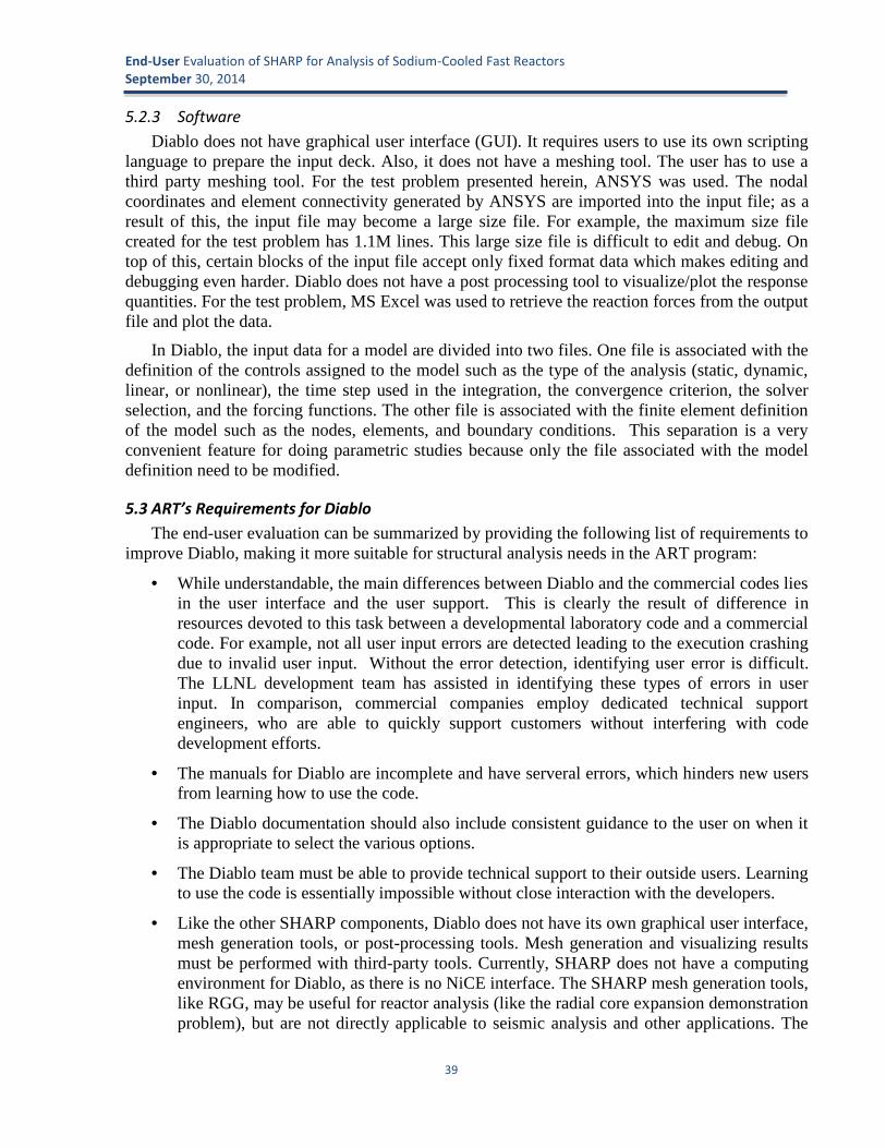
End-User Evaluation of SHARP for Analysis of Sodium-Cooled Fast ReactorsSeptember 30, 2014
39
5.2.3 SoftwareDiablo does not have graphical user interface (GUI). It requires users to use its own scripting
language to prepare the input deck. Also, it does not have a meshing tool. The user has to use athird party meshing tool. For the test problem presented herein, ANSYS was used. The nodalcoordinates and element connectivity generated by ANSYS are imported into the input file; as aresult of this, the input file may become a large size file. For example, the maximum size filecreated for the test problem has 1.1M lines. This large size file is difficult to edit and debug. Ontop of this, certain blocks of the input file accept only fixed format data which makes editing anddebugging even harder. Diablo does not have a post processing tool to visualize/plot the responsequantities. For the test problem, MS Excel was used to retrieve the reaction forces from the outputfile and plot the data.
In Diablo, the input data for a model are divided into two files. One file is associated with thedefinition of the controls assigned to the model such as the type of the analysis (static, dynamic,linear, or nonlinear), the time step used in the integration, the convergence criterion, the solverselection, and the forcing functions. The other file is associated with the finite element definitionof the model such as the nodes, elements, and boundary conditions. This separation is a veryconvenient feature for doing parametric studies because only the file associated with the modeldefinition need to be modified.
5.3 ART’s Requirements for DiabloThe end-user evaluation can be summarized by providing the following list of requirements to
improve Diablo, making it more suitable for structural analysis needs in the ART program:
While understandable, the main differences between Diablo and the commercial codes liesin the user interface and the user support. This is clearly the result of difference inresources devoted to this task between a developmental laboratory code and a commercialcode. For example, not all user input errors are detected leading to the execution crashingdue to invalid user input. Without the error detection, identifying user error is difficult.The LLNL development team has assisted in identifying these types of errors in userinput. In comparison, commercial companies employ dedicated technical supportengineers, who are able to quickly support customers without interfering with codedevelopment efforts.
The manuals for Diablo are incomplete and have serveral errors, which hinders new usersfrom learning how to use the code.
The Diablo documentation should also include consistent guidance to the user on when itis appropriate to select the various options.
The Diablo team must be able to provide technical support to their outside users. Learningto use the code is essentially impossible without close interaction with the developers.
Like the other SHARP components, Diablo does not have its own graphical user interface,mesh generation tools, or post-processing tools. Mesh generation and visualizing resultsmust be performed with third-party tools. Currently, SHARP does not have a computingenvironment for Diablo, as there is no NiCE interface. The SHARP mesh generation tools,like RGG, may be useful for reactor analysis (like the radial core expansion demonstrationproblem), but are not directly applicable to seismic analysis and other applications. The

End-User Evaluation of SHARP for Analysis of Sodium-Cooled Fast ReactorsSeptember 30, 2014
40
absence of these productivity tools is one of the primary reasons that commercial tools(like ANSYS and ABAQUS) will continue to be used for routine design and analysisneeds in the foreseeable future.
Diablo has focused on non-linear structural problems with contact. For reasons related tothis, the elements available are limited mostly low-order hexahedral and quadrilateralelements. In particular, a tetrahedaral element does not exist requiring brick elements formeshing. Meshing complex geometries with tetrahedral or hexahedral elements can bedifficult. It is possible in the linear analysis to use degenerated elements which thenassume prism or tetrahedral shapes.
Irradiation-induced swelling and creep models are required in order to represent realisticstructural deformation in nuclear reactor cores. ART engineers have implemented suchmodels in the commercial code ANSYS by developing user-defined materials and usercode that provides customized creep and swelling.
Although commercial tools do not provide access to the source code, they do provideanalysts with the means to add new capabilities (like irradiation-induced swelling andcreep models) through user-developed code. If it is not possible for ART engineers tohave full access to the Diablo source code, something like a user-code capability shouldbe provided so that engineers can augment Diablo without burdening the Diablodevelopment team.
Currently, Diablo is only available on UNIX/LINUX platform. To attract more users,making Diablo available for PC platform should be considered because it is moreeconomic and convenient for users to develop and test a small scaled model on local PCsto gain confidence before embarking the full scaled model on cluster computers.
The ART end-users hope that the NEAMS program can support these efforts, so that Diablocan be used to support ongoing analysis needs, such as core restraint design, safety performance,and soil-structure interaction.

End-User Evaluation of SHARP for Analysis of Sodium-Cooled Fast ReactorsSeptember 30, 2014
41
6 Computing Environment for SHARP (NiCE)The NEAMS Integrated Computational Environment (NiCE) is an open-source, Eclipse-based
GUI designed to facilitate the use of modeling and simulation codes [14]. The goal of this utilityis to support the full simulation process, including input file creation, job launching, and resultanalysis. Currently NiCE has some structure in place for Nek5000, PROTEUS, and SHARP as awhole. The NiCE team is also developing a utility called the SHARP Executable Release(SHARPER), which provides support for the setup and installation of SHARP codes.
6.1 NiCE for Nek5000NiCE currently features a Nek5000 Model Builder, which generates the necessary input files,
and a Nek5000 Launcher, which initiates a Nek5000 simulation using the files created by theModel Builder. NiCE developers have also recently created a Mesh Editor, which allows users tocreate new meshes for use with Nek5000.
One of the primary motivations behind NiCE’s Nek5000 features is to provide support foruniversity students taking courses in fluid dynamics and heat transfer. These students may be newto both Nek5000 and Linux systems, and they are working in the relatively short timeframe of auniversity semester. Therefore, having a tool which allows them to focus on the physics of theproblem, without having to learn unnecessary details about code use, could be beneficial. Thistype of utility could also be useful in training sessions, where new users are again working withina very limited timeframe. The intended support for Nek5000 is a good idea, but NiCE stillrequires a great deal of development before it is fully functional and useful for Nek5000 users.The tool was not evaluated by ART end-users.
6.2 NiCE for PROTEUSThe current PROTEUS features within NiCE are the PROTEUS Model Builder and the
PROTEUS Launcher. These tools are intended to create, and then run, a PROTEUS simulation.
6.2.1 PROTEUS Model BuilderThe PROTEUS Model Builder is a builder for the PROTEUS driver file, the text file that
contains the solution options and points to the other input files. There is currently no support forthe mesh, assignment, and cross-section files. Unfortunately, there are also numerous issues withthis driver file builder. The dialog window does not offer the full set of PROTEUS inputvariables, NiCE initially populates the input boxes with inappropriate values (probably from anexample problem) that are not the default values and there is no distinction between required andoptional variables. Additionally, all of the input spaces are text boxes where the user must typethe input, rather than drop-down menus or radio buttons, so using NiCE is no easier than justediting the text file by hand. In fact, for simple text input files like the PROTEUS driver file, mostusers are more likely to modify an existing input file than to create a new one from scratch in aGUI, since this is generally faster to do.
The dialog window assumes that there will always be exactly three external boundary surfaces(called sidesets) for which the user needs to specify boundary conditions. In reality, the user couldneed to specify any number of sidesets, including zero, depending on the geometry of theproblem. One of the advantages of PROTEUS over competing deterministic neutronics tools is

End-User Evaluation of SHARP for Analysis of Sodium-Cooled Fast ReactorsSeptember 30, 2014
42
that it accepts general geometries, so the PROTEUS Model Builder should not impose additionalrestrictions.
Overall, it appears that the developers may have examined a single example case and assumedthat its content applies to all cases when creating the PROTEUS Model Builder. Furthermore,when the actual content is written to the text file by the Model Builder, it is not written verycleanly (example shown in Figure 6-1). There is no formatting, and many extraneous comments(probably copied from an example problem) are written to the text file. While it is true that it isnot necessary for users to interact with the text file to run PROTEUS from NiCE, users may wantto utilize the NiCE-created file in other simulations. It is very common to build a text input with aGUI, and then to manually make small changes to the file as needed. Therefore, NiCE developersshould write the input file cleanly, with the assumption that some users may want to look at it.
(a)
(b)
Figure 6-1 PROTEUS Input Structure: (a) Example (Human-Created) Input FileDistributed with PROTEUS, compared to (b) Example Input File Written by NiCE

End-User Evaluation of SHARP for Analysis of Sodium-Cooled Fast ReactorsSeptember 30, 2014
43
NiCE does not allow the user to specify the filename when a new input is created. All inputsare by default named proteus_neutronics_num.inp, where the value of num is based on NiCE’sinternal tracking of model numbers. Changing this approach is not a top priority, but ultimately,users should be able to choose their own filenames. From a user perspective, it is much easier tokeep track of different simulations when the inputs are given logical names.
There are many areas where new utilities could assist in using PROTEUS. For example,within PROTEUS, the mesh, assignment, and cross-section inputs are developed separately, butmust be consistent with one another. Any job building or launching utility should check thatevery region in the mesh has a material (and material properties) in the assignment file, and thateach of those materials has data in the cross-section file.
In instances where users create their PROTEUS mesh in RGG, NiCE could serve as aninformation bridge between the two codes. In particular, NiCE could utilize the materialinformation in the RGG inputs as a starting point for the PROTEUS assignment file. NiCE couldalso keep track of pin and assembly lattice information, so that pin-by-pin power distributioninformation can be easily determined for meshes in which repeated structures have the sameregion number.
NiCE could also help to integrate the usage of PROTEUS with the usage of the existing ARCanalysis tools, like DIF3D/REBUS. As described above, PROTEUS is intended to supplement,but not replace, these codes. These codes have very cumbersome input that can be very difficultfor new users to grasp quickly. They also have fixed-format text based input, which makes iteasier for users to make mistakes. It would be very useful to develop utilities which can convertPROTEUS input into DIF3D-compatible data, and utilities which can take a common set of inputinformation and translate it into the input format needed by each code. Other, more extreme ideasinclude a tool that could convert a PROTEUS problem with detailed heterogenous assemblies intoa DIF3D input with radially-homogenized assemblies. In general, users may often want toevaluate detailed power distribution information in PROTEUS, and then evaluate more globalparameters such as total burnup in DIF3D/REBUS. From a user perspective, it is very helpful tonot have to construct a model from scratch to evaluate the same design with a different code.
6.2.2 PROTEUS LauncherThe PROTEUS Launcher is a utility for running PROTEUS simulations from within NiCE. It
is currently only capable of launching jobs locally or on select ORNL machines. Because allPROTEUS executables used in this evaluation were located on remote ANL machines, it was notpossible to test this utility.
The PROTEUS Launcher dialog box allows the user to input two pieces of information, thepath to the input driver file and the path to the PROTEUS executable. There is no structure forlaunching simulations in parallel. However, given the intended uses of PROTEUS, it is unlikelythat users will be running serial jobs. Therefore, the Launcher will only be useful if it is capableof submitting parallel simulations. This may not be easily achievable. Many of the machineswhere PROTEUS may be run have unique queuing systems or job submission formats that makeit unlikely that a universal job launching utility would work for them.

End-User Evaluation of SHARP for Analysis of Sodium-Cooled Fast ReactorsSeptember 30, 2014
44
In general, creating a launcher for PROTEUS is probably unnecessary. PROTEUS itself isfairly simple to launch, and given the complexity of the code, it is unlikely that there will be codeusers who do not know how to use a Linux terminal.
6.3 NiCE for SHARPNiCE currently offers two utilities related to running SHARP: a SHARP Model Builder, for
generating SHARP input files, and a SHARP Launcher, for initiating the SHARP codes to run ona local or remote system. NiCE also includes an output analysis tool for SHARP neutronics calledthe Reactor Analyzer. In addition, developers are working to implement a NiCE wrapper forVisIt.
6.3.1 SHARP Model Builder and LauncherAt this time, the SHARP Model Builder dialog window is identical to the PROTEUS Model
Builder discussed above. It is just a builder for the simple driver text file used by PROTEUS.There is not actually structure in place for creating a SHARP multiphysics problem. The SHARPLauncher similarly appears to be an exact duplicate of the PROTEUS Launcher.
Overall, coupled SHARP simulations are the area where NiCE could perhaps eventually offerthe most benefit to the code users, since these simulations require a complex management andtransfer of information from different codes. There are many features that could be added toNiCE to help support SHARP simulations. For example, it would be helpful to have checks forconsistencies in some of the model parameters between PROTEUS, Nek5000, and Diablo (e.g.,confirm that the coolant material is the same in all models). An even better utility would be onethat allows a user to input common information, such as the material in a geometric region, andthen translates that information into the different formats needed by each of the SHARP codes.Ideally, this utility could also be integrated with other codes necessary for SHARP simulations(such as MC2-3, which is used for cross-section generation). Anything that reduces redundanciesin the model creation process will have benefit to the user.
Ultimately, it would be useful for NiCE to also be integrated with RGG, MOAB, and anyother utilities SHARP code users may employ in creating their input files. The integration ofMOAB could be useful, for example, if a PROTEUS user constructs a .h5m mesh with RGG, andthen wants to convert it first to an exodus mesh (via MOAB’s mbconvert), and then a PROTEUS-compatible .nemesh file. If MOAB were integrated into NiCE, the user could perform all of thesesteps from within the GUI.
NiCE developers should also keep in mind that the probable user base for each of the SHARPcodes is not the same, and therefore the needs of the users may not be the same. Nek5000 is anolder code that already has a large set of users, and it will probably continue to expand its userbase since CFD is utilized across multiple engineering disciplines. In addition, there has alreadybeen interest in developing tools that facilitate the use of Nek5000 in a classroom setting.Therefore, having NiCE to simplify the use of Nek5000 could be very beneficial. PROTEUS, onthe other hand, is very specifically intended for analysis of nuclear reactors. PROTEUS also hasvery high computing power demands, and intelligent use of the code requires a goodunderstanding of neutron transport solution methods. Therefore, PROTEUS may not have asmany eventual users as Nek5000, and these users may not have the same “beginner” needs.

End-User Evaluation of SHARP for Analysis of Sodium-Cooled Fast ReactorsSeptember 30, 2014
45
6.3.2 Reactor Analyzer and VisIt InterfaceNiCE also includes a tool for evaluation of neutronics simulation results called the Reactor
Analyzer. This tool supports analysis on a core, assembly, or pin basis, for both light waterreactors (LWRs) and sodium-cooled fast reactors (SFRs).
NiCE does not currently have code structure in place for getting the information needed bythe Reactor Analyzer from a PROTEUS simulation. The HDF5 file used by the Reactor Analyzeris not the same HDF5 file produced by PROTEUS. The NiCE HDF5 file requires several types ofsolution data integrated over axial segments in each fuel pin and fuel assembly, but PROTEUSdoes not currently provide such integrated data. In general, PROTEUS does not have the conceptof a “pin” or an “assembly”, so producing such integrated data would require a significant codedevelopment effort. The NiCE developers state in the documentation: “While we were verysuccessful in making the infrastructure to view data from SHARP, we have not yet finished thework required to automatically generate NiCE’s HDF5 file.” This statement is somewhatmisleading, since there is still significant effort required to calculate this integrated data andgenerate the NiCE HDF5 file.
While engineers very frequently require integral core characteristics to be derived from theirsimulations, an output analysis tool should not limit itself to providing views of integrated data.One of the biggest advantages of PROTEUS over other neutronics codes is its ability to modelunconventional geometries, and to provide very detailed solutions. Therefore, any output analysistool should also facilitate visualizing and extracting detailed local solution data from PROTEUSpredictions. In response to this, NiCE developers are also working on adding a VisIt plugin forNiCE. VisIt has the capability to efficiently visualize the detailed solution data, but is notparticularly user-friendly. However, this utility requires VisIt2.8, which is still in beta and has notbeen released, so it was not possible to do any testing of it. If this plugin will offer functionsbeyond those currently available in standalone VisIt, or if this new interface will be user-friendlythan the existing VisIt interface, its development could provide benefit to SHARP code users.Users may often prefer to use a tool like this, which first presents the full solution, and thenallows them to evaluate averaged results or summary parameters from this data, rather than a toolwhich is strictly focused on select region-averaged values. The more flexible the output analysistools are, the more users they can benefit. Furthermore, PROTEUS users are not limited toanalyzing standard LWR and SFR geometries. Therefore, it is useful to have output analysis toolsthat can accommodate any geometry.
However, the Reactor Analyzer tool could provide benefits to analyzing results fromconventional reactor physics codes, like DIF3D, which employ assembly homogenization and arequite restrictive in the types of core geometry that can be represented.
As discussed in Section 3, there are indeed some instances where users are interested inexamining region-averaged values or summary values. In reactor design analysis, it is sometimesuseful to have a few representative parameters which allow a core to be assessed quickly. Inparticular, there has already been user interest in developing a utility for the determination ofpower peaking factors from PROTEUS simulations. Because of the wide variety of reactordesigns PROTEUS users may be simulating, it would be very difficult to develop a universalutility for power-peaking factor calculations. However, a method could be implemented fordetermining pin-specific data for runs where the mesh is generated with RGG, using the pin,

End-User Evaluation of SHARP for Analysis of Sodium-Cooled Fast ReactorsSeptember 30, 2014
46
assembly, and core specifications in the RGG input files. If NiCE is well-integrated with RGG, itcould facilitate this.
It should also be noted that one of the primary purposes of PROTEUS is use in coupled multi-physics SHARP simulations. Therefore, an output analysis tool for SHARP should not be solelyfocused on PROTEUS neutronics results. A much better utility would be something that lets theuser evaluate the relationships between the neutronics, thermal-hydraulics, and structural results.It would also be very useful to be able to examine how these relationships evolve over multipletimesteps of a given simulation.
The NiCE developers state that the Reactor Analyzer-compatible file would automatically becreated during a SHARP run launched by NiCE. While this would be fine to do, any outputanalysis tools should also be able to extract the necessary data from output files from jobs thatwere not run from within NiCE. Users often want to evaluate data from runs on other machines,or from runs done by colleagues.
6.4 Documentation and Code Developer SupportDocumentation on NiCE is currently provided in the form of a wiki site [14]. This site gives
an overview of the current features available in NiCE, including instructions on installation andusage.
The wiki documentation is very helpful. However, there are ways in which it could beimproved. Overall, the discussions of the NiCE features should be modified to better clarifyexactly what each feature does. For example, on the page “Using SHARP with NiCE”, the terms“SHARP” and “PROTEUS” are used somewhat interchangeably. There is discussion of a SHARPLauncher, which “can launch SHARP jobs in NiCE”. The wiki page claims “for now the SHARPLauncher only works locally and with a remote machine at ORNL”, but it is very unclear whatthis utility is actually capable of launching. It does not appear that there is any structure in placewithin NiCE for running coupled SHARP simulations, so this SHARP Launcher is probably infact a launcher for PROTEUS (and is therefore identical to the PROTEUS Launcher). If this is thecase, the documentation should be modified to state that the SHARP Launcher currently onlylaunches PROTEUS jobs, rather than implying it launches SHARP jobs. Inconsistencies such asthis make it very difficult for users to develop a clear picture of exactly what NiCE’s currentcapabilities are.
The NiCE development team was helpful throughout the evaluation process. They were quickto respond to emails and questions, and provided clarification when needed. They have beenreceptive to hearing feedback, and have expressed an interest in addressing the concerns that havebeen outlined above.
6.5 SHARPERThe SHARP codes have numerous third-party software dependencies, each of which must be
installed in a particular way for SHARP installation to be successful. To help handle thecomplexity of the SHARP installation process, a new utility SHARPER is being developed.SHARPER [39] is currently a collection of Bash scripts which manage the filesystem, andconfigure and install the necessary codes. According to the README file distributed with theSHARPER source code, SHARPER currently supports the SHARP codes Nek5000, MOAB, andPROTEUS, as well as the supporting software packages MPICH, HDF5, NetCDF, METIS,

End-User Evaluation of SHARP for Analysis of Sodium-Cooled Fast ReactorsSeptember 30, 2014
47
PETSc, and MOAB. The optional packages ParMETIS, VTK, and NiCE are also supported.SHARPER could be very beneficial to SHARP code users. In general, many analysts may nothave a great deal of experience in code development and installation. SHARPER will allow themto install codes that they otherwise may not have been able to install on their own. Even analystswith some experience in code installation could benefit from SHARPER because of thecomplexities involved in installing these interdependent codes.
In the future, it would be very helpful for SHARPER to be expanded to also includeinstallation of the SHARP mesh-generation toolkit MeshKit (and all additional supportingsoftware). This would require the introduction of several additional options to the installationscript, install.sh, because there is variety in the supporting codes users will want to install,depending on their planned usage of MeshKit.
This capability has not been sufficiently evaluated by the ART end-users.
6.6 ART’s Requirements for NiCEFurther development of NiCE should be approached with a more clear vision of the intended
final product, and all of its utilities and features. Currently, a great deal of work has been done onNiCE, but NiCE still does not provide benefit to SHARP code users because of “holes” in thedeveloped features. Before moving forward with NiCE development, there should be an overallplan regarding the features that need to be present in the final end product, as well as the pathnecessary to achieve those features. NiCE developers should focus on first creating the featuresthat could provide the most benefit to SHARP code users.
NiCE’s current support for SHARP (and the accompanying documentation) also gives theimpression that the NiCE developers have a somewhat limited understanding of the SHARPcodes. While it’s not necessary that they be experts, some degree of comprehension is essential toefficiently develop supporting utilities that are useful. Efforts should be made to better understandthe SHARP codes, with a focus on the aspects of these codes that make them unique from manyother codes available for nuclear reactor analysis. Other general recommendations for the NiCEdevelopers include:
Communicate more with the developers of the other SHARP codes regarding theutilities needed.
Be as specific as possible in the NiCE documentation when describing the individualNiCE utilities.
Keep in mind that the users of the individual SHARP physics codes may not have thesame experience level or needs, and therefore the support needed for these codes maynot be the same.
Develop the NiCE utilities based off of the SHARP code manuals, rather than exampleproblems, and keep in mind that there is a great deal of flexibility and variety in theinformation users may need to provide in the input files.
Ensure that any output analysis tools are not dependent upon the simulation being runfrom within NiCE.
Overall, having a supporting utility such as NiCE could be very helpful in SHARP codeusage. In general, users benefit from tools that allow them to easily build inputs, tools that can

End-User Evaluation of SHARP for Analysis of Sodium-Cooled Fast ReactorsSeptember 30, 2014
48
reduce redundancies in the analysis process (such as creating several different input models forthe same core design), and tools which help them easily transfer information from one code toanother. Specific capabilities which could be developed in NiCE in support of the SHARP codesinclude:
Integration of RGG so that RGG information (material assignments, pin layout withina lattice, etc.) are communicated to PROTEUS, and the other SHARP physics codes.
Integration of other supporting utilities such as MOAB’s mbconvert.
Support for SHARP coupled simulations by performing input consistency checks,developing utilities to reduce the redundant input that must be provided to each of thephysics codes, and developing output analysis tools which allow the user to evaluatethe relationships between the results of the neutronics, thermal-hydraulic, andstructural simulations (including the way these results change with time during atransient).
Support for evaluating the same design with both PROTEUS and the conventionalreactor physics code DIF3D/REBUS.
Integration of MC2-3, which is used for generation of cross-sections for PROTEUSand DIF3D.
Development of a result analysis toolkit which allows for evaluation of the high-resolution solution information, rather than just the specific data considered in thecurrent Reactor Analyzer.
Development of utilities to translate solution data from the format output by theSHARP codes to the format needed by NiCE. These utilities should be capable ofgetting the necessary information from the code output files, so that the outputanalysis tools are not limited to jobs that were run from within NiCE.

End-User Evaluation of SHARP for Analysis of Sodium-Cooled Fast ReactorsSeptember 30, 2014
49
7 Mesh Generation Tools (RGG)The Reactor Geometry Generator (RGG) is an open source toolkit for creating nuclear reactor
assembly and core geometries and meshes. RGG is one tool within the mesh generation libraryMeshKit [40]. MeshKit in turn is one of several interfaces and tools developed under SIGMA(Scalable Interfaces for Geometry and Mesh-based Applications) at ANL [41]. RGG consists oftwo tools: AssyGen, a utility for creating individual assembly mesh files, and CoreGen, a utilityfor compiling the component assemblies into a full reactor core mesh [42]. RGG utilizes CUBIT,a software toolkit for generation of two- and three-dimensional finite element meshes [20]. AGUI for RGG is also currently under development by the company Kitware, and an initial versionof the GUI was released recently [43].
Overall, it is very helpful for SHARP to offer tools for mesh generation. Users greatlyappreciate utilities that allow them to generate inputs more quickly. In addition, many newSHARP users may not have any previous experience with mesh generation. RGG, which is muchsimpler to learn than complex finite element meshing toolkits such as CUBIT, allows theseinexperienced users to begin performing simulations more quickly. It would be useful for SHARPdevelopment to continue to include the development of meshing tools, with a focus on specificfunctionalities that could benefit users of the different SHARP multi-physics codes.
Throughout the evaluation process, both the RGG documentation and the RGG code itselfunderwent frequent updates and revisions. Every effort has been made to assess the latestversions, but it is possible that some features have changed since they were evaluated for thisdiscussion.
7.1 RGG and MeshKit
7.1.1 Documentation and Code Developer SupportRGG suffers from a lack of documentation (on both code installation and usage), which
makes it difficult for analysts to use this toolkit. RGG has numerous code dependencies on third-party software, and these other codes must be installed prior to installation of RGG (which isinstalled within MeshKit). When the evaluation process began, the RGG installation instructionsprovided by the RGG developers were very out of date, and they did not clarify key informationsuch as incompatibilities among versions of the supporting codes. Many days were thereforewasted trying to install MeshKit and the supporting software, without success.
Additional documentation on RGG and MeshKit has been recently developed, but installationis still very poorly described. For example, the SIGMA website’s instructions for installingMeshKit and its dependencies includes installation of several codes (Triangle, Zoltan, Tetgen,etc.) that are not listed as dependencies in the README file distributed with RGG. There is noclarification of why the user may need these codes. This page also makes no mention of CUBITor installing CGM with a CUBIT dependency. Therefore, it does not appear that these areinstructions for installing MeshKit for RGG use. This is never stated however, and furthermorethe website does not appear to provide separate instructions for installing MeshKit for RGG.There are alternate installation instructions provided in the RGG README file, but these appearto be out of date. In general, the documentation on MeshKit installation should explicitly state theinstallation process, including the specific version number of each supporting code, and shouldclarify how the process differs for different MeshKit purposes. It would also be helpful if the

End-User Evaluation of SHARP for Analysis of Sodium-Cooled Fast ReactorsSeptember 30, 2014
50
documentation mentions issues frequently encountered in the installation process, and how toresolve them. Beyond the development of improved documentation, it would be even morehelpful if a utility was developed to perform the installation process (including the installation ofall dependencies) for users.
It would also be useful for the MeshKit documentation to briefly explain what the codedependencies are, and why the user may need them. Of course, each of these codes has its owndocumentation. However, when there are ten or more dependencies, some of which are notalways necessary, it is not reasonable to expect a new MeshKit user to pursue findingdocumentation on each of these codes, or to expect them to know which codes are needed in aparticular case. The MeshKit documentation should provide summary information on these codes,in the context of their application within MeshKit. This will help users make more informeddecisions regarding whether they need each of these codes for their analysis purposes.
Overall, the MeshKit documentation appears to assume that users are already fairly familiarwith other meshing tools (including all of the code dependencies). Many terms are also usedwithout explanation. For example, on the RGG webpage, the AssyGen is description states “TheAssyGen tool is the first step of the three-step core mesh creation process, it reads an input filedescribing a reactor assembly lattice and generates an ACIS or OCC -based geometry file”.However, there is no additional discussion of what ACIS and OCC mean, or what the differencesare between these geometry file types. From a user perspective, it would be very helpful to havebrief discussions of background information like this within the code manual, so that the userdoesn’t have to search for external references. Some SHARP users may not have any previousexperience with mesh generation, and they will find additional clarification very helpful.
The RGG documentation also does not provide enough information on code usage. There is abrief definition of each input variable, but little information on how these variables are actuallyapplied. In some instances, there is not even sufficient information on how to specify the variablein the input file. For example, for the variable NeumannSet, the RGG documentation states “Itcan take values ‘top’, ‘bot’, or ‘side’ ”. However, to use the keyword “side”, the user must alsoinput the equation for the line that forms the particular side (by providing the a, b, c, and d valuesof the line equation ax+by+cz=d). This is not indicated anywhere in the RGG documentation, butwas learned through emails with the RGG developers.
As with PROTEUS, it also would be helpful if the RGG documentation gave some basicinformation on CUBIT. In particular, the documentation should briefly discuss the CUBIT files(filename.jou, filename.template.jou, and filename.sat) created by AssyGen.
It would also be useful to have more documentation connecting RGG with the SHARPphysics codes. For example, to create a mesh for PROTEUS, the individual assemblies must becreated with the flag “CreateSideSet no”. However, the only information in the RGG manual onthis variable is “Option to disable sideset creation for CUBIT journal file. Takes values ‘yes’ or‘no’”. This provides users with no information on the purpose of this variable, and it is neverstated that this variable must be set to “no” for a PROTEUS mesh. In general, if RGG is meant tobe a utility within the SHARP package, there should be documentation (either in the RGG manualor the individual SHARP physics code manuals) on how to correctly use RGG for each of thecodes. Many analysts who are new to using RGG will be new to using the other SHARP codes aswell, and they would greatly benefit from this type of information.

End-User Evaluation of SHARP for Analysis of Sodium-Cooled Fast ReactorsSeptember 30, 2014
51
The RGG developers were helpful during the evaluation process. They were willing to meetwhenever necessary, both to provide an introduction to the code and later to resolve issues. Theyresponded quickly to emails, and provided clarification when asked. However, they did not do agood job of providing detailed installation instructions, which delayed the evaluation process.They also did not install RGG (and the necessary supporting software) on any machines withinANL’s Nuclear Engineering Division. Unfortunately, this meant that the only usable version ofRGG was an installation in one of the code developer’s directories on the MCS machines. Thiscaused significant problems because the code developers were constantly modifying thisinstallation. RGG is of course still under development, and it is understandable that the codedevelopers are primarily focused on continuing to improve their toolkit. However, it would begood for the project managers to encourage more of a dedicated effort towards user support, inaddition to code development. This would go very far in developing a larger user base for RGG.
7.1.2 Usability and Ability to Meet User NeedsOverall, RGG provides a great deal of benefit to users who are evaluating standard LWR and
SFR geometries. For example, in the EBR-II analysis discussed in Section 3.1, it would havetaken much longer to develop the mesh files without RGG, and the process would have requiredmore familiarity with CUBIT. The well-defined structure of the RGG input files also made it easyto develop a script for creating the PROTEUS assignment file.
As mentioned in the discussion of NiCE, the analysis process could be further enhanced bythe development of tools that can utilize the information in the RGG inputs for the SHARPphysics codes. Examples include using the material information in the RGG input files as astarting point for developing the PROTEUS assignment file, and tracking the pin and assemblylayout information for use in evaluating power peaking factors in meshes where repeatedgeometries all have the same region number.
There are both advantages and disadvantages to RGG’s use of CUBIT. CUBIT is a robust,stable toolkit. It allows code users to view both individual assembly and full-core models in aflexible, three-dimensional view that is much more sophisticated than tools like VisEd for MCNPor the VisIt mesh viewing capabilities available with DIF3D. However, one drawback to CUBITis that it may be difficult for some RGG users to obtain this software. According to the CUBITwebsite, there is no charge for U.S. government-use licenses of CUBIT, but academic andcommercial users of the code must obtain licenses from the private company ComputationalSimulation Software LLC (csimsoft).
One of the biggest issues with the RGG code itself is a lack of detailed error messages. Thereare many simple error checks that code developers could implement that would be very helpfulfor users. For example, if coregen cannot find one of the assembly models, it currently prints“Couldn’t read mesh file. Failed to load meshes.” This gives no indication of which assemblymesh file it could not load. It also does not clarify whether there was a problem with the file or itcouldn’t find the file. In general, it would be good to establish a series of checks for RGG toperform before it constructs a full core model, and to indicate in any error messages exactlywhich assembly file failed the checks. RGG developers could also work with the developers ofthe SHARP physics codes to establish other error or warning messages for mesh features thatwould be an issue in simulations. Error messages provide tremendous benefit to code usersbecause they can prevent users from having to spend hours (or even days) trying to pinpoint whysomething went wrong.

End-User Evaluation of SHARP for Analysis of Sodium-Cooled Fast ReactorsSeptember 30, 2014
52
As another example, coregen sometimes prints “Warning: acis file has sequence numbers!”.This message may print multiple times, implying that it is being issued for multiple assemblyfiles. However, there is no way to determine which of the assembly files it refers to. Furthermore,this message is not discussed at all in the RGG documentation, making it impossible for the RGGuser to tell if this is actually a problem. Similarly, whenever CUBIT is run with one of the RGG-generated journal files to create an assembly model, it will terminate with “ERROR: Errors foundduring the CUBIT session” whenever the assembly model has sidesets. RGG developers haveconfirmed via email that this is a known issue that can be ignored, but this is not mentionedanywhere in the RGG documentation, which could easily lead users to waste a great deal of timetrying to determine whether there is a problem.
It also seems like the code developers may not have good in-team checks in place foridentifying errors as they modify the code. As mentioned above, the EBR-II analysis was limitedbecause the RGG utilities used to build the model were constantly being changed by thedevelopers, which occasionally introduced issues. It would be good for the RGG developers toestablish a set of verification models that they rebuild and examine each time changes are made tothe code. These checks should confirm that regions and sidesets are correctly labeled, that themesh has the intended degree of refinement, and so on.
7.2 RGG GUIThe initial release of the RGG GUI occurred very recently, and only limited testing has been
performed with the GUI. The intended features of the GUI include creating AssyGen andCoregen inputs from scratch, running AssyGen and CoreGen, loading existing AssyGen andCoreGen input files, and visualizing the final RGG-created mesh file.
Overall, the GUI could enhance the RGG user’s experience. Currently, the user can onlyvisualize an RGG-created full-core model by first running RGG and then converting the .h5mmesh to an exodus file, which can then be viewed in CUBIT. The new RGG GUI now allowsusers to visualize the same core model without having to first run RGG. This is a much faster wayto confirm the core model will be built as anticipated.
One significant issue is that there is not good consistency between the documentationprovided by the RGG GUI developers, and the SIGMA team, the developers of RGG andMeshKit. Most importantly, the two are not consistent in their definition of RGG. The GUIdocumentation states that RGG “is an open-source graphical user interface (GUI) tool” and thatAssyGen and CoreGen are tools utilized by RGG. The SIGMA team’s website, on the other hand,states that AssyGen and CoreGen are utilities within RGG, and that the GUI is a supporting utilityfor RGG. This inconsistency is present throughout the documentation. For example, both theKitware documentation and the SIGMA team website provide information that they each refer toas “RGG installation instructions”. However, Kitware’s instructions are for installing the GUI,while the SIGMA team’s instructions are for installing the MeshKit package. Overall, this is aminor detail, but referring to two separate entities (a code and the GUI that supports the code)both by the name “RGG” could easily lead to confusion. There should be a consistent definitionof “RGG”.
The GUI development team was helpful during the evaluation process. They respondedquickly to emails, and were very persistent in resolving a set of (never before seen) errormessages that occurred when the GUI was installed on an NE laptop.

End-User Evaluation of SHARP for Analysis of Sodium-Cooled Fast ReactorsSeptember 30, 2014
53
7.3 ART’s Requirements for RGGRGG offers a very useful method for easily creating models of standard SFR and LWR
geometries. However, the code’s usability is hampered by the lack of documentation oninstallation and usage, and by a lack of error checks in the code structure. The following providesa summary of the topics that should be added to RGG documentation:
Installation
o Brief overview of each of the code dependencies
o Clarification of when/why particular dependencies are needed
o Explicit instructions for installing MeshKit (including the differences ininstalling MeshKit for RGG vs. MeshKit for other purposes)
o Clarification of the required specific versions of each of the supporting codes
o Explanation of terms used in the current documentation that are not commonlyknown, such as the difference between ACIS and OCC
Usage
o More detailed explanation of the input variables and how they are used byRGG
o Instructions on using RGG to create meshes for the individual SHARP physicscodes
o Explanation of RGG error messages
o Discussion of CUBIT in the context of RGG
In addition to improved documentation, the following items should also be pursued:
Improved verification checks within the RGG development team to ensure that errorsare not introduced with code changes
Improved error checks in the AssyGen and CoreGen code structures, for both
o Issues that will cause a problem at some point in the mesh creation process
o Issues that will not prevent mesh creation, but will be a problem if the mesh isused with a SHARP physics code
Increased detail in current error messages (e.g., if the error occurs with one of severalassembly files being used in a core model, the error message should clarify whichassembly file)
Development of utilities which communicate RGG information (material assignments,pin layout within a lattice, etc.) to PROTEUS, or the other SHARP physics codes asneeded

End-User Evaluation of SHARP for Analysis of Sodium-Cooled Fast ReactorsSeptember 30, 2014
54
8 Summary of ART’s Requirements for SHARPART engineers have been given the opportunity to use the SHARP advanced modeling and
simulation tool kit for nuclear reactors, and have provided a detailed evaluation of their utility forthe analysis needs of the program. This section provides a summary of those items deemed mostimportant.
The strengths of SHARP are the accuracy of its physics models, the capability to modelarbitrary geometries, emphasis on validation, and scalability on high performance computers. TheNEAMS organization has taken the right approach by selecting and further developing codes withadvanced physics models; without such improved models there would be little incentive forengineers to invest in learning new tools. While most of the engineers performing this evaluationare accustomed to performing simulations on desktop workstations, SHARP’s performance onparallel machines will certainly be advantageous in the future as computing power growsexponentially. NEAMS has also invested in validation of their models, primarily by analyzingexperiments that focus on a single phenomenon, and provided results to the community. Furtherprogress in each of these are certainly possible, but the overall philosophy seems to be correct.
Although the ART engineers agree that the primary code development effort must be built ona foundation of accurate models and efficient algorithms, the tools will not be adopted byengineers unless there is a relatively straightforward process to build models and extractmeaningful results. The ART end-users encountered several challenges while trying to learn howto use the codes, and often found the workflow tedious. The end-users would like to make thefollowing recommendations regarding code use:
Significant updates are required to the documentation of both the SHARP physics codesand the supporting elements. There is also a gap between the documentation of thesupporting tools (e.g. RGG, VisIt) required for model development and post-processing,and the physics codes themselves, where neither set of manuals provide user guidance oncode-specific issues. More importantly, there is no documentation to describe theprocedure for performing multi-physics simulations with SHARP, which would beessential for its adoption.
The complex installation process for SHARP and supporting elements, especially MOABand RGG, are providing a substantive hindrance to new users interested in using SHARP.The recent version of MOAB and RGG has yet to be installed on workstations inArgonne’s Nuclear Engineering Division.
The SHARP suite of tools provides highly resolved information about the reactor, butanalysts are frequently interested in larger scale core characteristics—such as powerpeaking factors, average channel or assembly outlet temperature, maximum claddingtemperature in each fuel pin. The required information is available from the SHARPsolution, but the analyst would need to integrate the solution data. One possible solutionwould be to develop a utility that works with RGG to recognize common units like pinsand assemblies, so that data can be integrated over pins and assemblies later. Moreadvanced tools for integrating over arbitrary regions would be beneficial for otherapplications.
Both Nek5000 and Diablo impose strict requirements for the types of mesh that can beused. Although such meshes may produce more accurate results, they are usually time-

End-User Evaluation of SHARP for Analysis of Sodium-Cooled Fast ReactorsSeptember 30, 2014
55
consuming for most analysts to generate for complex geometries. The NEAMS teamshould respond with a plan for reducing this barrier to entry for Nek5000, e.g. by allowingmore flexible meshing, or by furthering the development of MeshKit and RGG, or perhapsby working with commercial vendors for mesh generation to recommend tools to newusers.
Each of the SHARP physics modules need additional error checks to insure consistentuser input. This will facilitate the process for model development, and ensure that analystsare using the codes properly.
The SHARP team must be able to provide technical support to their outside users.Learning to use the code is essentially impossible without close interaction with thedevelopers.
The ART program is making significant investments to understand and quantify phenomenarelated to structural core deformation in SFRs. If advanced modeling and simulation tools canprovide a higher degree of confidence in the prediction of the reactor’s response to thesestructural deformations, we have the potential to reduce capital costs for new SFR concepts, whilemaintaining safety performance. Furthermore, we may have a stronger position when advocatingfor the inclusion of radial core expansion feedback—and corresponding changes to core restraintdesign—with our international partners. By performing integrated neutronics, thermal-hydraulics,and structural mechanics simulation on relevant length- and time-scales to explicitly treat theimportant phenomena, the SHARP tools are demonstrating the potential to fulfill this modelingneed. In particular, PROTEUS is unique in its capability to perform large-scale deterministicmulti-group neutron transport simulations on arbitrary reactor geometries—including SFRs withdeformed fuel subassemblies. Before SHARP can be relied upon for design and licensing needs,IT will need to be thoroughly validated against experimental data, such as the FFTF datacurrently being recovered by ART. Additional modeling capabilities and code features would alsobe required. The list of requirements for the particular problem of radial core expansion includes:
For safety analysis, quasi-static simulations are insufficient. A time-dependent capabilityrequires a significant development effort in PROTEUS, which includes only an adiabatickinetics feature, and improved quasi-static is likely necessary.
The calculation procedure for performing multi-physics SHARP simulations, especiallywith the structural mechanics code Diablo, must be automated so that they can beperformed in a practical manner.
Because the fuel, cladding, and coolant are homogenized inside the ducts of the fuelassembly, isotope densities within the homogenized region must be adjusted to conservemass as the deformations cause volume changes. Currently, these adjustments do notaccount for thermal expansion of the fuel, which should be considered in future work.
PROTEUS lacks the capability to predict photon transport, and a gamma heating modelwould be necessary for accurate simulations. Photon transport would be useful for otherapplications, too, including as estimating the flux at a detector location.
The spatial mesh for all three physics modules was relatively coarse, as the objective wasfor demonstration rather than validation. Further work should be performed to providesimulations for a spatially-converged mesh, which would also provide insight into the

End-User Evaluation of SHARP for Analysis of Sodium-Cooled Fast ReactorsSeptember 30, 2014
56
computational expense of running these simulations and test the RGG mesh generationtool. Similar studies are required to ensure that the multigroup cross section library issufficient.
The effort’s scope was expanded to include an evaluation of PROTEUS, Nek5000, andDiablo as single physics codes for other applications. Additional recommendations for thephysics modules include:
Each of the SHARP physics codes (PROTEUS, Nek5000, and Diablo) require furthervalidation before they can be relied upon for nuclear reactor analysis. In particular, thePROTEUS code requires significant verification and validation to ensure its predictionsare reliable for a range of reactor physics problems. In addition, multi-physics SHARPsimulations require verification (i.e. to ensure the correct data is being transmittedbetween code modules) and validation (i.e. to ensure that integral reactor behavior ispredicted correctly).
Coupling PROTEUS to a depletion code would enable analysts to predict how the detailedflux profile affects burnup, and would provide depleted compositions to PROTEUSwithout a multi-stage simulation.
The computational expense of Large Eddy Simulations is often significantly greater thanthe RANS techniques offered by commercial tools like STAR-CCM+. The continueddevelopment of the unsteady RANS capability in Nek5000 would enhance its appeal toART’s needs.
Irradiation-induced swelling and creep models for Diablo would be required to accuratelyrepresent structural deformation in nuclear reactor cores.
The ART engineers were able to access the full source code for PROTEUS and Nek5000,but were prohibited from accessing the Diablo source code. The commercial structuralmechanics codes that ART engineers use do not provide access to their proprietary sourcecode, either. However, they do provide analysts with limited means to add newcapabilities (like irradiation-induced swelling and creep models) through user-developedcode. If it is not possible for ART engineers to have full access to the Diablo source code,something like a user-code capability should be provided so that engineers can makeminor augmentations without burdening the Diablo developers.
The ART end-users hope that this feedback will be constructive, and help guide the NEAMSprogram towards development efforts that will be useful to engineers performing SFR analysis.This report should mark the beginning of a collaborative effort, not just the end of an exercise.

End-User Evaluation of SHARP for Analysis of Sodium-Cooled Fast ReactorsSeptember 30, 2014
57
9 References1. A. Siegel, T. Tautges, A. Caceres, D. Kaushik, P. Fischer, G. Palmiotti, M.A. Smith, J.
Ragusa, “Software Design of SHARP,” in Proceedings of the Joint International TopicalMeeting on Mathematics and Computations and Supercomputing in Nuclear Applications(M&C + SNA), American Nuclear Society, April 2007.
2. D. Parsons, J.M. Solberg, R.M. Ferencz, M.A. Havstad, N.E. Hodge, and A.P. Wemhoff,“Diablo User Manual”, Lawrence Livermore National Laboratory report UCRL-SM-234927,Sept. 2007.
3. E.R. Shemon, M.A. Smith, C. Lee, A. Marin-Lafleche, “PROTEUS-SN User Manual:Revision 1.1”, ANL/NE-14/6, August 2014.
4. E.R. Shemon, M.A. Smith, C. Lee, “PROTEUS-SN Methodology Manual”, ANL/NE-14/5,June 2014. .
5. P.F. Fischer, J.W. Lottes, S.G. Kerkemier, Nek5000 Web Page, http://Nek5000.mcs.anl.gov,2008.
6. T.J. Tautges, R. Meyers, K. Merkley, C. Stimpson, C. Ernst, “MOAB: A Mesh-OrientedDatabase”, Sandia National Laboratories report SAND2004-1592, April 2004.
7. R. Jain, T.J. Tautges, “RGG: Reactor Geometry (and Mesh) Generator”, presented atInternational Congress on the Advances in Nuclear Power Plants, Chicago, 2012.
8. E.R. Shemon, C. Lee, “PROTEUS Training Summary”, ANL-ARC-286, April 2014.
9. A. Obabko, “NEAMS Nek5000 Training”, ANL-ARC-287, August 2014.
10. Y.I. Chang, P.J. Finck, C. Grandy, Advanced Burner Test Reactor Preconceptual DesignReport” Argonne National Laboratory report ANL-ABR-1 (ANL-AFCI-173), Sept. 2006.
11. E.R. Shemon, J.J. Grudzinski, C.H. Lee, J.W. Thomas, “Specification of the AdvancedBurner Test Reactor Coupling Demonstration Problem: ARC Multi-Physics CouplingDemonstration”, ANL-ARC-284, January 2014.
12. E. Merzari, E.R. Shemon, J.W. Thomas, A. Obabko, R. Jain, V. Mahadevan, T. Tautges, J.Solberg, R. Ferencz, R. Whitesides, “Multi-Physics Demonstration Problem with the SHARPReactor Simulation Toolkit”, ANL-ARC-283, January 2014.
13. E. Merzari, E.R. Shemon, Y. Yu, J.W. Thomas, A. Obabko, R. Jain, V. Mahadevan, J.Solberg, R. Ferencz, R. Whitesides, “Full Core Multi-Physics Simulation with Offline MeshDeformation”, April 2014.
14. J.J. Billings, et al, “NiCE User Manual”, https://sourceforge.net/projects/niceproject/, 2014.
15. H. Childs et al, “VisIt: An End-User Tool for Visualizing and Analyzing Very Large Data”,High-Performance Visualization – Enabling Extreme-Scale Scientific Insight, p. 357-372,Oct. 2012.
16. J.J. Billings, J. Deyton, A. Wojtowicz, “Demonstration of NiCE User EnvironmentCustomized for ARC Users (revised)”, April 2014.

End-User Evaluation of SHARP for Analysis of Sodium-Cooled Fast ReactorsSeptember 30, 2014
58
17. J. J. Grudzinski, C. Grandy, “Fuel Assembly Bowing and Core Restraint Design in FastReactors”, Proceedings of ASME 2014 International Mechanical & Engineering Congress &Exposition (IMECE 2014), Montreal, Canada, November 2014.
18. T. H. Fanning, ed., “The SAS4A/SASSYS-1 Safety Analysis Code System”, ANL/NE-12/4,Nuclear Engineering Division, Argonne National Laboratory, January 31, 2012.
19. T. Fei, A. Mohamed, T.K. Kim, “Neutronics Benchmark Specifications for EBR-II ShutdownHeat Removal Test SHRT-45R-Revision 1”, ANL-ARC-228, January 2013.
20. Sandia National Laboratory, CUBIT Website, https://cubit.sandia.gov/ , 2010.
21. C.H. Lee and W. S. Yang, “MC2-3: Multigroup Cross Section Generation Code for FastReactor Analysis”, ANL/NE-11-41, September 2011
22. T.P. Gerrity III, “MCODE-3: Time-Dependent Depletion Isotopics with MCNP-5 andSCALE-6.1”, Massachusetts Institute of Technology, 2012.
23. X-5 Monte Carlo Team, Los Alamos National Laboratory, “MCNP – A General Monte CarloN-Particle Transport Code, Version 5; Volume II: User’s Guide”, LA-CP-03-0245, February2008. .
24. W.D. Pointer, et al, “Simulations of Turbulent Diffusion in Wire-Wrapped Sodium FastReactor Fuel Assemblies”, 2009 International Conference on Fast Reactors and Related FuelCycles (FR09), Kyoto, Japan, December 7-11, 2009.
25. E. Merzari, W. D. Pointer, J.G. Smith, A. Tentner, P. Fischer, “Numerical Simulation of theFlow in Wire-Wrapped Pin Bundles: Effect of Pin-Wire Contact Modeling”, NuclearEngineering and Design, 253, p. 374-386, 2012.
26. Y. Yu, S. Aithal, A. Obabko, J. Walker, J.W. Thomas, “CFD Validation with the SodiumTriple-Jet Mixing Experiment PLAJEST: STC-A7 CEA/JAEA/DOE Collaboration on SFRThermal-Hydraulics”, ANL-ARC-289, July 2014.
27. K.M.Becker, C.H.Ling, S.Hedberg, G.Strand, “An Experimental Investigation of Post DryoutHeat Transfer,” Department of Nuclear Reactor Engineering, Royal Institute of Technology,KTH-NEL-33, Sweden, 1983.
28. CD-adapco, Ltd., “STAR-CCM+ User’s Manual”, 2014.29. F.E. Dunn, Cahalan, J.E., “Whole Core Sub-Channel Analysis Verification with the EBR-II
SHRT-17 Test”, ICAPP’06, Reno, NV USA, June 4-8, 2006.
30. T.H Fanning, et al, “Multi-Resolution Modeling of Subassembly Pin Bundles for AdvancedFast Reactor Safety Simulations”, M&C 2009, Saratoga Springs, New York, May 3-7, 2009
31. E. Merzari, et al, “Hydrodynamic Analysis of Different Spacing Strategies for a Tight-LatticeSFR Bundle”, Transactions of the American Nuclear Society, 103, November 2011.
32. A. V. Obabko, A. E. Aksenova, V. V. Chudanov, P. F. Fischer, V.M. Goloviznin, A.A.Kanaev, S. Karabasov, E. Merzari, S. Parker, V. A. Pervichko, W. D. Pointer, T. Taugets, M.A. Zaytsev, "Cross-verification and validation simulations of Matis benchmark," ANL/TM-341, 2014 (in preparation)

End-User Evaluation of SHARP for Analysis of Sodium-Cooled Fast ReactorsSeptember 30, 2014
59
33. S. M. Aithal, P. F. Fischer, O. Marin, E. Merzari, A. V. Obabko, Y. Yu, and W. D. Pointer,"LES and RANS simulations of the ANL MAX experiment for various inlet boundaryconditions," ANL/MCS-TM-337, September 30, 2013.
34. S. Lomperski, E. Merzari, and D. Pointer, P. Fischer and A. Obabko, "MAX Startup Tests,"ANL-NE 10/28, September 2010.
35. Lysmer, J., and Kuhlemeyer, R. L., “Finite Dynamic Model for Infinite Media,” Journal of theEngineering Mechanics Division, ASCE, pp. 859-977, August, 1969.
36. ASCE 4-98, “Seismic Analysis of Safety-Related Nuclear Structures and Commentary”,ASCE Standard, American Society of Civil Engineers.
37. Tang, Y and Solberg, J., 2014, private communication.
38. Wong, H.L., and Luco, J.E., “Tables of Impedance Functions and Input Motions forRectangular Foundations”, Report No. CE 78-15, University of Southern California, LosAngeles, CA, 1978.
39. A. R. Bennett and J. Billings, SHARPER wiki, http://sourceforge.net/p/sharper/wiki/Home/ .
40. SIGMA Development Team, MeshKit Website, http://sigma.mcs.anl.gov/meshkit-library/,2014.
41. SIGMA Development Team, SIGMA Website, http://sigma.mcs.anl.gov/ , 2014.
42. SIGMA Development Team, RGG Website, http://press3.mcs.anl.gov/sigma/meshkit-library/rgg/ , 2014.
43. Kitware, Inc.,CMB RGG Website, http://www.computationalmodelbuilder.org/rgg/ , 2014.


Argonne National Laboratory is a U.S. Department of Energylaboratory managed by UChicago Argonne, LLC
Nuclear Engineering DivisionArgonne National Laboratory9700 South Cass Avenue, Bldg. 208Argonne, IL 60439
www.anl.gov