endotracheal tube to reduce the incidence of ventilator
TRANSCRIPT
Endotracheal tube to reduce the incidence of
ventilator associated pneumonia
Final Report
May 5, 2010
Evan Joyce (Co-Team Leader)
Scott Carpenter (Co-Team Leader)
Ryan Childs (BSAC)
Paul Fossum (BWIG)
Ozair Chaudhry (Communicator)
Client: Mark Schroeder, M.D.
Advisor: Professor Amit Nimunkar, PhD.
BME 301 – University of Wisconsin-Madison 1
Table of Contents
Abstract …………………………………………………………...…..……………..……...3
Introduction ………………………………………………………..…………………..……......4
Mechanical ventilation
VAP – What is it?
VAP – What causes it?
VAP – Why fix it?
Current ETT problems & overall goal
Existing Technology …………………………………..………………………...………..…….10
Standard tubes
VAP – reducing technology
Client Specifications ………………………………..………………………………..…………11
Overall design goals
Design parameters
Additional client requirements and/or desires
Preliminary Prototypes …......……………….…………..…………………………….…...…..12
Current coil
Insertion tool
Cuff wrapper
Sterile sleeve
Testing ………………….……………………………………………..…………….……18
Cuff wrapper
Sterile sleeve
Cost Analysis ……………………………………………………………………………………21
Future Work ………………….……………………………………………..…………….……22
Current coil testing
Fabrication and patenting
Conclusion …………………...……………………………………………...………………..25
References ………………..…………………………………………………………………..26
Appendix ……………….……………………………………………………..…………….28
BME 301 – University of Wisconsin-Madison 2
Product design specifications (PDS)
Fluid leakage testing protocol
Spectrophotometer testing protocol
BME 301 – University of Wisconsin-Madison 3
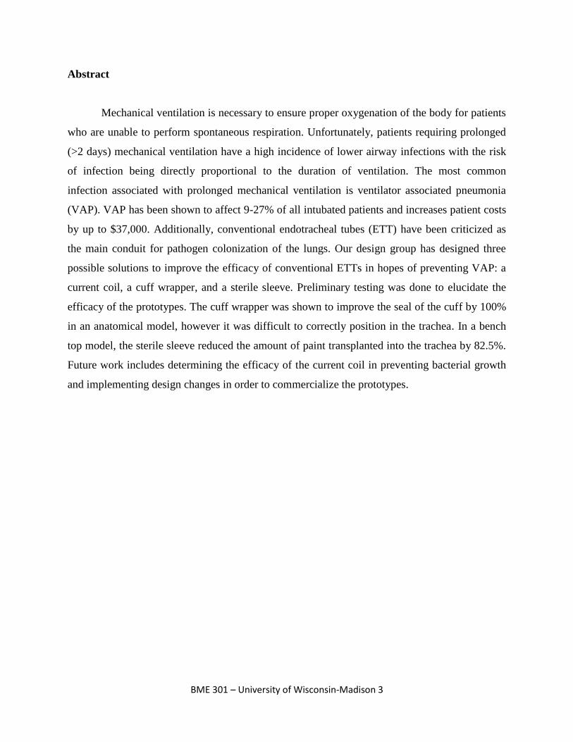
Abstract
Mechanical ventilation is necessary to ensure proper oxygenation of the body for patients
who are unable to perform spontaneous respiration. Unfortunately, patients requiring prolonged
(>2 days) mechanical ventilation have a high incidence of lower airway infections with the risk
of infection being directly proportional to the duration of ventilation. The most common
infection associated with prolonged mechanical ventilation is ventilator associated pneumonia
(VAP). VAP has been shown to affect 9-27% of all intubated patients and increases patient costs
by up to $37,000. Additionally, conventional endotracheal tubes (ETT) have been criticized as
the main conduit for pathogen colonization of the lungs. Our design group has designed three
possible solutions to improve the efficacy of conventional ETTs in hopes of preventing VAP: a
current coil, a cuff wrapper, and a sterile sleeve. Preliminary testing was done to elucidate the
efficacy of the prototypes. The cuff wrapper was shown to improve the seal of the cuff by 100%
in an anatomical model, however it was difficult to correctly position in the trachea. In a bench
top model, the sterile sleeve reduced the amount of paint transplanted into the trachea by 82.5%.
Future work includes determining the efficacy of the current coil in preventing bacterial growth
and implementing design changes in order to commercialize the prototypes.
BME 301 – University of Wisconsin-Madison 4
Introduction
Mechanical ventilation
Mechanical ventilation, the use of a mechanical respirator to inflate and deflate the lungs,
is used when a patient is unable to maintain adequate oxygenation of the body on their own. A
mechanical ventilator uses positive pressure breathing (increased pressure of the air source) to
force air into the alveoli of the lungs where it can then be exchanged with the rest of the
body.[11] A patient’s inability to adequately oxygenate the body can occur for a variety of
reasons with the most common being when they are under the influence of general anesthesia or
as a result of serious illness or injury.[3] Mechanical ventilation can be used as either a short
term solution (as in during an operation) or a long term solution (such as an home treatment of a
chronic illness). Mechanical ventilation is accomplished through either the use of non-invasive
or invasive techniques. Non-invasive mechanical ventilation normally consists of a physician or
nurse compressing and releasing an air filled bag in order to force air into the lungs. This type of
ventilation is normally used as an intermediate short-term solution to a ventilation problem or in
circumstances where a ventilator machine is not present. Invasive mechanical ventilation is the
primary type of ventilation used during surgery and consists of a ventilator machine designed to
forcefully move air into and out of the lungs through an endotracheal tube (ETT), tracheostomy
tube, or tracheal tube.[7]
While mechanical ventilation is at times a necessary life preserving process it is
associated with several health risks that are a cause for concern. One of the most common health
concerns with mechanical ventilation is the development of ventilator associated pneumonia
(VAP). VAP is a common occurrence in elderly and young patients along with many in the ICU
because of their compromised ability to fight off infections. Studies have shown that VAP risk
increases with the duration of mechanical ventilation and is directly linked to the presence of
either an endotracheal or tracheostomy tube in the patient’s airway. The presence of the tube is
believed to increase the risk of obtaining VAP as it both impairs the natural mucocilliary
clearance process and disrupts the cough reflex. This inhibition consequently allows bacteria to
more easily enter the lungs.[5]
BME 301 – University of Wisconsin-Madison 5
VAP – What is it?
Ventilator associated pneumonia (VAP) is the most common and dangerous nosocomial
infection in hospitals among all patients.[2,8,10,13,14,19] VAP is an infection defined as
pneumonia occurring in an intubated patient 48 hours or more after mechanical ventilation and is
observed in 9-27% of all intubated patients. It is further classified as either early onset (<96
hours after start of mechanical ventilation) or late onset (>96 hours after start of mechanical
ventilation) with both variations posing an equal risk to the patient’s health and safety.[13]
Certain risk factors increase the likelihood of acquiring VAP including age, structural lung
disease, prior tracheobonchial colonization, pneumonia severity, and reason for admittance to the
ICU or ER (burns and multiple trauma injury), but no patients are completely risk free.[2,14]
While mechanical ventilation through an ETT is necessary in life-saving situations, its presence
within the trachea is known to produce injury in the trachea mucosa, introduce endogenous and
exogenous bacteria, impede the cough reflex, prevent muscocilliary clearance, and provide a
direct conduit for microaspirations of bacteria into the lungs.[2,13,14] Due to the differences in
symptoms and patient response to VAP, diagnosis is often difficult and adds to the complications
surrounding this deadly infection.
A prompt diagnosis of VAP and identification of the pathogen or pathogens responsible
for its onset is crucial for proper treatment. Most diagnostic tests available are constantly
evolving to ensure both quick and accurate conclusions, but most include a narrowly defined list
of clinical observations and criteria. The Clinical Pulmonary Infection Score (CPIS) is one such
method defined by six criterion including: a chest x-ray examination, body temperature reading,
white blood cell count, tracheobronchial secretion analysis, pulmonary function impairment, and
an absence of alternative sources of infection.[19] These criteria are evaluated collectively to
define an episode of pneumonia. Another scored test used to predict VAP severity and mortality
is the VAP PIRO system (Predisposition, Insult, Response, Organ dysfunction) which depends
on four variables independently associated with mortality (presence of comorbidities,
bacteremia, shock, and acute respiratory distress syndrome).[2] Scored systems may be used to
predict the severity of a case of pneumonia or VAP, but it is also necessary to determine the
bacteria or virus responsible to ensure proper treatment. Bacterial or viral classification is
accomplished by either Gram staining or bacteria-specific agar culture testing.[2,10,14,19]
BME 301 – University of Wisconsin-Madison 6
Aspiration of either bacterial or viral pathogens into the lungs is the primary mechanism
by which a mechanically ventilated patient acquires VAP. The most common microorganisms
responsible for VAP are Staphylococcus aureus, Haemophilus influenza, Psuedomonas
aeruginoa, Klebsiella sp., and Escherichia coli.[2,13,19] While these opportunistic bacteria may
be either naturally present within the trachea or introduced exogenously (intubation process,
gastrointestinal back-flow, esphogeal secretions, or oropharyngeal secretions), a lack of an
immune response allows for rapid colonization of the lungs.[2,19] The well known ability for
bacteria to adhere to biomedical polymers leads to an increase in the incidence of bacterial
aspiration into the lungs.[8,10] Gram staining is often used for diagnosis of bacterial presence in
the lungs and this also helps in determining a proper antibiotic treatment.
Treatment of VAP is largely limited to single antibiotic treatments, antibiotic cocktail
treatments, or the immediate removal from ETT intubation and transfer to either tracheostomy or
non-invasive mechanical ventilation.[2,13,14] Antibiotic routes of treatment include topical
administration, intravenous delivery, and aerosolized sprays with most antibiotics falling into
either broad-spectrum or targeted-therapy agent categories. With the ever-growing concern of
antibiotic resistant microorganisms, current treatment recommendations favor the use of a single
antibiotic agent for each pathogen present (targeted-therapy agents).[2] While general trends
indicate most patients respond well to antibiotic treatments, a failure to respond to initial
treatment is considered a serious event associated with excess adverse outcomes.[2,19] Both
non-invasive and tracheostomy airways restore some host defense mechanisms and allow for
easier cleaning of bacteria laden secretions in the throat and trachea; both methods have been
shown to reduce the incidence of VAP.[13]
VAP – What causes it?
The presence of an ETT in the trachea prohibits the cough reflex and reduces
muscocilliary clearance which indirectly leads to the collection of subglottic secretions in the
trachea both above and below the inflatable ETT cuff.[13] Since the body lacks a mechanism to
clear the excessive accumulation of thick, mucus-like secretions, if left for an extended period of
time, it is inevitably aspirated into the lungs. Once aspirated into the lungs, rapid bacterial
colonization may develop and result in VAP.[2,13,14] Normal day-to-day physiological
processes allow a person to prevent aspiration of fluids. For example, if fluid enters the lungs it
BME 301 – University of Wisconsin-Madison 7
will irritate sensitive cilia hairs that line the trachea below the vocal cords or the sensitive carina
which is located where the two main bronchi branch, leading to a cough reflex to expel the
insulting material. In addition to the cough reflex, resident tissue macrophages (alveolar
macrophages), neutrophils, and phagocytotic immune cells in the lung tissue rapidly destroy any
remaining bacteria.[1] Under homeostatic conditions bacteria present in the body do not pose a
threat to one’s health, but when the body is stressed benign and foreign bacteria may become
opportunistic and hazardous.
Gastrointestinal tract back-flow, oropharyngeal/esphogeal secretions, and oral bacteria
are the three main sources of pathogenic bacteria able to invade the trachea during prolonged
mechanical ventilation.[2,14,19] The order of bacterial colonization in the body and an in situ
ETT is the oropharynx, stomach, lower respiratory tract, and finally the ETT.[13] Usually, by the
time bacteria have colonized the outside and inside lumens of the ETT, an intubated patient will
already have, or be at high risk for developing, VAP. During mechanical ventilation normal
digestion and stomach functions are often impaired and allow for a bacterial back-flow from both
the normally highly acidic stomach and the bacteria rich gastrointestinal tract.[13,14] During
periods of critical illness and high stress (such as an ER or ICU visit), the oral flora is
dramatically altered with a marked increase in aerobic Gram-negative bacilli and Staphylococcus
aureus. These bacteria are able to migrate through saliva and other bodily secretions to the
subglottic sections pooled within the trachea or are directly inoculated into the trachea mucosa
during the intubation process.[13] Pooled subglottic secretions in the trachea provide the perfect
medium for bacteria growth and proliferation.
Mucus-like secretions and saliva pooled in the trachea along the ETT and above the
inflatable cuff is a highly effective route of bacterial entry into the lungs. Aspiration of these
pooled secretions past the inflatable cuff has been well documented as a primary cause of VAP
during prolonged mechanical ventilation.[13,14] Thick secretions are difficult to remove through
conventional means (thin suction tubing) and are continually secreted by tissues in the
oropharynx and trachea as a means of lubrication. Secretions that bypass the ETT are often
inhaled and exhaled through the inner lumen of the ETT during positive pressure ventilation and
exhalation and thus allow for the final stage of bacterial colonization: biofilm formation.[13]
A biofilm can be defined as the mechanical attachment of a bacterial community to an
inert, non-living object and is used as a means of protection and community communication.
BME 301 – University of Wisconsin-Madison 8
Bacterial communities are able to lie in a dormant, hypometabolic sessile state surrounded by a
protective polymeric extracellular matrix that provides protection from both the immune
response and antibiotic treatments.[13,14] While the presence of a biofilm on in vivo biomedical
devices has been correlated to prolonged infection it remains unclear as to whether or not biofilm
formation poses a significant risk for acquiring VAP, but it is noted that ETT biofilm formation
has been observed in numerous VAP case studies ranging from 70 – 100% of cases.[13,14] One
possible route of entry is the partial or full detachment of a biofilm from the inner lumen of an
ETT from the shear forces from the influx of ventilator inspiratory gases.[13] Preventing a
biofilm from forming or its removal from the outside and inside lumens of an ETT may reduce
the occurrence of VAP in mechanically ventilated patients.
VAP - Why fix it?
VAP and its potential causes are an active area of clinical research due to its frequency
and severity. VAP is one of the most common hospital acquired infections, and the most
common and deadly infection in the ICU. Nationally, there are nearly a quarter million cases
annually resulting in over 35,000 deaths. Over 90% of all hospital acquired pneumonias occur in
patients who have undergone mechanical ventilation.[6] Historically VAP occurs in 9-27% of all
intubated patients.[4] On average, an incidence of VAP increases the length of ICU stay by 28%
and is estimated to increase the cost of patient treatment by $10,000 to $37,000.[18] VAP is such
an expensive and frequent problem that if an endotracheal tube could be developed to stop VAP
it has been calculated that hospitals could spend upwards of $388 per tube for every surgery
conducted and still save money when compared to the annual cost associated with VAP.[15]
Conventional ETT problems & overall goal
Since numerous studies have pointed to the ETT as the major pathogenesis in the
development of VAP, it is only natural to assume there are potential improvements that could be
implemented to reduce the risk factors associated with ETT induced VAP. As noted earlier the
key risk factors associated with ETT induced VAP are: the implantation of exogenous and
endogenous bacteria in the tracheal mucosa during intubation, inhibition of natural mucocilliary
and cough reflexes from clearing subglottic secretions, pooling and aspiration of subglottic
secretions, and biofilm formation on the ETT’s interior and exterior surfaces. Current
BME 301 – University of Wisconsin-Madison 9
endotracheal tubes leave room for improvement because they fall short in addressing these issues
in the following ways:
They allow subglottic secretions collected above the inflated ETT cuff to leak to the
distal end of the ETT via longitudinal folds that form in the inflated cuff membrane.
These secretions are subsequently aspirated into the lungs
Because of the unwillingness to use selective decontamination, due to the fear of resistant
strains of bacteria, current tubes have no way of completely decontaminating the
subglottic space
There has yet to be a cost effective method to prevent/remove biofilms from an ETTs
exterior surface
No method has been developed to prevent the transfer and deposition of endogenous
bacteria from the mouth and upper throat into the tracheal mucosa during intubation
Current ETT designs have no completely effective way to maintain a decontaminated
environment in the inner lumen
No way has been developed to mimic the mucocilliary clearance and cough reflex
ETT’s are unable to effectively minimize the pressure on the vocal cords and trachea
endothelial cells
These noted short comings have paved the way for the development of a system (used in
conjunction with ETTs currently on the market or a completely new ETT design) that addresses
the major risk factors of VAP by improving the performance of the cuff, maintaining a more
sterile environment in the inner and outer ETT surfaces, and minimizing the potential for
contamination of the tracheal mucosa by the ETT during intubation. These potential areas of
improvement, along with the danger and cost associated with VAP, are the driving force behind
this project which looks to address the inadequacies of current ETT designs in order to create a
tube that prevents VAP.
BME 301 – University of Wisconsin-Madison 10
Existing Technology
Standard tubes
Endotracheal tubes have been used to supply oxygen to the lung alveoli during surgery
for decades. Currently there are several different ETT types and sizes used during surgery. The
most common types used are oral or nasal polyvinyl chloride (PVC) cuffed tubes (the cuff is
used to seal the airway). The inner diameter of PVC oral tubes ranges from 2 to 10.5 mm. An
un-cuffed oral tube may be used during surgery on a child because their trachea diameter is small
enough that the presence of an ETT is enough to create an effective seal. In addition to the most
commonly used ETT, anesthesiologists may choose to use a variety of specialty ETTs depending
on surgical circumstances. Specialty tubes include RAE tubes (preformed to a specific curvature
to reduce trachea pressure and improve insertion), reinforced tubes (for laser surgery), and
double lumen tubes (used for single lung ventilation or intrathoracic surgery to collapse a lung).
VAP-reducing technology
In response to the growing concern about VAP and its close association with
endotracheal tubes, several different ETTs have been developed in an attempt to reduce the
incidence of VAP. The most effective and commonly used of these is the silver coated or
impregnated tube. Silver acts as a natural antibacterial agent helping to eliminate biofilm
formation and has been shown to significantly lower the rate of aerobic bacteria colonization on
both the inner and outer lumen.[6] In addition to silver coated tubes, tubes have looked to use
suction or friction to remove subglotic secretions on both the tubes inner and outer lumens.
Specifically the Hi-Lo Evac tube and the Mucus Slurper look to use continuous subglotic
secretion removal, from above and below the cuff respectively, while the Mucus Shaver uses
periodic surface friction to remove biofilms or mucus on the inner ETT lumen. Furthermore,
companies like Kimberly Clark, have replaced high volume low pressure (HVLP) PVC cuffs
with lower density polyurethane and low volume high pressure (LVHP) silicone cuffs in hopes
of eliminating the longitudinal folds that act as conduits allowing bacteria laden pharyngeal
secretions to leak into the lungs. Finally, there are several patents that begin to introduce the use
of various gels, anti-microbial elements, suction, electricity, and multiple cuffs in hopes of
preventing bacteria from entering the lungs.
BME 301 – University of Wisconsin-Madison 11
USPTO application # 20090101152 (high surface area anti-microbial coated ETT)
USP 5725510 (use of Ag salt, foil, or vapor deposited coatings on ETT’s)
USP 7452345 (use of antimicrobial coating, electrical current, or ultrasound)
USPC 604150 (lavage put into trachea to suction out degradative gel)
Despite recent developments, there is currently no ETT on the market, or system that can
be used in conjunction with existing tubes, with a design that combines a variety of both passive
and active systems, capable of eliminating or minimizing the primary risks of ETT induced VAP.
Client Specifications
Overall design goals
Improve the design of current ETTs in order to reduce the significant risk factors
associated with VAP. To be accomplished by addressing some or all of the three improvement
areas listed below:
Improve the ETT’s cuff to minimize or eliminate the leakage of subglottic pharyngeal
secretions into the lungs
Minimize or eliminate the risk of tracheal mucosa exogenous bacterial contamination
from the ETT as it passes through the mouth and pharynx during intubation
Create and maintain a sterile environment above the ETT cuff
Reduce or eliminate the formation of bacterial biofilms on the interior and exterior
surfaces of the ETT
Design parameters
The previously mentioned design requirements deal with specific areas on the ETT that
need to be improved. The remaining design parameters refer to a general semester outline and
the project deliverables for the initial (prototype) phase:
Concept development – develop a variety of concept designs aimed at addressing the
three main improvement areas noted above
Select the most promising and feasible design concepts for further development and
prototyping
BME 301 – University of Wisconsin-Madison 12
Build preliminary prototype(s) for under $1000
Do testing of prototype(s) and obtain preliminary data which demonstrates: system
functionality, improved ETT performance, and patient safety
Additional client requirements and/or desires
Prototype(s) can be either an add system designed to be used in conjunction with ETTs
that are currently widely used in hospitals (most desirable) or an entirely new ETT design
that incorporates the newly developed features
If any aspect of the system is intended to reusable, prototype(s) must be compatible with
hospital sterilization practices (MetriCide cleaning solution)
Prototype must be safe for the patient and compatible with trachea endothelia cells
If possible reduce the pressure on the vocal cords associated with intubation and the
ETTs presence in the trachea
Preliminary Prototypes
Current coil
The current coil consists of silver-plated stainless steel wires in a double helix shape
connected to a resistor and a battery. Numerous studies have shown that silver is a powerful anti-
microbial agent and thus the incorporation of silver plated wires are in an attempt to kill VAP
causing bacteria.[9,17] By sending a current through the wires silver ions are ejected from the
wire and these ions act as anti-bacterial agents. With the current coil’s design, there is only a
complete circuit when mucus accumulates between each rung of the coil and thus it will only
exert an anti-microbial effect when VAP causing bacteria are present.
The stainless steel compression coils were purchased from WB Jones Spring Company
and were made of 302-stainless steel (product # 715). The coil was then platted by Professional
Plating Inc. with a Silver Plate of 0.00015 inch minimum thickness per MIL-QQ-S-365D, over a
Silver-Strike Flash plate of 0.00001 inch minimum thickness per MIL-QQ-S-365D. This ensures
a uniform silver coating around the entire circumference of the stainless steel wires. Nickel-
Sulfamate was also plated as a base coat to ensure that the silver would adhere to the steel wires.
Next, the steel coils were cut to a length of 11.43 cm to ensure a proper fit in the distal
BME 301 – University of Wisconsin-Madison 13
one-third of the ETT. The silver-plated coil diameter was 7.94 mm which was chosen to ensure
the current coil friction fit inside the ETT while the wire diameter of 0.67 mm was chosen so that
the coil would remain rigid after insertion. The coil pitch was set at 2.89 mm to ensure an
overlap of the coils. The anode is the area where the bacteria are destroyed by the silver ion
particles so the pitch was selected at a distance of less than 5 mm to allow for anode overlap.
This provides an anti-microbial effect to the entire coil.[16]
The construction of the double helix wires involved using two separate pieces of silver-
plated wires and epoxy. Each coil piece was intertwined by hand around a ¼ in x 4 in hex-head
bolt while maintaining a constant separation of 1.445 mm (half of the coil pitch) between any
two rungs of the coil. This unit was then glued together with Gorilla Epoxy and held to air dry to
ensure the pitch between successive wires did not change. Several units were made in a similar
way to provide an adequate amount for testing.
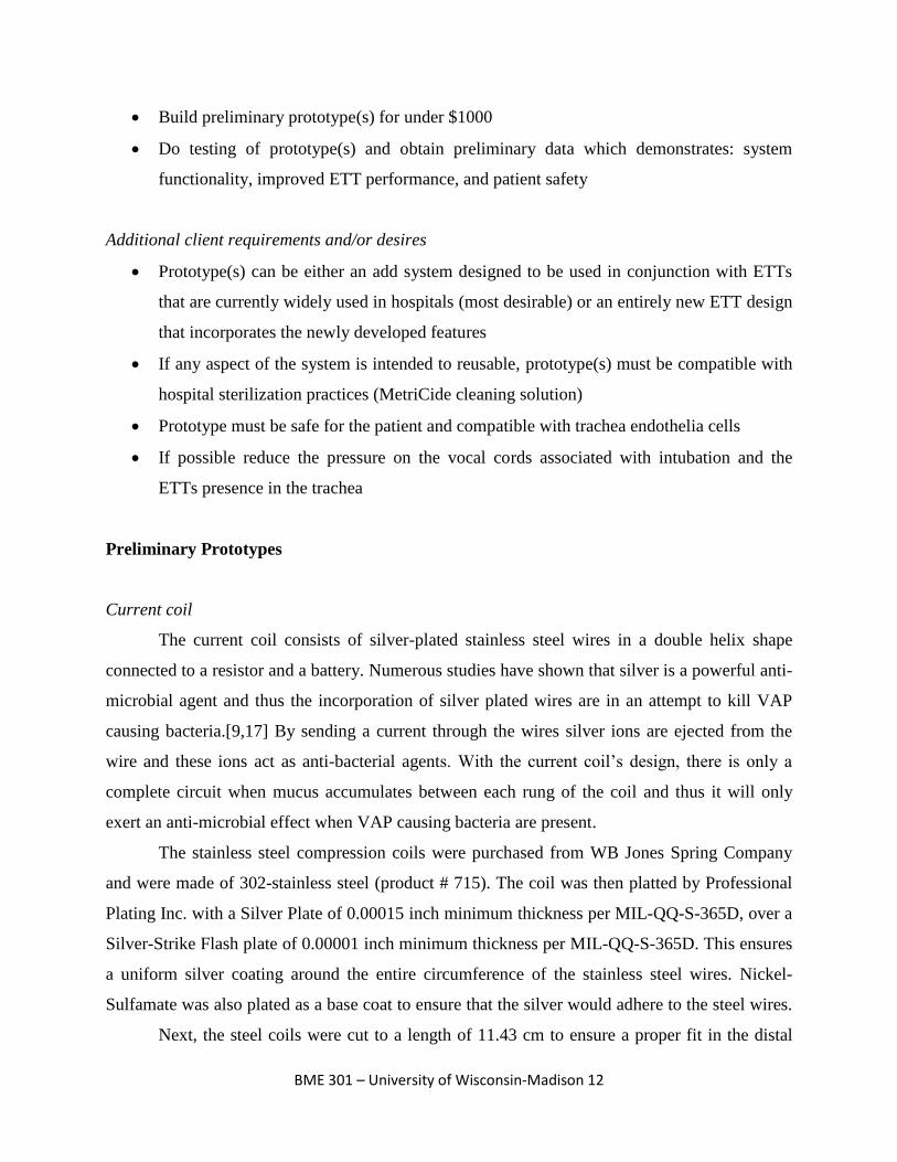
A 4.8 mm x 1.5 mm 3V Lithium battery (Digi-Key part number P003CT-ND) was used
to construct the current coil unit. A 271 kΩ resistor was placed in series with the battery to make
a constant current source. This configuration produces roughly 9-10 µA and was done to ensure
an adequate current at all times to generate enough silver ions to destroy bacteria based on a
literature review.[9,16,17] The circuit was attached onto the double helix unit with the help of
Peter Klomberg, who soldered it together. The current coil units can be seen in Figure 1 below.
Figure 1: Two different length current coils with resistor and battery attached
BME 301 – University of Wisconsin-Madison 14
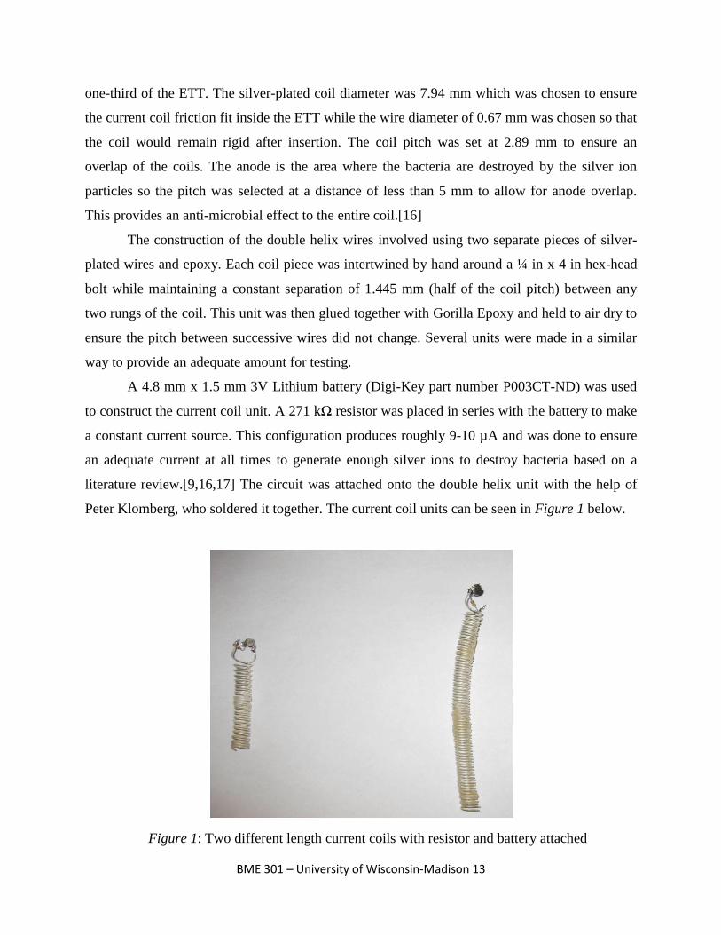
In order to increase the ease and feasibility of both creating and inserting the double helix
pieces, without the use of epoxy, a supplemental tool was designed.
Insertion tool
After the initial production of the test current coils it was determined that an insertion
tool was needed (see Figure 2 below) to not only allow for a more efficient production of the
current coils, but to also allow for an easy insertion into the end of the ETT. The main objective
of the insertion tool was to allow for the coils to be fabricated easily and inserted into the ETT
while maintaining a constant pitch between the two intertwined helical coils. Maintaining a
constant pitch between the coils is important for two reasons: 1) if the coils were to touch the
circuit would short and the coil would be rendered useless and 2) the pitch between successive
anodes must be kept below 5 mm to ensure a complete anti-microbial effect. The insertion tool
solves both of these problems in two main ways: by providing a constant pitch to the coils
through the use of screw-like grooves and by offering rigidity to the coil during insertion. The
off-set grooves provide a track for the two coils to screw into, which allows them to be uniformly
separated, by the acrylic insertion tool, along the coil’s entire length. By separating the coils with
a rigid plastic (acrylic), the tool not only prevents the coils from shorting out but also helps to
preserve the shelf life of the battery by preventing any current flow between the wires during
shipping and transport.
Figure 2: ProEngineering model of the insertion tool. Length of threads is 10.16 cm and
the tool is made out of acrylic
BME 301 – University of Wisconsin-Madison 15
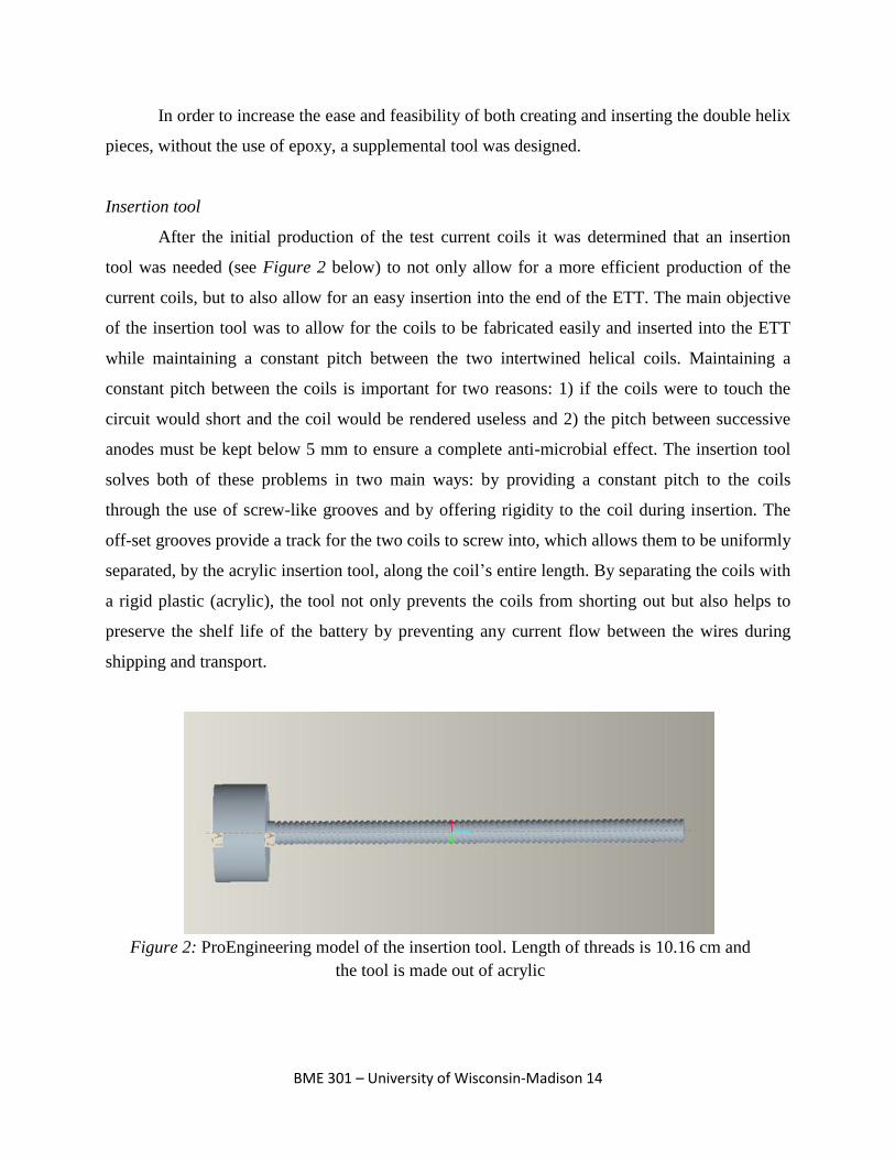
Since the ratio of the length:wire diameter of the coil is relatively large the insertion tool
was also needed to allow a physician to insert the coil into the distal end of the ETT. Without the
use of the insertion tool the coil would simply bend and compress upon insertion which would
force the coils together causing them to short out. Even if the bending and compressing did not
force the coils together it would make the insertion of the coil a time consuming process and
could cause the coil to lose other structural properties (i.e., flaking of the silver plating). By
allowing the coils to securely screw onto a solid core (see Figure 3 below) the tool prevents the
coils from compressing or bending and provides the physician with a handle from which they
can provide the required insertion torque.
The insertion tool was designed on ProEngineering after discussions with Professor Amit
Nimunkar and 3M engineer Mark Childs. The tool was manufactured by Doug Dummer at the
UW-Madison Physics Machine Shop. The original specifications of the tool had a groove depth
of ¾x the wire diameter, width of slightly larger than 1x wire diameter, and groove off-sets of
1.44 mm. After discussions with Doug Dummer it was determined that a pitch of 2.89 mm and
groove width of 0.864 mm was needed to allow for the removal of the tool after insertion of the
coil into the ETT. In addition to these changes the handle of the tool was elongated from 2.54 cm
to 11.5 cm in order to allow the user the ability to more easily provide the required insertion
force and removal torque. The grooves of the tool run 10.16 cm but eventually need to be
elongated to 11.43 cm to allow for complete coil stability. Finally, the insertion tool was made
from acrylic plastic because it is an easy plastic to machine and also provides the physical and
mechanical properties which were required.
Figure 3: Insertion tool with both coils wrapped around it. Notice the constant
pitch of the coils and the clear plastic between every rung
BME 301 – University of Wisconsin-Madison 16
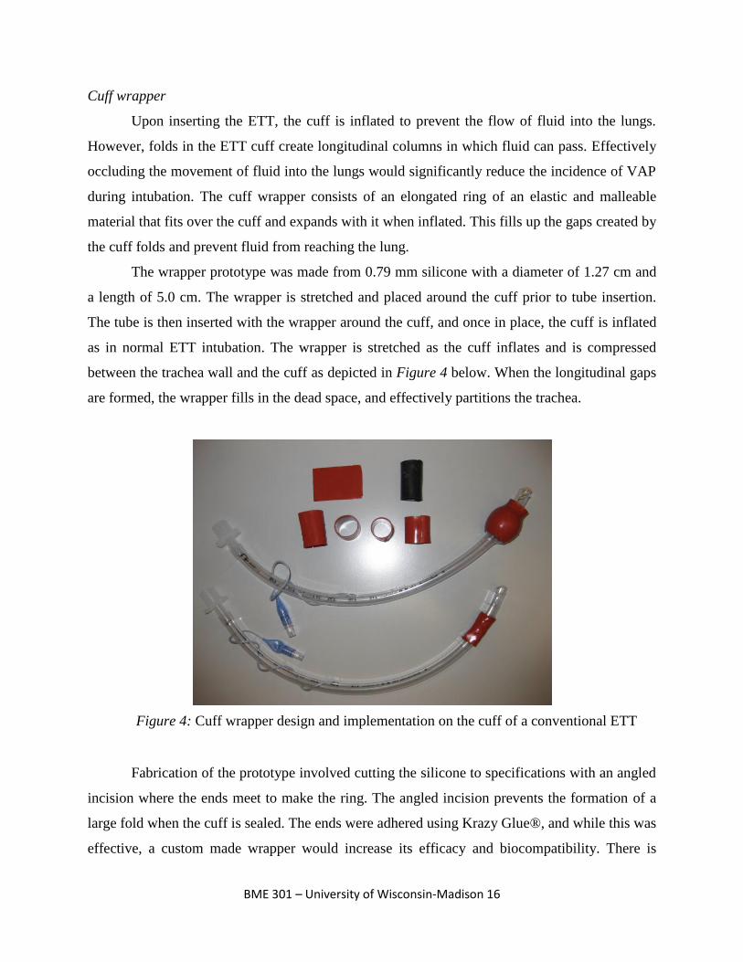
Cuff wrapper
Upon inserting the ETT, the cuff is inflated to prevent the flow of fluid into the lungs.
However, folds in the ETT cuff create longitudinal columns in which fluid can pass. Effectively
occluding the movement of fluid into the lungs would significantly reduce the incidence of VAP
during intubation. The cuff wrapper consists of an elongated ring of an elastic and malleable
material that fits over the cuff and expands with it when inflated. This fills up the gaps created by
the cuff folds and prevent fluid from reaching the lung.
The wrapper prototype was made from 0.79 mm silicone with a diameter of 1.27 cm and
a length of 5.0 cm. The wrapper is stretched and placed around the cuff prior to tube insertion.
The tube is then inserted with the wrapper around the cuff, and once in place, the cuff is inflated
as in normal ETT intubation. The wrapper is stretched as the cuff inflates and is compressed
between the trachea wall and the cuff as depicted in Figure 4 below. When the longitudinal gaps
are formed, the wrapper fills in the dead space, and effectively partitions the trachea.
Fabrication of the prototype involved cutting the silicone to specifications with an angled
incision where the ends meet to make the ring. The angled incision prevents the formation of a
large fold when the cuff is sealed. The ends were adhered using Krazy Glue®, and while this was
effective, a custom made wrapper would increase its efficacy and biocompatibility. There is
Figure 4: Cuff wrapper design and implementation on the cuff of a conventional ETT
BME 301 – University of Wisconsin-Madison 17
currently no method to securely fix the wrapper to the tube other than the elastic recoil inherent
to the material used and this design flaw is discussed in future work.
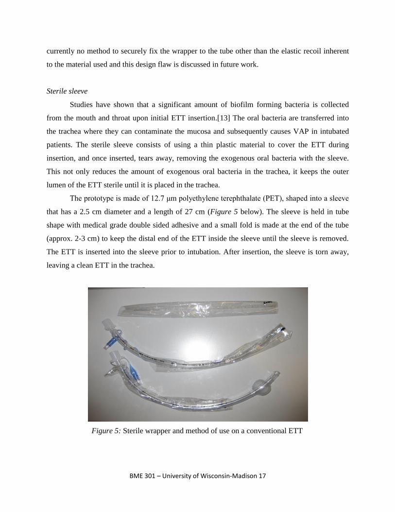
Sterile sleeve
Studies have shown that a significant amount of biofilm forming bacteria is collected
from the mouth and throat upon initial ETT insertion.[13] The oral bacteria are transferred into
the trachea where they can contaminate the mucosa and subsequently causes VAP in intubated
patients. The sterile sleeve consists of using a thin plastic material to cover the ETT during
insertion, and once inserted, tears away, removing the exogenous oral bacteria with the sleeve.
This not only reduces the amount of exogenous oral bacteria in the trachea, it keeps the outer
lumen of the ETT sterile until it is placed in the trachea.
The prototype is made of 12.7 μm polyethylene terephthalate (PET), shaped into a sleeve
that has a 2.5 cm diameter and a length of 27 cm (Figure 5 below). The sleeve is held in tube
shape with medical grade double sided adhesive and a small fold is made at the end of the tube
(approx. 2-3 cm) to keep the distal end of the ETT inside the sleeve until the sleeve is removed.
The ETT is inserted into the sleeve prior to intubation. After insertion, the sleeve is torn away,
leaving a clean ETT in the trachea.
Figure 5: Sterile wrapper and method of use on a conventional ETT
BME 301 – University of Wisconsin-Madison 18
To assist the operation of the prototype, the PET was cut to include a tab at the proximal
end to which the person inserting the ETT can grip. Also, a small cut was made close to the tab
to help the PET tear. There were some problems with the material used as the PET produced too
much friction with the PVC tube and could not be efficiently removed. This was fixed by placing
a strip of medical grade cellophane tape on the outside curve of the ETT, thereby reducing the
friction enough to easily tear away the sleeve.
Testing
Cuff wrapper
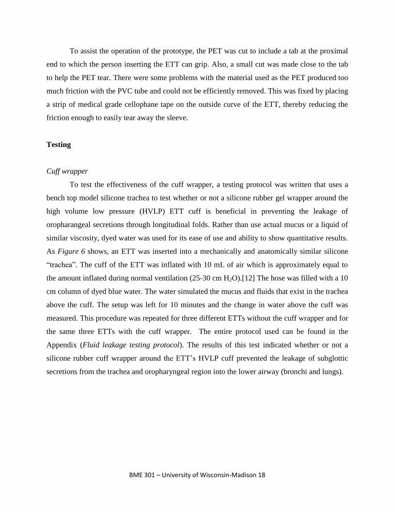
To test the effectiveness of the cuff wrapper, a testing protocol was written that uses a
bench top model silicone trachea to test whether or not a silicone rubber gel wrapper around the
high volume low pressure (HVLP) ETT cuff is beneficial in preventing the leakage of
oropharangeal secretions through longitudinal folds. Rather than use actual mucus or a liquid of
similar viscosity, dyed water was used for its ease of use and ability to show quantitative results.
As Figure 6 shows, an ETT was inserted into a mechanically and anatomically similar silicone
“trachea”. The cuff of the ETT was inflated with 10 mL of air which is approximately equal to
the amount inflated during normal ventilation (25-30 cm H2O).[12] The hose was filled with a 10
cm column of dyed blue water. The water simulated the mucus and fluids that exist in the trachea
above the cuff. The setup was left for 10 minutes and the change in water above the cuff was
measured. This procedure was repeated for three different ETTs without the cuff wrapper and for
the same three ETTs with the cuff wrapper. The entire protocol used can be found in the
Appendix (Fluid leakage testing protocol). The results of this test indicated whether or not a
silicone rubber cuff wrapper around the ETT’s HVLP cuff prevented the leakage of subglottic
secretions from the trachea and oropharyngeal region into the lower airway (bronchi and lungs).
BME 301 – University of Wisconsin-Madison 19
The results from the cuff wrapper testing were the change in height of the column of
water above the ETT cuff. For the three ETTs without the cuff wrapper, the average change in
water height was 2.17 cm. For the three ETTs with the cuff wrapper, the average change in water
height was 0 cm. All three of the cuff wrapper tests had 0 cm of change in height of the water
column and performed as they were designed to. From these results, it can be concluded that the
use of a cuff wrapper may greatly decrease the amount of secretions that travel down past the
cuff during ventilation. One problem that arose with this testing protocol was that using a cuff
wrapper with an increased diameter increased the difficulty of ETT insertion and removal. This
was due to the fact that an increased diameter caused the wrapper to stick more to the sides of the
model silicone trachea.
Figure 6: Testing apparatus simulating trachea full of subglottic
secretions without (left) and with (right) cuff wrapper
BME 301 – University of Wisconsin-Madison 20
Sterile sleeve
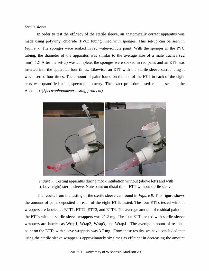
In order to test the efficacy of the sterile sleeve, an anatomically correct apparatus was
made using polyvinyl chloride (PVC) tubing lined with sponges. This set-up can be seen in
Figure 7. The sponges were soaked in red water-soluble paint. With the sponges in the PVC
tubing, the diameter of the apparatus was similar to the average size of a male trachea (22
mm).[12] After the set-up was complete, the sponges were soaked in red paint and an ETT was
inserted into the apparatus four times. Likewise, an ETT with the sterile sleeve surrounding it
was inserted four times. The amount of paint found on the end of the ETT in each of the eight
tests was quantified using spectrophotometry. The exact procedure used can be seen in the
Appendix (Spectrophotometer testing protocol).
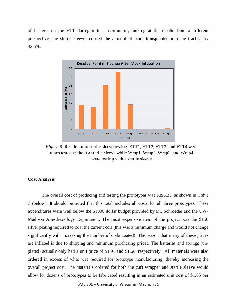
The results from the testing of the sterile sleeve can found in Figure 8. This figure shows
the amount of paint deposited on each of the eight ETTs tested. The four ETTs tested without
wrappers are labeled as ETT1, ETT2, ETT3, and ETT4. The average amount of residual paint on
the ETTs without sterile sleeve wrappers was 21.2 mg. The four ETTs tested with sterile sleeve
wrappers are labeled as Wrap1, Wrap2, Wrap3, and Wrap4. The average amount of residual
paint on the ETTs with sleeve wrappers was 3.7 mg. From these results, we have concluded that
using the sterile sleeve wrapper is approximately six times as efficient in decreasing the amount
Figure 7: Testing apparatus during mock intubation without (above left) and with
(above right) sterile sleeve. Note paint on distal tip of ETT without sterile sleeve
BME 301 – University of Wisconsin-Madison 21
of bacteria on the ETT during initial insertion or, looking at the results from a different
perspective, the sterile sleeve reduced the amount of paint transplanted into the trachea by
82.5%.
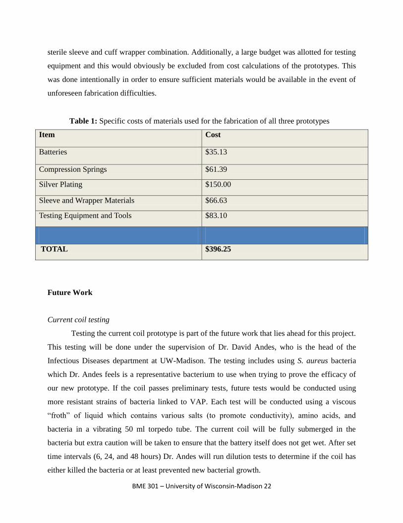
Cost Analysis
The overall cost of producing and testing the prototypes was $396.25, as shown in Table
1 (below). It should be noted that this total includes all costs for all three prototypes. These
expenditures were well below the $1000 dollar budget provided by Dr. Schroeder and the UW-
Madison Anesthesiology Department. The most expensive item of the project was the $150
silver plating required to coat the current coil (this was a minimum charge and would not change
significantly with increasing the number of coils coated). The reason that many of these prices
are inflated is due to shipping and minimum purchasing prices. The batteries and springs (un-
plated) actually only had a unit price of $1.91 and $1.68, respectively. All materials were also
ordered in excess of what was required for prototype manufacturing, thereby increasing the
overall project cost. The materials ordered for both the cuff wrapper and sterile sleeve would
allow for dozens of prototypes to be fabricated resulting in an estimated unit cost of $1.85 per
Figure 8: Results from sterile sleeve testing. ETT1, ETT2, ETT3, and ETT4 were
tubes tested without a sterile sleeve while Wrap1, Wrap2, Wrap3, and Wrap4
were testing with a sterile sleeve
BME 301 – University of Wisconsin-Madison 22
sterile sleeve and cuff wrapper combination. Additionally, a large budget was allotted for testing
equipment and this would obviously be excluded from cost calculations of the prototypes. This
was done intentionally in order to ensure sufficient materials would be available in the event of
unforeseen fabrication difficulties.
Item Cost
Batteries $35.13
Compression Springs $61.39
Silver Plating $150.00
Sleeve and Wrapper Materials $66.63
Testing Equipment and Tools $83.10
TOTAL $396.25
Future Work
Current coil testing
Testing the current coil prototype is part of the future work that lies ahead for this project.
This testing will be done under the supervision of Dr. David Andes, who is the head of the
Infectious Diseases department at UW-Madison. The testing includes using S. aureus bacteria
which Dr. Andes feels is a representative bacterium to use when trying to prove the efficacy of
our new prototype. If the coil passes preliminary tests, future tests would be conducted using
more resistant strains of bacteria linked to VAP. Each test will be conducted using a viscous
“froth” of liquid which contains various salts (to promote conductivity), amino acids, and
bacteria in a vibrating 50 ml torpedo tube. The current coil will be fully submerged in the
bacteria but extra caution will be taken to ensure that the battery itself does not get wet. After set
time intervals (6, 24, and 48 hours) Dr. Andes will run dilution tests to determine if the coil has
either killed the bacteria or at least prevented new bacterial growth.
Table 1: Specific costs of materials used for the fabrication of all three prototypes
BME 301 – University of Wisconsin-Madison 23
In addition to the various anti-microbial testing, further testing should be conducted to
verify and optimize the efficacy of the current coil. Tests should look to identify the optimal
current/voltage output and plating thicknesses to ensure the coil has a maximal antibacterial
effect. Also testing should be done with several other forms of bacteria liked to VAP in order to
identify any possible resistant strains. Finally, tests should be conducted using animal models
and eventually humans in order to recognize any possible health hazards associated with the
device.
Fabrication and patenting
Another area for future work is creating a more efficient way of producing the current
coils. The current method used to create the test coils required a non conductive epoxy to be used
in order to prevent the helices from touching. The design and fabrication of the insertion tool
helped to ensure a constant pitch between the helices but did nothing to address the ease of
connecting the coils to the current supply. Future designs should look to eliminate the time
consuming process of soldering the small current source onto the helical coil. In addition to this,
future models will require a suitable potting compound to ensure that the implanted battery will
not be affected by the presence of liquid mucus.
The placement of the current coil inside the ETT needs to be done quickly and with ease.
An area of work that can be done is creating a simple way for doctors or other medical personnel
to be able to take the current coil and promptly place it in the distal end of the ETT without any
difficulties. The current insertion tool needs to be modified to guarantee that the coil and tool are
matched in length so that the tool can provide uniform support to the coil during insertion. This
will help to prevent the coils ends from compressing and subsequently shorting out the circuit
during insertion.
Streamlining the production of both the cuff wrapper and sterile sleeve remain as the
prominent challenges associated with the two prototypes. Eliminating time consuming and error
producing steps such as gluing, taping, and cutting materials by hand will allow for consistent
and reproducible prototypes. Additionally, biocompatible materials must be utilized in all
situations as the prototypes are designed to have contact with the delicate tracheal mucosa cells.
Feedback from Dr. Schroeder and his colleagues about each of our products will be
collected before making any additional changes. This feedback will help direct our resources to
BME 301 – University of Wisconsin-Madison 24
the prototype or prototypes which are seen as the most practical ones for implementation in a
hospital setting. If any one of the prototypes is deemed to be successful at reducing bacteria and
can be implemented in hospitals, we will have a meeting with WARF, where we can present our
prototypes to them to check whether we have a patentable design.
BME 301 – University of Wisconsin-Madison 25
Conclusion
In conclusion, three successful prototypes were developed to help protect against
acquiring VAP during prolonged mechanical ventilation with a conventional ETT. Bench top
testing of the sterile sleeve showed an 82.5% reduction in simulated bacteria transfer from the
mouth to the trachea, while bench top testing of the cuff wrapper had a 100% success rate at
preventing simulated subglottic secretions from entering the lower airway. Future work includes
testing the current coil device in vitro to ensure it has anti-microbial effects as hypothesized,
continued in vitro and in vivo testing of the sterile sleeve and cuff wrapper, and streamlining the
production of biocompatible, ready to use products. All prototypes are preliminary designs that
are meant to prove a concept rather than being functionally complete designs. Patenting
prospects will also be pursued through WARF as all three prototypes are unique, novel ideas that
have the potential to thwart VAP.
BME 301 – University of Wisconsin-Madison 26
References
[1] Anderson, JM. "BIOLOGICAL RESPONSES TO MATERIALS." Annual Review of
Materials Research 31 (2001): 81-110. Print.
[2] Bouza, E., and A. Burillo. "Advance in the Prevention and Management of Ventilator-
associated Pneumonia." Current Opinion in Infectious Diseases 22 (2009): 345-51. Print.
[3] Broccard, A., and J. Marini. "Basic Mechanical Ventilation." Slideshare Present Yourself.
Society of Critical Care Medicine. Web.
[4] Chastre, J., and JY Fagon. "Ventilator-associated Pneumonia." Am J Respir Crit Care Med
165 (2002): 867-903. Print.
[5] Craven, DE, and KA Steger. "Epidemiology of Nosocomial Pneumonia: New Concepts on an
Old Disease." Chest 108 (1995): 1S-16S. Print.
[6] Furno, F., KS Morley, B. Wong, BL Sharp, PL Arnold, SM Howdle, R. Bayston, PD Brown,
PD Winship, and HJ Reid. "Silver Nanoparticles and Polymeric Medical Devices: A New
Approach to Prevention of Infection?" Antimicrob Chemother 54 (2004): 1019-024.
Print.
[7] Gehlbach, B., and J. Hall. "Overview of Mechanical Ventilation." Merck Manuals Online
Medica Library. Merk, Aug. 2007. Web. Feb. 2010.
<http://www.merck.com/mmpe/sec06/ch065/ch065b.html>.
[8] Kingshott, P., and H. Griesser. "Surfaces That Resist Bioadhesion." Current Opinion in Solid
State & Materials Science 4 (1999): 403-12. Print.
[9] Merriman, Harold L., Chris A. Hegyi, Cheryl R. Albright-Overton, John Carlos, and Robert
W. Putnam. "A Comparison of Four Electrical Stimulation Types on Staphylococcus."
Journal of Rehabilitation Research & Development 41.2(2004): 139-46.
[10] Merritt, K., A. Gaind, and JM Anderson. "Detection of Bacterial Adherence on Biomedical
Polymers." J Biomed Mater Res. 39 (1998): 415-22. Print.
[11] Neligan, P. "Mechanical Ventilation in Critical Care." Critical Care Medicine Tutorials.
CCM Tutorials.com. Web. <http://www.ccmtutorials.com/rs/mv/index.htm>.
[12] P. J. Young, M. Rollinson, G. Downward, and S. Henderson. “Leakage of fluid past the
tracheal cuff in a benchtop model”. British Journal of Anaesthesia 78 (1997): 557-562.
BME 301 – University of Wisconsin-Madison 27
[13] Pneumatikos, I., C. Dragoumanis, and D. Bouros. "Ventilator-associated Pneumonia of
Endotracheal Tube-associated Pneumonia?" Anesthesiology 110 (2009): 673-80. Print.
[14] Ramirez, P., Ferrer Miquel, and A. Torres. "Prevention Measures for Ventilator-associated
Pneumonia: a New Focus on the Endotracheal Tube." Current Opinion in Infectious
Diseases 20 (2007): 190-97. Print.
[15] Shorr, AF, M. Kollef, and MD Zilberberg. "Cost-effectiveness Analysis of a Silver-coated
Endotracheal Tube to Reduce the Incidence of Ventilator-associated Pneumonia." Infect
Control Hosp Epidemiol. 30 (2009): 759-63. Print.
[16] Spadaro,J.A., Berger,T.J., Barranco,S.D., Chapin,S.E., Becker,R.O. Antibacterial Effects of
Silver Electrodes with Weak Direct Current. American Society of Microbiology.Pg. 637
642.
[17] Tronstad, Leif, Martin Trope, and Benjamin F. Hammond. "Effect of Electric Current and
Silver Electrodes on Oral Bacteria." DEntal Traumatology 1.3 (2006): 112-15.
[18] Wagh, H., and D. Acharya. "Ventilator Associated Pneumonia ? an Overview." BJMP 2
(2009): 16-19. Print.
[19] Woske, HJ, T. Roding, I. Schulz, and H. Lode. "Ventilator-associated Pneumonia in a
Surgical Intensive Care Unit: Epidemiology, Etiology, and Comparison of Threee
Bronchoscopic Methods for Microbiological Specimen Sampling." Critical Care 5
(2001): 167-73. Print.
BME 301 – University of Wisconsin-Madison 28
Appendix
PDS
Function:
The aim of this project is to create an endotracheal tube (ETT), or an attachment to an
endotracheal tube, that effectively delivers air to an intubated patient while maintaining a sanitized
environment in the tracheal by reducing the formation of biofilms around the device. The
prevention of bacterial formation will be accomplished by integrating a combination of effective
biomaterials, anti-bacterial solutions, active sanitation systems and/or applying electrical current
to the device. In doing this, patient risks of developing ventilator associated pneumonia (VAP)
will be greatly reduced, increasing patient safety as well as costs of intubation.
Client Requirements:
Improve the design of current endotracheal tubes (ETT) in order to reduce the significant
risk factors associated with ventilator associated pneumonia (VAP). To be accomplished
by addressing some or all of the three improvement areas listed below:
o Improve the ETT’s cuff to eliminate the leakage of biofilms into the lungs.
o Create and maintain a sterile environment above the ETT cuff.
o Reduce or eliminate formation of biofilms on ETT walls.
Build a preliminary prototype for under $1000.
Prototype can be either an add-on to currently used ETTs (most desirable) or an entirely
new ETT.
If reusable prototype must be compatible with hospital sterilization practices (MetriCide
cleaning solution).
Prototype must be safe for the patient and compatible with trachea endothelia cells.
Obtain some preliminary data in order to prove antibacterial capabilities of the prototype.
If possible reduce the pressure on the vocal cords associated with intubation.
1. Physical and Operational Characteristics
a.) Performance requirement: The ETT should reduce the risk of patient acquiring VAP
or other noscomial infections through both passive and active defense mechanisms.
BME 301 – University of Wisconsin-Madison 29
Passive elements include bioadhesive resistant materials, antibiotics, silver embedded
foams, and/or semi-viscous gels. Active elements include suctioning and lavage devices,
UV sterilization methods, low dose electrical current, and/or any other user input required
mechanism of sterilization.
b.) Safety: The ETT will be used in vivo and thus must meet all safety standards to
ensure no adverse effects on the body. It should reliably prevent VAP formation while
maintaining its primary function as an advanced airway.
c.) Accuracy and Reliability: The ETT should not prevent airflow to the patient. See
Safety section above.
d.) Life in Service: Prolonged intubation (>48 hrs) greatly increases the risk of acquiring
VAP so the ETT should be expected to be in situated within the trachea for a minimum of
48 hours for as long as the patient is intubated. ETT’s are single-use and disposable.
e.) Shelf Life: A sterile environment shelf life of at least 5 years.
f.) Operating Environment:
g.) Ergonomics: The device should allow for intubation in a similar manner to existing
ETT’s. In addition, the geometry of the new ETT should be made to prevent any damage
to the vocal cords, trachea, or any other part of the advanced airway.
h.) Size: ETT’s range from 2-10.5 mm internal diameter, however the cuff of the ETT
also needs to be compact enough to prevent damage to the vocal cords as it passes
through the trachea.
i.) Weight: Weight should be comparable to the weight of current ETT’s on the market.
j.) Materials: Current ETT’s are made of polyvinyl chloride (PVC) medical tubing with
a polyethylene (PE) cuff. All plastics, gels, foams, or metals used in the new device
should be medically safe, FDA approved, and non-toxic.
2 Production Characteristics
a.) Quantity: One prototype ETT is the goal for this semester.
b.) Target Production Cost: A cost effective analysis of reduction of VAP using silver
salt coated ETT’s indicated that a break-even point for ETT cost is $388 per tube when
VAP is prevented [2]. This should be set as a maximal per tube cost for a final end
product.
BME 301 – University of Wisconsin-Madison 30
3. Miscellaneous
a.) Standards and Specifications: FDA approval would be required before the
product could be used in vivo
b.) Consumer: Medical practitioners and hospitals will be the primary consumer of our
device however the ETT will be designed for patient intubation.
c.) Patient-Related Concerns: Sanitization of the trachea and surrounding airway is
crucial in preventing the onset of VAP in patients. All defensive mechanism must be
FDA approved prior to use in vivo.
d.) Competition: At this time, there are many different ETT’s on the market, but none
of them incorporate all of the ideas and solutions that our design would incorporate.
References
[1] Groot AJ, Geubbels EL, Beaumont MT, Wille JC, Boer AS. [Hospital infections and risk
factors in the intensive care units of 16 Dutch hospitals, results of surveillance of quality
assurance indicators]. Ned Tijdschr Geneeskd. 2001 Jun 30; 145(26): 1249-54.
[2] Shorr AF, Zilberberg MD, Kollef M. Cost-effectiveness analysis of a silver-coated
endotracheal tube to reduce the incidence of ventilator-associated pneumonia. Infection
Control Hospital Epidemiology. 2009 Aug; 30(8): 759-63.
Fluid leakage testing protocol
Introduction
Mucus-like secretions and saliva pooled in the trachea along the endotracheal tube (ETT)
and above the inflatable high volume low pressure (HVLP) cuff is a highly effective route of
bacterial entry into the lungs. Aspiration of these pooled secretions past an HVLP cuff has been
well documented as a primary cause of VAP during prolonged mechanical ventilation.[ 2,3]
Thick secretions are difficult to remove through conventional means (thin suction tubing) and are
continually secreted by tissues in the oropharynx and trachea as a means of lubrication.
Longitudinal folds almost always form in conventional HVLP cuffs due to shear and
compressive forces from the trachea walls. To avoid damaging the trachea mucosa the pressure
BME 301 – University of Wisconsin-Madison 31
in the ETTs HVLP cuff must be kept below 30 cm H2O and thus a full trachea-cuff seal is
impossible.[1]
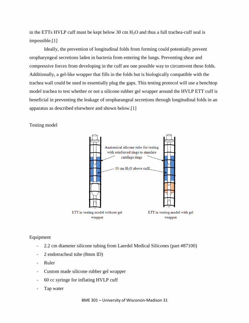
Ideally, the prevention of longitudinal folds from forming could potentially prevent
oropharyngeal secretions laden in bacteria from entering the lungs. Preventing shear and
compressive forces from developing in the cuff are one possible way to circumvent these folds.
Additionally, a gel-like wrapper that fills in the folds but is biologically compatible with the
trachea wall could be used to essentially plug the gaps. This testing protocol will use a benchtop
model trachea to test whether or not a silicone rubber gel wrapper around the HVLP ETT cuff is
beneficial in preventing the leakage of oropharangeal secretions through longitudinal folds in an
apparatus as described elsewhere and shown below.[1]
Testing model
Equipment
- 2.2 cm diameter silicone tubing from Laerdel Medical Silicones (part #87100)
- 2 endotracheal tube (8mm ID)
- Ruler
- Custom made silicone rubber gel wrapper
- 60 cc syringe for inflating HVLP cuff
- Tap water
BME 301 – University of Wisconsin-Madison 32
Procedure
1. Each series of steps will be repeated for an ETT with and without a gel wrapper
2. Insert ETT into silicone testing apparatus and inflate HVLP cuff with 10 mL of air using
a 60 cc syringe. This will act to simulate the 20-30 cm H2O pressure exerted against the
trachea wall in a typical intubation procedure
3. With ETT secured in tube, fill with a 10 cm column of colored H2O (“subglottic
secretions). Affix a ruler near the silicone tube to allow measurements to be made on the
liquid column
4. After 20 minutes record final water level and repeat experiment as necessary
Conclusion
The results of this test will indicate whether or not a silicone rubber gel wrapper around
the ETTs inflatable cuff will prevent the leakage of subglottic secretions from the trachea and
oropharyngeal region into the lower airway (bronchi and lungs).
Sources
[1] P. J. Young, M. Rollinson, G. Downward, and S. Henderson. “Leakage of fluid past the
tracheal cuff in a benchtop model”. British Journal of Anaesthesia 78 (1997): 557-562.
[2] Pneumatikos, I., C. Dragoumanis, and D. Bouros. "Ventilator-associated Pneumonia of
Endotracheal Tube-associated Pneumonia?" Anesthesiology 110 (2009): 673-80. Print.
[3] Ramirez, P., Ferrer Miquel, and A. Torres. "Prevention Measures for Ventilator-associated
Pneumonia: a New Focus on the Endotracheal Tube." Current Opinion in Infectious
Diseases 20 (2007): 190-97. Print.
Spectrophotometer testing protocol
Introduction
The transfer and/or implantation of endogenous oral bacteria into the trachea mucosa has
been linked to the occurrence of ventilator associated pneumonia (VAP) in patients intubated
with an endotracheal tube (ETT).[1,4,5] While intubation is often a life-saving procedure, the act
of inserting an ETT in the trachea can lead to trauma of the delicate mucosa which normally acts
BME 301 – University of Wisconsin-Madison 33
as a protective host defense mechanism; the trachea mucosa secretes mucus to trap pathogens
and particulates, is dense in phagocytoic alveolar macrophages, and is lined with cilia that sweep
in an upward fashion to move mucus from the larynx up into the pharynx (cilliary escalator).[2]
By reducing the transfer of opportunistic bacteria from the upper airway (oral cavity and
pharynx) into the lower airway (trachea and bronchi) the potential of eliminating or delaying the
onset of VAP could be dramatically increased. This testing procedure will help to elucidate the
efficacy of a “sterile wrapper” modular add-on to currently existing ETTs.
Spectrophotometry can be used to determine the concentration of a substance (or
substances) based upon the principle of absorbance. For this test a CHEM2000
Spectrophotometer (PC2000 PC Plug-in Fiber Optic Spectrometer, a tungsten–halogen light
source with integrated cuvette holder, an optical fiber, and operating software) will be used to
determine the concentration of a single solution of red, water soluble paint and tap water. In
spectrophotometry, a multiple wavelength light source illuminates a sample that is placed in a
cuvette. Not all of the light shone on the sample is transmitted through the sample, but the light
that is able to pass through is collected and sent to a spectrometer (all wavelengths are
transmitted through the sample in differing amounts) via a fiber. An ADC is used to convert the
analog data into a digital signal that is displayed on a computer screen. Every substance has a
characteristic absorptivity that is unique to the particles in the substance and thus light is
absorbed in varying amounts depending upon both the substance and the wavelength of the light
used in the spectrophotometry test. This protocol will use red paint to represent oral bacteria in
an anatomically correct testing model as depicted below.
BME 301 – University of Wisconsin-Madison 34
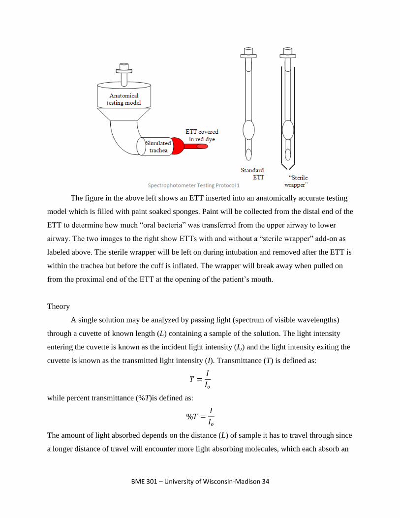
The figure in the above left shows an ETT inserted into an anatomically accurate testing
model which is filled with paint soaked sponges. Paint will be collected from the distal end of the
ETT to determine how much “oral bacteria” was transferred from the upper airway to lower
airway. The two images to the right show ETTs with and without a “sterile wrapper” add-on as
labeled above. The sterile wrapper will be left on during intubation and removed after the ETT is
within the trachea but before the cuff is inflated. The wrapper will break away when pulled on
from the proximal end of the ETT at the opening of the patient’s mouth.
Theory
A single solution may be analyzed by passing light (spectrum of visible wavelengths)
through a cuvette of known length (L) containing a sample of the solution. The light intensity
entering the cuvette is known as the incident light intensity (Io) and the light intensity exiting the
cuvette is known as the transmitted light intensity (I). Transmittance (T) is defined as:
𝑇 =𝐼
𝐼𝑜
while percent transmittance (%T)is defined as:
%𝑇 =𝐼
𝐼𝑜
The amount of light absorbed depends on the distance (L) of sample it has to travel through since
a longer distance of travel will encounter more light absorbing molecules, which each absorb an
BME 301 – University of Wisconsin-Madison 35
equal amount of light at a given wavelength. Thus the unit length (Lo) is inversely proportional to
the concentration (C) of the sample. This relationship is expressed as:
𝐿𝑜 =1
𝑎𝐶
where a is a constant unique to the solution being tested.
Using the above relationships a substitution can be made as follows:
𝑇 = 10−(𝐿 𝐿𝑜 ) = 10−𝐿𝑎𝐶
which is also used as the Beer-Lambert Law (logarithmic function of transmittance; absorbance
(A)) defined as:
𝐴 = 𝐿𝑎𝐶 = −log(𝑇)
where the constant a is further designated as the molar extinction coefficient or absorptivity of
the solution and is unique to the solution being tested as a function of wavelength.[3]
Equipment
- Anatomically correct trachea model (PVC pipes)
- Sponge cut to fit in model and fill in dead space
- Red, water soluble craft paint
- Endotracheal tubes (6)
- Analytical balance
- Beaker or graduated cylinder
- CHEM2000 Spectrophotometer (PC2000 PC Plug-in Fiber Optic Spectrometer, a
tungsten–halogen light source with integrated cuvette holder, an optical fiber, and
operating software)
- Clean cuvette
- Kimwipes and paper towels
- 3-5 “sterile wrapper” prototypes
- Tap water (200 mL per test)
- Prepared stock solution of known paint concentration. Specific concentration does not
matter; it will solely be used as a comparison to what is collected off the distal end of the
test ETTs
BME 301 – University of Wisconsin-Madison 36
Procedure
Stock solution
1. Prepare stock solution of known concentration paint and water mixture. Concentration
units may be arbitrary (i.e., w drops per x mL or y grams per z mL) but it is important to
record specifically how much water was used (mL) and how much paint was used (drops
or grams)
2. Create serial dilutions of stock solution as this will be used for a standard curve to
determine unknown solution concentrations
Initial preparations
1. Plug in CHEM2000 Spectrophotometer and allow lamp to warm up for 20-30 minutes
2. With an empty cuvette in the sample slot take a reference spectrum (in scope mode) by
clicking store reference spectrum
3. Completely block the light source (in scope mode) and take a dark spectrum by clicking
store dark spectrum. Note if any program parameters are changed (i.e., integration time)
repeat steps 2 and 3.
4. Fill cuvette with prepared stock solution. Click the absorbance mode icon and save the
spectrum with the save icon. Repeat for all dilutions
5. Soak sponge cut outs in red paint and place in testing apparatus just prior to next set of
steps (below)
ETT tests
1. Using a standard ETT, mock intubate the PVC testing model (filled with paint soaked
sponge) and inflate distal cuff. Take a picture of the distal end of the ETT. Deflate cuff
and remove extension fake trachea from testing apparatus
2. Using a predetermined volume of warm tap water (volume must be constant for all tests
or recorded if different; suggest 100 mL), quickly wash distal end of cuff and extension
tube to remove all paint transferred from testing apparatus
3. Fill cuvette with sample of water from step 2 above, click the absorbance mode icon, and
save the spectrum with the save icon
BME 301 – University of Wisconsin-Madison 37
4. Repeat steps 1-3 at least three times for each condition being tested (“sterile wrapper” or
standard endotracheal tube). Add paint before each new step 1 is repeated
5. Analyze data using Microsoft excel or MatLab to determine quantity of paint transferred
to distal end of the ETT for each condition
Conclusion
The results of this test will indicate whether or not a “sterile wrapper” addition to current
intubation protocols is a viable means of reducing the transfer of endogenous oral bacteria to the
trachea mucosa which has the potential to reduce the alarming incidence of ventilator associated
pneumonia in ICU and ER settings.
Sources
[1] Bouza, E., and A. Burillo. "Advance in the Prevention and Management of Ventilator-
associated Pneumonia." Current Opinion in Infectious Diseases 22 (2009): 345-51.
Print.
[2] Craven, DE, and KA Steger. "Epidemiology of Nosocomial Pneumonia: New Concepts on an
Old Disease." Chest 108 (1995): 1S-16S. Print.
[3] John G. Webster. BME 310 Lab 4 Pressure Sensors & Ultrasonic Flowmeter. February 26,
2007. UW-Madison
[4] Ramirez, P., Ferrer Miquel, and A. Torres. "Prevention Measures for Ventilator-associated
Pneumonia: a New Focus on the Endotracheal Tube." Current Opinion in Infectious
Diseases 20 (2007): 190-97. Print.
[5] Woske, HJ, T. Roding, I. Schulz, and H. Lode. "Ventilator-associated Pneumonia in a
Surgical Intensive Care Unit: Epidemiology, Etiology, and Comparison of Threee
Bronchoscopic Methods for Microbiological Specimen Sampling." Critical Care 5
(2001): 167-73. Print.