endura az20 series probe combustion oxygen monitor ... · combustion gas analyzers from abb. the...
TRANSCRIPT

User Guide IM/AZ20P–EN Rev. D
Endura AZ20 series probeCombustion oxygen monitor
Superior technology andquality from the world leaderin oxygen measurement
Introduction
The Endura AZ20 is the latest in a long line of high-quality,combustion gas analyzers from ABB.
The sensor, based on a zirconium oxide cell, is mounted at the tipof the probe that is inserted in the flue duct. The resulting direct,in situ measurement provides accurate and rapid oxygen readingfor combustion control / optimization and emissions monitoringpurposes.
Endura AZ20 has been designed for extended periods ofmaintenance-free operation. The modular design with reducedcomponent count improves the reliability and robustness of thesystem and simplifies breakdown repair if it occurs.
Kits containing all the parts needed to complete on-site repairs areavailable from ABB, ensuring that service personnel can effectrepairs quickly and efficiently at minimum cost. The Endura AZ20probe has retained an easy-access cell arrangement, similar to theproven ZFG2 probe. This ensures cell replacement can be carriedout on-site using readily available, basic hand tools, even after longperiods of high temperature operation.
This User Guide should be used in conjunction with thefollowing publications:
— Transmitter User Guide (IM/AZ20E–EN)
— Maintenance Guide (IM/AZ20M–EN)

The CompanyWe are an established world force in the design and manufacture of measurement products for industrial process control, flowmeasurement, gas and liquid analysis and environmental applications.
As a part of ABB, a world leader in process automation technology, we offer customers application expertise, service and supportworldwide.
We are committed to teamwork, high quality manufacturing, advanced technology and unrivalled service and support.
The quality, accuracy and performance of the Company's products result from over 100 years experience, combined with acontinuous program of innovative design and development to incorporate the latest technology.

Endura AZ20 series probeCombustion oxygen monitor Contents
IM/AZ20P–EN Rev. D 1
Contents
1 Safety ...............................................................................21.1 Health & Safety ........................................................21.2 Electrical Safety – CEI / IEC 61010-1:2001-2 ...........21.3 Symbols – CEI / IEC 61010-1:2001-2 ......................21.4 Product Recycling Information ..................................31.5 Product Disposal ......................................................31.6 Restriction of Hazardous Substances (RoHS) ..........41.7 Safety Precautions ...................................................41.8 Safety Conventions ..................................................41.9 Safety Recommendations ........................................41.10 Service and Repairs .................................................41.11 Potential Safety Hazards ..........................................4
2 System Overview ............................................................5
3 Mechanical Installation ...................................................63.1 General Installation Requirements ............................63.2 Unpacking ................................................................63.3 Identifying the Probe ................................................63.4 Siting ........................................................................7
3.4.1 System Overview ..........................................73.5 Pneumatic Connections ...........................................8
3.5.1 Pneumatic Connection Configurations ..........83.5.2 Pneumatic Connections for
Probes with Restrictors .................................93.5.3 Pneumatic Connections for
Probes without Restrictors ..........................103.6 Overall Dimensions .................................................11
3.6.1 Remote Endura AZ20 Probe .......................113.6.2 Integral Endura AZ20 Probe ........................11
3.7 Endura AZ20 Probe Flanges – All Probe Lengths ...123.8 Mounting Plates for ABB Standard Flanges ............13
3.8.1 0.5 m (1.7 ft) Probe – Part No. AZ200 796 ..133.8.2 1.0 to 4.0 m (3.3 to 13.1 ft) Probes –
Part No. AZ200 795 ....................................133.8.3 Long Probe to 0.5 m (1.7 ft) Probe Adaptor
Plate – Part No. AZ200 794 ........................133.9 Mounting ................................................................14
3.9.1 Probe .........................................................143.9.2 0.5 m (1.64 ft) Probe to
Large Probe Adapter Plate Mounting ..........153.10 End of Life Disposal ...............................................163.11 Endura AZ20 Probe and
Transmitter Weights (Unpacked and Packed) .........16
4 Connections .................................................................. 174.1 Electrical Safety ..................................................... 174.2 Cable Preparation .................................................. 18
4.2.1 Endura AZ20 Probe toRemote Endura AZ20 Transmitter .............. 18
4.3 Electrical Connections ........................................... 204.3.1 Endura AZ20 Probe
Transmitter Connections ............................ 204.3.2 AutoCal Connections at
Endura AZ20 Probe .................................... 214.4 Gas and Air Connections ....................................... 22
4.4.1 Restrictors .................................................. 224.4.2 Connection Types ...................................... 224.4.3 Orientation of External Connections ........... 224.4.4 Test Gas Inlets ........................................... 234.4.5 Vent ........................................................... 244.4.6 Reference Air Inlet ...................................... 244.4.7 Inline Shut-off Valves .................................. 244.4.8 Internal Test Gas and Reference Air Tubes . 25
5 Start-up and Operation ................................................ 265.1 Preparation ............................................................ 265.2 Setting Up Test Gases ........................................... 26
5.2.1 AutoCal System with Restrictors ................. 265.2.2 AutoCal System without Restrictors ............ 275.2.3 Non-AutoCal System with Restrictors ......... 275.2.4 Non-AutoCal System without Restrictors .... 27
6 Endura AZ20 Probe Specification ................................ 28
Appendix A – Principle of Operation ................................ 29
Appendix B – Endura AZ20/ZFG2 Replacement Probe .. 30B.1 Endura AZ20/ZFG2 Replacement
Probe Conduit Electrical Connections .................... 31B.1.1 Electrical Connections ................................ 31B.1.2 Endura AZ20/ZFG2 Replacement Probe –
Conduit Reference Air Connections ............ 32B.2 ZDT-FG Analyzer Connections ............................... 33
B.2.1 Disconnecting the Existing ZFG2 Probe ...... 33B.2.2 Connecting the
Endura AZ20/ZFG2 Replacement Probe .... 33B.3 ZMT Transmitter Connections ................................ 34
B.3.1 Disconnecting the Existing ZFG2 Probe ...... 34B.3.2 Connecting the
Endura AZ20/ZFG2 Replacement Probe .... 34
Appendix C – Using an ExternalAutomatic Calibration Panel .............................................. 35
Appendix D – Accessories and Spares ........................... 36D.1 Documentation ...................................................... 36D.2 Probe Spares ........................................................ 36

Endura AZ20 series probeCombustion oxygen monitor 1 Safety
2 IM/AZ20–EN Rev. D
1 SafetyInformation in this manual is intended only to assist ourcustomers in the efficient operation of our equipment. Use ofthis manual for any other purpose is specifically prohibited andits contents are not to be reproduced in full or part without priorapproval of the Technical Publications Department.
1.1 Health & Safety
1.2 Electrical Safety – CEI / IEC 61010-1:2001-2This equipment complies with the requirements of CEI / IEC61010-1:2001-2 'Safety Requirements for Electrical Equipmentfor Measurement, Control and Laboratory Use' and complieswith US NEC 500, NIST and OSHA.
If the equipment is used in a manner NOT specified by theCompany, the protection provided by the equipment may beimpaired.
1.3 Symbols – CEI / IEC 61010-1:2001-2One or more of the following symbols may appear on theequipment labelling:
Health and Safety
To ensure that our products are safe and without risk tohealth, the following points must be noted:
The relevant sections of these instructions must beread carefully before proceeding.
Warning labels on containers and packages must beobserved.
Installation, operation, maintenance and servicingmust only be carried out by suitably trained personneland in accordance with the information given.
Normal safety precautions must be taken to avoid thepossibility of an accident occurring when operating inconditions of high pressure and / or temperature.
Chemicals must be stored away from heat, protectedfrom temperature extremes and powders kept dry.Normal safe handling procedures must be used.
When disposing of chemicals ensure that no twochemicals are mixed.
Safety advice concerning the use of the equipmentdescribed in this manual or any relevant Material SafetyData Sheets (where applicable) may be obtained from theCompany address on the back cover, together withservicing and spares information.
Protective earth (ground) terminal.
Functional earth (ground) terminal.
Direct current supply only.
Alternating current supply only.
Both direct and alternating current supply.
The equipment is protected through doubleinsulation.
This symbol, when noted on a product, indicates apotential hazard which could cause seriouspersonal injury and / or death.The user should reference this instruction manualfor operation and / or safety information.
This symbol, when noted on a product enclosure orbarrier, indicates that a risk of electrical shock and /or electrocution exists and indicates that onlyindividuals qualified to work with hazardousvoltages should open the enclosure or remove thebarrier.
This symbol indicates that the marked item can behot and should not be touched without care.

Endura AZ20 series probeCombustion oxygen monitor 1 Safety
IM/AZ20–EN Rev. D 3
1.4 Product Recycling Information
1.5 Product Disposal
This symbol indicates the presence of devicessensitive to electrostatic discharge and indicatesthat care must be taken to prevent damage tothem.
This symbol identifies a risk of chemical harm andindicates that only individuals qualified and trainedto work with chemicals should handle chemicals orperform maintenance on chemical delivery systemsassociated with the equipment.
This symbol indicates the need for protective eyewear.
This symbol indicates the need for protective handwear.
Electrical equipment marked with this symbol maynot be disposed of in European public disposalsystems. In conformity with European local andnational regulations, European electrical equipmentusers must now return old or end-of-life equipmentto the manufacturer for disposal at no charge to theuser.
Products marked with this symbol indicates that theproduct contains toxic or hazardous substances orelements. The number inside the symbol indicatesthe environmental protection use period in years.
Electrical equipment marked with this symbolmay not be disposed of in European publicdisposal systems after 12 August 2005. Inconformity with European local and nationalregulations (EU Directive 2002 / 96 / EC),European electrical equipment users must nowreturn old or end-of-life equipment to themanufacturer for disposal at no charge to theuser.
Note. For return for recycling, please contact theequipment manufacturer or supplier for instructions on howto return end-of-life equipment for proper disposal.
Note. The following only applies to European customers.
ABB is committed to ensuring that the risk ofany environmental damage or pollution causedby any of its products is minimized as far aspossible. The European Waste Electrical andElectronic Equipment (WEEE) Directive (2002 /96 / EC) that came into force on August 132005 aims to reduce the waste arising fromelectrical and electronic equipment; andimprove the environmental performance of allthose involved in the life cycle of electrical andelectronic equipment.
In conformity with European local and nationalregulations (EU Directive 2002 / 96 / EC statedabove), electrical equipment marked with theabove symbol may not be disposed of inEuropean public disposal systems after 12August 2005.

Endura AZ20 series probeCombustion oxygen monitor 1 Safety
4 IM/AZ20–EN Rev. D
1.6 Restriction of Hazardous Substances (RoHS)
1.7 Safety PrecautionsPlease read the entire manual before unpacking, setting up, oroperating this instrument.
Pay particular attention to all warning and caution statements.Failure to do so could result in serious injury to the operator ordamage to the equipment.
To ensure the protection provided by this equipment is notimpaired, do not use or install this equipment in any mannerother than that which is specified in this manual.
1.8 Safety Conventions
1.9 Safety RecommendationsFor safe operation, it is imperative that these service instructionsbe read before use and that the safety recommendationsmentioned herein be scrupulously respected. If danger warningsare not heeded to, serious material or bodily injury could occur.
1.10 Service and RepairsOther than the serviceable items listed in Appendix D, page 36,none of the instrument's components can be serviced by theuser. Only personnel from ABB or its approved representative(s)is (are) authorized to attempt repairs to the system and onlycomponents formally approved by the manufacturer should beused. Any attempt at repairing the instrument in contravention ofthese principles could cause damage to the instrument andcorporal injury to the person carrying out the repair. It rendersthe warranty null and void and could compromise the correctworking of the instrument and the electrical integrity or the CEcompliance of the instrument.
If you have any problems with installation, starting, or using theinstrument please contact the company that sold it to you. If thisis not possible, or if the results of this approach are notsatisfactory, please contact the manufacturer's CustomerService
1.11 Potential Safety HazardsThe following potential safety hazards are associated withoperating the system:
Electrical (line voltage)
Probe weight
The European Union RoHS Directive andsubsequent regulations introduced in memberstates and other countries limits the use of sixhazardous substances used in themanufacturing of electrical and electronicequipment. Currently, monitoring and controlinstruments do not fall within the scope of theRoHS Directive, however ABB has taken thedecision to adopt the recommendations in theDirective as the target for all future productdesign and component purchasing. .
Warning. In this manual, a warning is used to indicate acondition which, if not met, could cause serious personalinjury and / or death. Do not move beyond a warning until allconditions have been met.
If a warning sign appears on the instrument itself, refer toPrecautionary Labels – UL Certification and Electrical Safety– CEI / IEC 61010-1:2001-2 for an explanation.
Caution. A caution is used to indicate a condition which, ifnot met, could cause minor or moderate personal injury and/ or damage to the equipment. Do not move beyond acaution until all conditions have been met.
Note. A note is used to indicate important information orinstructions that should be considered before operating theequipment.
����
Warning. The installation of the instrument should beperformed exclusively by personnel specialized andauthorized to work on electrical installations, in accordancewith relevant local regulations.

Endura AZ20 series probeCombustion oxygen monitor 2 System Overview
IM/AZ20–EN Rev. D 5
2 System OverviewThis User Guide provides the following information:
schematics for systems fitted with or without restrictors(including test gas and reference air requirements) – seesection 3.3, page 6 for product identification
installation details for integral and remote Endura AZ20probes – see section 3, page 6
electrical connection details:
– for standard probe connection details (withoutautomatic calibration [AutoCal]) between a remoteEndura AZ20 probe and a remote Endura AZ20transmitter – see section 4.3.1, page 20
– for automatic calibration connection details betweena remote Endura AZ20 probe and a remote EnduraAZ20 transmitter – see section 4.3.2, page 21
electrical connection details between an existing ZDTanalyzer or ZMT transmitter and a remote EnduraAZ20/ZFG2 replacement probe (where the EnduraAZ20/ZFG2 replacement probe replaces an existing ZFG2probe)
– refer to appendix B.2, page 33 for ZDT-FGconnections
– refer to appendix B.3, page 34 for ZMT connections
The Endura AZ20 oxygen probe measures oxygenconcentration in flue gas using an in situ 'wet analysis' method.The 'wet analysis' method avoids measurement error (typically20% of reading higher than the actual value) that is introducedby a sampling system using the 'dry analysis' method.
For customers with an existing installed ZFG2 probe with a ZMTor ZDT transmitter, a 55 V heater version of the Endura AZ20probe (the Endura AZ20 / ZFG2 replacement probe) is available.
System equipment comprises a (flue-mounted) Endura AZ20probe controlled by an integral or remote transmitter. Duringoperation, a zirconia cell within the probe is held at a constanttemperature of 700°C (1292 °F) by a probe heater and controlthermocouple assembly. If the heater control circuitry orsoftware fails (unsafe), the probe heater power supply isswitched off, ensuring the system fails 'safe' and protects theheater from an over-temp failure.
An output generated at the zirconia cell is processed in thetransmitter giving a locally displayed O2 reading and a 4 to 20mA retransmission signal over any range between 0 % and 100% O2.
Optional automatic calibration (AutoCal*) enables automatic,semi-automatic or manual calibration to be performed using aprobe-mounted gas control manifold mounted within the probehead. Calibration sequencing is software-controlled from thetransmitter.
Optional restrictors (where fitted*) in the probe head control thetest gas and reference air flow without the need for flowmeters.The probe requires only preset test gas and reference airpressures of 1 bar (15 psi) to maintain a constant flow of 2.2 l /min (4.662 scfh). This flow is not affected by changes in themeasured gas pressure of ± 0.35 bar (5 psi).
*Not available for Endura AZ20/ZFG2 replacement probes.
Warning.
System configuration must be carried out only by usersor personnel with approved access rights (userprivileges).
Read all relevant sections of this guide beforeconfiguring the system or modifying systemparameters.
Install and use this equipment as detailed in this guide.Install and use associated equipment in accordancewith the relevant national and local standards.
Warning. Endura AZ20 probes must be connected only toan integral or remote Endura AZ20 transmitter (AZ20XX1or 2).Endura AZ20/ZFG2 replacement probes (AZ200002) mustbe connected only to a ZDT-FG or ZMT transmitter.
Endura AZ20 series probeCombustion oxygen monitor 3 Mechanical Installation
6 IM/AZ20–EN Rev. D
3 Mechanical Installation3.1 General Installation Requirements
3.2 Unpacking
3.3 Identifying the ProbeEach probe is identified by 2 probe-specific labels attached tothe probe head (separate transmitter-specific labels are alsoattached to each system transmitter).
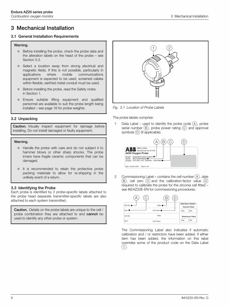
The probe labels comprise:
1 Data Label – used to identify the probe code A, probeserial number B, probe power rating C and approvalsymbolsD (if applicable).
2 Commissioning Label – contains the cell numberA, dateB, cell zero C and the calibration factor value Drequired to calibrate the probe for the zirconia cell fitted –see IM/AZ20E-EN for commissioning procedures.
The Commissioning Label also indicates if automaticcalibration and / or restrictors have been added. If eitheritem has been added, the information on this labeloverrides some of the product code on the Data Label1.
Warning.
Before installing the probe, check the probe data andthe alteration labels on the head of the probe – seeSection 3.3.
Select a location away from strong electrical andmagnetic fields. If this is not possible, particularly inapplications where mobile communicationsequipment is expected to be used, screened cableswithin flexible, earthed metal conduit must be used.
Before installing the probe, read the Safety notesin Section 1.
Ensure suitable lifting equipment and qualifiedpersonnel are available to suit the probe length beinginstalled – see page 16 for probe weights.
Caution. Visually inspect equipment for damage beforeinstalling. Do not install damaged or faulty equipment.
Warning.
Handle the probe with care and do not subject it tohammer blows or other sharp shocks. The probeinners have fragile ceramic components that can bedamaged.
It is recommended to retain the protective probepacking materials to allow for re-shipping in theunlikely event of a return.
Caution. Details on the probe labels are unique to the cell /probe combination they are attached to and cannot beused to identify any other probe or system.
Fig. 3.1 Location of Probe Labels
��������
��������������� ����
�� �
��
���������� ����
������������ �������������
����� ���������������������������� ��� ���������!��""�#� ���$�%��&��'(�)��!�*+(����,���-
.����/0��1�����2 �������� �3�
��
��� ��� �
����
���
� ��

Endura AZ20 series probeCombustion oxygen monitor 3 Mechanical Installation
IM/AZ20–EN Rev. D 7
3.4 SitingAvoid locations where:
obstructions or bends create turbulence in the gas flowand / or hinder probe insertion and removal
vibration induced by other plant or vortex shedding ispresent
the probe may be subject to shock loading, for example,close to ash hammers
If excessive abrasive dust is present, fit a protective shield alongthe whole length of the inserted probe section.
If liquid condensation is present or could be created (forexample a cold start on a gas boiler), mount the probe at adownward angle to prevent water entering the cell.
If necessary, thermally lag the probe mounting flange and bodyto prevent acid dew-point corrosion and to maintain the probehead temperature within the range of –20 to 70 °C (4 to 176 °F).
3.4.1 System Overview
Fig. 3.2 Probe and Transmitter Temperature / Environmental Limits and Power Input / Output Supplies
55 °C(131 °F)
IP66 (NEMA 4X)
–20 °C(–4 °F)
–20 °C(–4 °F)
*Flue
0.5 to 4 m(1.7 to 13.1 ft.)
800 °C (1472 °F)
IP66 (NEMA 4)
IP66 (NEMA 4)
70 °C(158 °F)
–20 °C(–4 °F)
Mains Supply
Relays
Output Signals
Probe with Integral Transmitter**
Probe with Remote Transmitter**
20 mm or1/2 in. NPT
Gland
Endura AZ20 Probe Cable (ABB Supplied) – Max. 100 m (300 ft.)
Mains Supply
Relays Output Signals
*Can withstand 35 kPa (5.1 psi) – positive or negative (pressure compensation required above 5 kPa [0.7 psi] – transmitter can supply fixedpressure compensation)
**Transmitter does not contain a reference air supply for the probe.
55 °C(131 °F)
–20 °C(–4 °F)

Endura AZ20 series probeCombustion oxygen monitor 3 Mechanical Installation
8 IM/AZ20–EN Rev. D
3.5 Pneumatic Connections
3.5.1 Pneumatic Connection ConfigurationsRefer to the pneumatic configuration flowchart (Fig. 3.3) below to identify which system configuration is the closest match for yourcomponents and then refer to the relevant figure in Section 3.5.2, page 9 or 3.5.3, page 10 for pneumatic settings.
Caution.
The configuration option of having flow restrictors fitted to the probe determines the way the reference air and test gas flowis controlled. Ensure the instructions for the pneumatic connections are followed accurately – an incorrect configuration atthe probe can cause errors and / or permanent damage.
All configurations – do not use gas mixers online to supply test gases to the probe(s) unless it can be confirmed thaterrors are not introduced by the high delivery pressures required to the probe(s).
Probes with restrictors – the reference air and test gas flow is regulated by the restrictors installed in the probe whichrequire a set pressure of 1 bar (15 psi) to deliver the correct flows. Because the gases are delivered as a pressure at theprobe it is permissible to use parallel pipework for multiple-probe installations.
Probes without restrictors – the reference air and test gas flow is regulated by flowmeters (with integral needle valves)fitted in the delivery lines to the sensor – one flowmeter is required in each delivery line.
Fig. 3.3 Pneumatic Connection Configurations (Schematic)
*Commissioning Label – identifies ifAutoCal and Restrictors are fitted – seeSection 3.3, page 6
*Is probefitted with
restrictors?Yes No
*Is probefitted withAutoCal? Yes
No
Referenceair
supply
using ABBair pump
To identifyyour systemconfiguration
*Is probefitted withAutoCal?
using ABBfilter / regulator
SeeFig. 3.4page 9
SeeFig. 3.5page 9
Referenceair supply
Yes
*Is probefitted withAutoCal?
*Is probefitted withAutoCal?
SeeFig. 3.6page 9
SeeFig. 3.7page 9
SeeFig. 3.8page 10
SeeFig. 3.9page 10
SeeFig. 3.10page 10
SeeFig. 3.11page 10
No
Flowmeters Not Required(test gases must beapplied as pressure)
Flowmeters Required(test gas flow must be
regulated by flowmeters)
Yes
No
Yes
No
using ABBair pump
using ABBfilter / regulator

Endura AZ20 series probeCombustion oxygen monitor 3 Mechanical Installation
IM/AZ20–EN Rev. D 9
3.5.2 Pneumatic Connections for Probes with Restrictors
Fig. 3.4 AutoCal with Test Gas Airand Optional Certified Test Gas
Fig. 3.5 AutoCal with 2 Certified Test Gases
ReferenceAirClean Dry Oil-free
Instrument Air In10 Bar (145 psi) max.
Test Gas 1
Vent to Dry Area(Unrestricted Flow)
AutoCal Probe
Test Gas 2(Optional)
5 µm / Oil CoalescingFilter Regulator
1 Bar (15 psi)
1 Bar (15 psi)
Test Gas 1
Vent to Dry Area(Unrestricted Flow)
AutoCal Probe
Test Gas 2(Optional)
1 Bar (15 psi)
1 Bar (15 psi)
Reference Air Pump*
Reference Air Supply0.3 to 0.5 l/min
(0.64 to 1.06 scfh)Preset Flow
*Refer to page 36 for part numbers
Fig. 3.6 Non-AutoCal with Test Gas Airand Optional Certified Test Gas
Fig. 3.7 Non-AutoCal with 2 Certified Test Gases
Clean Dry Oil-freeInstrument Air in
10 Bar (145 psi) max.
Test Gas 1
Vent to Dry Area(Unrestricted Flow)
Test Gas 2(Optional)
5 µm / Oil CoalescingFilter Regulator
Non-AutoCal Probe
*Shut-offValve
*Shut-off valve for test gas runs >10 m (33 ft.)
1 Bar (15 psi)
1 Bar (15 psi)
3-Way Valve
ReferenceAir
ReferenceAir Pump**
Reference Air Supply0.3 to 0.5 l/min
(0.64 to 1.06 scfh)Preset Flow
Test Gas 1
Vent to Dry Area(Unrestricted Flow)
Test Gas 2(Optional)
Non-AutoCal Probe
*Shut-offValve
*Shut-off valve for test gas runs >10 m (33 ft.)**Refer to page 36 for part numbers
1 Bar (15 psi)
1 Bar (15 psi) 3-WayValve

Endura AZ20 series probeCombustion oxygen monitor 3 Mechanical Installation
10 IM/AZ20–EN Rev. D
3.5.3 Pneumatic Connections for Probes without Restrictors
Fig. 3.8 AutoCal with Test Gas Airand Optional Certified Test Gas
Fig. 3.9 AutoCal with 2 Certified Test Gases
Reference Air
Clean Dry Oil-freeInstrument Air In
10 Bar (145 psi) max.
Test Gas 11 Bar (15 psi)
Vent to Dry Area(Unrestricted Flow)
Test Gas 2(Optional)
5 µm / Oil CoalescingFilter Regulator
*ABBFlowmeter
*ABBFlowmeter
**ABBFlowmeter
*Flow set to 2.2 l/min (4.662 scfh) STP**Flow set to 0.3 to 0.5 l/min (0.64 to 1.06 scfh) STP
1 Bar (15 psi)
AutoCal Probe
Test Gas 11 Bar (15 psi)
Vent to Dry Area(Unrestricted Flow)
Test Gas 2(Optional)
*ABBFlowmeter
*ABBFlowmeter
*Flow set to 2.2 l/min (4.662 scfh) STP**Refer to page 36 for part numbers
1 Bar (15 psi)
Reference Air Pump**
Reference Air Supply0.3 to 0.5 l/min
(0.64 to 1.06 scfh)Preset Flow
AutoCal Probe
Fig. 3.10 Non-AutoCal with Test Gas Airand Optional Certified Test Gas
Fig. 3.11 Non-AutoCal with 2 Certified Test Gases
Clean Dry Oil-freeInstrument Air in
10 Bar (145 psi) max.
Test Gas 1
Vent to Dry Area(Unrestricted Flow)
Test Gas 2(Optional)
1 Bar (15 psi)
5 µm / Oil CoalescingFilter Regulator
**ABBFlowmeter
***ABBFlowmeter
*Shut-off valve for test gas runs >10 m (33 ft.)**Flow set to 2.2 l/min (4.662 scfh) STP
***Flow preset to 0.3 to 0.5 l/min (0.64 to 1.06 scfh) STP
*Shut-offValve
1 Bar (15 psi) 3-Way Valve
Non-AutoCal Probe
Test Gas 11 Bar (15 psi)
Vent to Dry Area(Unrestricted Flow)
Test Gas 2(Optional)
**ABBFlowmeter
*Shut-off valve for test gas runs >10 m (33 ft.)**Flow set to 2.2 l/min (4.662 scfh) STP
***Refer to page 36 for part numbers
*Shut-off Valve
1 Bar (15 psi)
3-Way Valve
ReferenceAir Pump***
Reference Air Supply0.3 to 0.5 l/min
(0.64 to 1.06 scfh)Preset Flow
Non-AutoCal Probe

Endura AZ20 series probeCombustion oxygen monitor 3 Mechanical Installation
IM/AZ20–EN Rev. D 11
3.6 Overall Dimensions
3.6.1 Remote Endura AZ20 Probe
3.6.2 Integral Endura AZ20 Probe
Fig. 3.12 Overall Dimensions – Remote Endura AZ20 Probe
Dimensions in mm (in)
Dimensions from Flange to Probe Cell in m (ft)
0.5, 1.0, 1.5, 2.0, 2.5, 3.0, 3.5 or 4.0(1.7, 3.3, 5.0, 6.6, 8.2, 9.9, 11.5, 13.1)
For flange dimensions refer to Section 3.7, page 12For probe weights refer to page 16
384 (15.2)
203(8.0)
Ø 135 (5.3)
Ø 62 (2.4)
Fig. 3.13 Overall Dimensions – Integral Endura AZ20 Probe
For flange dimensions refer to Section 3.7, page 12For probe weights refer to page 16
390 (15.3)
407 (16.0)
Ø 135 (5.3)341(13.4)
168 (6.6)
Ø 62 (2.4)
Dimensions in mm (in)
Dimensions from Flange to Probe Cell in m (ft)
0.5, 1.0, 1.5, 2.0, 2.5, 3.0, 3.5 or 4.0(1.7, 3.3, 5.0, 6.6, 8.2, 9.9, 11.5, 13.1)

Endura AZ20 series probeCombustion oxygen monitor 3 Mechanical Installation
12 IM/AZ20–EN Rev. D
3.7 Endura AZ20 Probe Flanges – All Probe Lengths
Dimensions in mm (in).
Note. These flanges are not pressure rated.
Flange Type A B C(Ø)
D(PCD)
4-Hole Flanges
ANSI 2 in 150152.4(6.00)
12(0.47)
19(0.75)
120.6(4.75)
ANSI 2.5 in 150177.8(7.00)
12(0.47)
19(0.75)
139.7(5.50)
ANSI 3 in 150190.5(7.50)
12(0.47)
19(0.75)
152.4(6.00)
DIN 65 PN16185
(7.28)12
(0.47)18
(0.70)145
(5.70)
JIS 65 5K155
(6.10)12
(0.47)15
(0.59)130
(5.12)
JIS 80 5K180
(7.08)12
(0.47)19
(0.75)145
(5.71)
Table 3.1 4-Hole Probe Flange Types and Dimensions
A
B
C
D
Flange Type A B C(Ø)
D(PCD)
6-Hole Flanges
ABB Standard(0.5 m [1.64 ft.]
probes only)
101(3.97)
6 (0.24)7.3
(0.29)80
(3.15)
ABB Standard 165(6.50)
12(0.47)
12.5(0.50)
140(5.51)
Table 3.2 6-Hole Probe Flange Types and Dimensions
A
B
D
C
Flange Type A B C(Ø)
D(PCD)
8-Hole Flanges
ANSI 4 in 150228.6(9.0)
12(0.47)
19(0.75)
190.5(7.50)
DIN 80 PN16200
(7.87)12
(0.47)18
(0.70)160
(6.30)
DIN 100 PN16220
(8.66)12
(0.47)18
(0.70)180
(7.08)
JIS 100 5K200
(7.87)12
(0.47)19
(0.75)165
(6.50)
Table 3.3 8-Hole Probe Flange Types and Dimensions
A
BD
C

Endura AZ20 series probeCombustion oxygen monitor 3 Mechanical Installation
IM/AZ20–EN Rev. D 13
3.8 Mounting Plates for ABB Standard FlangesIn addition to the probe flange, the probe can be supplied with amounting plate assembly for use with ABB Standard flanges(see Table 3.2, page 12) if specified.
3.8.1 0.5 m (1.7 ft) Probe – Part No. AZ200 796The 0.5 m (1.7 ft) probe mounting plate comprises the followingitems:
probe mounting plate probe mounting gasket 6 x M6 shakeproof washers 6 x M6 plain washers 6 x M6 nuts
3.8.2 1.0 to 4.0 m (3.3 to 13.1 ft) Probes –Part No. AZ200 795The 1.0 to 4.0 m (3.3 to 13.1 ft) probe mounting plates comprisethe following items:
probe mounting plate probe mounting gasket 6 x M10 shakeproof washers
6 x M10 plain washers 6 x M10 nuts
3.8.3 Long Probe to 0.5 m (1.7 ft) Probe Adaptor Plate –Part No. AZ200 794The Long Probe to 0.5 m (1.7 ft) Probe Adaptor Plate comprisesthe following items:
probe mounting plate probe adaptor gasket probe mounting gasket 6 x M6x16 hexagon-head steel screws 6 x M6 shakeproof washers
Note. A mounting plate is required if there is no existingmounting on the flue or boiler.
Fig. 3.14 Standard Mounting Plate – 0.5 m (1.7 ft) Probe
6 M6 Studs Equispacedon 80 (3.15) pcd
160(6.30)
160(6.30)
7(0.27)
16(0.63)
Dimensions in mm (in.)
Fig. 3.15 Standard Mounting Plate –1.0 to 4.0 m (3.3 to 13.1 ft) Probes
Fig. 3.16 Long Probe to 0.5 m (1.7 ft) Probes Adaptor Plate
6 M10 Studs Equispacedon 140 (5.5) pcd
203(8.0)
203(8.0)
20(0.79)
32(1.26)
Dimensions in mm (in.)
Qty. 6 x 12 (0.5) Dia.Holes to Clear Z-LTProbe Fixing Studs
165(6.50)
Qty. 6 HolesTapped M6on 80 (3.15) PCD
Dimensions in mm (in)

Endura AZ20 series probeCombustion oxygen monitor 3 Mechanical Installation
14 IM/AZ20–EN Rev. D
3.9 Mounting
3.9.1 ProbeTo mount the probe (all sizes):
1. Cut a 120 mm (4.72 in) diameter hole in the flue wallA.
2. Either:
a. weld the mounting plate B into place, concentricwith the hole in the flueor
b. drill and bolt the plate to the flue
3. Fit the probe gasketC and insert the probe into the flue.
4. Secure the probe and gasket using nuts and washers Das follows:
a. 0.5 m (1.7 ft) probe – 6 x M6 nuts and washers
b. 1.0 to 4.0 m (3.3 to 13.1 ft) probe – 6 x M10 nutsand washers
Note. Mount integral probes with the transmitter at the topof the probe head. Mount remote probes with the conduit atthe bottom of the probe head.
Fig. 3.17 Mounting the Probe
B
C
A
D
Integral ProbeArrangement
Remote ProbeArrangement

Endura AZ20 series probeCombustion oxygen monitor 3 Mechanical Installation
IM/AZ20–EN Rev. D 15
3.9.2 0.5 m (1.64 ft) Probe to Large Probe Adapter PlateMounting
1. Locate the adapter gasket A on the existing mountingplate.
2. Locate the adapter plateB on the gasket.
3. Secure the gasket and plate with 6 x M10 nuts andwashersC.
4. Fit the probe gasket D over the probe end. Insert theprobe into the flue.
5. Secure the probe and gasket using 6 x M6 screws andwashersE.
Note. The following procedure enables a 0.5 m (1.7 ft)probe to be fitted into a large probe (1.0 to 4.0 m [3.3 to13.1 ft]) ABB Standard flange hole.
Fig. 3.18 Adaptor Plate Mounting –0.5 m (1.7 ft) Probe to Large Probe
B
C
D
A
E
Remote ProbeArrangement
Integral ProbeArrangement

Endura AZ20 series probeCombustion oxygen monitor 3 Mechanical Installation
16 IM/AZ20–EN Rev. D
3.10 End of Life DisposalBoth the integral and remote transmitters contain a small lithium battery that must be disposed of responsibly in accordance withlocal environmental regulations.
The remainder of the equipment does not contain any substance that causes undue harm to the environment and must be disposedof in accordance with the Directive on Waste Electrical and Electronic Equipment (WEEE). It must not be disposed of in MunicipalWaste Collection.
3.11 Endura AZ20 Probe and Transmitter Weights (Unpacked and Packed)
Length m (ft.) Unpacked – kg (lb) Packed – kg (lb)
0.5 (1.7) 9 (19.9) 14.2 (31.4)
1.0 (3.3) 11.3 (24.9) 17.9 (39.6)
1.5 (5.0) 13.5 (29.8) 21.7 (47.7)
2.0 (6.6) 15.8 (34.8) 25.4 (55.9)
2.5 (8.2) 18 (39.7) 30.7 (67.7)
3.0 (9.9) 20.3 (44.7) 34.4 (75.8)
3.5 (11.5) 22.5 (49.6) 38.1 (84.0)
4.0 (13.1) 24.8 (54.6) 41.8 (92.2)
Table 3.4 Endura AZ20 Probe Only (Excludes Transmitter)
Length m (ft.) Unpacked – kg (lb) Packed – kg (lb)
0.5 (1.7) 12.5 (27.5) 17.72 (39.1)
1.0 (3.3) 14.8 (32.5) 21.43 (47.3)
1.5 (5.0) 17.0 (37.5) 25.14 (55.5)
2.0 (6.6) 19.3 (42.5) 28.35 (63.6)
2.5 (8.2) 21.5 (47.5) 34.17 (75.4)
3.0 (9.9) 23.8 (52.4) 37.38 (83.5)
3.5 (11.5) 26.0 (57.4) 41.59 (91.7)
4.0 (13.1) 28.3 (62.3) 45.30 (99.9)
Table 3.5 Integral Endura AZ20 Probe
Length m (ft.) Unpacked – kg (lb) Packed – kg (lb)
0.5 (1.7) 11.5 (25.4) 16.7 (36.9)
1.0 (3.3) 13.6 (30.3) 20.5 (45.1)
1.5 (5.0) 16.0 (35.3) 24.2 (53.3)
2.0 (6.6) 18.3 (40.3) 27.9 (61.4)
2.5 (8.2) 20.5 (42.2) 33.2 (73.2)
3.0 (9.9) 22.8 (50.2) 36.9 (81.3)
3.5 (11.5) 25.0 (55.2) 40.6 (89.5)
4.0 (13.1) 27.3 (60.1) 44.3 (97.7)
Table 3.6 Endura AZ20 Probe and Remote Transmitter

Endura AZ20 series probeCombustion oxygen monitor 4 Connections
IM/AZ20–EN Rev. D 17
4 Connections4.1 Electrical Safety
Warning.
The transmitter is not fitted with a switch therefore adisconnecting device such as a switch or circuit breakerconforming to local safety standards must be fitted tothe final installation. It must be fitted in close proximityto the instrument within easy reach of the operator andmust be marked clearly as the disconnection device forthe transmitter – see IM/AZ20E–EN.
The probe must be bonded to local earth via theexternal earth connection – see Fig. 4.1.
Electrical installation and earthing (grounding) must bein accordance with relevant national and localstandards.
Remove all power from supply, relay and any poweredcontrol circuits and high common mode voltages beforeaccessing or making any connections.
The Endura AZ20 cable carries the screened signalwires and the separately screened 90 to 264 V ACheater wires safely. Do not use alternative wires.
The equipment conforms to Installation Category II ofIEC 61010.
All connections to secondary circuits must have basicinsulation.
After installation, there must be no access to live parts,for example, terminals.
Terminals for external circuits are for use only withequipment with no accessible live parts.
If the equipment is used in a manner not specified bythe Company, the protection provided by theequipment may be impaired.
All equipment connected to the transmitter's terminalsmust comply with local safety standards (IEC 60950,EN601010-1).
Fig. 4.1 External Earth Connection
Caution.
Make connections only as shown.
Maintain Environmental Protection at all times.
Ensure the seal and mating surfaces are clean tomaintain environmental rating.
Ensure cable glands are tightened after wiring. Do notovertighten the plastic cable glands to avoid destroyingtheir sealing properties. Initially, tighten finger-tight, thena further 1/2 to 3/4 turn using a suitable spanner orwrench.
Fit blanking plugs where required.
Inductive loads must be suppressed or clamped to limitvoltage swings.
Operation of outputs is programmable.
ExternalEarth Connection

Endura AZ20 series probeCombustion oxygen monitor 4 Connections
18 IM/AZ20–EN Rev. D
4.2 Cable Preparation
4.2.1 Endura AZ20 Probe to Remote Endura AZ20Transmitter
Referring to Fig. 4.2:
1. Expose the signal and screen wires by cutting the outerinsulation sheath and screen foil and inner (heater)insulation sheath and screen foil back to the followinglengths:
– Probe connection wiresA – 150 mm (6 in.)
– Transmitter connection wiresB – 100 mm (4 in.)
2. At both ends of the probe cable, twist the 2 screen wiresC together to form one twisted pair at each end and fitan earth sleeve (not supplied) over each twisted pair.
Leave 10 mm (0.4 in.) of each twisted pair exposed forconnection at the terminal plugs.
3. Prepare the signal and heater wire ends D forconnection at the terminal plug(s) by cutting sleeves backto expose 10 mm (0.4 in.) of bare wire.
4. Important – on non-AutoCal probes, do not cut theAutoCal wires back to the outer insulation sheath. Instead,bundle them together at both the transmitter and probeend to allow a future AutoCal upgrade if required to beperformed using the existing cable.
AutoCal wires comprise:
– White / Yellow – PS2
– White / Black – PS Common
– White / Orange – PS1
– White / Green – SV1
– White / Red – SV Common
– White / Blue – SV2
5. Proceed to Section 4.3, page 20 to make probe cableconnections at the remote probe.
Warning. The Endura AZ20 cable carries the screenedsignal wires and the separately screened 90 to 264 V ACheater wires safely.
If alternative cables are used, the cable sizes andinsulation specifications must be adhered to and the90 to 264 V AC heater wires must be screenedseparately to prevent interference to the signal cables.
If the signal cables are not contained in a suitablemetallic conduit, they must also be screenedseparately to prevent external interference.

Endura AZ20 series probeCombustion oxygen monitor 4 Connections
IM/AZ20–EN Rev. D 19
Fig. 4.2 Preparing the Probe Cable
�
�
�
�
White (TC–)
Screen 2
Grey (ACJC)
Violet (ACJC)
Black (Cell –)
Screen 1
Red (Cell +)
White / Yellow(AutoCal PS2)
White / Black(AutoCal PS COM)
White / Orange(AutoCal PS1)
White / Blue(AutoCal SV2)
White / Green(AutoCal SV1)
White / Red(AutoCal SV COM)
Brown* (Heater)
Blue* (Heater)
Probe End
Remote Transmitter End –refer to Electronics Manual
IM/AZ20E-EN
Screen Foil 1
Screen Foil 2
Warning.*Heater wires (blue, brown) rated at 85 to 265 V.**Screens 1 and 2 must be joined for correct operation
Green (TC+)
**Twist Screens 1 and 2Together Then Sleeve
RemoteTransmitter
Remote Probe
10 mm(0.4 in.)
10 mm
(0.4in.)
**Twist Screens 1 and 2Together Then Sleeve

Endura AZ20 series probeCombustion oxygen monitor 4 Connections
20 IM/AZ20–EN Rev. D
4.3 Electrical Connections
4.3.1 Endura AZ20 Probe Transmitter Connections
Referring to Fig. 4.3:
1. Unscrew and remove the probe end capA.
2. Pass probe cable B through probe entry gland Ctaking care not to disturb the existing wiringD.
3. Remove terminal plugE from probe terminal blockF.
4. Make terminal plug connections as shown in Table 4.1:
5. Carefully connect terminal plug E into probe terminalblockF taking care not to disturb the existing wiringD.
6. For probes fitted with AutoCal, proceed to Section 4.3.2,page 21.
7. For probes without AutoCal, tighten cable glandC.
8. Refit the probe end capA and tighten hand-tight.
9. Refer to IM/AZ20E-EN for transmitter connections.
Notes.
Non-AutoCal probes are not fitted with the 6-wayAutoCal terminal block or pressure switch / solenoidvalve block.
For probes fitted with AutoCal, make standardconnections (steps 1 to 5), then AutoCal connectionsas detailed in Section 4.3.2, page 21.
For non-AutoCal probes, retain the unused AutoCalwires to allow for a future upgrade – see Table 4.2 forAutoCal wire colors.
Terminal /Cable Color
Tag ID Tx Connection
Violet ACJCPt1000 Cold
Junction Compensation
Grey ACJCPt1000 Cold
Junction Compensation
Red Cell + Oxygen Input (+ve)
Black Cell – Oxygen Input (–ve)
Green TC+ Thermocouple (+ve)
White TC – Thermocouple (–ve)
Light Yellow(Sleeved Screens)
SCN
Screens 1 and 2(Screens 1 and 2 must be
connected for correctoperation)
Brown H Oven
Blue H Oven
Table 4.1 Probe Transmitter Cable Connections
Fig. 4.3 Endura AZ20 Probe Transmitter Cable Connections
ACJC
F
C
AE
B
D
Transmitter TerminalPlug Connected
CableColor Label

Endura AZ20 series probeCombustion oxygen monitor 4 Connections
IM/AZ20–EN Rev. D 21
4.3.2 AutoCal Connections at Endura AZ20 Probe1. Make standard connections – see section 4.3.1, page 20,
steps 1 to 5.
Referring to Fig. 4.4:
2. Remove terminal plug A from probe terminal block Btaking care not to disturb the existing wiringC.
3. Make AutoCal terminal plug connections as shown inTable 4.2:
4. Carefully plug the terminal plug A into probe terminalblockB taking care not to disturb the existing wiringC.
5. Tighten cable glandD.
6. Refit the probe end capE and tighten hand-tight.
7. Refer to IM/AZ20E-EN for transmitter connections.
Terminal / CableColor
Tag ID AutoCal Connection
White / Yellow PS2Pressure Switch
Gas 2
White / BlackPS
COMPressure Switch
Common
White / Orange PS1Pressure Switch
Gas 1
White / Green SV1 Solenoid Valve Gas 1
White / RedSV
COM Solenoid Valve Common
White / Blue SV2 Solenoid Valve Gas 2
Table 4.2 AutoCal Connections at Probe
Fig. 4.4 AutoCal Connections at Endura AZ20 Probe
ACJC
D
A
B
E
C
P1 P2
AutoCalTerminal Plug
CableColor Label

Endura AZ20 series probeCombustion oxygen monitor 4 Connections
22 IM/AZ20–EN Rev. D
4.4 Gas and Air ConnectionsTwo test gas inlets, one reference air inlet and one vent inlet arelocated on the probe head. An external earth (bonding) point isalso provided.
4.4.1 RestrictorsSystems can be ordered with or without restrictors – refer toSections 3.5.2 and 3.5.3 on pages 9 and 10 for schematics ofall configuration options.
Where restrictors are not fitted, it is necessary to add flowmetersto the test gas lines and reference air line.
on systems with restrictors, set pressures to 1 bar (15 psi)= 2.2 l / min (0.58 US gal / min)
on systems without restrictors, pressure is still set to 1 bar(15 psi) then flow is restricted by valves on flowmeters
4.4.2 Connection TypesNote. Connection types comprise:
1/4 NPT female threaded entry supplied with 1/4 in ODcompression fittingor
1/4 BSP female threaded entry supplied with 6 mm ODcompression fitting
4.4.3 Orientation of External ConnectionsFig. 4.5 shows the 2 orientations for test gas, reference air andthe vent.
*ABB recommend our 5 µm / Oil Coalescing Filter Regulator – seeAppendix D, page 36.
Caution. Only use clean dry oil-free instrument air,* ortraceable certified bottled test gas mixtures of O2 / N2.
Fig. 4.5 Integral and Remote Endura AZ20 ProbeGas and Air Connections
�� �
���������� �
��������Vent
Vent
Endura AZ20 Probe withRemote Transmitter
Endura AZ20 Probe withIntegral Transmitter

Endura AZ20 series probeCombustion oxygen monitor 4 Connections
IM/AZ20–EN Rev. D 23
4.4.4 Test Gas InletsTwo test (calibration) gas inlets are provided for in situ AutoCalprobe testing using a test gas.
If AutoCal is not fitted, Test Gas 1 connection is used for TestGases 1 and 2. The gas connections are switched manually, asrequested by the calibration sequencing in the transmitter.
If the probe is connected permanently to the test gas supplypipework:
fit a high quality, corrosion-resistant (stainless steel),solenoid valve, manually operated valve or non-returnvalve (that is leaktight even at zero back-pressure) in thepipework, as close to the test gas inlet valve as possible
keep the valve closed when the calibration system is not inuseNote. Test gas connection to non-AutoCal transmitters is
made to the external TG1 connection only. TG2 connectionis blanked off permanently.
Fig. 4.6 Test Gas Connections –Endura AZ20 Probe with Remote Transmitter Shown
Test Gas 2Inlet
(AutoCalUse Only)
Test Gas 1Inlet
ExternalEarth Point
Blanking plugs(supplied) must befitted in any unused
Test Gas lines
Caution. If the test gas connection is not sealed when notin use, air leaking into the probe via the connection causesmeasurement errors. In a pressurized flue, gases venting toatmosphere through the connection cause corrosion of, and/ or block, the test gas tube. In a negative pressure flue, airleakage causes high O2 reading errors.
Note. It is preferable to use air (20.95 % O2) as one of thetest gases as this is the sensor’s zero point. Alternativerepresentative gases can be used according to localenvironmental conditions.
To ensure better accuracy, use 2 test gases that representthe top and bottom limits of the known operating range.
Due to resolution accuracies, do not calibrate the systemwith gases of less than 1 % O2.

Endura AZ20 series probeCombustion oxygen monitor 4 Connections
24 IM/AZ20–EN Rev. D
4.4.5 VentThe vent allows the reference air to escape to atmosphere. If thevent is likely to be exposed to moisture, connect a tube to thevent and route to a dry area.
Ensure that the vent, or the vent tube, does not becomeblocked during probe use.
4.4.6 Reference Air InletA clean, dry, oil-free air supply is required, (for example, from apump or filter-regulator – see Appendix D, page 36.
Connect the reference air tubing to the external reference airinlet – see Fig. 4.8.
4.4.7 Inline Shut-off ValvesOn non-AutoCal systems, if the test gas line is connectedpermanently and is >10 m (33 ft.) from the supply, fit non-returnvalves at the probe head to prevent breathing of flue gas in andout of test gas lines.
Fig. 4.7 Vent
Note.
The reference air supply must be to instrument airstandards – clean, dry and free of oil vapor andparticle contamination; see schematics in Sections3.5.2 and 3.5.3 on pages 9 and 10.
ABB recommend using the ABB 5µm / Oil CoalescingFilter Regulator to supply reference air – see AppendixD, page 36.
If oil vapor is suspected, use an ABB Reference AirPump to supply reference air to the probe – seeAppendix D, page 30.
Vent
Fig. 4.8 Reference Air Inlet
ExternalReference
Air Inlet
Endura AZ20 series probeCombustion oxygen monitor 4 Connections
IM/AZ20–EN Rev. D 25
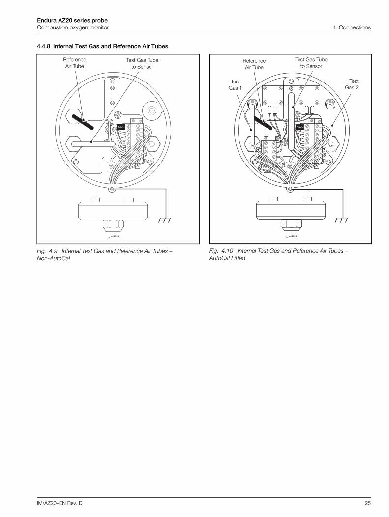
4.4.8 Internal Test Gas and Reference Air Tubes
Fig. 4.9 Internal Test Gas and Reference Air Tubes –Non-AutoCal
�
ReferenceAir Tube
Test Gas Tubeto Sensor
Fig. 4.10 Internal Test Gas and Reference Air Tubes –AutoCal Fitted
�
TestGas 1
ReferenceAir Tube
Test Gas Tubeto Sensor
TestGas 2

Endura AZ20 series probeCombustion oxygen monitor 5 Start-up and Operation
26 IM/AZ20–EN Rev. D
5 Start-up and Operation5.1 Preparation
1. If the probe is not connected permanently to test gaspipework for automatic calibration purposes, ensureblanking plugs are securely fitted to the test gas inletconnections on the probe.
2. If the probe is connected permanently to test gaspipework for automatic calibration purposes, ensure thatthe valve installed in the pipework adjacent to the test gasconnection is closed.
3. Check the connections on both the probe and thetransmitter.
Test gas connections must be checked for leaktight joints.Leaks, especially on permanently pressurizedAutoCal-fitted probes, can cause errors and drain awayexpensive bottles of test gas.
4. Adjust the reference air flow to a stable flow rate between0.3 and 0.5 l / min (0.64 and 1.06 scfh) for probes with norestrictors fitted or 1 bar (15 psi) for probes with restrictorsfitted.
– refer to Section 3.5.2, page 9 for probes fitted withAutoCal.
– refer to Section 3.5.3, page 10 for probes withoutAutoCal.
5. Set the test gas flows – Section 5.2, following.
6. Calibrate the system as detailed in IM/AZ20E-EN
5.2 Setting Up Test GasesThis section prepares the system for manual and automaticcalibration routines by setting up the test gas flows andpressures to suit different AutoCal / restrictor configurations:
refer to Sections 3.5.2 and 3.5.3, pages 9 and 10 for testgas and reference air supply configurations.
connections are the same for remote and integraltransmitters.
5.2.1 AutoCal System with RestrictorsTo set up an AutoCal system with restrictors:
1. Make test gas and reference air connections as detailed inSection 3.5.2, page 9 (remote or integral transmitter).
2. Turn on Test Gas 1 and set the pressure to a nominal1 bar (15 psi).
3. At the transmitter, check the Calibrate / AutoCal Hardware/ Hardware Type parameter is set to Internal.
4. At the transmitter, open the Test Gas 1 valve by selecting:
Calibrate / AutoCal Hardware / Valve Manual Control /Test Gas 1 and pressing to open the valve.
A small icon is displayed to indicate the valve is in theOpen position:
5. Fine tune Test Gas 1 pressure to 1 bar (15 psi).
6. Turn gas off at the transmitter by pressing , then turnTest Gas 1 off at the supply.
7. Repeat steps 2 to 6 for Test Gas 2 (if present).
8. Refer to IM/AZ20E-EN to perform a calibration whenrequired.
Caution. If the test gas connection is not sealedwhen not in use, air leaking into the probe via theconnection causes measurement errors. In apressurized flue, gases venting to atmospherethrough the connection cause corrosion of, and / orblock, the test gas tube. In a negative pressure flue,air leakage causes high O2 reading errors.
Note. Only perform a final system calibration after theprobe has been thermally stable for 2 hours.
Note. The following sections assume the transmitter andprobe are energized, the reference air supply is on and testgases are available.
Valve iconOpen position
Valve iconClosed position

Endura AZ20 series probeCombustion oxygen monitor 5 Start-up and Operation
IM/AZ20–EN Rev. D 27
5.2.2 AutoCal System without RestrictorsTo set up an AutoCal system without restrictors:
1. Make test gas and reference air connections as detailed inSection 3.5.2, page 9 (remote or integral transmitter).
2. Turn on Test Gas 1 and set the pressure to a nominal1 bar (15 psi).
3. At the transmitter, check the Calibrate / AutoCal Hardware/ Hardware Type parameter is Internal.
4. At the transmitter, open the 'Test Gas 1' valve by selecting:
Calibrate / AutoCal Hardware / Valve Manual Control /Test Gas 1 and pressing to open the valve.
A small icon is displayed to indicate the valve is in theOpen position:
5. Fine tune Test Gas 1 pressure to 1 bar (15 psi) and set theflow on the flowmeter to 2.2 l / min (4.662 scfh).
6. Turn gas off at the transmitter by pressing , then turnTest Gas 1 off at the supply.
7. Repeat steps 2 to 6 for Test Gas 2 (if present).
8. Refer to IM/AZ20E-EN to perform a calibration whenrequired.
5.2.3 Non-AutoCal System with RestrictorsTo set up an Non-AutoCal system with restrictors:
1. Make test gas and reference air connections as detailed inSection 3.5.3, page 10 (remote or integral transmitter).
2. Turn on Test Gas 1 and adjust the pressure to1 bar (15 psi).
3. Turn Test Gas 1 off at the supply.
4. Repeat steps 2 to 4 for Test Gas 2 (if present), connect theTest Gas 2 line to the probe’s external TG1 connection.
5. Refer to IM/AZ20E-EN to perform a calibration whenrequired.
5.2.4 Non-AutoCal System without RestrictorsTo set up an Non-AutoCal system without restrictors:
1. Make test gas and reference air connections as detailed inSection 3.5.3, page 10 (remote or integral transmitter).
2. Turn on Test Gas 1, adjust the pressure to 1 bar (15 psi)and the flow on the flowmeter to 2.2 l / min (4.662 scfh).
3. Turn Test Gas 1 off at the supply.
4. Repeat steps 2 to 4 for Test Gas 2 (if present), connectingthe Test Gas 2 line to the probe’s external TG1connection.
5. Refer to IM/AZ20E-EN to perform a calibration whenrequired.
Valve icon'Open' position
Valve icon'Closed' position
Note. Test Gas 1 and 2 connections are made to theprobe’s external Test Gas 1 (TG1) connection andmust be switched manually – see section 3.5.3, page10.
Note. Test Gas 1 and 2 connections are made to theprobe’s external Test Gas 1 (TG1) connection andmust be switched manually – see section 3.5.3, page10.

Endura AZ20 series probeCombustion oxygen monitor 6 Endura AZ20 Probe Specification
28 IM/AZ20–EN Rev. D
6 Endura AZ20 Probe SpecificationPhysicalProbe insertion lengths
Process connection
Probe body material316L stainless steel
Mounting angleHorizontal to vertically down
Process ConditionsStandard process temperature
Process pressureDesigned to withstand 35 kPa (5.1 psi) – positive or negative(pressure compensation required above 5 kPa (0.7 psi) – transmittercan apply fixed pressure compensation
* For > 2 m (6.6 ft.) probes, special conditions may apply
Operating requirementsReference air
Test gasUser-selectable, 100 ... 0.1 % O2 balance N2 and / or air(air is recommended as one of the test gases)
CalibrationManual, semi-automatic or automatic(controlled by Endura AZ20 transmitter)
Automatic calibrationAutoCal hardware
Optional built-in solenoid valves for control of test gas flow
Built-in pressure switches to detect presence of test gases
Heater Operational RequirementsEndura AZ20 Probe Heater
Nominally 190 , 70 W at 115 V AC – power is limited to 70 W max.by Endura AZ20 transmitter over a 100 ... 240 V AC ±10 % (90 V min.264 V max.) 50 / 60 Hz range.
Endura AZ20/ZFG2 Replacement Probe HeaterNominally 25, 120 W at 55 V AC – for use with ZDT or ZMTtransmitters only
DS/AZ20–EN Rev. E
0.5 m (1.7 ft.) 2.5 m (8.2 ft.)
1.0 m (3.3 ft.) 3.0 m (9.9 ft.)
1.5 m (5.0 ft.) 3.5 m (11.5 ft.)
2.0 m (6.6 ft.) 4.0 m (13.1 ft.)
All probe lengths:
ANSI B16.5 150 lb
2, 2.5, 3, 4 in
DIN2501 Part 1
65, 80, 100 mm
JIS B2238 5K
NPT
(flange pressure ratings do not apply)
0.5 m (1.7 ft.) probes ABB 500 mm (19.7 in)standard flange
1.0 m (3.3 ft.) and longer ABB 1000 mm (39.4 in)standard flange
Note. Horizontally-mounted probes greater than 2.0 m (6.6ft.) in length may need to be supported.
All probe lengths* –20 ... 800 °C (–4 ... 1472 °F)
Regulatedsupply
Probes with restrictors 1 bar (15 psi),flowmeters not required
Probes withoutrestrictors
1 bar (15 psi)flowmeters required withflow set to 0.3 ... 0.5 l / min(0.64 ... 1.06 scfh)
Pumpedsupply
Probes with / withoutrestrictors
Preset flow0.3 ... 0.5 l / min(0.64 ... 1.06 scfh)
Probes withrestrictors
1 bar (15 psi) – flowmeters not required asrestrictors preset flow to 2.2 l / min(4.662 scfh)
Probes withoutrestrictors
1 bar (15 psi) flowmeters required,set to 2.2 l / min (4.662 scfh) flow

Endura AZ20 series probeCombustion oxygen monitor Appendix A – Principle of Operation
IM/AZ20P–EN Rev. D 29
Appendix A – Principle of OperationThe Endura AZ20 probe's zirconia cell is a thimble-shaped sensing element fitted with inner and outer electrodes at its closed end.The inner electrode is exposed to the flue gas entering the open end of the cell; the outer electrode is supplied with reference air froma pump or regulator and is therefore exposed to a constant partial pressure of oxygen (20.95 % O2). The cell is held at a constant700°C (1292 °F) by a heater and control thermocouple.
Because zirconia is an electrolyte that conducts only oxygen ions at temperatures in excess of 600°C (1112 °F), the voltagegenerated between the electrodes (the cell output) is a function of the ratio of the oxygen partial pressure difference between thereference electrode and the measuring electrode and its temperature. Therefore, any change in the oxygen partial pressure of the fluegas at the exposed electrode produces a change in the cell output voltage as dictated by the Nernst equation.
Cell output voltage increases logarithmically with decreasing oxygen, thus providing high sensitivity at low oxygen levels.
Fig. A.1 Endura AZ20 Probe Construction
High Temperature Seal
FlueGas
Insulator Heater Element (700°C [1292 °F])
Reference Air
Diffuser / Flame Arrester Test Gas Control Thermocouple 'K'
Cell Output– Ve + Ve
Cell

Endura AZ20 series probeCombustion oxygen monitor Appendix B – Endura AZ20/ZFG2 Replacement Probe
30 IM/AZ20P–EN Rev. D
Appendix B – Endura AZ20/ZFG2 Replacement ProbeThe Endura AZ20/ZFG2 replacement probe can be connected to existing ZMT transmitters or ZDT-FG analyzers to replace exisingZFG2 probes. To allow direct replacement, Endura AZ20/ZFG2 replacement probes are supplied with a single M20 gland conduit of 6or 10 m (18 or 30 ft) length. NPT versions are supplied with a single 1/2 in NPT female threaded entry only.
Note. For Endura AZ20/ZFG2 replacement probe test gas and connection details at the existing ZMT transmitter or ZDT-FGanalyzer, refer to the following manuals:
IM/ZDT-FG – copies of the IM/ZDT/FG manual can be downloaded from the ABB web site (www.abb.com).
IM/ZMT – copies of the IM/ZMT manual can be downloaded from the ABB website (www.abb.com).
Fig. B.1 Endura AZ20/ZFG2 Replacement Probe with Existing System
��������
������
��������� ����� �!
�������
����
������
Measured gaspressure limits
– must beconstant
±0.35 bar (5 psi)
20 mm or1/2 NPT Gland
External Reference Air Supply Line Required for ZMTTransmitter or ZDT-FG Analyzer Without Internal Pump
Vent to Dry Area(Unrestricted Flow)
Flue
ABB Reference Air Unit – Existing Installationor ABB Reference Air Pump – see AppendixD, page 36
TG 1
Vent
External ReferenceAir Connection
Existing ZMT Transmitter orZDT-FG Analyzer– see Note below
Endura AZ20/ZFG2Replacement ProbeNo AutoCal**
Endura AZ20/ZFG2 Replacement Probe Issupplied with probe conduit(6 or 10 m [18 or 30 ft])
Conduit connections should be made at ZMT/ZDTEnd (No conduit on NPT version)
*Test Gas
Internal Reference Air Connection – see Appendix B.2, page 33
External Reference AirSupply from
Transmitter / Analyzer
Conduit Including Internal Reference AirLine From Transmitter / Analyzer with
Reference Air Supply
Ref. Air
0.5 to 2 m(1.7 to 6.6 ft.)
600 °C (1112 °F)70 °C(158 °F)
–20 °C(–4 °F)
–20 °C(–4 °F)
*Optional solenoid valve where the line length between gas panel and probe head > 10 m (32.8 ft.).
**See Probe Specification, page 28 for heater operational requirements.

Endura AZ20 series probeCombustion oxygen monitor Appendix B – Endura AZ20/ZFG2 Replacement Probe
IM/AZ20P–EN Rev. D 31
B.1 Endura AZ20/ZFG2 Replacement Probe Conduit Electrical Connections
B.1.1 Electrical ConnectionsReferring to Fig. B.2:
1. Unscrew and remove probe end capA.
2. Pass conduit B through probe entry gland C takingcare not to disturb the probe’s internal wiringD.
3. Tighten cable glandC.
4. Make connections E to colored terminal plugconnections as shown in Table B.1:
5. Make reference air connections as detailed in AppendixB.1.2, page 32.
Important.
For removal of the existing ZFG2 probe (complete withits conduit assembly) and installation of the EnduraAZ20/ZFG2 replacement probe, refer to the ZFG2probe manual (this manual can be downloaded fromthe ABB web site at (www.abb.com) or by clicking thefollowing link: IM/ZFG2).
The Endura AZ20/ZFG2 replacement probe must beinstalled using the new conduit supplied with theprobe.
Terminal / CableColor
Tag ID Connection
VioletNot Used
Grey
Red Cell + Oxygen Input (+ve)
Blue Cell – Oxygen Input (–ve)
White TC+ Thermocouple (+ve)
Blue TC – Thermocouple (–ve)
Braid Cell SCN Screen
Brown H Heater
Blue H Heater
Table B.1 Probe Transmitter Cable Connections
Fig. B.2 Endura AZ20/ZFG2 Replacement Probe –Conduit Electrical Connections
�
�
�
�
Colored TerminalPlug connections

Endura AZ20 series probeCombustion oxygen monitor Appendix B – Endura AZ20/ZFG2 Replacement Probe
32 IM/AZ20P–EN Rev. D
B.1.2 Endura AZ20/ZFG2 Replacement Probe –Conduit Reference Air ConnectionsReferring to Fig. B.3:
1. For probes using the conduit (internal) Reference Air line:
a. disconnect pipeA at the hexagonal fittingB.
b. reconnect pipeA to the internal Reference Air tubeC coming from the conduit – ensure flexible tubingdoes not kink (especially after the probe end cap isre-fitted)
c. fit a blanking plug to the external 'Ref. Air'connection at B on the probe body to preventwater ingress
d. proceed to step 3.
2. For probes using an external Reference Air line, connectthe existing reference air supply line to the probe’s external'Ref. Air' connection – see section 4.4.6, page 24.
3. Refit probe end capD and screw it hand-tight.
4. Refer to Appendix B.2, page 33 for connections toZDT-FG analyzers or Appendix B.3 page 34 forconnections to ZMT transmitters.
Fig. B.3 Endura AZ20/ZFG2 Replacement Probe –Conduit Reference Air Connections
��
�

Endura AZ20 series probeCombustion oxygen monitor Appendix B – Endura AZ20/ZFG2 Replacement Probe
IM/AZ20P–EN Rev. D 33
B.2 ZDT-FG Analyzer Connections
B.2.1 Disconnecting the Existing ZFG2 ProbeReferring to Fig. B.4:
1. Unlock and remove the lower panel A from the ZDT-FGanalyzer, remove the 2 shroud retaining screws B andremove shroudC.
2. Disconnect wires from heater terminal D, cell terminalE, thermocouple terminal F and loosen conduit entryglandG.
3. For analyzers using the conduit’s Reference Air line,disconnect existing reference air supply H, remove theconduit and proceed to step 5.
4. For analyzers using an external Reference Air connection,leave the existing reference air supply pipeI in place.
B.2.2 Connecting the Endura AZ20/ZFG2 ReplacementProbeReferring to Fig. B.4:
1. Pass the new conduit through entry glandG and tightenthe gland.
2. Make connections to heater terminalD, cell terminalE,thermocouple terminalF as shown in Table B.2.
3. For probes using the conduit’s Reference Air supply,connect conduit reference air lineH.
4. Refit shroud C and secure it with the 2 shroud retainingscrewsB.
5. Refit the lower panelA.
Warning. Before disconnecting existing ZFG2 conduit, orconnecting the new Endura AZ20/ZFG2 replacement probeconduit, ensure the power supply, any powered controlcircuits and high common-mode voltages are switched off.
Note. For analyzers without internal pumps, the ReferenceAir connection is made directly to the probe’s external 'Ref.Air' connection – see Fig. B.1, page 30.
ZDT-FGTerminal
Connection Wire
H Heater Brown
H Heater Blue
E Heater EarthGreen /Yellow
Cell + Oxygen Input (+ve) Red
Cell – Oxygen Input (–ve) Blue
Cell SCN Oxygen Input Screen Braid
TC+ Thermocouple (+ve) White
TC– Thermocouple (–ve) Blue
Table B.2 Conduit Connections at ZDT-FG Analyzer
Fig. B.4 Endura AZ20/ZFG2 Replacement ProbeConduit Connections at ZDT-FG Analyzer
" " � # � ��� # �
� � �
� � �
�
*External air line to internal pump (used if conduit air line is notconnected). For analyzers with no internal pump, the Referenceair line connects directly to the probe’s external 'Ref. Air'connection – see Fig. B.1, page 30.
Inte
rnal
Ext
erna
l*

Endura AZ20 series probeCombustion oxygen monitor Appendix B – Endura AZ20/ZFG2 Replacement Probe
34 IM/AZ20P–EN Rev. D
B.3 ZMT Transmitter Connections
B.3.1 Disconnecting the Existing ZFG2 ProbeReferring to Fig. B.3:
1. Unlock and open the door A, remove the 2 retainingscrewsB and remove the mains protection plateC.
2. Disconnect wires from heater terminal D, cell terminalE and thermocouple terminal F and loosen conduitentry glandG.
3. For probes using the conduit’s Reference Air line,disconnect existing reference air supply pipe H, removethe conduit and proceed to step 5.
4. For probes using an external Reference Air connection,leave the existing reference air supplyI in place.
B.3.2 Connecting the Endura AZ20/ZFG2 ReplacementProbeReferring to Fig. B.3:
1. Pass the new conduit through entry glandG and tightenthe gland.
2. Make connections to heater terminal D, cell terminal Eand thermocouple terminalF, as listed in Table B.2.
3. For probes using the conduit’s Reference Air supply,connect conduit reference air lineH.
4. Refit the mains protection plate C and secure it with the2 retaining screwsB.
5. Close and lock the doorA.
Warning. Before disconnecting or connecting conduit,ensure the power supply, any powered control circuits andhigh common-mode voltages are switched off.
Note. For transmitters without internal pumps, theReference Air connection is made directly to the probe’sexternal 'Ref. Air' connection – see Fig. B.1, page 30.
ZMT Terminal Connection Wire
H Heater Brown
H Heater Blue
E Heater EarthGreen /Yellow
Cell + Oxygen Input (+ve) Red
Cell – Oxygen Input (–ve) Blue
Cell SCN Oxygen Input Screen Braid
TC+ Thermocouple (+ve) White
TC– Thermocouple (–ve) Blue
Table B.3 Conduit Connections at ZMT Transmitter
Fig. B.5 Endura AZ20/ZFG2 Replacement ProbeConduit Connections at ZMT Transmitter
���
�
� �
�

Endura AZ20 series probeCombustion oxygen monitor Appendix C – Using an External Automatic Calibration Panel
IM/AZ20P–EN Rev. D 35
Appendix C – Using an External Automatic Calibration Panel
Referring to Fig. C.1, relay outputs 1 and 2 from the Endura AZ20 transmitter can be used to switch solenoid valves in an externalautomatic calibration panel to provide AutoCal functionality. The external automatic calibration components must be powered by anindependent supply.
Warning. Isolate the Endura AZ20 transmitter and external automatic calibration panel before making AutoCal connections.
Fig. C.1 Schematic – Example of External Automatic Calibration Panel
Relay 1 and 2 Outputs– see IM/AZ20E–EN for Connections
ReferenceAir
Test Gas 1
Test Gas 2
ProbeTest GasConnections
*SolenoidValve 1
*SolenoidValve 2
ReferenceAir
TestGas
External Automatic Calibration Panel
Test gas pressure 1 bar (15 psi)= 2.2 L / min (4.662 scfh)
Endura AZ20 Transmitter Relay Outputs
Refer to Section 3.4, page 7 for test gasand reference air pressures
*24 V, 2 W or relay NO / NC

Endura AZ20 series probeCombustion oxygen monitor Appendix D – Accessories and Spares
36 IM/AZ20P–EN Rev. D
Appendix D – Accessories and SparesD.1 Documentation
D.2 Probe Spares
Part No. Description
IM/AZ20M–EN Maintenance Guide
Download* the MaintenanceGuide from:
www.ABB.com/analytical-instruments
*Enter this address in your browser and then typeIM/AZ20M-EN in the search box. The Maintenance Guideis the top link.
Part No. Description
AZ200 700 Cell Assembly(includesCommissioning labeland C-ring)
AZ200 727 RestrictorUpgrade Kit
AZ200 728 Probe End Cap (includes wiring labels)
AZ200 729 Diffuser Flame Arrestor Assembly(includes C-ring)
AZ200 730 (NPT)AZ200 733 (BSP)
AutoCal Upgrade Assembly
Lengthdependant:AZ20 Standard –see Table D.2
AZ20/ZFG2ReplacementProbe – see TableD.3
AZ20 Standard Heater AssemblyAZ20/ZFG2 Replacement Heater Assembly
Applicationdependant– see Table D.4
ABB Flowmeter
Length dependant– see Table D.1
Thermocouple / Electrode Assembly
���������������������
���������������
!��"�#���$��%�"&'(����)*+�#�,�-+#�.�""�/���/)�"0�
1# 2221# 222
��%����)3.�""�/
����)*+�#�
����)3.�""�/�"��4�%�*����"��4�%�*���
���������� �����������������������������������������������
*+�#�3.�""�/*+�#�3�"&'(
*+�#�35�&)-�*+�#�3����)
*+�#�3��%*+�#�3�"0�
*+�#�3.�""�/*+�#�3�"&'(*+�#�35�&)-�*+�#�3����)*+�#�3��%*+�#�3�"0�
�0#��&"�56#��)�7�����##�%8
�� ���� �� ���� ��� !"��# !"� ���$ !"�
% & ' & ( ����)* �����$ +� �)# +� �� ! ,� -� -
��������
2 � � � �
��������������������
��������
��%�"0�*+�#��"0��'���)3�&�#+���/)�"0�
��%����)3.�""�/
����)*+�#�
����)3.�""�/�"��4�%�*����"��4�%�*���
%'(*$# ��
.���/���
.���/��� ����) �����+� �)+� ��! ,�0
--
99��)#��""�%���&#���!�"#&-����!�����&:�
��)
%0�#
9���������,�)�
����������������� �!���"���"#�����$�� �����������
�'���)
9���������,�)����;���)%0�#
��""��&<"�
���&<"�
99��&#����&<"�
AZ20Version
AZ20/ZFG2Replacement Version
AZ200 731AZ200 732
Oil-coalescingFilter-Regulator:1/4 NPT 5 µm1/4 BSP 5 µm
AZ200 740AZ200 741
AZ200 742AZ200 743
Filter elements for pre-June 2013 regulator:5µm filter elementOil coalescing filter element
Filter elements for post-June 2013 regulator:5µm filter cartridgeOil coalescing filter cartridge
AZ200 770AZ200 771AZ200 772AZ200 773
ABB Reference Air Pump:1/4 BSP (Metric) 230 V AC 50 / 60 Hz1/4 BSP (Metric) 115 V AC 50 / 60 Hz1/4 NPT (Imperial) 230 V AC 50 / 60 Hz1/4 NPT (Imperial) 115 V AC 50 / 60 Hz
Probe Length Part Number Probe Length Part Number
0.5 m (1.7 ft.)1.0 m (3.3 ft.)1.5 m (5.0 ft.)2.0 m (6.6 ft.)
AZ200 701AZ200 702AZ200 703AZ200 704
2.5 m (8.2 ft.)3.0 m (9.9 ft.)3.5 m (11.5 ft.)4.0 m (13.1 ft.)
AZ200 705AZ200 706AZ200 707AZ200 708
Table D.1 Thermocouple / Electrode Assembly
Probe Length Part Number Probe Length Part Number
0.5 m (1.7 ft.)1.0 m (3.3 ft.)1.5 m (5.0 ft.)2.0 m (6.6 ft.)
AZ200 710AZ200 711AZ200 712AZ200 713
2.5 m (8.2 ft.)3.0 m (9.9 ft.)3.5 m (11.5 ft.)4.0 m (13.1 ft.)
AZ200 714AZ200 715AZ200 716AZ200 717
Table D.2 AZ20 Standard Probe Heater Assembly
Probe Length Part Number
0.5 m (1.7 ft.)1.0 m (3.3 ft.)1.5 m (5.0 ft.)2.0 m (6.6 ft.)
AZ200 720AZ200 721AZ200 722AZ200 723
Table D.3 AZ20/ZFG2 Replacement Probe Heater Assembly
Flowmeter Type PartNumber
1/4 NPT Flowmeter (Reference Air): 0.1 to 0.85 l / min(0.21 to 1.8 scfh) STP1/4 BSP Flowmeter (Reference Air): 0.1 to 0.85 l / min(0.21 to 1.8 scfh) STP1/4 NPT Flowmeter (Test Gas): 0.6 to 4.4 l / min(1.27 to 9.32 scfh) STP1/4 BSP Flowmeter (Test Gas): 0.6 to 4.4 l / min(1.27 to 9.32 scfh) STP
AZ200 786
AZ200 787
AZ200 788
AZ200 789
Table D.4 ABB NPT/BSP Flowmeters
Part No. Description
Pre-June 2013regulator
Post-June 2013regulator

Products and customer supportAutomation SystemsFor the following industries:— Chemical & Pharmaceutical— Food & Beverage— Manufacturing— Metals and Minerals— Oil, Gas & Petrochemical— Pulp and Paper
Drives and Motors— AC and DC Drives, AC and DC Machines, AC Motors to
1kV— Drive Systems— Force Measurement— Servo Drives
Controllers & Recorders— Single and Multi-loop Controllers— Circular Chart and Strip Chart Recorders— Paperless Recorders— Process Indicators
Flexible Automation— Industrial Robots and Robot Systems
Flow Measurement— Electromagnetic Flowmeters— Mass Flowmeters— Turbine Flowmeters— Wedge Flow Elements
Marine Systems & Turbochargers— Electrical Systems— Marine Equipment— Offshore Retrofit and Refurbishment
Process Analytics— Process Gas Analysis— Systems Integration
Transmitters— Pressure— Temperature— Level— Interface Modules
Valves, Actuators and Positioners— Control Valves— Actuators— Positioners
Water, Gas & Industrial Analytics Instrumentation— pH, Conductivity and Dissolved Oxygen Transmitters and
Sensors— Ammonia, Nitrate, Phosphate, Silica, Sodium, Chloride,
Fluoride, Dissolved Oxygen and Hydrazine Analyzers— Zirconia Oxygen Analyzers, Katharometers, Hydrogen
Purity and Purge-gas Monitors, Thermal Conductivity
Customer supportWe provide a comprehensive after sales service via aWorldwide Service Organization. Contact one of the followingoffices for details on your nearest Service and Repair Centre.
UKABB LimitedTel: +44 (0)1453 826661Fax: +44 (0)1453 829671
USAABB Inc.Tel: +1 215 674 6000Fax: +1 215 674 7183
Client WarrantyPrior to installation, the equipment referred to in thismanual must be stored in a clean, dry environment, inaccordance with the Company's published specification.Periodic checks must be made on the equipment'scondition. In the event of a failure under warranty, thefollowing documentation must be provided assubstantiation:— A listing evidencing process operation and alarm logs
at time of failure.— Copies of all storage, installation, operating and
maintenance records relating to the alleged faulty unit.

Contact us
IM/A
Z20P
–EN
06.1
3ABB LimitedProcess AutomationOldends LaneStonehouseGloucestershire GL10 3TAUKTel: +44 1453 826 661Fax: +44 1453 829 671
ABB Inc.Process Automation125 E. County Line RoadWarminsterPA 18974USATel: +1 215 674 6000Fax: +1 215 674 7183
www.abb.com
NoteWe reserve the right to make technical changes ormodify the contents of this document without priornotice. With regard to purchase orders, the agreedparticulars shall prevail. ABB does not accept anyresponsibility whatsoever for potential errors orpossible lack of information in this document.
We reserve all rights in this document and in thesubject matter and illustrations contained therein.Any reproduction, disclosure to third parties orutilization of its contents in whole or in parts – isforbidden without prior written consent of ABB.
Copyright© 2013 ABBAll rights reserved