enerboss 400c series vertical fan coil - clear...
TRANSCRIPT
July 5/2011
Enerboss 400C Series Vertical Fan Coil
Specifications, Installation, Operation and Maintenance Manual

July 5/2011
1 INSTALLATION .................................................................................... 3
Locating the Fan Coil ......................................................................................... 3 1.1
Framing ............................................................................................................... 3 1.2
Electrical Power Connection ............................................................................. 3 1.3
Control and Electrical Connections.................................................................. 4 1.4
Plumbing ............................................................................................................. 4 1.5
Ducting ................................................................................................................ 4 1.6
2 COMMISSIONING ................................................................................ 5 Supply Air Balancing ......................................................................................... 5 2.1
HRV Balancing ................................................................................................... 5 2.2
Water Side Commissioning ............................................................................... 8 2.3
3 OPERATING THE FAN COIL AND HRV/ERV ................................. 8
General Description ........................................................................................... 8 3.1
Thermostat .......................................................................................................... 9 3.2
Dehumidistat Control (Optional) ...................................................................... 9 3.3
24V Push Button Timers (Optional) ............................................................... 10 3.4
Recommended Seasonal Settings .................................................................... 11 3.5
4 MAINTENANCE .................................................................................. 12
Maintaining Return Filters and HRV/ERV Core ......................................... 12 4.1
5 WARRANTY .......................................................................................... 13
6 TECHNICAL INFORMATION ........................................................... 14 6.1 Nomenclature ..................................................................................................... 14
6.2 Coil Data ............................................................................................................ 15 6.3 4-pipe Heating coil data ..................................................................................... 16 6.4 Fan Curves.......................................................................................................... 17
6.5 Outside Air at Low Speed .................................................................................. 18
6.6 Exhaust Air ......................................................................................................... 18 6.7 HRV Efficiency .................................................................................................. 19 6.8 Sound Level Summary ....................................................................................... 19
6.9 Shop Drawings ................................................................................................... 19 6.10 Electrical ......................................................................................................... 25
6.11 Operational States ........................................................................................... 28

Page 3 of 29
1 INSTALLATION
Locating the Fan Coil 1.1
Clean the floor of debris where the fan coil is to be placed. With the fan coil tipped at the
top, feed the risers down to the unit below through the sleeves provided. Solder the
mating risers and insulate the remaining copper on the supply and return water risers.
Shim the fan coil plumb and level if necessary.
Framing 1.2
Using nominal 2” studs, frame around the fan coil rough-in flange on the left, right, top
and bottom as shown below.
Electrical Power Connection 1.3
Supply the fan coil with 120VAC terminating at the junction box provided inside the
unit. The table below outlines the breaker sizes needed.

Page 4 of 29
ELECTRICAL SPECIFICATIONS
Electrical Volts Watts MCA
No Electric Back up 120/1 400 15
1.5 kW Back up 120/1 1900 20
CONTROLS
POWER CONDUCTOR WIRES
THERMOSTAT 24 VAC 4 18 GA
DEHUMIDISTAT 24 VAC 2 18 GA
TIMERS 24 VAC 2 18 GA
TIMERS 24 VAC 3 18 GA
SPRING WOUND MECHANICAL COUNT DOWN
20-80% MAKE ON RISE
DESCRIPTION
HEAT COOL WITH FAN SWITCH
MOMENTARY PUSH BUTTON WIN20
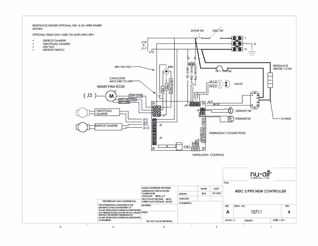
Control and Electrical Connections 1.4
Control wiring is 24 VAC. All controls terminate at a terminal strip inside the fan coil.
Thermostat connections (R,G,Y,W,C), High Ventilation Switch (Hum , 24V) and Dryer
interlock (Dryer SW), Push Button timers (24 V, Timer Sw, indicator).
Plumbing 1.5
The coils come c/w drain and air bleed plugs on the headers. When charging the coils,
open the air bleed plug (top, return header) and manually open the control valve.
Ducting 1.6
Supply Air 1.6.1
Supply air options are: 1) Front, non-ducted. 2) Rear ducted 6x8 or rear ducted 14x8. 3)
Top ducted, 8” dia.
Return Air 1.6.2
Return air options are front, back, left or right and are not typically ducted. A key
operated volume control return air damper supplied with the fan coil is necessary for
proper HRV balancing.
HRV Return Air (Exhaust Air from Building) 1.6.3
At the top, front, left of the fan coil a 5” diameter collar is provided. The HRV return air
collar can be specified when ordering to be top or side and can be changed in the field by
swapping the cover plate and collar plate.
HRV Exhaust Air (Exhaust Air to Outside) 1.6.4
At the top, rear, right of the fan coil a 5” diameter collar is provided. The exhaust air
collar can be specified when ordering to be top or side and can be changed in the field by
swapping the cover plate and collar plate.

Page 5 of 29
HRV Outside Air (Fresh Air from Outside) 1.6.5
At the top, right, front of the fan coil a 5” diameter collar is provided. The outside air
collar can be specified when ordering to be top or side and can be changed in the field by
swapping the cover plate and collar plate.
2 COMMISSIONING
Supply Air Balancing 2.1
The supply air motor is an ECM operating in constant cfm mode. Adding static will not
significantly reduce the total air flow as you would expect with a psc motor. On ducted
systems the amount of air at each grille can be regulated with dampers.
HRV Balancing 2.2
The HRV exhaust air can be adjusted in low and high speed using the control board and
the procedure that follows. The amount of outside air is adjusted using dampers. The
damper in the return air grille can be closed (partially) to increase outside air flow or
opened to decrease outside air flow. If outside air needs to be further reduced, a sliding
damper located in the HRV outside air compartment should be used.
When balancing the HRV:
-Close all windows, doors and
fireplace dampers.
-Turn off any exhaust systems
such as bathroom fans, range
hoods, central vacuums or
dryers.
There are three modes of
operation in which the HRV
needs to be balanced.
1) High speed (High ventilation
switch).
2) Low speed (thermostat fan
ON, no heat or cool calls).
3) Low ventilation with a call for heat or cooling.
Balancing Sequence:
High Speed Balancing – set supply and exhaust to the specified flows
Low speed balancing – Fan On. Reduce the higher flow to match the lower
Low speed with heat/cool call on – using the throttling damper, match the outside air
flow to that of the exhaust air.
Exhaust air
measuring
port
Fresh Air
measuring
port

Page 6 of 29
B
Balancing mode 1 2.1.1
High Speed Balancing:
With all dampers fully open and the exhaust fan speeds at
the factory setting, run the fan coil in high ventilation
mode. Using a hot wire anemometer or pitot tube and
micromanometer measure the air velocity (hot wire) or
velocity pressure (micromanometer) in the HRV return
and HRV outside air. The table below shows cfm values
for various meter readings.
2.3.1.1 Outside Air High Speed Adjustment
If the outside air flow is too low, gradually close
the return air grille damper (A) until the desired
OA flow is measured. If the outside air flow is too
high gradually close the outside air balancing
damper (B) until the OA flow is obtained.
Outside Air Return Air
Flow Velocity Pressure Velocity Pressure
CFM fpm inwc fpm inwc
30 238 0.0035 221 0.0030
40 317 0.0063 294 0.0054
50 397 0.0098 368 0.0084
60 476 0.0142 441 0.0122
70 556 0.0193 515 0.0166
80 635 0.0252 588 0.0216
90 714 0.0319 662 0.0274
100 794 0.0394 735 0.0338
110 873 0.0476 809 0.0409
120 952 0.0567 882 0.0487
Balancing
Ports

Page 7 of 29
2.3.1.2 Exhaust Air High Speed Adjustment
From the window in the HRV access door (C), locate the two blue
pots on the circuit board. The top pot adjusts the exhaust fan HIGH
speed. Turn clockwise to increase and counterclockwise to decrease
CFM. Adjust the exhaust flow rate to within 10% of the OA rate (step
2.2.1)
Balancing Mode 2 2.3.2
2.3.2.1 Low Speed Balancing
Measure and record the flow rate of the Outside Air with the fan coil
in low speed ventilation (fan On, thermostat system switch off) using
the same method described above. Note: No adjustment can be made
to this flow without affecting the high speed flow and repeating the
high speed balance.
Measure the exhaust air from building low speed flow.
Use the lower pot to adjust the exhaust fan LOW speed.
Turn clockwise to increase and counterclockwise to decrease CFM
Adjust until the flow matches that of the outside air.
Balancing Mode 3 2.3.3
2.3.3.1 Low Ventilation on a Call for
Heat
On a call for heat or cool the main fan motor
increases speed. To prevent over ventilating
during the call, a throttling damper (D) partially
closes the outside air opening. Several damper
stop points (E) are available on the throttling
damper assembly. 1) Measure the outside air
when the fan coil is in a call for heat and set the
stop to a more open position if more OA is
need for balance or a more closed position is
less OA is needed. 2) Adjust the OA flow
within 10% of the EA flow in low speed. The
exhaust air flow rate in a call for heat or
cooling should not change from that of low
ventilation mode.
A
C
D
E

Page 8 of 29
Water Side Commissioning 2.3
The coil(s) must be fully charged and free of air. To determine the water flow through
the coil and the output of the unit measure the entering and leaving water temperatures
and the entering and leaving air temperatures with the fan coil in a call for heat ( or
cooling as appropriate). The water flow rate and unit output can be calculated with the
equations given.
C409 gpm = 0.7*{temperature change air (F)}/{temperature change water (F)}
C412 gpm = 0.9*{temperature change air (F)}/{temperature change water (F)}
C418 gpm = 1.0*{temperature change air (F)}/{temperature change water (F)}
C430 gpm = 1.8*{temperature change air (F)}/{temperature change water (F)}
C409 Btu/hr = temperature change air (F) *350
C412 Btu/hr = temperature change air (F) *450
C418 Btu/hr = temperature change air (F) *500
C430 Btu/hr = temperature change air (F) *900
3 OPERATING THE FAN COIL AND HRV/ERV
General Description 3.1
The Enerboss Integrated Fan Coil has two fans:
The main fan circulates air in the space and also brings in fresh air from outdoors. A
smaller fan serves to exhaust air from the space (HRV exhaust).
Understanding Your Heat/Energy Recovery Ventilator (HRV/ERV)
The heat (energy) exchange system in the Enerboss provides ventilation air at a
prescribed rate to maintain a healthy, comfortable indoor environment while reclaiming
energy from the exhausted stale air.
3.1.1 How It Works
The HRV exhausts air from rooms in the home that produce the most odors, humidity,
VOC’s and other pollutants. This air is exhausted to the outdoors through a heat/energy
recovery core. At the same time, fresh air from outdoors is drawn into the HRV core
where the energy from the outgoing stale air is transferred to the incoming fresh air. The
conditioned fresh air is then blended with the circulating air of the heating/cooling system
and distributed to the living areas of the home through the supply ductwork (or direct
supply grills).
The Enerboss integrated HRV/ERV is a 2-speed system:

Page 9 of 29
When the thermostat switch is in Fan ON mode the HRV/ERV runs continuously on low
speed, increasing to high speed on call from a timer or optional dehumidistat.
When the thermostat switch is in Fan AUTO mode the HRV/ERV is in standby and will
provide low volume ventilation only on a call for heat, or will provide high speed
ventilation on call from an optional dehumidistat or timer .
Thermostat 3.2
The thermostat should have as a minimum two switches:
A “system switch” controls the mode of operation (heat, cool or off), and a “fan switch”
controls fan operation (On or Auto).
System Switch 3.2.1
System OFF: System does not react to heating or cooling.
System COOL: System is in cooling mode, fan coil comes on when room temperature
rises above set point.
System HEAT: System is in heatign mode, fan coil comes on when room temperature
drops below set point.
Fan Switch 3.2.2
FAN AUTO (intermittent operation): The Enerboss will operate with a call for heating or
cooling or high ventilation from one of the remote controls. Fan operation will cease and
the unit will turn off once the call is satisfied. Low ventilation only occurs on a call for
heat or cool.
FAN ON (continuous): The Enerboss will constantly circulate air on low speed and
ventilate continuously in low volume. On a call for Heating or Cooling unit will go into
high speed cooling/heating and resume low speed after the thermostat is satisfied. On
call from a remote control the unit will go into high speed ventilation and resume low
speed after the remote is satisfied. This is the recommended setting for occupied spaces.
Dehumidistat Control (Optional) 3.3
Excessive ambient humidity can be controlled with an optional wall mounted
dehumidistat. The dehumidistat will initiate high speed ventilation when the humidity
sensor detects humidity in the air around it to be higher than the dehumidistat set point.
In hi-speed ventilation the small exhaust fan will run at high speed and the main fan will
operate at high speed. The Enerboss will cease high speed ventilation when the humidity
sensor detects lower humidity than set point.
Note: Dehumidistat settings do not need to be changed frequently; usually once
when the weather starts to get hot and humid (late spring, early summer), and again
when the weather starts to get cool and dry (late fall, early winter).
Page 10 of 29
Typical seasonal settings for the dehumidistat dial are as follows:
Summer: 80% or OFF
Winter: 40-60%
Dehumidistat Wiring:
Use 2-Conductor low voltage wire. Connect to 24 VAC and Humidity
Dehumidistat Settings and Responses 3.2.3
When Thermostat Fan Switch is ON
If indoor humidity is below dehumidistat set point the HRV runs in low speed. The HRV
fan and the main fan will operate in low.
If the indoor humidity rises above the dehumidistat set point the HRV runs in high speed.
The HRV fan and the main blower will operate in high until switch is disengaged.
When Thermostat Fan Setting - AUTO
If the indoor humidity is below the dehumidistat set point the main fan and HRV will be
off.
If the indoor humidity is above the dehumidistat set point the HRV runs in high speed.
The HRV fan and the main blower will operate in high speed.
24V Push Button Timers (Optional) 3.4
Twenty minute timers (Part # WIN-20) may be located in bathrooms, kitchen or laundry
room for timed source control of humidity and odor. Engaging the timer sends the
ventilation system to high speed for twenty minutes to evacuate odor, excess humidity or
other indoor pollutants. Longer timed cycles can be obtained with mechanical timers.
Wiring
20 minute timers connect to: 24 VAC; Timer Switch and LED Indicator.
Mechanical timers connect to: 24 VAC and Humidity.
Timer Settings and Responses 3.2.4
Thermostat Fan Setting - ON
The HRV fan and the main fan will operate in low. When the timer is ON the fan coil
will be in high ventilation mode. The HRV fan and the main blower will operate in high
until the switch is disengaged.
Thermostat Fan Setting - AUTO

Page 11 of 29
The HRV will be off. Both fans will be off except on call for heat or cooling. When the
timer is turned ON the fan coil will be in high ventilation mode. The HRV fan and the
main blower will operate in high until the switch is disengaged.
Recommended Seasonal Settings 3.5
Hot, Humid Seasons: 3.2.5
Dehumidistat: 80% or OFF
Thermostat: COOL, Fan Switch ON (continuous)
High speed ventilation will rarely (dehumidistat at 80%) or never (dehumidistat at OFF)
take place. The main blower will usually operate in low speed, circulating cool air
throughout the home and introducing low levels of fresh air and expelling exhaust air
through the ventilation system. The main blower will go into high speed with a call from
the thermostat for cooling. Continuous ventilation is recommended for optimal air
quality.
Additional adjustment: If high ventilation takes place too often, switch dehumidistat to
OFF.
Cool, Cold Seasons: 3.2.6
Dehumidistat: 40-60%
Thermostat: HEAT, Fan Switch ON (continuous)
High speed ventilation will take place when the dehumidistat set point is exceeded. After
the dehumidistat is satisfied, the main blower will return to low, circulating warm air
throughout the home, while exchanging a small amount of fresh air and exhausting an
equal amount of stale air through the ventilation system. The main blower will go into
high speed with a call from the thermostat for heating, but ventilation rates will remain
low. Continuous ventilation is recommended for optimal air quality.
Adjusting the Dehumidistat setting: If high speed ventilation takes place too often, raise
the humidity setting on your dehumidistat in 5% steps. If condensation forms on the
windows, the dehumidistat setting should be lowered. The dehumidistat should always
be set higher (15%) than a humidifier if one is installed.
NOTES:
Continuous operation (Fan ON) is recommended when the suite is occupied.
Constant air circulation results in even temperature throughout the suite, from floor to
ceiling, from room to room.
Improved indoor air quality (IAQ): Constant circulation means constant ventilation.
The ECM motor in the unit uses less than 30 watts in circulation mode and is ~ 74%
more efficient than the commonly used PSC motor.

Page 12 of 29
4 MAINTENANCE
Maintaining Return Filters and HRV/ERV Core 4.1
Regular maintenance of your filters and core will
ensure their effective operation and longevity.
The Return Air Filter 4.1.1
The return air filter (located against the coil in the
lower section of the fan coil) is a disposable filter that
should be checked every three months and replaced
as needed (typically 6 or 12 months). This filter can
be replaced with any standard 10x20x1” filter of the
same efficiency (MERV 4-6). To access the return air
filter:
1) Remove the outer finish panel by pulling toward
you from the bottom.
2) Remove the lower cover by lifting and tilting the
top outward.
3) Place the new filter in the filter brackets on the coil
plate with the wire mesh toward the coil.
The HRV/ERV Filters 4.1.2
Remove the finished panels (bottom and top) and
inner covers (2).
Slide the HRV filters along their guides toward you
and remove.
Vacuum the HRV filters and replace them (as
needed).
Repeat every 90 days.
The HRV Core (polypropylene media) 4.1.3
Remove the finish and access panels as described previously
Slide the HRV core toward you along its guides.
Vacuum or wash the core. If washing the core, let dry before replacing.
Repeat every 6 to 12 months.
The ERV Core (polymer media) 4.1.4
Remove the energy exchange core as you would an HRV core.
Nu-Air polymer cores can be washed or vacuumed
Repeat every 6 to 12 months.
RA Filter
Rack
HRV
Filters (2)
Core
Page 13 of 29
5 WARRANTY
YOUR ENERBOSS
TRANSFERABLE WARRANTY
Should your Enerboss cease to function within two (2) years of the date of original
purchase due to defective material of workmanship of the product, NU-AIR Ventilation
Systems Inc. will supply a new or rebuilt part FOB factory to replace the defective part.
Delivery, installation, and labor cost would be your responsibility.
Lifetime Core Warranty
If the core in your NU-AIR Heat Recovery Ventilator fails due to a defect in material or
workmanship NU-AIR Ventilation Systems Inc. will supply a new core FOB factory to
replace the defective part. Delivery and labor costs are your responsibility. Should an
ERV core cease to function within five (5) years of the date of original purchase due to
defective material of workmanship of the product, NU-AIR Ventilation Systems Inc. will
supply a new or rebuilt part FOB factory to replace the defective part. Delivery,
installation, and labor cost would be your responsibility.
Warranty Limitations
The above warranty does not cover damage to the unit while in your possession (other
than damages caused by defective parts or material) due to the following: 1) improper
installation or unreasonable use of unit: 2) failure to provide reasonable and necessary
maintenance. If the unit is put to commercial use or application other than consumer use,
warranty is for a period of one (1) year. This warranty does not cover water heaters,
instantaneous water heaters, boilers, condenser units or central boiler or chiller systems
supplied or used with the Enerboss; where applicable, see manufacturer's warranty for
these devices.
Nu-Air Ventilation Systems Inc.
P.O. Box 2758
16 Nelson St., Windsor, NS
B0N 2T0
Tel: (902) 798-2261 Fax: (902)798- 2557
Email: [email protected]
Website: www.nu-airventilation.com
Page 14 of 29
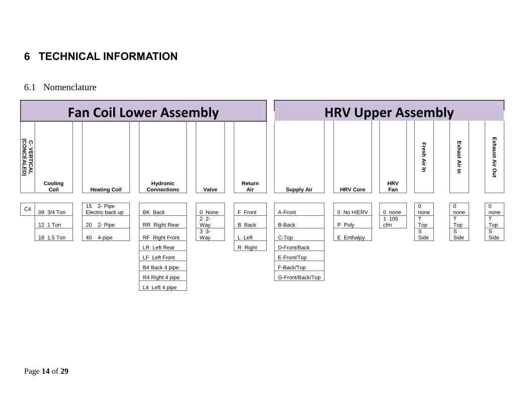
6 TECHNICAL INFORMATION
6.1 Nomenclature
Fan Coil Lower Assembly HRV Upper Assembly
C- V
ER
TIC
AL
(CO
NC
EA
LE
D)
Cooling Coil
Heating Coil
Hydronic Connections
Valve
Return Air
Supply Air
HRV Core
HRV Fan
Fre
sh
Air In
Exh
ast A
ir In
Exh
au
st A
ir Ou
t
C4 09 3/4 Ton
15 2- Pipe Electric back up
BK Back
0 None
F Front
A-Front
0 No H/ERV
0 none
0 none
0 none
0 none
12 1 Ton
20 2- Pipe
RR Right Rear
2 2-Way
B Back
B-Back
P Poly
1 105 cfm
T Top
T Top
T Top
18 1.5 Ton
40 4-pipe
RF Right Front
3 3-Way
L Left
C-Top
E Enthalpy
S Side
S Side
S Side
LR Left Rear
R Right
D-Front/Back
LF Left Front
E-Front/Top
B4 Back 4 pipe
F-Back/Top
R4 Right 4 pipe
G-Front/Back/Top
L4 Left 4 pipe

Page 15 of 29
6.2 Coil Data
DETAILED COIL DATA
COIL CONSTRUCTION - MODLE
409 MODEL
412 MODEL
418 MODLE 409 MODEL 412 MODEL 418
TYPE - WATER WATER WATER WATER WATER WATER
FIN HEIGHT X FINNED LENGTH UOM 20X10 20X10 20X10 20X10 20X10 20X10
FACE AREA SQ FT 1.39 1.39 1.39 1.39 1.39 1.39
FINS PER INCH ea 14 14 14 14 14 14
NOMINAL TON Ton 0.75 1 1.5 0.75 1 1.5
TUBE OD in 3/8 3/8 3/8 3/8 3/8 3/8
ROWS ea 3 3 4 3 3 4
AIR SIDE PERFORMANCE COOLING HEATING
FLOW cfm 350 450 500 350 350 350 450 450 450 500 500 500
CONTINUOUS LOW SPEED cfm 133 113 95 133 133 133 113 113 113 95 95 95
ENTERING AIR DRY BULB F 80 80 80 70 70 70 70 70 70 70 70 70
ENTERING AIR WET BULB F 67 67 67 60 60 60 60 60 60 60 60 60
LEAVING AIR DRY BULB F 56.1 56.2 54.1 162 145 111 161 145 111 171 152 115
LEAVING AIR WET BULB F 56 56 54.1
FACE VELOCITY fpm 252 324 360 252 252 252 324 324 324 360 360 360
LIQUID SIDE PERFORMANCE
ENTERING WATER TEMPERATURE F 45 45 45 180 160 120 180 160 120 180 160 120
LEAVING WATER TEMPERATURE F 57.8 57.4 55.6 141 128 103 143 130 103 150 135 103
NUMBER OF CIRCUITS ea 2 3 5 2 2 2 3 3 3 5 5 5
FLUID FLOW gpm 1.88 2.5 3.75 1.88 1.88 1.88 2.50 2.50 2.50 3.75 3.75 3.75
WATER PRESSURE DROP ft 10.47 6.42 5.59 8.52 8.71 9.26 5.29 5.42 5.71 4.74 4.83 5.06
TOTAL CAPACITY Btu/hr 12100 15500 19900 35,300
29,000
13,340
45,100
37,100
11,870
55,500
45,700
25,300
SENSIBLE CAPACITY Btu/hr 9200 11800 14300

Page 16 of 29
6.3 4-pipe Heating coil data
4-pipe fan coils use a single row coils in a common case with one of the cooling coils listed above. The heating performance of this coil is as
follows.
4-PIPE HEATING COIL DATA 20 degree delta 40 degree delta
COIL CONSTRUCTION MODLE 409 MODEL 412 MODEL 418 MODLE 409 MODEL 412 MODEL 418
TYPE WATER WATER WATER WATER WATER WATER
FIN HEIGHT X FINNED LENGTH 20X10 20X10 20X10 20X10 20X10 20X10
FACE AREA 1.39 1.39 1.39 1.39 1.39 1.39
FINS PER INCH 14 14 14 14 14 14
TUBE OD 3/8 3/8 3/8 3/8 3/8 3/8
ROWS 1 1 1 1 1 1
AIR SIDE PERFORMANCE HEATING HEATING
FLOW 350 350 350 450 450 450 500 500 500 350 350 350 450 450 450 500 500 500
ENTERING AIR DRY BULB 70 70 70 70 70 70 70 70 70 70 70 70 70 70 70 70 70 70
ENTERING AIR WET BULB 60 60 60 60 60 60 60 60 60 60 60 60 60 60 60 60 60 60
LEAVING AIR DRY BULB 137.5 122 90.9 130.9 116.8 88.6 128.1 114.6 87.7 122.7 106.7 90.4 117.2 102.6 88 114.9 101 87.1
FACE VELOCITY 252 252 252 324 324 324 360 360 360 252 252 252 324 324 324 360 360 360
LIQUID SIDE PERFORMANCE
ENTERING WATER TEMPERATURE 180 160 120 180 160 120 180 160 120 180 160 140 180 160 140 180 160 140
LEAVING WATER TEMPERATURE 160 140 100 160 140 100 160 140 100 140 120 100 140 120 100 140 120 100
NUMBER OF CIRCUITS 1 1 1 1 1 1 1 1 1 1 1 1 1 1 1 1 1 1
FLUID FLOW 2.67 2.042 0.813 3.10 2.36 0.93 3.285 2.511 0.98 1.043 0.722 0.4 1.20 0.83 0.45 1.27 0.871 0.478
WATER PRESSURE DROP 7.13 4.41 0.83 9.48 5.81 1.07 10.6 6.52 1.18 1.22 0.63 0.2 1.59 0.81 0.26 0.088 0.087 0.29
SENSIBLE CAPACITY 25939 19978 8046 30112 23125 9213 31940 24524 9715
20,271
14,119
7,853
23,337
16,141
8,891
24,676
17,026
9,384

Page 17 of 29
6.4 Fan Curves
The room fan coil is usually designed for free air delivery into a room but may be used
with minimal ducting having a static resistance of 0.25 inwc or less. The supply fan is
powered by an ECM operating in constant CFM mode. The delivered airflow remains
relatively constant over varying external static pressures
The supply fan also draws outside air through the HRV. The ratio of outside air and
return air is governed by the relative amounts of static pressure in the return air stream
and outside air stream. A dampered return air grille is supplied with each unit. Closing
this damper will create more return air static and result in more outside air.
CF
M
ESP (inwc)
SUPPLY FAN
C409
C412
C418

Page 18 of 29
6.5 Outside Air at Low Speed
The flow rate of outside air is a function of the main blower speed reduction from high
speed to circulation speed and to a lesser extent the duct system. The low speed outside
air flow cannot be adjusted without affecting the high speed flow rate. In most
applications the high speed ventilation rate is set during commissioning and the low
speed flow is left to float. You should expect low speed flow reductions of 40 – 60%.
6.6 Exhaust Air
Low speed range 40%-100% of high
CF
M
ESP (inwc)
HRV Exhaust Air

Page 19 of 29
6.7 HRV Efficiency
CORE OA TEMP OA FLOW EFFECTIVNESS
C F l/s cfm SENSIBLE LATENT
POLY
1.7 35 24 50 69 1.7 35 19 40 78 35.0 95 24 50 72 35.0 95 19 40 82
ENTHALPY
1.7 35 24 50 74 53 1.7 35 19 40 75 58 35.0 95 24 50 83 43 35.0 95 19 40 85 47
6.8 Sound Level Summary
Measured at 2.0 m from unit
SOUND LEVEL
MODEL LOW HIGH HEAT HIGH VENT
NC dBA NC dBA NC dBA
C409 27 34 42 34 47 33
C412 26 46 49 52 46 52
C418 26 50 48 52 47 54
6.9 Shop Drawings
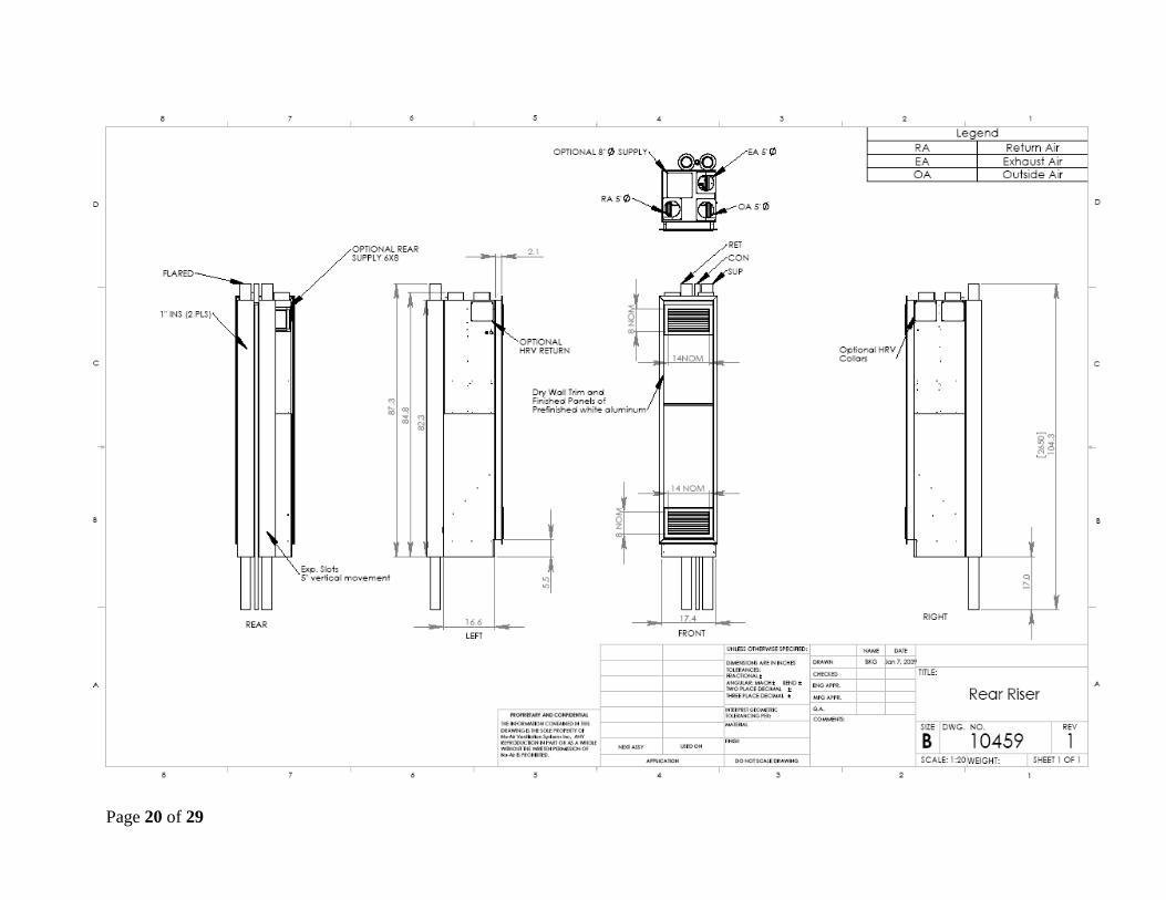
Page 20 of 29

Page 21 of 29
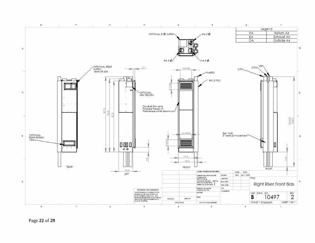
Page 22 of 29

Page 23 of 29

Page 24 of 29

Page 25 of 29
6.10 Electrical
No Electric Back up 120/1 400 15
1.5 kW Back up 120/1 1900 20
CONTROLS
POWER CONDUCTOR WIRES
THERMOSTAT 24 VAC 4 18 GA
DEHUMIDISTAT 24 VAC 2 18 GA
TIMERS 24 VAC 2 18 GA
TIMERS 24 VAC 3 18 GA
SPRING WOUND MECHANICAL COUNT DOWN
20-80% MAKE ON RISE
DESCRIPTION
HEAT COOL WITH FAN SWITCH
Momentary push button WIN-20
Page 26 of 29

Page 27 of 29
Page 28 of 29
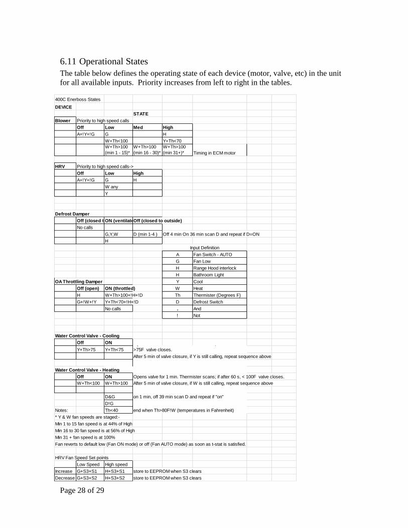
6.11 Operational States
The table below defines the operating state of each device (motor, valve, etc) in the unit
for all available inputs. Priority increases from left to right in the tables.
400C Enerboss States
DEVICE
STATE
Blower Priority to high speed calls
Off Low Med High
A+!Y+!G G H
W+Th<100 Y+Th<70
W+Th>100
(min 1 - 15)*
W+Th>100
(min 16 - 30)*
W+Th>100
(min 31+)* Timing in ECM motor
HRV Priority to high speed calls->
Off Low High
A+!Y+!G G H
W any
Y
Defrost Damper
Off (closed to outside)ON (ventilate)Off (closed to outside)
No calls
G,Y,W D (min 1-4 ) Off 4 min On 36 min scan D and repeat if D=ON
H
Input Definition
A Fan Switch - AUTO
G Fan Low
H Range Hood interlock
H Bathroom Light
OA Throttling Damper Y Cool
Off (open) ON (throttled) W Heat
H W+Th>100+!H+!D Th Thermister (Degrees F)
G+!W+!Y Y+Th<70+!H+!D D Defrost Switch
No calls ₊ And
! Not
Water Control Valve - Cooling
Off ON
Y+Th>75 Y+Th<75
After 5 min of valve closure, if Y is still calling, repeat sequence above
Water Control Valve - Heating
Off ON Opens valve for 1 min. Thermister scans; if after 60 s, < 100F valve closes.
W+Th<100 W+Th>100 After 5 min of valve closure, if W is still calling, repeat sequence above
D&G on 1 min, off 39 min scan D and repeat if "on"
D!G
Notes: Th<40 end when Th>80F!W (temperatures in Fahrenheit)
* Y & W fan speeds are staged:-
Min 1 to 15 fan speed is at 44% of High
Min 16 to 30 fan speed is at 56% of High
Min 31 + fan speed is at 100%
Fan reverts to default low (Fan ON mode) or off (Fan AUTO mode) as soon as t-stat is satisfied.
HRV Fan Speed Set points
Low Speed High speed
Increase G+S3+S1 H+S3+S1 store to EEPROM when S3 clears
Decrease G+S3+S2 H+S3+S2 store to EEPROM when S3 clears
Opens valve for 1 min. Thermister scans; if after 60 s
>75F valve closes.
Page 29 of 29
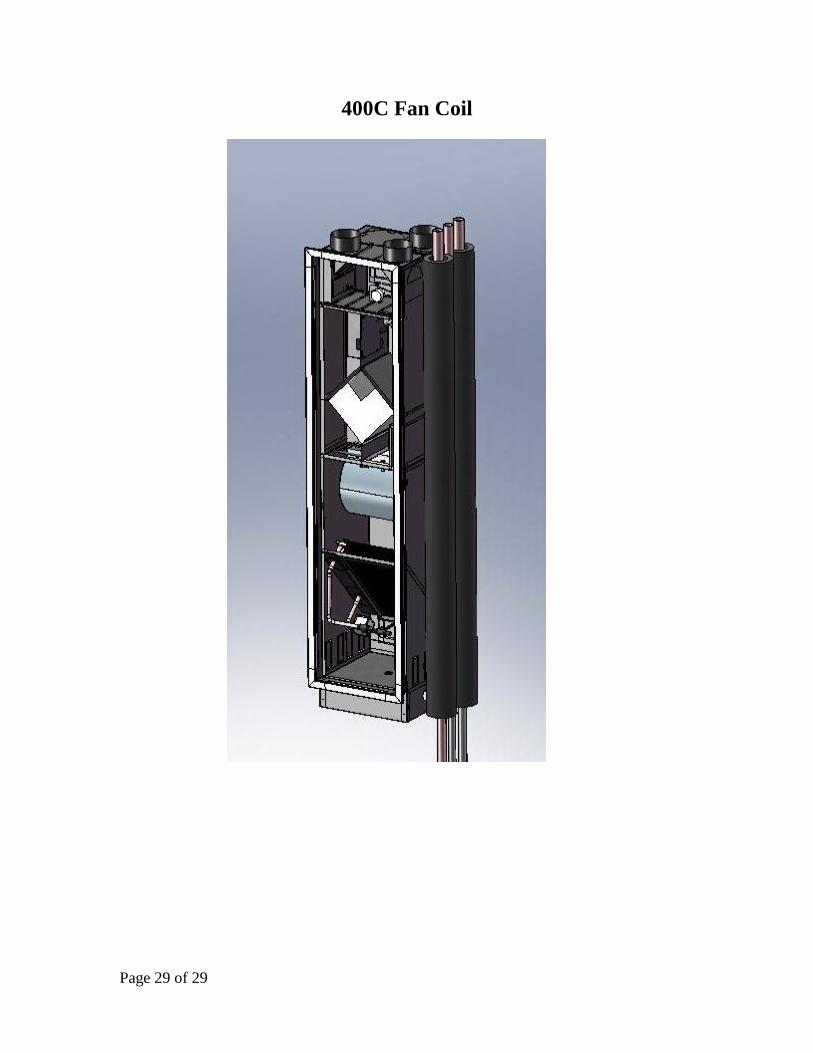
400C Fan Coil