energization of multi-terminal half-wavelength ...simulations were realized with matlab and anarede,...
TRANSCRIPT

Energization of Multi-Terminal Half-Wavelength Transmission Line
A. M. P. Mendes, M. C. Tavares, L. M. N. de Mattos
Abstract--The half-wavelength AC transmission system
(HWL) is an option to transport expressive amounts of energy for a very long distance, in a point-to-point link. This paper proposes the insertion of a rather long tap branch in between the HWL terminals, making it a multipoint network configuration. In doing so, this mesh allows the interconnection of a power plant and two different load centers, with neither substations nor reactive compensation along the line.
The present paper focus in the electromagnetic transients energization studies, on sound condition, whose promising results stimulate further researches towards both point-to-point and multi-terminal HWL AC transmission systems.
Keywords: AC-link, half-wavelength, multi-terminal, ATP,
switching overvoltages, Electromagnetic transients.
I. INTRODUCTION
RAZIL is the fifth-largest country in the world, the third largest in the Americas, with a total area of
8,515,767 km2, and its energy matrix is essentially based on hydroelectric sources [1]. Another relevant aspect of Brazilian territory concerns the location of the hydroelectric potential still unexplored: the major amount estimated and already studied by the Power Research Company (EPE) is located in the North Region, summing up to 29,232 GW and 39,855 GW, respectively [2]. On the other hand, the loads are concentrated on the South-East and Mid-West regions and represents 61.4 % of the Brazilian Interconnected Power System (SIN) total demand, over 2000 km far from the potential sources [3].
The characteristic of the load center being very far from the major generation sources is similarly verified in large countries, for instance, Russia, China and India. In the same way, it could be experienced in interconnections between countries, such as in the European and African continents.
One option to link sources and loads that are very distant from themselves is the HWL [4]. It consists, basically, on a rather long AC transmission system which takes advantage of voltage phasor angle shift along the line, ensuring that both terminals will have the same voltage magnitude, displaced by A. M. P. Mendes is M.Sc. student at University of Campinas, Brazil and is with Eletrobras Eletronorte, Brazil (e-mail of corresponding author: [email protected]). M. C. Tavares is with University of Campinas, Brazil (e-mail: [email protected]). L. M. N. de Mattos is M.Sc. student at University of Campinas, Brazil and is with Potência Engenharia, Brazil (e-mail: [email protected]). Paper submitted to the International Conference on Power Systems Transients (IPST2017) in Seoul, Republic of Korea June 26-29, 2017
180°, when energized through only one of its terminals. The major practical benefit of HWL is to allow a very long AC line with virtually no reactive compensation, to prevent high sustained voltages on the open line ending. This condition can be achieved by a transmission line with physical length of half-wavelength (λ/2) of its rated power frequency, or artificially tuning shorter lines, as presented in [5].
A possible drawback of HWL, in some scenarios, is its inherently point-to-point characteristic, meaning the impossibility to feed intermediary load centers in between its terminals. There are currently some research to tackle this issue, although the loads are drained directly from the HWL, without additional transmission lines (TL) and in reduced amounts [6], [7], [8].
Considering the aforementioned issues, the authors are involved in a research in which the main object is to conceive a transmission system that allows the interconnection of more than one receiving end in an HWL line, from now on denominated multi-terminal (MTHWL).
The current research began with the investigation of a tap branch connection, deriving from the main HWL trunk, aiming the optimum insertion location and the tap length, constrained by operative limits. Another design requirement was to permit the interconnection of actual SIN substations.
Based on preceding specification, one MTHWL topology was selected from a large solution set, which is able to transfer bulk energy from one source to two load centers.
To prove thoroughly the safety and reliability of the selected MTHWL configuration operation, several analyses are needed, such as: steady state studies for many load profiles, transient stability and electromagnetics transients simulations, regarding to equipment specification.
The main focus of the present paper is to evaluate the transients overvoltages and overcurrents which the electric network will be subject during the energization of MTHWL system, and its comparison with a regular HWL.
The MTHWL feasibility investigation and power flow simulations were realized with MATLAB and ANAREDE, respectively. The time domain digital simulations were performed with Alternative Transients Program (ATP).
II. SYSTEM CONFIGURATION
The studies started with the investigation of viable setups of generation-load interconnection by means of MTHWL, concerning the following steady state criteria:
1. Open line energization: a. Sending end voltage equal to 0.95 pu;
B
b. Voltage magnitude on both receiving ends less than or equal to 1.1 pu.
2. Load flow at natural power transmission (SIL – surge impedance loading): a. Sending end voltage magnitude equal to 1.0 pu,
phase 0°; b. Voltage magnitude on both receiving ends greater
than or equal to 0.95 pu and less than or equal to 1.05 pu;
c. Phase shift between sending and each receiving end not less than 190º and not greater than 210º, due to stability concerns.
Furthermore, three power flow scenarios were chosen: I. 70 % of SIL delivered on the main branch and
30 % on the drain branch; II. 60 % of SIL delivered on the main branch and
40 % on the drain branch; III. 50 % of SIL delivered on the main branch and
50 % on the drain branch.
In doing so, numerical solutions were carried out on MATLAB until converge to a solution set of configurations from where was chosen the grid to be studied with the following characteristics (Fig. 1):
• 60 % of SIL delivered on the main branch and 40 % on the drain branch;
• Drain branch of 220 km long; • Point of drain connection 40 km far from main
branch end.
Fig. 1. Single line diagram of the electric network for the MTHWL energization.
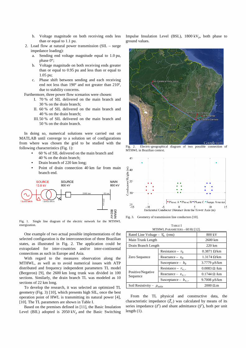
One example of two actual possible implementations of the selected configuration is the interconnection of three Brazilian states, as illustrated in Fig. 2. The application could be extrapolated for inter-countries and/or inter-continental connections as such in Europe and Asia.
With regard to the measures observation along the MTHWL, as well as to avoid numerical issues with ATP distributed and frequency independent parameters TL model (Bergeron) [9], the 2600 km long trunk was divided in 100 sections. Similarly, the drain branch TL was modeled as 10 sections of 22 km long.
To develop the research, it was selected an optimized TL geometry (Fig. 3) [10], which presents high SIL, once the best operation point of HWL is transmitting its natural power [4], [10]. The TL parameters are shown in Table I.
Based on the premises defined in [11], the Basic Insulation Level (BIL) adopted is 2050 kVp and the Basic Switching
Impulse Insulation Level (BSL), 1800 kVp, both phase to ground values.
Fig. 2. Electric-geographical diagram of two possible connection of MTHWL in Brazilian context.
Fig. 3. Geometry of transmission line conductors [10].
TABLE I MTHWL PARAMETERS – 60 HZ [12].
Rated Line Voltage – (rms) 800 kV
Main Trunk Length 2600 km
Drain Branch Length 220 km
Zero Sequence
Resistance – 0.3871 Ω/km
Reactance – 1.3174 Ω/km
Susceptance – 3.7779 µS/km
Positive/Negative Sequence
Resistance – , 0.0083 Ω /km
Reactance – , 0.1744 Ω /km
Susceptance – , 9.7008 µS/km
Soil Resistivity – 2000 Ω.m
From the TL physical and constructive data, the
characteristic impedance () was calculated by means of its series impedance (′) and shunt admittance (′), both per unit length (1).

′ ′ 134.1256 !3.1945Ω (1)
The SIL is then calculated by (2):
$%& || (800000+,134.1637 4770./ (2)
The MTHWL was energized from a power plant consisting of 13 generators of 390 MVA, 13.8 kV, inserted in ATP as 14 source model [9], behind its subtransient reactance, X”d = 20 %. It was considered that the machines could operate with a terminal voltage equal to 0.90 pu to energize the MTHWL, only to the switching maneuver.
Each machine is connected to the MTHWL by means of its respective 13.8 kV/800 kV – 405 MVA step-up transformer (TF), whose Xps = 12 % in its rated base.
No surge arrester was considered on the simulation, in order to study the very maximum overvoltage peak possible to be obtained, as a result of the proposed MTHWL energization.
The three-phase short-circuit current (SCC) measured on the sending end 800 kV busbar is 9.367 kArms. The single-phase SCC is 11.875 kArms.
III. ENERGIZATION ASSUMPTIONS
As the MTHWL proposed is intended to be connected to SIN, the studies were guided by the Brazilian regulatory framework, specifically the Network Procedures (NP) [13], defined by the Brazilian Power System Operator (ONS).
Thus, the energization studies of both MTHWL endings simultaneously from the sending end switching, performed on ATP, were firstly developed statistically to identify the most critical cases in terms of transient overvoltage and overcurrent. The simulation settings consisted of 200 shots, processed for 500 ms, the circuit breaker (CB) was modeled as a statistical switch, with standard deviation equal to 1.5 ms. The average time, 14.7 ms, was chosen so that the CB closing occurred at the maximum voltage at the line end, and no switching control method was taken into account.
The time step was calculated by (3), considering the modeled system time constants and the typical frequencies involved on the maneuver, focusing on the shortest line section length of 22 km travelling time. The divisor factor 10 intends to avert excessive magnitude and phase distortions placed by the trapezoidal integration rule.
0 2210 .11 7.6μs (3)
The cases with most expressive overvoltages for the points of greater interest were then reproduced in deterministic simulations. The referred points are:
1. Sending end; 2. Highest overvoltage point along the line; 3. Main branch receiving end; 4. Drain branch receiving end.
The pre-energization voltage was 0.9 pu to achieve smaller overvoltages peaks as possible, across the entire MTHWL system, during the energization. It was considered as acceptable transient overvoltages the values described in Table II, taken from NP [13].
TABLE II
REFERENCE VALUES FOR ADMISSIBLE TRANSIENT OVERVOLTAGES [13]
Voltage (pu) Time (s) 2.00 0.1667 (10 cycles) 1.82 0.3333 (20 cycles) 1.50 1.667 (100 cycles) 1.40 3.6 1.35 10 1.25 20 1.20 60 1.15 480
In addition to the Table above, [13] defines: for time span
shorter than 10 cycles of fundamental frequency, the transient voltages may not be higher than BSL, considering a safety margin of 15 %.
Intending to have a reference result, it was developed the energization of the HWL with no drain connected, modeled considering the very same MTHWL parameters, equal pre-energization conditions, and software adjusts.
For a better understanding of the sustained overvoltages at the end of energization maneuver, a steady state voltage profile comparison between MTHWL and HWL is provided, being both switched only from source terminal. In both cases, the sending end voltage was set to 0.97 pu in order to assure a maximum voltage of 1.1 pu in the two MTHWL open ends.
IV. RESULTS AND ANALYSIS
A. Steady State
The voltage profile in steady state is shown in Fig. 4, for both MTHWL and HWL, with the same voltage adjusted at the source terminal. It is possible to notice that, due to the capacitive admittance added to the line by its drain branch, the MTHWL presents higher sustained voltages, as expected. The voltage at both MTHWL receiving ends are considerably higher than at the sending end, as a consequence. Moreover, the more expressive voltages, along MTHWL main trunk, occurs on the first half region, which is a typical behavior of a HWL when its second half terminal is in the condition of absorbing reactive power [14].
In addition to the aforementioned peculiarities, related to the insertion of reactive power by the drain branch, the MTHWL presents similar voltage profile in the central region when compared to the HWL, with a slight right shift [14].
B. Time Domain Energization
Since it is not planned any substation along the MTHWL, the maneuver was proceeded by the CB closure at the sending end (source busbar), energizing both drain and main branch ends simultaneously. The most severe overvoltages observed along the line, during the energization, are presented in Fig. 5,

for both MTHWL and HWL. Comparing to the HWL, the MTHWL overvoltages are
similar on the second half region, particularly at the main branch receiving end. This can be explained by the fact that the pre-energization voltage was set to be the same, as well as
all the TL physical characteristics. The deterministic simulations considering the closing time
which gives the most critical overvoltage, for the points of interest, and overcurrent, through the circuit breaker, are presented in Figs. 6 to 8.
Fig. 4. Steady state voltages along the MTHWL and HWL.
Fig. 5. Most severe overvoltages along the MTHWL and HWL during the respective energization.
0
0,2
0,4
0,6
0,8
1
1,2
Drain Branch Lengh (km)
Vo
ltage
(pu
)
Main Branch Lengh (km)
Main Branch
Drain Branch
HWL
1
1,25
1,5
1,75
2
2,25
2,5
Drain Branch Lengh (km)
Vo
ltage
(p
u)
Main Branch Lengh (km)
Main BranchDrain BranchHWL

From Fig. 6 it is possible to observe that, at the sending end, the voltage response was smooth, presenting a single peak of 1.67 pu, decreasing rapidly.
Fig. 7 shows the voltage at the point in which the highest voltage peak is measured along the main trunk of the MTHWL, 364 km far from sending end, i.e., disregarding the receiving ends. It can be seen the appearance of a single peak of 2.31 pu, quickly damped to moderate values.
The most critical overvoltage occurred at the drain branch end (Fig. 8), on phase C. In that case, the overvoltage is severe, 2.45 pu, of the order of 88 % BSL, but consists of a single peak. This is an acceptable result, once the line was not represented with frequency dependent model [15] and no mitigation method was considered, as pre-insertion resistor and terminal surge arresters which would manage to reduce the overvoltage.
The overvoltage obtained at the main branch receiving end (Fig. 9), 2.16 pu, is smaller than the observed in the drain branch terminal, as well as the one at the point 364 km far from the source busbar.
All the voltages responses, in time, show the characteristic of being promptly damped, whose maxima consists of a single peak, surrounded by others much smaller and fast tending to acceptable values, in accordance with NP (Table II - [13]).
The higher transient overvoltages visualized in the MTHWL are related to the constructive interference, once the drain branch inserts in the main trunk wave fronts time delayed from the ones reflected on main branch terminal. Compositions of switching traveling waves, which reflects in both terminals, on top of the higher sustained response imposed by the capacitive admittance, provided by the drain branch, results on the peaks measured.
Regarding the current flowing through the switched circuit breaker during the energization, Fig. 10 shows that the maximum peak, 7.98 kAp, experimented by phase C, was reasonable, being about two times the current for SIL power flow. If compared to the short-circuit level on the sending end bus, as defined in Section II, this value is about 60 % of three-phase SCC.
In Fig. 10 is also noticeable that the current briefly misses the zero crossing around 100 ms, in phases A and B. It is a characteristic usually found during HWL energization maneuver. As matter of fact, it is possible to visualize the same pattern in the voltage curves presented in Figs. 7 to 9 and 11, as in [16].
Fig. 6. Voltage on the sending end during the energization – MTHWL.
Fig. 7. Voltage on the most critical point during the energization (364 km from sending end) – MTHWL.
Fig. 8. Voltage on the drain branch end during the energization – MTHWL.
Fig. 9. Voltage on the main branch end during the energization – MTHWL.
Fig. 10. Current through the energization circuit breaker – MTHWL.
Fig. 11. Voltage on the receiving end during the HWL energization.

The deterministic energization study developed for the HWL, with no drain connected, presented the maximum overvoltage at the receiving end (Fig. 11), phase C, similar to MTHWL at this same line position (Fig. 9). However, the maximum peak appearance does not manifest at analogous instant and the beating frequencies are somewhat different.
THE Table III presents a synthesis of the maximum overvoltages
results, in the main points along the line, for transient (statistical switches) and steady state.
TABLE III
TRANSIENTS AND STEADY STATE VOLTAGES ALONG MTHWL AND HWL.
Location Transient Voltage
(pu) Steady State Voltage
(pu) MTHWL HWL MTHWL HWL
Sending End 1.67 1.45 0.97 0.97 364 km from sending end (1)
2.31 1.78 1.12 0.97
Main Branch End 2.16 2.17 1.057 1.00 Drain Branch End 2.45 ---- 1.10 ---- (1) Highest overvoltage along line during the MTHWL energization.
V. CONCLUSIONS
In the present paper, the time domain energization of a multi-terminal half-wavelength AC transmission line (MTHWL) was presented, analyzed and also compared with a regular half wavelength transmission line (HWL).
The observed overvoltages in the MTHWL unfaulted energization shows an expressive high single spike, however it is promptly damped, being therefore an acceptable result. In contrast, the currents measured in the switching CB are not of important magnitude, since it is only slightly greater than 0.5 SCC3φ. Hence, the selected MTHWL topology energization, under sound conditions, proved itself viable and not requiring any special mitigation strategy.
In accordance with the presented results, further research in both HWL and MTHWL technologies are encouraged, as promising solutions to transfer bulk energy blocks through long distances, in point-to-point or multi-terminal manner, respectively.
VI. REFERENCES [1] Power Research Company - EPE, “Brazilian Energy Balance 2015:
year 2014”. 2015 Retrieved from https://ben.epe.gov.br/. [2] Eletrobras, “Map of Brazilian Hydroelectric Potential - November
2014” 2014. [3] Electric System National Operator - ONS, “Relevant Data 2013 -
ONS,” 2013. [Online]. Retrieved from https://www.ons.org.br/download/biblioteca_virtual/publicacoes/dados_relevantes_2013/html/01-07-destaques.html. [Accessed: 11-Jul-2015].
[4] F. Hubert and M. Gent, “Half-Wavelength Power Transmission Lines” IEEE Power Apparatus and Systems, pp. 87–92, 1965.
[5] J. A. Santiago and M. C. Tavares, “Electromagnetic Transient Study of a Transmission Line Tuned for Half Wavelength,” in International Conference on Power Systems Transients – IPST, Wroclaw, Croatia, 2015, p. 7.
[6] M. C. Tavares and R. Torquato, “Attending small loads along a half-wavelength transmission line,” 2011 IEEE Electr. Power Energy Conf. EPEC 2011, Winnipeg, Canada, pp. 255–259, 2011.
[7] M. Aredes, C. Portela, E. L. Van Emmerik, and R. F. Da Silva Dias,
“Static series compensators applied to very long distance transmission lines,” Electr. Eng., vol. 86, no. 2, pp. 69–76, 2004.
[8] M. Aredes and R. F. S. Dias, “Comparisons between a Series and a shunt FACTS for tapping and power flow control in half-wavelength transmission lines,” 2012 15th Int. Power Electron. Motion Control Conf., p. DS3b.20-1-DS3b.20-7, Sep. 2012.
[9] Argentinean Committee of EMTP - ATP Users - CAUE, “ATP - Alternative Transient Program Rule Book,” 1987.
[10] C. M. Portela, “Non-Conventional AC Solutions Adequate for Very Long Distance Transmission,” in XI Symposium of Specialists in Operation Planning and Electrical Expansion (SEPOPE), 2009, pp. 1–11.
[11] “IEEE Standard for Insulation Coordination — Definitions, Principles, and Rules,” IEEE Std C62.82.1-2010 (Revision IEEE Std 1313.1-1996), pp. 1–22, 2011.
[12] M. C. Tavares, R. B. Borges, and C. M. Portela, “Analysis of an Isolated Half-Wavelength Transmission Line Submitted to Switching Maneuvers,” in 2011 Asia-Pacific Power and Energy Engineering Conference (APPEEC), Wuhan, China, Mar, 2011, pp. 1–5.
[13] Electric System National Operator - ONS, “Guideline and Criteria for Electrical Studies - Item 23.3,” 2011.
[14] R. F. Vidigal and M. C. Tavares, “Fundamental Concepts of a Transmission Line Little Longer than Half-Wavelength, "in 2010 Brazilian Symposium on Electrical Systems (SBSE), Belém, Brazil, 2010, pp. 1–6.
[15] P. Gómez, “Performance Evaluation of Time Domain Transmission Line Models for a Statistical Study of Switching Overvoltages,” IEEE Lat. Am. Trans., vol. 11, no. 4, pp. 1036–1046, 2013.
[16] E. C. Gomes and M. C. Tavares, “Analysis of the Energization Test of a Half-Wavelength AC Link Composed of Similar Transmission Lines,” 2011 APPEEC, Wuhan, China, pp. 1–5, Mar. 2011.