energy and the affordable future fleet - doerry home...
TRANSCRIPT

1 Approved for Public Release Distribution is Unlimited
Energy and the affordable future fleet Norbert H. Doerry, PhD, Timothy J. McCoy, PhD, Thomas W. Martin
United States Navy
SYNOPSIS Volatile and rapidly rising energy costs are one of the top challenges for all nations and their defense organizations. Despite a reduction in force structure and increased conservation efforts over the past several years, the rapid increase in energy costs has placed significant pressure on the U.S. Navy budget. Reducing fuel consumption is an operational and strategic imperative and has a direct impact on improving warfighting effectiveness. The U.S. Navy is exploring opportunities to increase the energy efficiency of our non-nuclear ships and reduce total fossil fuel consumption across the fleet. This paper describes the efforts the U.S. Navy is currently undertaking as well as planning to accomplish to achieve these goals.
INTRODUCTION
Volatile and rapidly rising energy costs are one of the top challenges for all nations and their defense organizations. The U.S. Navy is facing a major challenge to sustain and operate its current and future force structure within the projected budgets. Despite a reduction in force structure and increased conservation efforts over the past several years, the rapid increase and uncertainty in energy costs has placed considerable pressure on the Navy budget. Figure 1 shows this volatility through the price the Defense Energy Support Center (DESC) has charged its defense customers for a barrel of F-76, the distillate fuel normally used in U.S. Navy shipboard diesels, gas turbines, and boilers. Since 2006, the price for F-76 has changed 13 times, with a low of $60.06 per barrel and a high of $170.52 per barrel.
U.S. Navy’s ships consumed 10.1 million barrels of fuel in 2008. The Navy’s Task Force Energy (TFE) projects an increase of 20 to 25% by 2020. This is due to the introduction of several new ships to the fleet, increasing energy demand for new capabilities, along with a corresponding increase in operating hours.
Authors’ Biography Dr Norbert Doerry is presently the Senior Scientist in the NAVSEA SEA 05 Technology Office. He retired in 2009 as a Captain in the U.S. Navy with 26 years of commissioned service, 23 years as an Engineering Duty Officer. In his final billet, he served for nearly six years as the Technical Director for Surface Ship Design. Dr Doerry is a 1983 graduate of the United States Naval Academy and a 1991 graduate of MIT. He is the 2008 recipient of the ASNE Gold Medal. He is a member of ASNE, SNAME, IEEE and the Naval Institute and has published over 25 technical papers. Dr. Timothy McCoy serves as Director of the Electric Ship’s Office (PMS-320) within the Program Executive Office for Ships. There, he is responsible for developing electric power and propulsion systems for the US Navy’s fleet. Prior to entering government service, he worked in industry as R&D Director and President of a defense contractor. Previously, he served on active duty in the US Navy. Dr. McCoy’s 26 years of experience includes development of integrated electric power and propulsion systems and design and construction for several classes of ships. Dr. McCoy holds a BSME from the University of Illinois, a Naval Engineer’s Degree, SMEE and PhD from MIT and has taught ship design and systems engineering while on the MIT faculty. He is a registered Professional Engineer, is a member of ASNE, IMarEST, SNAME, a senior member of the IEEE and has published over 35 technical papers. Mr. Thomas Martin is presently the Technical Warrant Holder/Supervisor for Machinery Integration in the Marine Engineering Group at Naval Sea Systems Command. He is assigned as NAVSEA’s representative to the U.S. Navy’s Task Force Energy, is a member of the Navy Energy Coordination Office, and is the co-lead for the Maritime Energy Working Group. He has 25 years experience as a marine engineer in the area of naval surface combatant design, acquisition, and life cycle support. Mr. Martin holds a BS in Physics from Ithaca College (’87) and BS in Mechanical Engineering from Rochester Institute of Technology (’87).

2 Approved for Public Release Distribution is Unlimited
Fig 1 Defense Energy Support Center price for F-76 fuel
Reducing fuel consumption is an operational and strategic imperative and has a direct impact on improving warfighting effectiveness. The United States Maritime Strategy1 is about Security, Stability and Seapower. The core capabilities of maritime power to achieve this strategy are Forward Presence, Deterrence, Sea Control, Power Projection, Maritime Security, Humanitarian Assistance and Disaster Response. Fuel efficiency enhances these capabilities by improving endurance, improving operational flexibility, and supporting forward presence and distributed operations, while reducing vulnerability of a long supply line.
While the Navy also expends a significant amount of fuel in its aircraft, this paper focuses on some of the efforts the U.S. Navy is currently undertaking as well as planning to accomplish to increase the energy efficiency / reduce total fossil fuel consumption of non-nuclear ships. These efforts can be grouped into the following categories:
• Improved prime mover efficiency
• Reduced propulsion power demand
• Reduced mission systems and ship systems power demand
• Modifying Concepts of Operation (CONOPS) to achieve mission objectives with less fuel consumption
Much of the future fleet is already at sea today, mainly because U.S. warships typically have a 30 to 40 year service life. Consequently, near term efforts are centered on what can be done to existing ships and ship designs. In the future, the U.S. Navy is committed to developing the Next Generation Integrated Power System (NGIPS) to provide fuel efficient and affordable power systems meeting the operational needs of the fleet. The U.S. Navy is also working on additional technologies to reduce electrical demand.
BACKGROUND
Figure 2 shows where the fossil fuel is used in a mechanical-drive ship. This architecture constitutes the majority of the U.S. fleet. Figure 3 similarly shows the fossil fuel usage in an integrated propulsion system (IPS) ship. From these functional descriptions, we can see that losses occur in each power conversion process (whether chemical to mechanical, mechanical to electrical, electrical to mechanical or otherwise). The majority of the losses occur in the diesel or gas turbine prime movers that create mechanical power from the fossil fuel. The second largest loss of efficiency occurs in turning the mechanical power input to the propellers into ship movement. Whether mechanical or electrical, the transmission systems between these components are relatively efficient when compared to these two areas.

3 Approved for Public Release Distribution is Unlimited
Fig 2 Losses in Mechanical Drive Ship
However, many features of a particular ship are essentially locked-in once constructed because they are prohibitively expensive to change once in service. Examples of this are major changes to the underwater hullform or the type of propulsion transmission system. Consequently, many of the near-term efforts are focused on changing what can be done in an affordable manner. These initiatives have been grouped into four main categories: 1) Improved Prime Mover Efficiency; 2) Reduced Propulsion Power Demand; 3) Reduced Mission and Ship System Load Demand; and 4) Modifications to concept of operations (CONOPS). The first three areas all involve some sort of technology insertion into the ship itself while maintaining the same mission requirements. The last area involves simply changing the policies and/or procedures in how we operate our ships.
Fuel Engines100% 35%generators
96%
65% to air 4% to sea
Propulsion Motor,Controller and Aux. loads
99%
1% to sea
Distribution
90%
10% to sea
Propeller,Pumps, HVAC,Combat systems
69%
31% to sea
Step energy efficiencyCumulative efficiency
35% 33.6% 33.2%
29.2% 20.6% WorkRadiated energy:AcousticElectromagneticKinetic
<1%
99%
<.2%
Fig 3 Losses in Integrated Electric Ship
Fuel
Main Engines 100%
35%*
Ship Service Generators
96%
70% to air 3 to 4% to sea
Main Red. Gear and Auxiliaries
99%
1% to sea
Electrical Distribution
91%*
9% to sea
Pumps, HVAC, Combat systems
60%*
40% to sea
Step energy efficiency Cumulative efficiency
35%
28.8% 28.5%
15.6% Ship drag, Radiated heat, Pipe and duct losses, Electrical losses, etc.
Work <1%
99% <.2%
* Efficiencies approximate for illustrative purposes.
98% 34%
Shaftline , Bearings, Stern tube
99% 33.9%
Ship Service Engines
30%* 30%
Motors and Power conversion
CRP Propeller 65%* 22.0%
25.9%
35% to sea Radiated energy: Acoustic Electromagnetic Kinetic

4 Approved for Public Release Distribution is Unlimited
TECHNOLOGIES
Improved prime mover efficiency
Gas Turbines
The U.S. Navy is exploring a broad spectrum of energy efficiency improvement opportunities for its large population of gas turbine engines. These initiatives include replacing analog fuel controls with digital fuel controls, modifying exhaust ducting to reduce back pressure, modifying internal components of the engines during their overhauls, and providing an automated online water wash capability. The automated online water wash enables more frequent cleaning of the gas turbine, without impacting operations, thereby improving efficiency. A prototype automated online Water Wash was demonstrated in 2009 on U.S.S. PREBLE (DDG 88). Fuel economy and maintenance costs are currently being evaluated.
Combustion Trim Loop for conventional steam ships
Existing amphibious assault ships sub-optimally control the forced draft blowers supplying combustion air for the main boilers. Excessive air decreases gas temperature and boiler efficiency, particularly at lower steaming rates. In 2009, the Navy installed on U.S.S. PELELIU (LHA 5) an improved Stack Gas Analyzer and a Programmable Logic Controller to send control signals to the existing boiler controls for trimming excess air. Testing is currently underway to verify the projected 2% to 3% reduction in fuel consumption. If the projections are confirmed, the Navy intends to install this system on the other amphibious assault ships.
Hybrid Electric Drive
As shown in Figure 4, Hybrid Electric Drive (HED) is a propulsion plant configuration using an electric motor attached to the main reduction gear (MRG) of a mechanical-drive (typically gas turbine powered) ship. HED enables higher efficiencies by using the ship service generators at low propulsion loading conditions (Low speeds) where the main propulsion gas turbines are least efficient. U.S.S. MAKIN ISLAND (LHD 8) is the first U.S. Navy amphibious assault ship to replace steam boilers with gas turbines, and the first Navy ship to be equipped with both gas turbines and an Auxiliary Propulsion System (APS) in a HED configuration. By using this unique propulsion system in conjunction with operational awareness of the crew, the ship saved approximately $2 million in fuel costs during her transit from Pascagoula, MS to San Diego, CA compared to a similar ship using steam boilers.
Instead of using gas turbines which are less efficient at lower speeds, the ship will be able to use APS for roughly 75 percent of the time the ship is underway. Over the course of U.S.S. MAKIN ISLAND's 40 year service life, the Navy expects to see a savings of more than $250 million. Because the gas turbines will be used infrequently, the Navy will also save on maintenance costs.
Fig 4 Hybrid Electric Drive2
The Navy is currently investing in a prototype demonstration of a Hybrid Electric Drive on a destroyer. Several industry and Navy studies have been completed recently which all show very large fuel savings are possible. The NSWC study completed in 2008 predicts 8.9% overall fuel savings3. The

5 Approved for Public Release Distribution is Unlimited
Navy plans to test the prototype system at the Land Based Engineering Site (LBES) in Philadelphia during 2010. This equipment is also intended for an at-sea demonstration during 2011-2012. The eventual goal is to have production systems at sea in the 2015-2016 time frame.
Reduced propulsion power demand
Stern Flaps
A stern flap (Fig 5) is an extension of the hull bottom surface aft of the transom. Stern flaps modify the flow of water under the hull afterbody, decreasing flow velocity and increasing pressure, resulting in reduced form drag, and thus, reduced hull resistance.
For ships with a transom stern, stern flaps have been proven to reduce propulsive power and exhaust emissions, and to foster significant fuel cost savings, while increasing both ship speed and range. Flaps also reduce propeller loading, cavitation, vibration, and noise.
Stern flaps are constructed with simple techniques similar to bilge keels, Attachment to the transom is with conventional welding on the ship’s exterior. Pay-back period to recoup fabrication and installation cost is on the order of 1-2 years.
Over the past ten years, the Navy has aggressively installed stern flaps on its surface combatants. For the FFG 7 class, Cave and Cusanelli estimated that the stern flap saved about 4% in annual fuel consumption4. The Navy is currently installing stern flaps on ships of the amphibious warfare fleet. The U.S.S. KEARSARGE (LHD 3) began evaluation of a stern flap in November 2009. A stern flap has also been installed on U.S.S. WHIDBEY ISLAND (LSD 41).
Fig 5 Stern Flap on DDG 51 Class Destroyer
Bulbous Bows
Bulbous bows are a bulb extending in front of the ship’s stem designed to create a wave that cancels the ship’s bow wave. Drag reductions on the order of 15% at the design speed are possible. Historically, bulbous bows have been primarily used for large, slender, mono-hulls that mostly operate near their design speed. More recently, advances in computational fluid dynamics have enabled bulbous bows that provide good performance off of design speed. Figure 6 shows the bulbous bow fitted on U.S.S. GEORGE H. W. BUSH (CVN 77)
Note that while many surface combatants have large sonar domes mounted on the bow, they are not specifically designed to reduce drag. Figure 7 shows the addition of a second bulb on a destroyer model for the purpose of reducing drag. Cusanelli reports that for a destroyer with the additional drag reduction bulb, resistance can be decreased by 7% at the cruise speed, and 3% at the maximum speed. Additionally, fuel consumption can be decreased by 4%.5

6 Approved for Public Release Distribution is Unlimited
Fig 6 Bulbous Bow on U.S.S. George H. W. Bush (CVN 77)
Fig 7 Addition of drag reduction bulb on a destroyer model with sonar dome
Hull and Propeller Coatings
A fouled hull can result in a 5% to 12% reduction in fuel efficiency. Historically, the U.S. Navy has used periodic inspections of ship's hulls by divers to determine if mechanically cleaning the hull was warranted. Recent advances in hull coating technology has resulted in commercial products that are extremely smooth. These smooth finishes offer less resistance when new and are resistant to fouling because marine life have difficulty adhering to it. Marine growth that manages to adhere to the coating while inport will typically wash away as the ship transits at its cruise speed. The minimum speed to release the fouling is a function of the hull geometry. Commercial ships have experienced an average reduction in fuel consumption on the order of 9%. In 2009, the Navy began a demonstration (fig 8) of a fouling release coating on U.S.S. PORT ROYAL (CG 73) and U.S.S. COLE (DDG 67). The Navy also installed Ship Power Condition Monitoring Systems (SPCM) on these ships and two control ships (U.S.S. BUNKER HILL CG 52 and U.S.S. GONZALES DDG 66) that have traditional bottom paint.

7 Approved for Public Release Distribution is Unlimited
The SPCM accurately measures and records the power and speed as a function of time. To date, the Navy has also performed twelve underwater hull inspections of the test and control ships to document fouling and correlate the fouling to SPCM data.
Results of this evaluation and comparison with the control ship performance will determine if the Navy more widely uses fouling release coatings. Underwater inspections of U.S.S. COLE have shown significant sloughing of fouling during transits to and from Europe. The major impediment to wide adoption of advanced fouling release coatings is the cost premium. The material cost for these coatings is about 2.7 times the traditional copper ablative coating. Overall, the total job cost premium, including labor, for the advanced coating is about 12% for cruisers and 15% for destroyers.
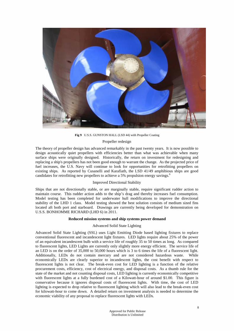
Recent successes in the commercial marine industry in improving propeller efficiency by using the same coating systems on the propellers has led to a Navy test of the concept on U.S.S. GUNSTON HALL (LSD 44), shown in Figure 9. Results of this testing are expected in 2010.
The U.S. Navy expects a relatively fast payback period for these coatings on the order of several years or less. Following the completion of testing and the verification of the return on investment, the U.S. Navy expects to make a decision on fleet wide implementation of advanced fouling release coatings in 2011.
Fig 8 U.S.S. COLE (DDG 67) with fuel efficient underwater hull coat paint
8 Approved for Public Release Distribution is Unlimited
Fig 9 U.S.S. GUNSTON HALL (LSD 44) with Propeller Coating
Propeller redesign
The theory of propeller design has advanced remarkably in the past twenty years. It is now possible to design acoustically quiet propellers with efficiencies better than what was achievable when many surface ships were originally designed. Historically, the return on investment for redesigning and replacing a ship's propellers has not been good enough to warrant the change. As the projected price of fuel increases, the U.S. Navy will continue to look for opportunities for retrofitting propellers on existing ships. As reported by Cusanelli and Karafiath, the LSD 41/49 amphibious ships are good candidates for retrofitting new propellers to achieve a 5% propulsion energy savings.6
Improved Directional Stability
Ships that are not directionally stable, or are marginally stable, require significant rudder action to maintain course. This rudder action adds to the ship’s drag and thereby increases fuel consumption. Model testing has been completed for underwater hull modifications to improve the directional stability of the LHD 1 class. Model testing showed the best solution consists of medium sized fins located aft both port and starboard. Drawings are currently being developed for demonstration on U.S.S. BONHOMME RICHARD (LHD 6) in 2011.
Reduced mission systems and ship systems power demand
Advanced Solid State Lighting
Advanced Solid State Lighting (SSL) uses Light Emitting Diode based lighting fixtures to replace conventional fluorescent and incandescent light fixtures. LED lights require about 25% of the power of an equivalent incandescent bulb with a service life of roughly 35 to 50 times as long. As compared to fluorescent lights, LED Lights are currently only slightly more energy efficient. The service life of an LED is on the order of 35,000 to 50,000 hours which is 3 to 6 times the life of a fluorescent light. Additionally, LEDs do not contain mercury and are not considered hazardous waste. While economically LEDs are clearly superior to incandescent lights, the cost benefit with respect to fluorescent lights is not clear. The break-even cost for LED lighting is a function of the relative procurement costs, efficiency, cost of electrical energy, and disposal costs. As a thumb rule for the state of the market and not counting disposal costs, LED lighting is currently economically competitive with fluorescent lights at a fully burdened cost of a Kilowatt-hour of around $1.00. This figure is conservative because it ignores disposal costs of fluorescent lights. With time, the cost of LED lighting is expected to drop relative to fluorescent lighting which will also lead to the break-even cost for kilowatt-hour to come down. A detailed return on investment analysis is needed to determine the economic viability of any proposal to replace fluorescent lights with LEDs.

9 Approved for Public Release Distribution is Unlimited
To learn more about Solid State Lighting, the Navy is currently conducting tests on U.S.S.WAYNE E. MEYER (DDG 108). The results of this testing will inform the Navy as to the specific economic conditions where it makes sense to more widely retrofit ships with LED lights. Previous testing of forty solid state lights on the well deck catwalk onboard U.S.S. IWO JIMA (LHD 7) demonstrated their technical feasibility. The Navy also plans to install several hundred LED fixtures on U.S.S. PEARL HARBOR (LSD 52) in 2010.
Improved HVAC efficiency
Frank and Helmick have proposed an evolutionary change in the design of Heating Ventilation and Air Conditioning equipment and systems to improve overall thermal management performance and reduce total ownership costs.7 The approach they suggest is based on the following cluster of technologies;
1) Automation – vary airflow in response to actual thermal load.
2) Integration with Damage Control and Firefighting Systems and other System Level components to eliminate system elements with duplicate capabilities.
3) Design paradigm shifts to take advantage of new component technologies. Examples include increasing air velocity in duct work, and water flow normalized to cooling load downward.
4) Advanced Component Development. Examples include next generation fan, cooling coil and ducting.
Aligned with this strategy is the current development of a high efficiency compressor to dramatically improve existing Navy R-134a based chillers. These new compressors are projected to reduce power usage by 25%, increase cooling capacity by up to 50%, reduce refrigerant leakage, eliminate oil hazardous waste, improve reliability and reduce maintenance. The technologies incorporated include magnetic bearings, variable speed drives, and permanent magnet motors. The pre-production prototype is currently scheduled to start testing in 2011. Based on the results of this testing and ROI calculations, the Navy will then decide on how extensively to incorporate this new compressor into the fleet.
Modifying Concept of Operation
Smart Voyage Planning
Several commercial products optimize ship fuel consumption and improve safety by combining real-time chart and interactive weather routing with ship mobility characteristics in a software solution that integrates with the ship’s navigation system. Vendors advertise fuel savings of up to 6%. The U.S. Navy is investigating the use of a Smart Voyage Planning (SVP) capability software module that would extend the vessel’s Electronic Chart Display and Information System – Navy (ECDIS-N). This module will use available capabilities from the Naval Meteorology and Oceanography Command (METOC) and also include the abilities to include training excursions within the planned voyage and to optimize the transit of battle groups. With this capability the U.S. Navy hopes to take advantage of optimized route planning whenever mission allows.
I-ENCON
The quickest and most effective way to obtain fuel consumption reductions is by operational changes that can be obtained via training or technological changes aboard ship or ashore. In the 1990s, the U.S. Navy piloted and eventually fully implemented an Incentivized Energy Conservation (i-ENCON) program that routinely travels to US Naval Bases around the world to meet with ship operators to review operational/ procedural modifications strategies & techniques for reducing energy consumption. The i-ENCON program offers monetary and several prestigious recognition awards to those ships with the most fuel-efficient operations. Award money is routed to each commanding officer's discretionary funds, which are often used to buy items like damage control gear or to augment the ship's welfare and recreation programs. The intent is to change the culture on how the Navy operates its ships without impacting mission readiness. The fuel that is not burned by ships exercising i-ENCON techniques provides additional fuel for underway training and to pay for ships that are consuming more fuel than planned because their mission dictates high speeds (i.e., battle group operations, air operations support, high speed urgent transferees, etc.). To illustrate, ships in a war zone like the Persian Gulf often over-expend fuel allocations since their fuel usage and mission requirements prohibit them from taking advantage of i-ENCON procedural changes. The top five changes are:

10 Approved for Public Release Distribution is Unlimited
1. Drift Operations (Ops) or Anchoring at Sea. When ships are not required to maintain station keeping, they can realize up to a 70 percent fuel savings by merely drifting while at sea.
2. Trail Shaft Ops at Sea. Like Drift Ops at Sea, when the mission allows, substantial fuel savings can be achieved by trailing a shaft. Up to a 50 percent savings can be obtained through this procedure.
3. Clean Hull/Propeller. Marine growth that accumulates on a ship's hull which increases drag or resistance through the water. Keeping the hull clean can realize up to a 12 percent fuel savings, depending on the time between hull cleanings. Likewise, a clean propeller can reap an additional six percent in savings.
4. Smart Navigation. While the mission always comes first, there are times when ships can take advantage of local currents or avoiding bad weather to save fuel.
5. Planned Maintenance System. Judiciously following prescribed preventative maintenance enables systems and equipment to operate efficiently and save fuel.
NEXT GENERATION INTEGRATED POWER SYSTEM
In addition to the technologies described in the previous section, the Next Generation Integrated Power System (NGIPS) also offers many opportunities to reduce fuel usage for future ship designs. NGIPS builds off the success of the fully militarized Integrated Power System currently being incorporated into the ZUMWALT (DDG 1000) class destroyers as well as the more commercial IPS systems at sea today in the T-AKE 1 class. In 2007, the Navy produced a Next Generation Integrated Power System (NGIPS) Technology Development Roadmap that establishes the Navy’s goal of incorporating a Medium Voltage DC (MVDC) Integrated Power System (IPS) in future surface combatants and submarines.8 For near term applications, NGIPS incorporates Medium Voltage AC (MVAC) and High Frequency AC (HFAC) power generation. All variants of NGIPS incorporate a Zonal Electrical Distribution System (ZEDS) that build off of the Integrated Fight Thru Power (IFTP) system developed for DDG 1000. Figure 10 shows the basic power generation architecture featuring 2 longitudinal busses and multiple electrical zones. Figure 11 shows the conceptual level layout of a typical ship service zone showing the PCM1A which converts the main distribution voltage/frequency to the in-zone distribution voltage/frequency. The PCM2A provides the dual sourced feed for the various in-zone loads. Details on NGIPS, as well as detailed descriptions of the elements in Figures 11-12 are described in The NGIPS Technology Development Roadmap8.
Fig 10 NGIPS Power Generation Architecture

11 Approved for Public Release Distribution is Unlimited
Fig 11 IFTP based Zonal Electrical Distribution System
Recall from figures 2 and 3 that most of the efficiency losses occur in the prime movers. The transmission efficiency from prime mover to load (propulsion or ship service) is not appreciably different between electrical and mechanical systems. So, how does an Integrated Power System save fuel? IPS ships reduce fuel usage primarily by enabling prime movers to operate more efficiently, throughout the operating profile, by reducing ship weight by reducing the number of prime movers, and by providing the opportunity to improve the efficiency of propulsors. NGIPS also enables reduced ships system power demand primarily through improved controls and variable speed drive capabilities.
Improve Efficiency of Prime Movers
Through the integration of ship service electrical power and propulsion power, the overall system efficiency of an IPS configuration can be considerably higher than for an equivalent mechanical drive design. The overall efficiency of a mechanical drive ship can suffer because the propulsion prime movers are inefficient at low ship speed. This is especially important for warships that spend a majority of their underway hours operating at off-design conditions. Integrated plants provide power to ship service and propulsion loads from the same distributed system. This improves ships fuel conservation/efficiency by operating the prime movers at higher load where the specific fuel consumption is lower, see Figure 12. The flatter SFC curve for Diesel engines will result in smaller fuel savings when comparing IPS to non-IPS ships, however the IPS architecture will result in maintenance savings by loading the diesel engines more optimally.
IPS also enables the integration of Fuel Cells when the technology matures sufficiently for naval applications. Fuel cells are anticipated to have better fuel efficiency than either the state-of-the-practice diesel engines and gas turbines. However, their adaptation to warship applications has been hampered by the incompatibility between the Navy logistic fuel and stringent fuel cell requirements. There has been much recent discussion regarding the use of synthetic and bio-fuels for military ships and aircraft. There is potentially a synergistic effect between fuel cells and alternative fuels that has yet to be explored to any great extent.

12 Approved for Public Release Distribution is Unlimited
0100200300400500600700
0 10 20 30 40 50 60 70 80 90 100
Power Output (%)
SFC
(g/k
W-h
r)GT (ICR)GT (simple)Diesel(low spd)Diesel(med spd)
Fig 12 Prime Mover Specific Fuel Consumption vs. Power Output
Figure 12 above shows clearly that fuel can be saved by operating gas turbines more heavily loaded. Today, our combatant ships spend a majority of their underway time operating two ship service gas turbines and one propulsion gas turbine, all of which are lightly loaded. The primary reason for operating two generator sets is for reliability or quality of service reasons. Thus, in the event of an equipment failure, the ship will not be without electric generating capacity. Another means to achieve this quality of service is to install energy storage aboard the ship which benefits both IPS and non-IPS ships. The Office of Naval Research is developing energy storage systems for backfit installation which could potentially save 8,400 bbl/year on a DDG-51 type ship. For an IPS ship, the savings is equally impressive. A previous study9 demonstrated an increase in fuel savings from 18% without energy storage to nearly 30% with energy storage over a traditional mechanical drive ship. Technologies in development to implement shipboard energy storage include lead-acid batteries, Lithium batteries and flywheels.
Reduce Propulsion Power Demand
IPS can simplify the propulsion shaft line by removing the traditional controllable pitch propeller (CPP) system. CPPs are currently the state of the practice for the majority of the US fleet. IPS enables the use of fixed pitch propellers, contra-rotating propellers, and podded propellers. Each of these options improve the propulsor efficiency over traditional twin-screw controllable pitch propellers.
Fixed Pitch vs Controllable Pitch Propellers
Controllable Pitch Propellers (CPP) require a larger hub to house the mechanism for adjusting the pitch of the propeller blades. This increased hub size can decrease the efficiency of the propeller by 5 to 10%. Gas turbines and many diesels are not reversible and have a minimum shaft speed. For these prime movers in a mechanical drive configuration, CPPs provide the requisite low speed control and the ability to reverse thrust. For an IPS ship, the propulsion motors are reversible and can operate over their full speed range, thereby negating the need for a CPP. IPS ships can therefore take advantage of the improved fuel efficiency of the Fixed Pitch Propeller.
Contra-rotating Propellers
Contra-rotating propellers improve propeller efficiency by having the aft propeller recover the rotational energy of the first propeller. For many ships, contra-rotating propellers can improve efficiency by 5 to 12%.10 Contra-rotating propellers have traditionally not been employed in mechanical drive ships because of the complexity of the required gears and shafting. Electric propulsion motors eliminate many of these complexities. Since many propulsion motor designs feature two independent motors on the same shaft, dedicating each motor to its own propeller does not add significant complexity. Designing long-life bearings to support the inner shaft is an engineering challenge, but achievable. For surface combatants, the acoustic performance of contra-rotating propellers is also not fully understood.

13 Approved for Public Release Distribution is Unlimited
Podded Propellers
Podded propulsion is well established in merchant ships where it has proven advantageous economically. For military applications a NATO study11 concluded that a possible contentious point is the behavior of a pod in a combat environment (vulnerability, signatures, shock). Podded propulsion potentially offers improved survivability of the naval ship by enabling the longitudinal separation of propulsors.
Podded propellers often improve fuel efficiency by improving the flow of water into the propeller. Additional fuel efficiency is achievable by using a hull mounted shaft and propeller can be paired with a pod to provide contra-rotation without contra-rotating shafting.
As an example of what a contra-rotating pod – hull mounted drive can offer, Figure 13 shows the machinery arrangement for two ferries, the Akashia and Hamanasu, built by the Nagasaki Shipyard of Mitsubishi Heavy Industries (MHI) in 2004. When placed into service, they consumed 17% less fuel than the twin shaft mechanical drive ships they replaced.
Cusanelli and Wilson reported that model tests for a high-speed sealift ship showed that a hybrid contra-rotating shaft-pod configuration (Fig 14) had the highest propulsion efficiency at the speeds of interest (36 and 39 knots). This configuration showed a reduction of 13.3% required power as compared to a 4 propeller shaft baseline.12
Fig 13 Contra-rotating podded Propulsion13
Fig 14 :High Speed Sealift Ship Model12

14 Approved for Public Release Distribution is Unlimited
Reduce Ship System Power Demand
In 1999, Bath Iron Works conducted a study to evaluate the impact of installing Variable Speed Drives (VSD’s) in a variety of shipboard systems.14 They considered 20 applications onboard the DDG-51 class ships, listed in Table 1 below.
Table 1: DDG-51 Flight IIA Potential VSD Candidates
AC Chilled Water Plant Compressors Chilled Water Pumps Propulsion Gas Turbine Module Cooling Fans Fire Pumps Centralized Seawater Cooling Pumps Steering Gear Hydraulic Power Unit Ship Service Gas Turbine Generator Module Cooling Fan Main Reduction Gear Lubrication Oil Service Pump Ship Service Gas Turbine Generator Seawater Pump Cold Potable Water Service Pump Fuel Oil Service Pump Vacuum, Collecting, Holding and Transfer (VCHT) Ejector Pump JP-5 Service Pump Anchor Windlass Fixed Capstan Controllable Pitch Propeller (CPP) Hydraulic Pump HVAC Recirculation Fans HVAC CPS Fans HVAC Machinery Space Fans Oversized HVAC Fans
This study concluded that implementation of VSD’s on these systems would result in an energy savings of 1,968,000 kWh, annually. This equates to approximately 5400 bbls/year of fuel savings. Return on investment calculations were completed for each application with payback periods ranging from an almost immediate payback to payback periods exceeding the ship service life. The most promising applications studies were the Fuel Oil Service Pumps (almost immediate payback), Anchor Windlass (almost immediate payback), machinery space ventilation fans (2.9 year payback) and AC plant chilled water pumps & compressor motors (3.6 & 3.8 year payback, respectively). Not considered in that 1999 study was the impact of re-architecting the various shipboard systems to take advantage of newer technology like VSD’s.
While the above study considers backfit applications, the NGIPS architecture, through the PCM2A (Fig 12) enables maximum utilization of VSD’s to drive motor loads aboard future ships. When combined with a zonal design approach for the auxiliary systems being powered by the various pumps and fans aboard the ship, there is likely to be a synergistic effect resulting in much larger fuel savings than the 1999 study predicted. The comprehensive study of these interactions is yet to be completed.
CONCLUSIONS
The U.S. Navy is aggressively pursuing a number of energy efficiency initiatives to reduce fossil fuel consumption across the fleet. These efforts are grouped into the following categories:
• Improved prime mover efficiency
• Reduced propulsion power demand
• Reduced mission systems and ship systems power demand
• Modifying CONOPS to achieve mission objectives with less fuel consumption
Because many of the ships of tomorrow have already been designed and built, near term efforts are centered on what can be done to change the way we operate our existing ships as well as developing low risk technologies for insertion into our existing ships and ongoing ship designs. In the future, the U.S. Navy is committed to developing the Next Generation Integrated Power System which will provide more fuel efficient and affordable power systems while meeting the operational needs of the fleet.

15 Approved for Public Release Distribution is Unlimited
REFERENCES
1. Conway, James T., Gary Roughead, and Thad W. Allen, "A Cooperative Strategy for 21st Century Seapower," October 2007.
2. Dalton, Thomas , Abe Boughner, C. David Mako, and CDR Norbert Doerry, "LHD 8: A step Toward the All Electric Warship", presented at ASNE Day 2002.
3. NSWCCD-98-TM-2008/08 "DDG-51 Flight IIA Hybrid Drive Viability Study,” Naval Surface Warfare Center Carderock Division, 2008.
4. William L. Cave, III and Dominic S. Cusanelli “Effect of Stern Flaps on Powering Performance of the FFG-7 Class,” Design Evaluation Branch, Hydromechanics Directorate, David Taylor Model Basin, Carderock Division Naval Surface Warfare Center, Bethesda, MD USA. Undated but circa 1990.
5. Cusanelli, D.S., “Development of a Bow for a Naval Surface Combatant which Combines a Hydrodynamic Bulb and Sonar Dome,” ASNE Technology Innovation Symposium, Pittsburgh, PA, Sept 1994.
6. Cusanelli, Dominic, and Gabor Karafiath, “U.S. Navy Surface Ship Fleet: Propulsion Energy Evaluation, and Identifcation of Cost Effective Energy Enhancement Devices,” NSWCCD-50-TR-2006/043, Naval Surface Warfare Center Carderock Division, December 2006.
7. Frank, Matthew V. and Dick Helmick, “21st Century HVAC System for Future Naval Surface Combatants – Concept Development Report,” NSWCCD-98-TR-2007/06, Machinery Research and Development Department Technical Report, NAVSEA Philadelphia Naval Surface Warfare Center, Carderock Division, Philadelphia, PA, September 2007.
8. Naval Sea Systems Command, “NGIPS Technology Development Roadmap,” NAVSEA Ser 05D/349 of 30 Nov 2007.
9. Sommella, J., R. Holls, B. Desai, M. Hulser, and P. Buermann, "DDG51 Flight Upgrade, Pilot Installation of Integrated Power System on DDG51 Flight IIA," Gibbs & Cox, Inc., New York, NY, FLIGHT UPGRADE/897(3-JHS-1016) 2641, Contract No. N00024-91-C-2801, October 1996.
10. Harrington, Roy L. editor, Marine Engineering, SNAME, Jersey City, NJ, 1992. 11. NATO NIAG NG6-SG/4,(2001) “Electric Warship Technology, NIAG/SG61 Pre-Feasibility
Study,” AC141(NG6)D/28, AC141(NG6-SG4)D/15, NIAG-D(2001)5 12. Cusanelli, Dominic S., and Michael B. Wilson, "Comparisons between Hullform and Propulsor
Combinations for a High-Speed Sealift Ship," presented at the SNAME Annual Meeting, Providence, RI, October 21-23, 2009.
13. MarineLog.com, “CRP Azipod slashes ferry fuel bills,” Sept 17, 2004, http://www.marinelog.com/DOCS/NEWSMMIV/MMIVSept17b.html
14. Andrews, W., et al., “Integrated Power System Variable Speed Drive Applications Study,” Bath Iron Works Corporation, December 1, 1999.