energy efficiency benefits of ran-as-a-service concept for...
TRANSCRIPT

Energy Efficiency benefits of RAN-as-a-Service concept
for a cloud-based 5G mobile network infrastructure
D. Sabella1, A. De Domenico
2, E. Katranaras
3, M. Imran
3,
M. Di Girolamo4, U. Salim
5, M. Lalam
6, K. Samdanis
7, A. Maeder
7
1 Telecom Italia, Italy
2 CEA LETI, France
3 University of Surrey, United Kingdom
4HP Italy Innovation Center, Italy
5Intel, France
6 Sagemcom Broadband, France
7 NEC Laboratories Europe, Germany
Abstract: This paper focuses on energy efficiency aspects and related benefits of RAN-as-a-Service (RANaaS) implementa-
tion (using commodity hardware) as architectural evolution of LTE-Advanced networks toward 5G infrastructure. RANaaS is a
novel concept introduced recently, which enables the partial centralization of Radio Access Network (RAN) functionalities de-
pending on the actual needs as well as on network characteristics. In the view of future definition of 5G systems, this cloud-
based design is an important solution in terms of efficient usage of network resources. The aim of the paper is to give a vision of
the advantages of the RANaaS, to present its benefits in terms of energy efficiency and to propose a consistent system-level
power model as a reference for assessing innovative functionalities towards 5G systems. The incremental benefits through the
years are also discussed in perspective, by considering technological evolution of IT platforms and the increasing matching be-
tween their capabilities and the need for progressive virtualization of RAN functionalities. The description is complemented by
an exemplary evaluation in terms of energy efficiency, analyzing the achievable gains associated with the RANaaS paradigm.
Index Terms — Energy Efficiency, Wireless Communication, Radio Access Networks, RAN-as-a-Service, power model,
Cloud-RAN, LTE-Advanced, 5G.
I. INTRODUCTION
The current vision towards 5G is often driven by traffic forecasts that suggest increasing data volumes,
number of more intelligent terminals and an ever growing capacity and service-aware demand. This discus-
sion is also accompanied by the fundamental question related to the need to define a new air interface or
consider 5G as an evolution of current systems.
Launching a higher number of base stations, i.e. introducing traditional network densification, may provide
a solution for such a tremendous traffic increase, but would result in increased network infrastructure costs,
which are expected to see a consequent explosion through the years. In particular, energy consumption is
an important part of Operational Expenditure (OPEX) and its relevance in upcoming systems will be some-
how proportional to network growth. In fact, energy consumption at network level depends on large part on
the number of installed radio base stations. In addition to this essential densification of network nodes, in-
tegrating new systems upon the existing ones unavoidably increases the energy consumption, even if new
systems are more efficient than the old ones (this happened by adding LTE on top of 2G/3G). Increased
energy consumption means higher costs and a greater carbon footprint, since today mobile systems are pre-
sent everywhere in the world. The European Commission (EC) recognized the need for further actions to-

wards energy efficiency and green communications and introduced the Code-of-Conduct [1] to provide a
policy that regulates energy consumption and carbon dioxide emissions.
As a consequence, Energy Efficiency (EE) and sustainability of 5G networks have recently received signif-
icant attention from mobile operators, vendors and research projects [2]. Figure 1 shows our vision of the
EE evolution in mobile networks toward a sustainable 5G, where the exponential mobile traffic growth
toward 2020 (blue curve) goes with a stable network energy consumption (red curve), resulting in an in-
creasing EE of the system through the years (green curve).
Figure 1: Energy efficiency evolution in mobile networks toward a sustainable 5G.
From the standardization point of view, EE in wireless systems mainly concentrates on the efforts of 3GPP
for LTE and LTE-Advanced (LTE-A) [3]. The 3GPP Radio Access Network (RAN) groups were the first
to deal with EE in Release 9 by investigating energy–aware network management with small cells, allow-
ing LTE base stations (called eNBs) to switch-off, based on local load information and configuration data
or via the Operation and Management (OAM). The RAN groups further introduced the “cell DTX” mecha-
nism, which deactivates the transmitter of an eNB based on certain patterns, conserving energy on the frac-
tion of inactivity time [4]. Energy saving management was later suggested by the Service Architecture
Group 5 (SA5) that introduced Self-Organizing Network (SON) operations in relation with overlaid and
dense urban networks, wherein certain eNBs may compensate in terms of coverage and service allowing
selected eNBs to be powered-off [5].
Besides 3GPP, the effort of the research community in this topic is also notable. Current activities mainly
focus on evolving flexible hardware for enhancing eNBs, novel architectures based on small cells deploy-
ment and adaptive schemes that adjust network capacity with respect to service loads [2]. Nevertheless,
while research on green communications has produced notable results, improving the wireless network EE
is still an open research field with GreenTouch recently announcing that the potential of reducing the net
energy consumption may reach up to 90% by 2020 [6]. However, a main challenge is to elaborate realistic
and complete models of innovative solutions for new generation networks, in order to correctly influence
the definition of affordable and sustainable 5G systems.

In [7], the EE benefits of a centralized RAN are analyzed in terms of hardware design, i.e., cooling and soft
technologies including cooperative processing, virtualization and dynamic cell re-configuration. In addi-
tion, signaling and control optimizations are explored to move away from the conventional connection-
oriented paradigm, i.e., the use of “virtual” eNBs with irregular antenna arrays and new interference mitiga-
tion schemes.
A more flexible cloud-based RAN architecture is proposed in [8], where the front-haul is logically re-
adapted to the corresponding requirements. Such cloud-RAN architecture enables energy saving on the
cloud-RAN platform, by re-arranging the number of active BaseBand processing Units (BBUs), when the
traffic is low.
More recently, the concept of RAN-as-a-Service (RANaaS) has been introduced in [9], where some RAN
functionalities are partially and flexibly centralized, depending on the actual load and network characteris-
tics. In the view of future definition of 5G systems, these cloud-based designs together with RAN sharing
mechanisms appear to be the most promising solutions in terms of efficient usage of network resources.
The aim of the paper is to present a vision of the advantages of the RANaaS paradigm and its benefits in
terms of EE. To do so, we will introduce a consistent system-level power consumption model, which is
intended to be a useful reference for the EE performance evaluation of innovative RAN mechanisms1. The
rest of the paper is organized as follows. Section II describes the proposed mobile access architecture. Sec-
tion III gives an overview of current status and future trends of IT platforms, with a description of related
performances offered for hosting RANaaS entities. Section IV provides a detailed analysis of the proposed
architecture from an EE perspective, with a derivation of a comprehensive power model for each involved
entity. Section V gives an exemplary description of small cell management using the RANaaS paradigm, as
a promising solution for future sustainable 5G systems. Finally, Section VI concludes the paper.
II. REFERENCE SCENARIO AND ARCHITECTURE
In mobile communications, the trend has always been to push the computation burden toward the last
miles, to reduce the round-trip-time and improve the system reactivity. With dense small cells, coordination
is needed again to deal with the high level of interference introduced due to the proximity of base stations.
To cope with this requirement, we consider in Figure 2 an evolutionary architecture of the LTE-A one [10],
where RAN functions associated with small cells (iSCs) can be centralized in a flexible manner. Such func-
tion centralization reduces the processing on radio access, where iSCs with low transmission power are
used to allow high data-rates and enhanced EE compared to macro cells. Moreover, to jointly optimize
RAN and backhaul, a Network Controller (NC), i.e., a software defined network-based controller, config-
ures the routing among the Transport Nodes (TNs) based on the associated constraints such as
RAN/backhaul load, user density and mobility.
The purpose of the RANaaS, based on generic data centres, is to centrally execute part of the RAN func-
tionalities, thus benefitting from centralization gains, which are fundamental in ultra-dense deployments. In
practice, the RANaaS and iSCs entities appear as classical eNBs to the existing network. Therefore, such
“virtual eNB” (veNB) entity can be seamlessly integrated in the legacy architecture.
Under such setup, the power consumption of the veNB will take into account the iSCs, the backhaul net-
work, and the RANaaS. At a first glance, it appears that this power consumption will be much higher than
those required by a classical deployment that covers the same area, but this will have to be evaluated rela-
tively to the effective gain on the system performance as well. For instance, this architecture is potentially
1 In addition, this paper has supplementary downloadable material available at http://ieeexplore.ieee.org, provided by the authors. This includes: a multimedia
video endorsing the importance of energy efficiency assessment applied to architectures based on the RANaaS concept, the Excel implementation of the overall power consumption model for RANaaS-enabled mobile networks, and a readme file. This material is about 2 MB in size.

enabling advanced RAN sharing solutions that may dramatically improve the system performance. Accord-
ingly, EE evaluations are traditionally performed by considering two kinds of metrics (and variations of
them) [2]: Energy per Information Bit [J/bit] and Power per Area Unit [W/m2].
Figure 2: Mobile network architecture implementing the RANaaS concept [9].
III. EVOLUTION OF CLOUD INFRASTRUCTURES AND RELATED PERFORMANCE
The cloud computing model is the computational paradigm which is substantially marking the latest and
future era in the IT realm. According to one of the most recognized definitions, the one elaborated by NIST
[11], cloud computing is:
“…a model for enabling convenient, on-demand network access to a shared pool of configurable
computing resources (e.g., networks, servers, storage, applications, and services) that can be rapidly
provisioned and released with minimal management effort or service provider interaction…”
Although standard cloud computing is not the only possible way to implement the RANaaS model
described in chapter II, it is the most obvious “first option” to take into account, since its characteristics
(like full transparency of underlying physical resources, potential portability and dynamic scalability) are
optimally fitting the main drivers behind RAN virtualization and centralization. On the other hand, sticking
to an industry standard model like cloud computing imposes some “overheads” requested to preserve
generality, which can have an impact on the overall performance and ultimately on the feasibility of RAN
centralization. Assessing such constraints and limitations is among the key objectives of research initiatives
underlying what is discussed in the current paper.
The RANaaS concept sets challenging requirements to the hardware (and software) infrastructure on which
the RAN functions have to be outplaced from standard LTE (LTE-A) base stations. On one hand, the
infrastructure should be based on industry standard servers (ISS) and computational equipment (such as
storage and network appliances), to keep a reasonable cost balance with respect to standard base stations:

paying a financial penalty would override one of the key reasons to go after centralization, i.e. CAPEX
reduction. On the other hand, commoditization must not hinder the minimal performance requested to
sustain the performance requirements of the processing and management functions swapped to the RANaaS
layer. Finally, centralization must be kept under control from an EE standpoint, to make sure that the
centralization gains of functional split do not introduce a total excessive energy consumption increase at
overall system level.
Accordingly, one of the key objectives of our research is finding out a set of minimal conditions that
guarantee performance and efficiency goals at once in acceptable extent. One of such assessments concerns
the RANaaS hardware and software infrastructure: ISS have gone through a relevant evolution over the last
years, affecting their performance, the performance/footprint ratio and the EE. Figure 3 gives a statistical
visual idea of such trend, considering the top 500 supercomputers. Supercomputers are not the actual target
of RAN centralization, for the reasons exposed above orienting the research towards ISS equipment.
However, ISS servers are not benchmarked versus low-level operations/second Key Performance Indicators
(KPIs); their standard industry benchmarks are executed through specific applications, not easily relatable
to RAN functions. Nevertheless, the figure trend can very well approximate a similar evolution undergone
in the ISS domain.
In detail, the left-side of Figure 3 fully captures the growth in computational power. On the other hand,
right-side of Figure 3 depicts energy cost per billion of FLOPS (FLoating point Operations Per Second) and
shows how deployment of huge servers, realizing trillions of operations, is more and more becoming
financially and environmentally sustainable. These aspects are also at some extent interrelated, e.g., a
reduced footprint can also help to save power.
The current standard generation mostly employed in large data centres is based on X86 servers, in rackable
or blade form factor. However, the ISS technology is undergoing a breakthrough transformation, which is
bringing towards much more powerful servers with a far smaller form factor and a previously unknown
reconfigurability level: Hyperscale servers have larger computational power, along with a high degree of
scalability, vertical or horizontal (this latter typical enabler of the cloud computing model). Also, new
processor families like ARM or Atom are starting to be employed inside ISS, hugely increasing the
computational power density per square meter and, thus, reducing the facility costs of a data centre.
Figure 3: Evolution of computational power (GFLOPS) (left) and Energy Efficiency (Watts/GFLOPS) (right).
Finally, these new systems implement the software defined server concept to optimize their configuration
to the peculiarities of the workload to be executed on them. For instance, HP Moonshot chassis are 7.5” tall
and can host 45 hot-plug independent server cartridges, sharing power, cooling and management resources
1.E-3
1.E+0
1.E+3
1.E+6
1.E+9
1992 1994 1996 1998 2000 2002 2004 2006 2008 2010 2012 2014
GFL
OP
S
Year
Performance evolutionTop 500 supercomputers
#1
#500
average Top500
0
2
4
6
8
10
12
14
16
2004 2005 2006 2007 2008 2009 2010 2011 2012 2013
WA
TTS
/GFL
OP
S
YEAR
Energy Cost per GFLOP
Intel Xeon E5540 @ 2.53 GHz

[12]. Server cartridges are based on Intel Atom processors and are design-optimized for specific classes of
applications. A 45-server chassis shows a power consumption of around 850W, able to power 180 x
2.0GHz threads, with 2GB of RAM for each thread, at under 5W per thread. Cartridges can be optimized
by adjusting local mass storage capacity on each module and by experimenting with chassis-level network
switch configurations, for instance to focus on front-end performance. With similar server architectures, it
is easy to envision an upcoming availability of standard servers optimized on a specific problem domain
like RAN processing.
Clearly, this breakthrough passage in the ISS technology has relevant impacts on the applicability and
actual viability of the RANaaS concept. The above aspects drive a bulky cost reduction of computational
power in data centres, on one hand filling the performance gap existing between custom components and
ISS servers, on the other cutting costs and making an ISS based infrastructure really competitive versus
legacy eNBs.
IV. POWER CONSUMPTION MODEL FOR CLOUD-BASED MOBILE NETWORKS
While the traditional architecture considers several sophisticated small cells, our reference system is com-
posed by several iSCs of low processing capability and a RANaaS platform where pooling of complex (e.g.
baseband) processing can be performed. In order to investigate the convenience (from an energy perfor-
mance perspective) of the proposed architecture compared to the traditional one, we need to introduce a
generalized holistic power model; in fact, power consumption at system level should be evaluated by con-
sidering the sum of all power consumption contributions in the network. This will help us to perform a
quantitative analysis on the power consumption of the RANaaS concept in cloud-based mobile networks
and evaluate the potential benefits in terms of energy efficiency in different load conditions.
Considering the system architecture as introduced in Section 2, comprising iSCN iSCs in total, its overall
power consumption can be modelled by:
iSC
Τotal RANaaS Bh iSC-
1
N
n
n
P P P P
(1)
where RANaaSP , BhP , and iSC nP stand for the power consumed at the RANaaS platform, the power needs for
backhauling network, and the power usage at any iSC n , respectively.
In the following, the power consumption of each individual network element is discussed. Furthermore,
some examples of measures are provided to correlate and obtain an idea on the order of magnitude of each
element’s power consumption, depending on the cells’ load (which is interrelated to the cells’ RF output
power).
A. iSC Power Consumption
The FP7 EARTH has investigated how the power consumption of distinct components of several eNBs,
such as power amplifier (PA), baseband engine (BB), Radio Frequency (RF) small-signal transceiver, di-
rect-current (DC)-DC converter, main supply (MS), and active cooling (CO), depends on the transmission
bandwidth, the transmission power, and the number of radio chains/antennas [13]. According to this study,
the maximum power consumption of a single eNB sector can be given by [14]:
BB RF PA
eNB
DC MS CO
1- 1- 1-
P P PP
(2)
where
BBP , RFP ,
PAP and DC ,
MS ,CO denote the power consumption and loss factors, respectively, of
the different components. Furthermore, it was found that an affine function of the transmission power
(comprising a static and a linearly increasing load-dependent share) can approximate very well the general-
ized model of eNBs [15], i.e.,:
0 max
eNB
sleep
if 0 1
if 0
pP y P yP
P y
(3)
where
0P ,maxP and
sleepP stand for the eNB power consumption at zero load, full load and sleep mode (con-
sidering that eNBs may enter a low consumption sleep mode where some of their main units are turned off
when no data is received or transmitted), respectively. Furthermore, y and p denote the cell load and the
slope of the load-dependent linear model.
To approximate iSC power consumption, we have adopted and combined the aforementioned models and
we have taken into account that: 1) the BB and RF power consumptions scale linearly with the system
bandwidth (W ) and the number of antennas ( antN ) used [16], 2) PA power consumption can be approxi-
mated as a linear function of the PA output power, and 3) no active cooling is needed in that case. Moreo-
ver, for simplicity, we have considered that only the PA is turned off when an iSC goes to sleep mode (i.e.
no BB engine reductions due to sleep mode are considered). Therefore, the power consumption of an iSC
n with cell load ny can be given by:
ant BB RF PA-max
iSC-
DC MC
10 MHz
1- 1-
n
n
WN P P y P
P
(4)
where BBP and
RFP denote the BB and RF base consumptions (i.e. using 10MHz and one antenna) while
PA-maxP is the PA maximum transmission power.
In general, we consider that an iSC may implement only a portion of the eNB protocol stack. Therefore, its
power consumption will be lower and upper bounded by the two extreme cases: a) Radio Remote Head
(RRH) and b) baseline Small Cell, respectively. RRHs are considered as low complexity and processing
nodes that solely perform RF operations and rely on self-backhauling (i.e. BBP = 0 in that case). On the oth-
er hand, baseline small cells perform all the BB operations.
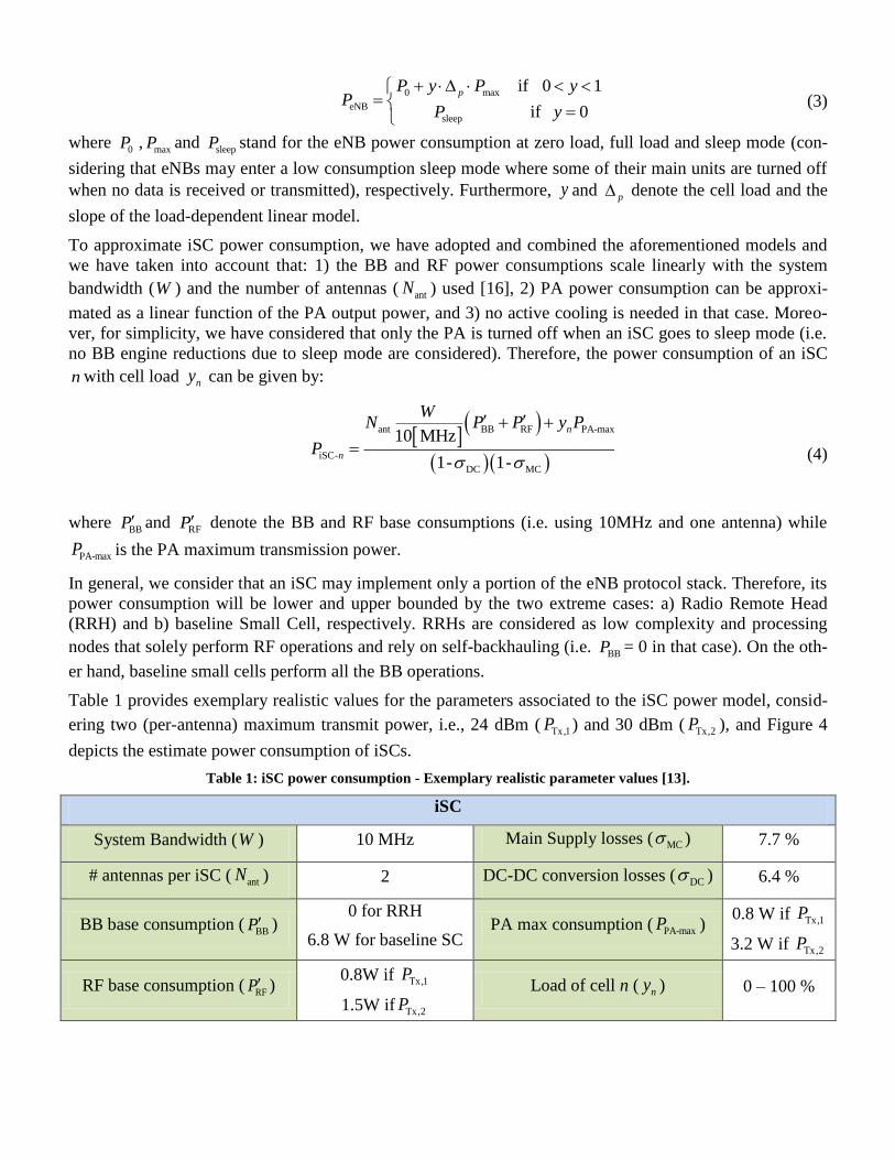
Table 1 provides exemplary realistic values for the parameters associated to the iSC power model, consid-
ering two (per-antenna) maximum transmit power, i.e., 24 dBm ( Tx,1P ) and 30 dBm ( Tx,2P ), and Figure 4
depicts the estimate power consumption of iSCs.
Table 1: iSC power consumption - Exemplary realistic parameter values [13].
iSC
System Bandwidth (W ) 10 MHz Main Supply losses ( MC ) 7.7 %
# antennas per iSC ( antN ) 2 DC-DC conversion losses ( DC ) 6.4 %
BB base consumption (BBP )
0 for RRH
6.8 W for baseline SC PA max consumption ( PA-maxP )
0.8 W if Tx,1P
3.2 W if Tx,2P
RF base consumption (RFP )
0.8W if Tx,1P
1.5W if Tx,2P Load of cell n ( ny ) 0 – 100 %

Figure 4: Complete small cell and RRH power consumption with respect to different RF output power and constraints.
B. RANaaS Platform Power Consumption
In order to obtain an accurate estimation on the power consumption of the RANaaS platform due to BB
processing2 moved from iSCs, we make use of the commodity hardware consumption coming from the IT
world; Fit4Green has investigated the power consumption for IT resources of data centres [17]. In particu-
lar, results for the various computing style servers are provided using a monitoring tool and a generic pow-
er consumption prediction model. Considering the measurements results for the cloud computing testbed
hardware equipment as the closest paradigm for the BBUs at a RANaaS platform, it can be observed that a
linear model can approximate well a server’s power consumption ( srvP ) versus its percentage CPU usage (
srvx %).
srv srv srv
srv 0 max srvpP P P x
(5)
where srv
0P and srv
maxP denote the power consumption of the server when in idle mode and maximum usage,
respectively, while srv
p stands for the slope of the equivalent linear power model which depends on the
specific server considered.
Considering the RANaaS BBU as an enclosure hosting several identical interconnected ISS Blade servers
(each considered as a set of multiple processors) equally sharing the requested workload, the servers’ pro-
cessing capacity (CapX ), in Giga-Operations-per-Second
3 (GOPS), will define the total number of servers (
srv N ) required to process the system BB-related workload ( X in GOPS) moved to RANaaS BBU, i.e.:
server
Cap
X
NX
(6)
and the percentage CPU usage at each server will be:
2 Note that for fair comparison, we consider as power consumption of the RANaaS platform only the extra power needed for computations due to BB pro-
cessing moved to RANaaS from iSCs (e.g at a RANaaS BBU). Other functionalities at RANaaS platform can be assumed that exist also at the core network of a
conventional system.
3 It is noted that the processing capacity of the server is usually expressed in GFLOPS [19]; however, it can be converted in GOPS, and in this work we use a 1:1 ratio as a conservative estimation.

server
Cap server
100%X
xX N
(7)
The question that arises next is how the extra RANaaS BBU workload can be related to cell load. In that
regard, the work in [16] considered the functionalities of various base station types and examined how the
GOPS per function block scale with cell load for a specific reference system. Targeting to a more general-
ized view, Werthman et al. defined recently the resource effort required to serve a UE at a specific time as a
function of the number of used antennas, the modulation bits, the code rate, the number of spatial MIMO-
layers and the number of allocated frequency/time resources each as allocated to the UE at that time [18].
Based on this work, we introduce an average sum to approximate the total extra RANaaS BBU workload
required to serve all UEs when an average BB % of BB processing is assumed to be moved towards
RANaaS platform from each iSC. To this end, the GOPS required at RANaaS platform will depend on the
total number of iSCs in the system, the load of each iSC, the system bandwidth, the number of antennas
used to serve a UE per iSC ( TxN ), the average number of data bits per symbol per user ( MSCe ) and the aver-
age number of MIMO layers per user ( MIMOe ):
iSC
2 MSCBBTx Tx MIMO
1
30 10 20100 10 MHz 6
N
n
n
eWX N N e y
(8)
Therefore, for any RANaaS BBU comprising servers with specific processing capacity, its overall power
consumption due to BB processing moved towards RANaaS platform will be the sum of the power con-
sumption at each of the required servers:
iSC
2 MSC
Tx Tx MIMO
srv srv srv
RANaaS 0 max
1Cap
Cap
Cap
30 10 2010 MHz 6
N
n p
n
eWN N e
X yP P y P
X X yX
X
(9)
To obtain an exemplary view on the power consumption of RANaaS platform we consider a cloud compu-
ting server comprising Intel Xeon E5540 processors as presented in [17] under the high efficiency configu-
ration policy (i.e. CPU frequency always set to maximum value). Table 2 introduces the respective realistic
values and Figure 5 illustrates the power consumption of this specific RANaaS BBU with respect to the
small cell RF output power for different BB shift.
Table 2: RANaaS platform power consumption - Exemplary realistic parameter values.
RANaaS platform
Server Capacity (CapX ) 324 GFLOPS [19]
Server idle consumption ( srv
0P ) 120 W Consumption at Server Max
Workload ( srv
maxP ) 215 W
Linear model slope (srv
p ) 0.44 # iSCs in cluster ( iSCN ) 10
Average # of antennas used to
serve a UE ( TxN ) 2
% of BB processing moved into
RANaaS from each iSC ( BB ) 10 | 50 | 100 %
Average # of data bits per symbol
per UE ( MCSe ) 4/3
Average # of spatial MIMO lay-
ers used per UE ( MIMOe ) 1.1
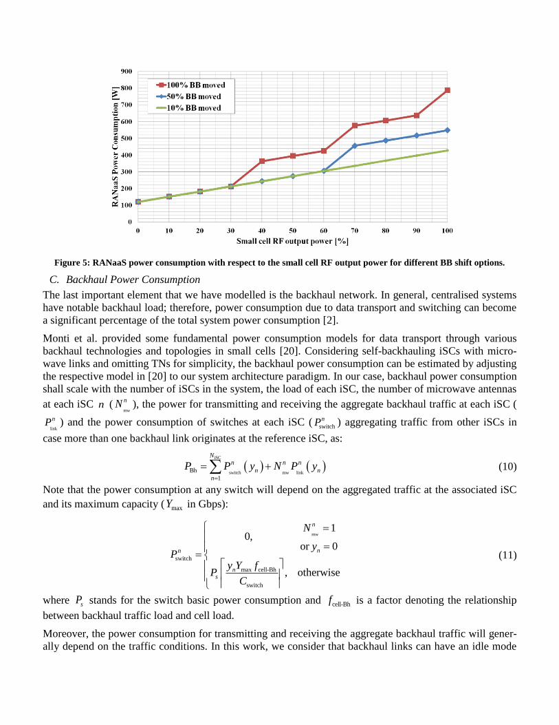
Figure 5: RANaaS power consumption with respect to the small cell RF output power for different BB shift options.
C. Backhaul Power Consumption
The last important element that we have modelled is the backhaul network. In general, centralised systems
have notable backhaul load; therefore, power consumption due to data transport and switching can become
a significant percentage of the total system power consumption [2].
Monti et al. provided some fundamental power consumption models for data transport through various
backhaul technologies and topologies in small cells [20]. Considering self-backhauling iSCs with micro-
wave links and omitting TNs for simplicity, the backhaul power consumption can be estimated by adjusting
the respective model in [20] to our system architecture paradigm. In our case, backhaul power consumption
shall scale with the number of iSCs in the system, the load of each iSC, the number of microwave antennas
at each iSC n (mw
nN ), the power for transmitting and receiving the aggregate backhaul traffic at each iSC (
link
nP ) and the power consumption of switches at each iSC (switch
nP ) aggregating traffic from other iSCs in
case more than one backhaul link originates at the reference iSC, as:
iSC
switch mw linkBh
1
Nn n n
n n
n
P P y N P y
(10)
Note that the power consumption at any switch will depend on the aggregated traffic at the associated iSC
and its maximum capacity ( maxY in Gbps):
mw
switch
max cell-Bh
switch
10,
or 0
, otherwise
n
nn
ns
N
yP
y Y fP
C
(11)
where sP stands for the switch basic power consumption and cell-Bhf is a factor denoting the relationship
between backhaul traffic load and cell load.
Moreover, the power consumption for transmitting and receiving the aggregate backhaul traffic will gener-
ally depend on the traffic conditions. In this work, we consider that backhaul links can have an idle mode

(i.e. when no data needs to be transported through backhaul) and a two-step function (low/high capacity
traffic), where the two capacity regions are distinguished by a single threshold ( thrC ):
link
idle
thrlow-traffic
max cell-Bh
thrhigh-traffic
max cell-Bh
, 0
, 0<
,
n
n
n
n
P y
CP P y
Y f
CP y
Y f
(12)
Table 3 presents the backhaul relevant parameters with exemplary realistic values. Note that backhaul traf-
fic load is translated into cell load considering current LTE-based RAN. For this, we consider the iSC max-
imum bits-per-second capacity (evaluated assuming a single carrier with 10MHz bandwidth, 2x2 MIMO,
64QAM, and 28% control overhead) and the non-negligible overheads from X2 U- and C-plane (~4%), the
transport protocol (~10%), and the IPsec (~14%) [21]. Finally, Figure 6 depicts the estimate backhaul pow-
er consumption where we can see that for generic small cells, the backhaul always operates in low capacity
region, which results in flat power consumption for medium/high cell RF output power.
Table 3: Backhauling Network power consumption - Exemplary realistic parameter values.
Backhauling Network
# microwave antennas per iSC ( mwN ) 2 Switch maximum capacity ( switchC ) 36 Gbps
Switch basic consumption ( sP ) 53 W Average cell capacity ( maxY ) 86.4 Mbps
Cell load to backhaul traffic factor ( cell-Bhf ) 128 % Traffic threshold between low/high
power regions ( thrC ) 500 Mbps
Node power region for idle/low/high traf-
fic conditions (idle/low/high-trafficP ) 22.2 / 37 / 92.5 W
Figure 6: Backhauling Network Power consumption with respect to the small cell RF output power.

V. RANAAS-BASED OPTIMAL CONTROLLER FOR ENERGY EFFICIENT SMALL CELLS
In this section, the proposed power model is used to evaluate a mechanism that manages the activity of NiSC
iSCs according to access characteristics and the Quality of Service (QoS). We consider that part of the
small cell functionalities, i.e. the Radio Resource Control, is shifted to the RANaaS. Accordingly, the
RANaaS manages the activity of the iSCs to match available resources and required services.
Markov decision process is used to model this optimization problem [22]. In the considered scenario, the
RANaaS receives data from the core network and stores it in a dedicated buffer. When required, RANaaS
activates a given iSC through the backhaul and forwards the associated data to it. Thereafter, the iSC will
autonomously manage available resources to transmit received data according to a first-in-first-out policy.
When a given iSC is idle, energy saving is realised due to the reduced running functionalities at the small
cell and at the backhaul network. On the contrary, as described in Section IV, when an iSC is activated, its
contribution to the energy consumption of the RAN (that includes the backhaul) depends on its load, i.e.,
the transmitted data on the backhaul and access resources. Finally, when an iSC is deactivated, basic cover-
age and synchronization is provided to the nearby users by the macro cell through dual connectivity [23].
Accordingly, the iSCs can rely on new carrier type, which avoids systematic activation to broadcast cell-
specific reference signals [23]. In this case, deploying the RANaaS at the macro cell site may enable to
manage the status of a limited number of neighboring ISCs, which seems to be the optimal choice in terms
of complexity and overhead.
In our model, the RANaaS is equipped with NiSC buffers of size M packets, each one dedicated to an iSC.
The number of packets received at an iSC at time step t (ft) is finite and depends on its load. Moreover,
when activated, an iSC i transmits at most Ri packets, according to the available bandwidth and the trans-
mission spectral efficiency.
Let S be a set describing the network state space and defined as S = Q × R × F, where Q, R, and F are the
composite spaces modelling the buffer, the data rate and the incoming traffic, respectively. At each time
step, the RANaaS observes the current state of the network st ∈ S and selects an action from the action
space A, where each action corresponds to activating at most one iSC and keep the others idle. The decided
action changes the current status from st to st+1, with a state transition probability T(st+1 | st; at), and incurs
in a cost Ct = C(st, at). Our goal is to find an optimal policy π that associates an action at(st | π) to the state
st. This policy aims to minimize the energy consumption and satisfying the QoS constraints while avoiding
concurrent access of multiple iSCs. This problem can be represented as follows:
a set of states S;
a set of actions A;
a state transition probability T;
a cost function C.
The statistics of the data rate and the incoming traffic are modelled as Markov chains, independent of the
time steps, buffer state and actions. Hence, the model is Markovian because the state transition depends
only on the current status/actions and is independent of any previous states/actions. Furthermore, we can
define the system cost function as:
),(~
),(~
ttttt asdasPC ,
(13)
where α is a weighting factor that prioritizes between EE and QoS while ),(~
tt asP and ),(~
tt asd denote the
sum of the NiSC length vectors indicating the power consumption at iSCs and packet losses, respectively.
Eq. (13) models the trade-off between the packet loss and the power consumption; to limit packet drop the
RANaaS should keep the iSCs activated and transmit packets stored in its buffer. On the contrary, minimiz-
ing power consumption requires to keep iSCs idle, which in turn may lead to packet loss.

To provide performance evaluation, we consider a hotspot composed by four iSCs (NiSC = 4) coordinated
by the nearby RANaaS. Without loss of generality, we consider that in a transmission time interval (set
equal to 1ms), at most one packet is received at each buffer and that an activated iSC can transmit up to two
packets. Packet length is considered equal to 1Kbits. The model presented in Section IV is used to compute
the network power consumption, due to the RANaaS platform, the backhaul and the iSCs. Accordingly, we
assume that iSC and backhaul equipment in idle mode consumes the 60% of its zero-load power. Moreo-
ver, we consider that 5% of the BB load is transferred by the iSCs to the RANaaS to manage their activa-
tion/deactivation.
Figure 7 shows the performance of the optimal stationary solution (obtained through value iteration [22])
with respect to a random policy and greedy approach. By using the random policy, at each time step, the
RANaaS randomly decides whether to keep iSCs idle or activated; on the contrary, when using the greedy
method, action is taken to minimize the instantaneous cost, i.e., without considering the total (over time)
expected cost. Solid, dotted and dashed lines, respectively, correspond to the optimal, greedy and random
solutions. Performance is presented in terms of cumulative network EE [bit/J] computed as the ratio of the
cumulative number of transmitted bits and the associated network power consumption measured over 1
second.
Figure 7: Cumulative Network EE with respect to different small cell management schemes.
The optimal solution leads up to 96% of gain with respect to the greedy solution; however, it gains only
16.4% with respect to the random policy. This surprising result is due to the limited energy consumption
associated with the random solution, which in turns results in an unacceptable number of dropped data.
VI. CONCLUSIONS
This article discusses EE aspects and related benefits of RANaaS implementation (using commodity hard-
ware) as evolution of LTE-Advanced networks toward 5G infrastructure. In fact, in the view of future defi-
nition of 5G systems, this cloud-based design is an important architectural solution, especially in terms of
efficient usage of network resources. After providing a vision of the advantages of RANaaS and its benefits
in terms of EE, we presented a consistent power model as a useful reference for further evaluations of flex-
ible centralization of RAN functionalities in terms of EE. The incremental benefits through the years have
been also discussed in perspective, by considering technological evolution of IT platforms and the increas-
ing matching between their capabilities and the need for progressive virtualization of RAN functionalities.
The description is finally complemented by an exemplary evaluation, in terms of EE, of a small cell activity
controller based on the RANaaS paradigm, as a promising technology for future sustainable 5G radio.
VII. ACKNOWLEDGEMENT
The research leading to these results has received funding from the European Community's Seventh
Framework Program FP7/2007-2013 under grant agreement n° 317941 – project iJOIN. The European Un-
ion and its agencies are not liable or otherwise responsible for the contents of this document; its content
reflects the view of its authors only. We gratefully recognize the great contributions of many colleagues
from iJOIN, who in fruitful cooperation, contributed with valuable insight, surveys and vision.
VIII. REFERENCES
[1] European Commission, Code of Conduct on Energy Consumption of Broadband Equipment, Version
5.0, Dec. 2013
[2] A. De Domenico, E. Calvanese Strinati, A. Capone, “Enabling Green cellular networks: A survey and
outlook”, Computer Communications, vol. 37, pp. 5-24, January 2014.
[3] 3GPP, Radio Access Network Technical Specification Group, TR 36.927, “Potential solutions for en-
ergy saving for E-UTRAN (Release 11),” September 2012.
[4] 3GPP, Radio Access Network Technical Specification Group, TR 25.927, “Solutions for energy saving
within UTRA Node B (Release 11),” September 2012.
[5] 3GPP, Technical Specification Group Services and System Aspects, TS 32.551, “Telecommunication
management; Energy Saving Management (ESM); Concepts and requirements (Release 11),” June
2013.
[6] GreenTouch, Green Meter Research Study: Reducing the Net Energy Consumption in Communication
networks by up to 90% by 2020, June 2013.
[7] I. Chih-Lin, C. Rowell, H. Shuangfeng, X. Zhikun, P. Zhengang, “Towards Green and Soft: A 5G Per-
spective”, IEEE Communication Magazine, vol.52, no.2, pp.66, 73, February 2014.
[8] K. Sundaresan, M. Y. Arslan, S. Singh, S; Rangarajan, and S. V. Krishnamurthy, “FluidNet: a flexible
cloud-based radio access network for small cells.” Proceedings of the 19th annual international confer-
ence on Mobile computing & networking (MobiCom '13), pp. 99-110, September 2013.
[9] P. Rost, C.J. Bernardos, A. De Domenico, M. Di Girolamo, M. Lalam, A. Maeder, D. Sabella, and D.
Wübben, “Cloud Technologies for Flexible 5G Radio Access Networks,” IEEE Communications Mag-
azine, vol.52, no.5, pp.68-76, May 2014.
[10] 3GPP, Radio Access Network Technical Specification Group, TS 36.300, “Evolved Universal Terres-
trial Radio Access (E-UTRA) and Evolved Universal Terrestrial Radio Access Network (E-UTRAN);
Overall description; (Release 11),” September 2014.
[11] National Industry of Standards and Technologies, “Cloud Computing Synopsis and Recommenda-
tions”, Special Publication 800-146, May 2012.
[12] HP Moonshot system, [online document, accessed April 2014]
http://h17007.www1.hp.com/us/en/enterprise/servers/products/moonshot.

[13] EARTH project, “D2.3 - Energy efficiency analysis of the reference systems, areas of improvements
and target breakdown,” https://www.ict-earth.eu/publications/publications.html
[14] G. Auer, V. Giannini, I. Godor, P. Skillermark,M. Olsson, M. Imran, D. Sabella, M. Gonzalez, C.
Desset, O. Blume, A. Fehske, “How much energy is needed to run a wireless network?,” IEEE Com-
munications Magazine, vol.18, no.5, pp.40-49, October 2011.
[15] Holtkamp, H.; Auer, G.; Giannini, V.; Haas, H., "A Parameterized Base Station Power Model," IEEE
Communications Letters, vol.17, no.11, pp.2033,2035, November 2013
[16] C. Desset, B. Debaillie, V. Giannini, A. Fehske, G. Auer, H. Holtkamp, W. Wajda, D. Sabella, F. Rich-
ter, M.J. Gonzalez, H. Klessig, I. Godor, M. Olsson, M.A. Imran, A. Ambrosy, O. Blume, "Flexible
power modeling of LTE base stations," IEEE Wireless Communications and Networking Conference
(WCNC), pp.2858-2862, 1-4 April 2012.
[17] ICT FP7 FIT4GREEN, Project Deliverable D3.3, “Presentation of the full-featured federated energy-
consumption models,” March 2012.
www.fit4green.eu/sites/default/files/attachments/documents/D3.3_final.pdf
[18] T. Werthmann, H, Grob-Lipski, and P. Proebster, “Multiplexing gains achieved in pools of baseband
computation units in 4G cellular networks,” Proceedings of the IEEE 24th International Symposium on
Personal Indoor and Mobile Radio Communications (PIMRC), September 2013.
[19] Intel Xeon Processor 5500 Series, [online document, accessed April 2014]
http://download.intel.com/support/processors/xeon/sb/xeon_5500.pdf
[20] P. Monti, S. Tombaz, L. Wosinska, and J. Zander, "Mobile backhaul in heterogeneous network de-
ployments: Technology options and power consumption," 14th International Conference on Transpar-
ent Optical Networks (ICTON), pp.1-7, 2-5 July 2012.
[21] NGMN Alliance, "Small cell backhaul requirements," White Paper, June 2012.
[22] R. S. Sutton and A. G. Barto, “Reinforcement learning: An introduction,” Cambridge Univ. Press,
1998.
[23] C. Hoymann, D. Larsson, H. Koorapaty, and C. Jung-Fu, "A Lean Carrier for LTE," IEEE Communi-
cations Magazine, vol.51, no.2, pp.74-80, February 2013.