energy efficiency best practice in housing installing ... · pdf fileenergy efficiency best...
TRANSCRIPT

• Systems from 500W to 25kW capacity
• Best Practice guidance on system design and installation
• Direct-connected, battery and grid-connected systems
Guidance for installers and specifiers
Energy Efficiency Best Practice in Housing
Installing small wind-powered electricity generating systems

Installing small wind-powered electricity generating systems
Contents
1. Small wind-power systems 3
2. System siting and sizing 4
3. System design 63.1 Wind turbine, tower and foundations 63.2 Direct-connected systems 93.3 Battery systems 93.4 Grid-connected systems 11
4. Safe siting and working 13
5. Commissioning and testing 14
6. Documentation 15
Appendix A 16System siting and sizing: customer information checklist
Appendix B 16Installation and commissioning: inspection checklist
Appendix C 19Electrical installation certificate
Appendix D 21G83/1: Installation commissioning certification form
Further reading 23
2
Note:This guide outlines industry Best Practice.There are,however, a number of mandatory obligations in this area.Text printed in blue, therefore, refers to mandatory and/orwidely recognised standards.

Installing small wind-powered electricity generating systems
1. Small wind-power systemsThis guide aims to provide system designers and installers withsufficient information to ensure that small wind energy systemscomply with current UK standards and with industry BestPractice. 'Small' in this context means between about 500W and25kW output, though most parts of this guide also apply tosystems of other sizes.
There has been little previously published on this topic and thisdocument includes new requirements - based on extensiveconsultation with industry and a review of Best Practice - thatare not set down in any other source.The guide also makesextensive reference to the many UK standards (such as the CEmark) which apply to this type of equipment.
Ensuring safetyThe long term safety of the wind turbine depends on a numberof issues that both designer and installer must address. Potentialhazards need to be identified and systematically eliminated orminimised.This does not just include those which may be presentduring installation but also any that may develop over time.This guidance document is divided into a number of sections.Sections 2 and 3 cover issues that need to be addressed duringthe design phase of the project. Many of these will have animpact on the installation process, which is the focus of the latersections.These deal in particular with safety aspects of theinstallation.
3
System design: long term safety cannot be achieved unless boththe system as a whole and each component individually arecorrectly designed and specified.The design process must includea consideration of normal and faulted operating conditions.
Safe working: poor installation can compromise the long termsafety of the system. Equally, unsafe site and working conditionscan put installation engineers at risk. Correct design of thesystem as well as thorough planning of the installation phase willhelp to ensure the quality of the installation as well as the safetyof the work team.
Installers need to take note of their statutory duties under healthand safety law and while this guide covers the key issues it makesno claim to be exhaustive. Installers are responsible for ensuringcompliance with the law.
The Construction (Design and Management) Regulations mayalso apply if more than four people will be involved in theconstruction work at any one time.The project is notifiable tothe Health & Safety Executive if it will exceed 30 days or involvemore than 500 person-days of work. However, there areexceptions to this.
Commissioning and testing:A comprehensive post-installationsystem inspection and testing regime will also be required if longterm performance and system safety are to be guaranteed.

2. System siting and sizingThis guide is primarily concerned with the installation of smallwind energy systems. However, a number of design-related issues,including the siting of the turbine and its size, will impact on itsperformance and are also likely to affect the installation process.
Keeping the customer informed
It is essential that the customer understands - or at leastappreciates - all the substantive issues involved and theirconsequences. Customer satisfaction depends to animportant extent on good communication. In particular,expected output and performance need to be carefullyexplained. Otherwise the customer could believe the systemto be operating below normal and require remedial work,when none is necessary! The customer also needs to bemade aware of factors, such as turbulence and obstructions,that may limit the available wind speed and hence the poweroutput.
If the customer is fully involved with the installation process,they will be able to support the project in communicationswith the local planning authority and the local community.
The checklist detailed in Appendix A covers most of therelevant issues and it should be completed together with thecustomer.
Planning permissionThe height and location of the wind turbine will affect whetherplanning permission is needed; in general, those with rotordiameters of more than two metres will require consent. If it isto be used purely for agricultural purposes on agricultural land,there may be a farming general consent covering the installation;however, the local planning office should still be contacted.
The planning authority may impose restrictions on the siting of awind turbine.These are normally for two reasons:• expected noise output• visual impact on the landscape
The customer should be made aware of any restrictions thatmight occur.
In assembling information for the local planning authority, thelatest planning guidance and recommendations should be takeninto account.
In support of a planning application, installers should:• advise customers to make contact with the local planning
authority themselves• urge customers to communicate with neighbours and the local
community about the project at an early stage• provide information to the authority on similar installations
(location, equipment type, etc)• provide appropriate drawings (electrical schematics for
example)• provide information on noise levels
Noise levels
Noise from small wind turbines can be categorised in twoways:• aerodynamic noise from the rotating blades• mechanical noise from the generatorWhether the noise is intrusive or not will depend on thelevel of extraneous background sound.Turbine noiseincreases with operating duty, but background noise is alsolikely to increase with stronger winds. In building-mountedturbines, mechanical vibrations may be transmitted throughthe structure and this may be experienced as audible noise.
Performance and outputThe power available from the wind is related to the cube of thespeed. In practice, this means that a 20% increase in windstrength will almost double the power available. It is thereforevery important to maximise the incident wind on the turbineblades.Wind speed increases with height and even smallincreases in turbine height can produce significant improvementsin performance.
The power available is also related to the square of the turbinerotor diameter. Increasing the diameter by 20% increases theavailable power by 44% for example.
Available power is proportional to the density of the air.Weatherconditions and height above sea level will therefore affect output.This effect is, however, very small in comparison with the othertwo.
Wind speedThe first step is to assess the likely annual average wind speed.The Department of Trade & Industry (DTI) has modelled windspeeds for every square kilometre of the UK (the NOABLmodel).Although small turbines require much lower averagespeeds than large machines, the project's technical and economicviability will need to be carefully examined if the annual averagespeed is less than 4.5m/s.
The DTI figures will only provide an initial estimate, astopological features such as terrain, trees and buildingssignificantly affect wind strength over a given site.
4
Installing small wind-powered electricity generating systems

5
Furthermore, two sites with the same annual average windspeeds may not produce the same amount of energy.Windstrength varies with the seasons, from day to day and even withtime of day. So the wind speed distribution - that is to say,frequency and duration of different wind strengths - will affectoutput.The site with the greater range, i.e. more high speedsmatched by lower speeds over the course of the year, will in factgenerate more energy because of the cubic relationship betweenwind speed and power.
For small scale projects, the use of anemometers and dataloggers to measure wind speeds over the course of a year israrely cost-effective.
Other considerationsWind direction: a turbine should be exposed to prevailing winds,i.e. the direction with the best overall combination of frequencyand strength. In most UK locations, the prevailing winds comefrom the south west.
Obstacles: wind speed increases with height as the ground andobjects close to it disrupt air flow.The 'roughness' of the groundis a measure of the way obstacles such as trees, buildings and thesurface topography act to effectively slow down the wind.
Turbulence: the flow of the wind is disrupted when it passes overor around objects, so a turbine should be sited to minimise theinfluence of obstacles (ideally from all directions). Excessiveturbulence may also cause fatigue and shorten a turbine's life.
Tower height: while greater height will increase energy output(higher wind speed and less turbulence, especially at sites ofgreater roughness), practical considerations such as cost and easeof lowering (for maintenance) also need to be taken intoaccount. See Figure 1.
Figure 1: Ideally, the turbine should be sited well clear of an obstacle.
System losses: losses from cables, batteries, conversion in aninverter, etc, will all result in a reduction of overall energy output.Such losses occur in any energy production process.
Practical issuesThe ideal site for a wind turbine is on a smooth, rounded andexposed hill-top or rise; one clear of any cliff faces and manymetres from obstructions such as trees and buildings.
In practice this very rarely happens.A wind turbine must bereasonably close to the point of energy use, or to an electricityconnection. Otherwise the cost of underground cabling mayprove excessive. Location may also be limited by factors such asland ownership.
The key point is to keep the turbine clear of large obstacles,particularly in the path of the prevailing wind.This should takeaccount of possible future obstructions such as tree growth.
Small wind turbines are sometimes mounted on buildings. In suchsituations, factors such as local turbulence, wind turbine type andstructural issues need to considered. In addition, the associatednoise and vibration levels will need to be taken into account,especially with regard to potential resonance that could beinduced within the structure of the building.
Installing small wind-powered electricity generating systems

3. System designFigure 2 shows diagrammatically the components of the varioussmall scale wind power systems considered in this guide and theorder in which they are discussed here.
Figure 2: System components
Installing small wind-powered electricity generating systems
3.1 Wind turbine, tower and foundationsThe requirements of this part apply to all installations, whethergrid-connected, battery or direct-connected systems.
Mechanical and structural requirements
Wind loadingThe UK has a good wind resource, but severe winds occuroccasionally.The turbine and tower must not become a healthand safety risk due to mechanical failure caused by high winds.
The wind turbine and tower should at least be rated towithstand wind speeds that average 35m/s (78mph) over a 10minute period without any damage to its operation.
The wind turbine and its support structure should be designedto survive a gust of at least 50m/s (112mph) without sufferingany damage that might result in any or all parts of the turbine ortower falling to the ground.
Gusts of 50m/s are rare, but they must not result in catastrophicmechanical or structural damage; although it is accepted thatsystems may not function correctly afterwards. Manufacturers'instructions will normally require turbine inspection followingsevere winds.Wind speeds of 35m/s are more common and it isimportant that the turbine is designed to return to normalreliable operation after such events (in accordance with BS EN 61400-2). Some particularly exposed sites, or installationsin public areas, may need to meet more stringent designrequirements.
Turbine support structures(a) GeneralThe support structure is commonly supplied by the turbinemanufacturer.This can be expected to be 'fit for purpose'.However, support structures from a third party will requiredetailed investigation, as well as consultation with the turbinemanufacturers in regard to compatibility and suitability as follows:• the support structure should be suitable for the particular
turbine and shall be designed to prevent detrimental effectsarising from movement or vibration
• all parts of the tower shall be corrosion resistant (e.g. madefrom galvanised or stainless steel)
• fixings must not loosen with vibration (use nylock bolts, forexample)
• dissimilar materials must be isolated from each other toprevent electrolytic corrosion
• the design must ensure that any exposed moving parts are atleast three metres from any point where persons or livestockmay stand. it should also prevent unauthorised access
• towers should be designed in such a way as to preventclimbing by unauthorised persons (this is of particularrelevance to lattice constructions)
6
Tower earthFoundations
Turbine output cable
Turbine junction box
Turbine isolator
Turbine display
Part 2: Direct connectsystem
Turbine (directconnect)control unit
Circuitprotection
Load(s)
DumpLoad(s)
Turbine(battery)control unit
Fuse disconnect
Battery
Turbine (gridconnect)control unit
Inverter
Inverter AC isolator
Main AC isolator
Connection to AC mains
Part 3: Battery system Part 4: Grid connectionsystem
Pictoral guide to system components
and document layout
Part 1– Turbine, tower and output system

7
(b) Foundations and anchor pointsConcrete foundations must be made according to BS 8004Foundations and BS 8110-1 Structural Use of Concrete - Part 1:Code of practice for design and construction. Key considerationsinclude:• the appropriate type and strength of concrete must be
specified to suit site conditions and foundation requirements.These specifications are to be provided to the installer in thefoundation instructions
• where steel reinforcement is incorporated, the requirements(including concrete cover at the edges) shall be provided in thefoundation instructions
• foundations and anchor points shall be proportioned to suitlocal ground conditions
• foundations and anchor points shall be designed in such as away as to prevent water pooling around the tower base or theanchors
• concrete must be thoroughly compacted with a vibrator orother means
• concrete must be worked around all parts and into all cornersand voids.
N.B. Details of the foundation/anchor design - including size,ground conditions, etc - are to be included in documentation todemonstrate that the turbine support system can withstand thestructural forces resulting from a 50m/s wind (see above).
(c) GuysAll shackles, turnbuckles, etc, shall be provided with the means toprevent loosening.
Figure 3:A shackle prevented from loosening.
Electrical requirements
Voltage and current - maximum valuesIn order to specify any part of the turbine electrical system, it isessential to know the maximum voltage and current output thatcan be expected - under normal or faulted operating conditions,and across the range of wind speeds it may encounter.
Different turbine designs vary in their response to normal andfaulted operating conditions. Some designs may stall when theturbine is short-circuited, but not all. Factors such as generatordesign, magnet type, furling mechanism, etc, will all have an influenceon the output current and voltage at different wind speeds andunder different operating conditions.
It is important to note that the exact conditions under which themaximum voltage or current occurs are not important - the valueis the key figure and must be known by the system engineer.
The following information should therefore be clearly stated inthe turbine documentation supplied by the manufacturer orsupplier:
V(max) - the maximum open circuit voltage that would begenerated by the wind turbine at wind speeds between 0-50m/s.
I(max) - the worst case, maximum steady-state current (eitherduring normal operation or into a short circuit) that would begenerated by the turbine at wind speeds between 0-50m/s.
Turbine output cablesA turbine output cable must be able to withstand theenvironmental conditions, as well as the voltage and current, atwhich it has to operate. It must be rated to suit theenvironmental conditions along its entire route i.e. it should beUV-stable, waterproof, armoured, etc.
The turbine output cable must be rated for at least V(max) and I(max)
(see above).This shall be calculated using standard correctionfactors for installation method, temperature, grouping andfrequency, in accordance with BS 7671. Sizing the cable in thisway ensures that the maximum potential fault current can besafely accommodated. Correctly sized cables will avoid the fireand safety risks associated with overloading.
In conventional systems, cables are protected by a fuse; thisrapidly clears a fault before it becomes a fire or safety risk.Witha wind turbine, however, the steady state fault current may beonly a little more - or sometimes less - than the maximumoperating current. In such cases, sizing a fuse to achievedisconnection under fault conditions is not possible. Instead,cable systems with suitable rating and protection are to beselected so as to minimise the risk of faults; Steel WireArmoured (SWA) cables may be used, or the cables enclosed inprotective conduit/trunking.
The turbine output cable should, in general, be sized so that thevoltage drop along it (at the rated output power of the turbine)is less than 4%. In some circumstances, a voltage drop greaterthan 4% may be justified on economic grounds.
Turbine isolatorA turbine isolator manually isolates the electrical output of theturbine.This will be necessary during system installation and alsofor maintenance and repair work.A manual brake on the turbineis not sufficient to guarantee supply isolation - brakes may slip oreven fail as the wind strengthens.
The turbine isolator must be a multi-pole device in order toelectrically isolate all the wires coming from the turbine.
The isolator must be rated for operation at the maximumvoltage and current of the turbine (see above).
N.B. Isolators need to be tailored to the machine. Open circuit,short circuit or dump load switching may be appropriate.
Installing small wind-powered electricity generating systems

Installing small wind-powered electricity generating systems
Anyone opening the isolator enclosure must be aware thatturbine output cables can become energised at any time - indeedthey often represent an additional energy source within a building.
The isolator enclosure should be clearly labelled “Danger,terminals may come live at any time”.The enclosure should bearthe label “Wind Turbine Isolator” with the ON and OFFpositions clearly marked.All labels must be clear, easily visible andshould be constructed and fixed so as to remain legible and inplace throughout the design life of the system.
Turbine junction boxA turbine junction box may be required where turbine outputcables are to be joined. It may also serve as a test point or apoint of secondary isolation.
The box must be labelled “Wind Turbine Junction Box - Danger,terminals may come live at any time”.All labels must be clear,easily visible and should be constructed and fixed so as to remainlegible and in place throughout the design life of the system.
N.B.The environmental and fault protection provisions in theturbine output circuit must be maintained in the make-up andconstruction of any junction box.
Tower earth(a) A turbine in proximity to existing lightning protectionWhere a turbine is to be mounted on a structure or buildingwith an existing lightning protection system (LPS), the installersof the LPS must be consulted so that the turbine can becorrectly incorporated into the protection system, checking thatno alterations to the LPS need to be made (changes to locationor to the height of the air terminations for example).
(b) A turbine within an equipotential zoneWhere a turbine is mounted within the equipotential zone of abuilding or other structure, the tower must be bonded to theinstallation's Main Earthing Terminal, in accordance with BS 7671.
Equipotential zone is defined in BS 7671 as: a zone in whichexposed-conductive parts and extraneous-conductive partsare maintained at substantially the same potential bybonding, such that, under fault conditions, the differences inpotential between simultaneously accessible exposed- andextraneous-conductive-parts will not cause electric shock.
(c) All other installationsThe following apply in all other cases:• the turbine tower is to be connected to a dedicated earth
electrode.An electrode resistance to earth not exceeding 10Ωshould be achieved, though may not be justifiable in some cases
• the earth electrode shall be placed as close as is practical tothe tower base and it must be installed in such a way as topermit periodic inspection. Periodic inspection is important asa failure of this earth termination may have a serious impacton the system, not least in the transmission of lightning surges
• the connection between the tower and the tower earth shouldbe made with copper cable (minimum CSA of 16mm2), taking adirect route and avoiding sharp bends
• separation between the turbine earth and building earth is tobe maintained.This is to ensure that any direct strikes on theturbine (which may be in a particularly exposed location) arenot coupled directly back to the building
Where steel wire armour is used for the turbine output cable,this should not intentionally or unintentionally be coupled to thetower earth and so bring the turbine earth inside the building.This could occur if a metal junction box is used to join cableswithin a steel turbine tower; the metal box would be coupled tothe armoured sheath by the SWA gland and also coupled to thetower by direct contact. In such a situation, a non-conductiveenclosure must be used.
Lightning protectionBS 6651 Code of practice for protection of structures againstlightning describes how to assess the likelihood of damage.Thismay be caused either by a direct strike or through surgesinduced in cables from a nearby strike.Tower earthing (seeabove) provides one element of protection.
(a) Dedicated Lightning Protection SystemsIf there is a risk of a direct strike, specialists should be consultedabout installing a separate LPS in accordance with BS 6651.
(b) Surge protectionCabling systems can be designed to provide a degree of surgeimmunity. The following measures will act to shield the cablesfrom inductive surges and attenuate surge transmission (byincreasing inductance):• turbine output cables should be as short as possible, bundled
together and not looped• long turbine output cables (for example, those over 50m)
should have an earth shield, which can be created by usingearthed, armoured cable or earthed metal conduit/trunking
Surge suppression devices will give additional protection:• where these are fitted to the turbine output cable, they should
be attached at the tower base. In the case of long cable runs,they should be fitted at both ends
• where surge suppression devices are fitted to protect specificequipment, they should be fitted as close as is practical to thedevice
• surge suppression devices must be electrically safe and poseno electrical fire hazard
MeteringAs a minimum, metering should be installed to displayinstantaneous power output and to record energy delivered bythe wind turbine system.The meter can be fitted at any point inthe system (e.g. it can record inverter output in grid-connectedsystems).
8

Installing small wind-powered electricity generating systems
9
Consideration should be given to placing the meter where theconsumer can read it. Not only will it add to customersatisfaction if the output can be viewed, but it should lead tomore effective fault detection.A spinning turbine is notnecessarily a working turbine and only metering can demonstratecorrect operation.
Metering the loads in a battery system should also beconsidered.
For grid-connected systems to receive payment on exportedelectricity / ROCs, the installation of an export meter may berequired, and this should be discussed with the nominatedelectricity supplier.
3.2 Direct-connected systemsIn a direct-connected system, the turbine output is connecteddirectly to the load.An example would be a wind heating system,where heater(s) run directly from the turbine as and when windenergy is available.
However, a typical direct-connected system will not usuallysupply the 240V, 50Hz sinusoidal AC for which most commonelectrical equipment is designed.All parts of such systemstherefore need to be specified to the voltage and currentmaxima (as well as frequency) that can be expected. Forexample, with DC systems, protection or switching devices mustbe rated for DC operation; and in high frequency systems,additional de-rating factors may need to be applied to multi-corecables.
Turbine direct-connect control unitThis provides the interface between the turbine and the load. Itmay provide voltage transformation, rectification and progressiveswitching of loads as wind speed increases. In addition, it mayincorporate other functions such as isolation or metering. Keyconsiderations include:• the control unit must be rated for the current and voltage
maxima (see Section 3.1, Electrical requirements) • it must be labelled “Supplied from wind turbine. Isolate at
turbine isolator before carrying out work. Isolator situated …………………………………………”
• if a control unit incorporates specific functions described inSection 3.1 such as isolation, the relevant requirements of thatsection must be applied
• for wind speeds up to 35m/s, the system must be designed insuch a way that no damage results to the control unit - or tothe turbine - if all the loads are temporarily disconnected
• for wind speeds up to 50m/s, the control unit must bedesigned to minimise the risk to itself or the system, from fireor shock
Circuit protectionConventional cable protection employs fuses to rapidly clear afault before it presents a fire or safety risk.With a direct connectwind turbine system two issues need to be addressed:
• the steady state fault current may be a little more (or less)than the maximum operating current - hence fault currentsmay not trip any circuit protection sized to meet the operatingcurrent
• there may be no Neutral-Earth bond at the supply.Withoutsuch a link, a fault to earth cannot result in an earth faultcurrent and subsequent tripping of circuit protection
A system designer needs to identify and implement a suitableprotection method for direct connected circuits. Measures will varyfrom system to system depending upon the system voltage, turbineand load type.The designer, referring to BS 7671, needs to be clearas to the type of system being created e.g.TN-S,TT, PELV, etc.
Circuit protection should be designed to BS 7671 and the circuitprotection devices (either fuses or MCBs) must be rated foroperation at the voltage, current and frequency as supplied fromthe control unit.
LoadsLoads should be rated for operation at the voltage, current andfrequency supplied from the turbine control unit. Circuitprotection will be needed where loads and/or cabling are ratedat less then the full turbine output (such as a system where ten1kW heaters are run from a single 10kW turbine).
Labelling/signageWhere a wind turbine provides an additional source of supplywithin a building, circuit protection devices, loads and all points ofisolation shall be labelled “Supplied from wind turbine. Isolate atturbine isolator before carrying out work. Isolator situated …………………………………………”
A circuit diagram marked with the contact telephone number forthe supplier/installer/maintainer of the equipment shall also bedisplayed.
All labels must be clear, easily visible and should be constructedand fixed so as to remain legible and in place throughout thedesign life of the system.
3.3 Battery systemsIn this guide, a battery system is one where the turbine charges,via a control unit, a battery bank.The design of any systemconnected to run loads from such a battery is outside the scopeof this document.
Turbine battery control unitThis provides the interface between the turbine and the battery. Itmay provide voltage transformation, rectification and batterycharge regulation.The unit may also function as a dump loadcontroller, activating loads once the battery is fully charged. Inaddition, it may incorporate other functions such as isolation ormetering. Key considerations include:

Installing small wind-powered electricity generating systems
• the control unit must be rated for the current and voltagemaxima (see Section 3.1, Electrical requirements)
• it must be labelled “Supplied from wind turbine. Isolate atturbine isolator before carrying out work. Isolator situated……………………………………………………”
• if a control unit incorporates specific functions described inSection 3.1 such as isolation, the relevant requirements of thatsection must be applied
• for wind speeds up to 50m/s, the control unit must bedesigned to minimise the risk to itself or the system, from fireor shock
Controller-battery cablesA full recharge is important for good battery health.A small sizecable between the control unit and the battery - with anassociated high voltage drop - may lead to the charge regulationcontrol system prematurely disconnecting the turbine towardsthe end of the charge cycle.
The cables should therefore be sized for a maximum voltagedrop of less than 1% at peak turbine output. For controllers witha separate battery sense function, a fused battery sense cable canbe installed.
Battery over-current productionSignificant amounts of energy are stored within a battery andthese have the capacity to deliver large fault currents. Properprotection must be provided. Key considerations include:• an over-current device must be installed in the positive wire
between the battery and the turbine controller.The length ofcable between the device and the main positive terminal onthe battery must be as short as practicable
• the over-current device (either a fuse or circuit-breaker) must:- be sized so as to have a trip value less than the lowest cablecurrent rating of:(i) the main turbine output cable (ii) cables within the turbine control unit, or (iii) the controller-to-battery cable.
• cable ratings are to be adjusted using standard correctionfactors for installation method, temperature, grouping andfrequency to BS 7671, and must:- be rated for operation at DC, at 125% of the nominal battery
voltage- have an interrupt rating greater than the potential battery
short circuit current
Battery disconnectionA means of manual isolation must be provided for the battery,either combined with the over-current device or as a separateunit.The length of the cable between it and the battery must beas short as practicable. Isolation is to be installed and the systemdesigned so that the turbine cannot directly feed the loads whenthe battery has been disconnected.
Battery selectionThere are various approaches to what has been described as the'black art' of battery selection, sizing and design. However, thereare some key considerations:• is the battery fit for purpose, i.e. appropriately rated for its
duties? In the majority of cases a true 'deep cycle' battery willbe required
• does it have an adequate storage capacity and cycle life?• is a sealed or vented battery more appropriate for the
particular installation?• will the battery be made up of series cells or parallel banks?
While series cells will generally give better performance,practical considerations may influence the design. In general,though, banks with more than four parallel units are to beavoided.
Battery sizingFor an effective charging regime where a wind generator is theonly charge source, the battery would normally be sized so thatthe output of the turbine falls between the manufacturer'smaximum and minimum recommended charge rates.
Charge/discharge rates (C) are commonly expressed as an hourlyrate derived from the formula:Rate = Capacity (Ah)
Time (h)For example, a C10 charge rate for a 500Ah battery would takeplace at 50A.
Charge rates between C5 and C20 are often used in systemswith vented lead acid batteries, for example.
Battery installationIn an enclosed location, ventilation must be provided to batteryinstallations with an air inlet at low level and an outlet at thehighest point in the room or enclosure.
Sufficient ventilation is needed to remove battery gases. It isparticularly important in the case of vented lead acid units ashydrogen is given off during charging - a concentration of morethan 4% creates an explosion hazard.Ventilation also preventsexcessive heat build up.
BS 6133 Safe operation of lead acid stationary batteries gives aprocedure for calculating ventilation requirements.
Battery banks must be housed in such a way that:• access can be restricted to authorised personnel• adequate containment is assured• appropriate temperature control can be maintainedBattery terminals are to be guarded so that accidental contactwith persons or objects is prevented.
10

Installing small wind-powered electricity generating systems
The ideal operating temperature for a lead acid battery is around25ºC; temperatures significantly above or below this will lead toreduced lifetime and capacity. Indeed, at very low temperatures,discharged batteries may freeze and burst, while at hightemperatures, thermal runaway can occur in sealed batteries.Items which could produce sparks (e.g. manual disconnects, relays)should not be positioned within a battery box or directly above one.
Battery gases are corrosive, so cables and other items inside abattery enclosure need to be corrosion resistant. Sensitive electronicdevices should not be mounted in, or above, a battery box.
To ensure proper load/charge sharing in a battery bank made upof units connected in parallel, the units need to have the samethermal environment and the same electrical connection resistance.
In larger battery banks, fusing each parallel unit should be considered.
Figure 4:A typical connection configuration for a small parallelbattery bank (take-offs are on opposite corners)
The following warning signs are to be displayed:• No Smoking or Naked Flames• Batteries contain acid - avoid contact with skin or eyesAll labels must be clear, easily visible and should be constructedand fixed so as to remain legible and in place throughout thedesign life of the system.
Protective equipment, including appropriate gloves and goggles -together with an eye wash and neutralising agent - should bestored adjacent to the battery installation.
Labelling/signageCircuit protection, and all points of isolation shall be labelledwith “Supplied from wind turbine. Isolate at turbine isolatorbefore carrying out work. Isolator situated: …….……….……….……….……….……….…”
A circuit diagram marked with the contact telephone number forthe supplier/installer/maintainer of the equipment shall also bedisplayed.
All labels must be clear, easily visible and should be constructedand fixed so as to remain legible and in place throughout thedesign life of the system.
3.4 Grid-connected systemsGrid-connected systems generate electricity which is synchronisedwith the public electricity supply. Before connecting to the grid,installers must get written approval from the local DistributionNetwork Operator (DNO).
Guidance on connecting a small scale embedded generator(SSEG) can be found in Engineering Recommendation G83/1Recommendations for the connection of small scale embeddedgenerators (up to 16A per phase) in parallel with public lowvoltage distribution networks. Larger systems are covered inEngineering Recommendation G59/1 Recommendation for theconnection of embedded generating plant to the regionalelectricity companies' distribution systems.
Systems are of two types:(a) AC generator, connected via dedicated synchronisation and
protection relays(b) inverter connected
(a) Systems using an AC generatorA wind turbine with an AC generator can be connected to thenetwork via synchronisation and protection control systems.These are not normally off-the-shelf or type-tested products.
Design, testing and commissioning of these systems needs to bedone in full consultation with the DNO and in the light of G83/1and G59/1.
The details of such systems are beyond the scope of thisdocument although many sections of this guide (such as isolationand labelling) will apply.
(b) Inverter-connected systemsThese commonly rely on a type-tested inverter and this providesthe DNO with a relatively straightforward way to assess thesystem's suitability for connection.While G83/1 does notspecifically set out details for wind power, the requirements forinverter-connected PV systems (G83/1 Annex C) are commonlyadopted for wind systems.
Turbine grid-connect control unitThis provides the interface between the turbine and the grid-connect inverter. It can provide voltage control as well asrectification. It may also incorporate other functions such asisolation and metering. Key considerations include:• the control unit must be rated for the current and voltage
maxima (see Section 3.1, Electrical requirements) • it must be labelled “Supplied from wind turbine. Isolate at
turbine isolator before carrying out work. Isolator situated………………………………………………”
• if a control unit incorporates specific functions described inSection 3.1 such as isolation, the relevant requirements of thatsection must be applied
11

Installing small wind-powered electricity generating systems
• for wind speeds up to 50m/s, the control unit must bedesigned to minimise the risk to itself or the system, from fireor shock
InvertersInverters must carry a current Engineering RecommendationG83/1 Type Test certificate and comply with all other parts ofG83/1, unless specifically agreed with an engineer who isemployed by and appointed by the DNO for this purpose.Thisagreement must also be in writing.
Where G83/1 applies, inverters must be programmed so that theautomatic protection system operates at:• operating voltage greater than 264V phase to neutral• operating voltage less than 207V phase to neutral• operating frequency greater than 50.5Hz• operating frequency less than 47Hz• loss of mains
The inverter must also be capable of withstanding the maximumvoltage and current output supplied by the turbine control unitfor winds up to 50m/s.
A key safety concern is that the wind system should disconnectwhen the distribution system is not energised.This is to preventthe danger of the wind system feeding the network or localdistribution system during a planned (or unscheduled) loss ofmains. Such an event is known as 'islanding' and presents apotential hazard to those working on the network ordistribution system.Type tests established by G83/1 ensure thatan inverter is properly protected against islanding.
Larger systemsG83/1 covers systems up to 16A per phase.Above this level, thesystem designer will need to consult the DNO in order todetermine the appropriate protection scheme.This may includean additional protection relay to the requirements of G59/1.However, G83/1 does give the DNO discretion to “use thisengineering recommendation if it is considered more appropriatethan G59/1”.
AC isolatorTwo AC switch disconnectors, in accordance with BS EN 60947-3 Specification for low-voltage switchgear andcontrol gear, switches, disconnectors, switch-disconnectors andfuse-combination units, must be provided between the inverterand the point of interconnection to the supply. One is to beinstalled adjacent to the inverter and the other next to the pointof interconnection. If they are to be in the same room, only thelatter is required.They must:• switch all live and neutral cables• clearly show ON and OFF positions and be labelled as “wind
system - point of emergency isolation”The disconnector adjacent to the point of interconnection mustalso be lockable - in the OFF position only - and it must bereadily accessible.
When connecting switching devices, the public supply is to beconsidered 'the source' and the wind installation 'the load'.
AC cablingThe inverter(s) must be connected, via a dedicated circuit, to aspare fuseway in the main distribution unit, or to a fuseway in anadditional dedicated distribution board.
AC cables are to be specified and installed in accordance with BS 7671.
When generating, the voltage at the inverter terminals is slightlyhigher than that at the distribution board.This voltage drop mustbe kept to a minimum so that the protection systems operatecorrectly.To do this, the AC cable between the two should beoversized in order to keep the voltage drop small - a 1% drop isacceptable.
AC fault current protectionThe short circuit current from an inverter is approximately equalto its full load current. Over-current protection devices cannottherefore distinguish between full load and fault conditions.Therefore short circuit protection is not feasible - or required -at the inverter output.
Short circuit protection for the dedicated feeder cable to theinverter(s) must be provided at the distribution board.Thiselectrical protection is to be specified and installed in accordancewith the requirements of BS 7671.
Labelling/signageLabelling must be provided at the service termination, meterposition and all isolation points in order to indicate the presenceof on-site generation and to show the position of the main ACswitch disconnector.A suitable design for the label is shown inFigure 5.
Figure 5: Example of sign showing the presence of on-sitegeneration and the location of the isolators.
At the interconnection point, the following is also to bedisplayed:• circuit diagram• summary of protection settings that have been incorporated in
the equipment• a contact telephone number for the
supplier/installer/maintainer of the equipment.All labels must be clear, easily visible and should be constructedand fixed so as to remain legible and in place throughout thedesign life of the system.
12

Installing small wind-powered electricity generating systems
13
4. Safe siting and working Safe sitingThe wind turbine should ideally be placed well clear of anybuildings, obstructions and places where the public may gather(see Section 2, Practical issues).
It is clearly not always possible to achieve the ideal location. Sothe additional risks and Health & Safety considerations must becarefully weighed. Some manufacturers do offer extra safetyfeatures to minimise the - already small - risk still further.
Regarding safe siting, anchors and guy cables for towers shouldbe well away from roads, tracks, footpaths, etc. If there islivestock on the site, then guyed towers, their cables and anchorsshould be protected by fencing.
Installation and operationHealth & Safety guidelines and conventional electrical installationpractices apply also to the installation of wind turbine systems.Issues such as working at height and standard domestic wiringare covered in other publications and are not dealt with here.The following comments highlight ways to mitigate the particularhazards associated with the installation of a wind turbine system.
As part of standard Health & Safety practice, a Risk Assessmentshould be completed.This is a legal requirement under theManagement of Health & Safety at Work Regulations 1999.
General issues• Due regard should be given to any public rights of way close
to the installation site• The local situation should be taken into account, e.g. the likely
presence of children• Existing site services (e.g. overhead or underground electric
cables) should be identified and exclusion zones defined• Temporary signs, notices and barriers should be erected• The local weather conditions should be considered• Turbines should be maintained according to the manufacturer's
requirements in order to minimise risk. It is recommendedthat maintenance is carried out by a suitably trained individualor individuals.Where turbines are located in public places, thecustomer should be encouraged to place the maintenance withrepresentatives of the manufacturer
Turbine and tower - structural and mechanical works• Structural and mechanical installation must be actively managed
and supervised by a suitably experienced and competent person• All workers involved in the works must be fully briefed on the
sequence of operations before they commence.This is toinclude the identification of danger areas that must not occupiedduring the erection process
• All personnel must wear appropriate personal protectiveequipment, including high visibility jackets, hard hat and safetyboots
• Anyone working at height must work to the requirements ofthe relevant statutory provisions, including the use of suitableaccess, fall prevention and fall arrest equipment
• During installation and maintenance works, an exclusion zoneshall be established to prevent persons not engaged witherection of the turbine from gaining admittance
• Standard precautions for working with rotating machineryshould be taken: long hair should be tied back; loose clothingavoided; rings, necklaces and other jewellery removed
Turbine electrical works• All work is to be undertaken by experienced, competent and
authorised personnel who are fully familiar with standardworking practices within the electrical industry and who areacquainted with the maximum voltages present on the systembeing installed
• The turbine must be verifiably and effectively braked. Liveworking practices are to be adopted during the initialconnection of the turbine to the main output cable (seeRegulations 4(4), 14 and 15 of the Electricity at WorkRegulations 1989 and also BS EN 6093 and BS EN 60900)
• Subsequently, the turbine isolator must be secured open for allother works on the electrical system. Relying solely on amechanical turbine brake to prevent against shock is notacceptable
Working with batteries• Appropriate personal protective equipment must be worn,
including gloves and goggles. Metal items such as rings andneck chains should be removed before commencing work.Aneye wash should be near to hand
• Tools for battery installation should be insulated and acidresistant. Spanners should be approved single-ended types
• Work on battery installations should be carried out in a pre-planned manner to minimise the number of conductorsexposed at any one time
• Batteries should be adequately vented during works and anysource of spark or open flame avoided.

Installing small wind-powered electricity generating systems
5. Commissioning and testingInspection and testing of the completed system must be carriedout to the requirements of BS 7671.
Accurate performance testing of a turbine is only possible wherean anemometer reading at the hub height is available. For mostsmall systems, such data will not be available. Readings from thesystem display meter will often be the only means to determinehow well the system is working.
Test and inspection certificates modelled on BS 7671 and tailoredspecifically for use with wind systems are included in this guideas Appendix C.An installation and commissioning inspectionchecklist for the whole installation is also included (see AppendixB).This, or a similar document prepared by the installer, shouldbe completed and a copy provided to the customer.
Grid-connected systemsDNO approval must be obtained in order to operate a grid-connected wind turbine. For smaller systems under 16A perphase, the process for notifying and gaining approval from theDNO can be found in G83/1.Though G83/1 does not specificallyaddress wind systems, the notification requirements cover allsmall scale embedded generation.
For single systems of less than 16A per phase, the installer mustinform the DNO on the day of connection and then provide fulldetails on an Installation Commissioning Confirmation form(G83/1 Appendix 3) within 30 days. See Appendix D of this guide.
For larger systems, or sites where a number of turbines are tobe installed in close geographic proximity, prior notification ofthe DNO is necessary.
14

Installing small wind-powered electricity generating systems
Documentation referring specifically to the wind turbine willusually be produced by the wind turbine manufacturer.Theinstaller will make some additions - for example, the wiring andinterconnection diagram.
Additional, system-dependent documentation requirementsinclude:• V(max) and I(max) calculations (see Section 3.1 Electrical
requirements)• battery maintenance schedules (watering, equalisation, etc)• warranty information• noise levels (see Section 2)• design life of system parts• a maintenance record sheet
15
6. DocumentationThe following must be provided to the customer:(a) turbine support structure specifications - including, where
appropriate, an assessment of local ground conditions as wellas the installation requirements, specification of materials, etc
(b) drawings, specifications and instructions for assembly,installation and erection
(c) an operator's instruction manual(d) a maintenance manual
The following should be included in the operation, inspection andmaintenance documentation:(i) Installation• details of all loads, weights, lifting points, special tools and
procedures necessary for the handling, installation andoperation of the system
• requirements for cranes, hoists and lifting equipment (includingall slings, hooks and other apparatus) necessary for safe lifting
• checklist to confirm proper lubrication and pre-serviceconditioning of all components
• details of the manufacturer's recommended erectionprocedures
• identification of critical fasteners as well as details ofprocedures for confirming torque and other requirements
• a set of field assembly and installation drawings• minimum design requirements for the foundation and anchor
system • a complete wiring and interconnection diagram
(ii) Operation• details of safe operating limits• a description of start and shutdown procedures• procedures for functional checks on the protection subsystems• a description of the subsystems and their operation
(iii) Inspection and maintenance• maintenance and inspection cycles and procedures• a schedule prescribing frequency of lubrication and type of
lubricant or any other special fluid• procedures for unscheduled maintenance and emergencies• schedules for guy inspection and re-tensioning, bolt inspection
and torquing (including tension and torque loading details)• diagnostic procedures and a trouble-shooting guide
Installing small wind-powered electricity generating systems
16
Yes No
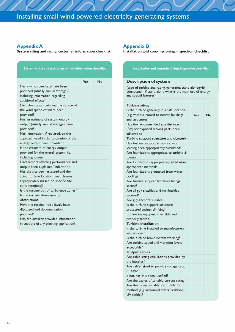
Appendix ASystem siting and sizing: customer information checklist
Appendix BInstallation and commissioning: inspection checklist
System siting and sizing: customer information checklist
YesHas a wind speed estimate beenprovided (usually annual average)including information regardingadditional effects?Has information detailing the source ofthe wind speed estimate beenprovided?Has an estimate of system energyoutput (usually annual average) beenprovided?Has information, if required, on theapproach used in the calculation of theenergy output been provided? Is the estimate of energy outputprovided for the overall system, i.e.including losses? Have factors affecting performance andoutput been explained/understood?Has the site been assessed and theactual turbine location been chosenappropriately (based on specific siteconsiderations)?Is the turbine out of turbulence zones?Is the turbine above nearbyobstructions?Have the turbine noise levels beendiscussed and documentationprovided?Has the installer provided informationin support of any planning application?
No
Installation and commissioning: inspection checklist
Description of system
Turbine sitingIs the turbine generally in a safe location?(e.g. without hazard to nearby buildingsand structures)Has the recommended safe distance(3m) for exposed moving parts beenadhered to? Turbine support structure and siteworkHas turbine support structure windloading been appropriately calculated?Are foundations appropriate to turbine &tower?Are foundations appropriately sized usingappropriate materials?Are foundations protected from waterpooling?Are turbine support structure fixingssecure?Are all guy shackles and turnbucklessecured?Are guy anchors suitable?Is the turbine support structureprotected against climbing?Is lowering equipment suitable andproperly stored?Turbine installationIs the turbine installed to manufacturers'instructions? Is the turbine brake system working?Are turbine speed and vibration levelsacceptable?Output cablesAre cable sizing calculations provided bythe installer?Are cables sized to provide voltage dropof <4%?If not, has this been justified?Are the cables of suitable current rating?Are the cables suitable for installationmethod (e.g. armoured, water resistant,UV stable)?
(type of turbine and rating, generator, stand alone/gridconnected - if stand alone what is the main use of energy,any special features)

Installing small wind-powered electricity generating systems
Appendix B (cont.)
Installation and commissioning: inspection checklist
YesAre the cables properly installed and fixedwith safe routeing (e.g. at sufficientdistance from heat sources and sharpsurfaces/edges)?Are turbine electrical connections soundand weatherproof?Turbine isolatorIs the isolator correctly rated?Is the isolator installed correctly and allelectrical connections secure?Are labels in place?Turbine junction box(es) if appropriateIs the junction box installed correctly andelectrical connections secure?Is the junction box in suitable location,appropriate boxing (IP rating should benoted on documentation)Are labels in place?Earthing and lightning protectionIs the turbine support structure earthcorrectly installed?Is lightning/surge protection correctlyinstalled, if required?Turbine meteringIs the metering system installed correctlyand are all electrical connections secure?Has the metering system been explainedto the customer?Turbine controllerIs the control unit suitably rated forcurrent and voltage?Is the controller installed correctly and allelectrical connections secure?Is the controller in a suitable location,with appropriate boxing (IP rating shouldbe noted on documentation)?Is any controller requiring heat dissipationsuitably ventilated and mountedappropriately?Are appropriate labels in place?DocumentationHas an Operation & Maintenance manualbeen supplied including problemdiagnostics, contact details, maintenanceschedule/record sheet, etc?
No
Installation and commissioning: inspection checklist
YesHas an Operation & Maintenance manualbeen supplied including (where relevant)documented procedures for stoppingturbine and lowering tower safely,battery maintenance?Have manuals for all specific equipmentbeen passed to the customer (includingcontroller, inverter, etc, as appropriate)Has all warranty information beenpassed to the customer, including systemand all parts i.e. turbine, wiring,inverter/batteries?Has information on the system designbeen supplied to the customer, e.g.V(max), I(max), noise levels, electricalschematics and site layout / civil worksdrawings, design life of system parts?Has the installation certificate & testsheet (BS 7671) been supplied (asappropriate)? Grid-connected systems only: Has signedapproval from DNO been passed to thecustomer?Grid-connected systems only: Has a printout of protection settings been supplied?
Direct-connected systems General design
Is the load suitable for intermittentoperation and direct connection?Are the turbine voltage and currentmaxima within load limits?Is the controller suitable for application?InstallationAre the dump heaters suitably mountedto prevent fire/burns and installed withhigh temperature cables?Are suitable fuses/isolation installed?Labelling/signageAre loads, fuses and points of isolationlabelled?Are the system schematic and installer'scontact details displayed?Are all signs suitably fixed and durable?
No
17

Installing small wind-powered electricity generating systems
18
Installation and commissioning inspection checklist
Yes
Battery systemsGeneral designIs battery over-current protectionprovided within the design?Is manual isolation of the battery (batterydisconnect) provided within the design?Battery specificationHas the battery manufacturer beencontacted or their data reviewed forsystem recommended charge rates?InstallationIs battery isolation installed such thatturbine cannot directly feed the loadswhen the battery is disconnected?Is the battery in a secure, vented andappropriate location?Is the battery housed suitably andterminals protected?Are all the cables to the battery fused,with fuses as close as practicable to thebattery?Are battery fuses rated for DC?Is the fuse rating less than (de-rated)cable rating?No fuse in common between windturbine and DC load? (Where DC loadsused)Are inverter and controls suitablyhoused, mounted and ventilated?Are DC cables sized for safety andvoltage drop (particularly invertercables)?Are DC cables safely installed/routed?Is AC wiring to BS 7671?Is there an isolator between battery andcontroller/inverter?Are battery voltage and turbine outputmeters installed and visible?Are dump heaters suitably mounted toprevent fire/burns and installed with hightemperature cables?Labelling/signageAre battery installation labels present (nosmoking etc)?
No
Installation and commissioning inspection checklist
YesAre fuses and points of isolation labelled?Are the system schematic and installer'scontact details displayed?Are all signs suitably fixed and durable?
Grid-connected systemsGeneral designIs the inverter suitably sized?Does the inverter carry a currentEngineering Recommendation G83/1Type Test certificate or has agreementbeen reached, in writing, with DNO? InstallationIs the inverter suitably installed for heatdissipation?Is there a local AC isolator (double-pole)installed adjacent to the inverter?Is there a double-pole AC isolator(lockable in the off position only)installed adjacent to at the point ofinterconnection with the supply?Is AC cable suitably specified andinstalled in accordance with BS 7671 andsuitably sized (calculations provided byinstaller)? Is cabling suitably selected andsecured/routed?Is suitable AC fault current protectionprovided at the distribution board(specified and installed in accordancewith BS 7671)?Labelling/signageAre dual supply notices installed at theservice termination, meter position andall points of isolation? Is the point of AC isolation suitablylabelled?Is a system schematic displayed?Are protection settings and installer'scontact details displayed?Are all signs suitably fixed and durable?Has disconnection if grid fails beenchecked?
No
Appendix B (cont.)

Installing small wind-powered electricity generating systems
Appendix CThis certificate is courtesy of the Institution of Electrical Engineers and can be downloaded fromwww.iee.org/Publish/WireRegs/Forms_2004.pdf. Note: Only the certificate is shown here.A schedule of items inspected, together with aschedule of test results, are to be appended to this form.
19

Installing small wind-powered electricity generating systems
20
Appendix C (cont.)
Installing small wind-powered electricity generating systems
21
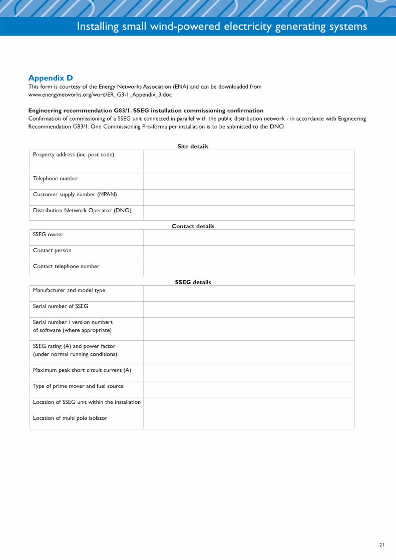
Site detailsProperty address (inc. post code)
Telephone number
Customer supply number (MPAN)
Distribution Network Operator (DNO)
Contact detailsSSEG owner
Contact person
Contact telephone number
SSEG detailsManufacturer and model type
Serial number of SSEG
Serial number / version numbers of software (where appropriate)
SSEG rating (A) and power factor(under normal running conditions)
Maximum peak short circuit current (A)
Type of prime mover and fuel source
Location of SSEG unit within the installation
Location of multi pole isolator
Appendix DThis form is courtesy of the Energy Networks Association (ENA) and can be downloaded from www.energynetworks.org/word/ER_G3-1_Appendix_3.doc
Engineering recommendation G83/1. SSEG installation commissioning confirmationConfirmation of commissioning of a SSEG unit connected in parallel with the public distribution network - in accordance with EngineeringRecommendation G83/1. One Commissioning Pro-forma per installation is to be submitted to the DNO.

Installing small wind-powered electricity generating systems
22
Installer details
Installer
Accreditation/Qualification
Address (incl post code)
Contact person
Telephone number
Fax number
E-mail address
Information to be enclosedFinal copy of system schematic
SSEG Test Report (Appendix 4) or web address if appropriate (not necessary if already provided e.g. under stage 2 connection)
Computer print out (where possible) or other schedule of protection settings
Electricity meter(s) make and model
Declaration - to be completed by installerThe SSEG installation complies with the relevant sections of Engineering Recommendation G83/1
Protection settings have been set to comply with Engineering Recommendation G83/1
The protection settings are protected from alteration except by prior written agreement between the DNO and the Customer or his agent.
Safety labels have been fitted in accordance with section 6.1 of Engineering Recommendation G83/1
The SSEG installation complies with the relevant sections of BS 7671 and an installation test certificate is attached
Comments (continue on separate sheet if necessary)
Name Signature Date
Appendix D (cont.)

Further readingEnergy Efficiency Best Practice in Housing publicationsThese publications can be obtained free of charge by telephoningthe Helpline on 0845 120 7799 or by visiting the website atwww.est.org.uk/bestpractice
Building a sustainable future - homes for an autonomouscommunity (GIR53)Renewable energy in housing - case studies (CE28)Renewable energy sources for homes in rural environments(CE70)
Regulations and guidanceConstruction (Design and Management) Regulations 1994.Approved code of practice. HSE. 1994, ISBN 0 71 760792 5Engineering Recommendation G59/1: Recommendations for theconnection of embedded generating plant to the public electricitysuppliers' distribution system. Electricity Association, 1991,Amendment No.2 1995.Engineering Recommendation G83/1: Recommendations for theconnection of small-scale embedded generators (up to 16A perphase) in parallel with public low-voltage distribution networks.Electricity Association, September 2003.Guidelines for Health and Safety in the Wind Energy Industry,BWEA, 2002. ISBN 1 87 006430 5Requirements for electrical installations: IEE Wiring Regulations16th Edition. BS 7671, 2001.Wind turbine generator systems - Part 2: Safety of small windturbines. BS EN 61400-2 1996 (IEC 1400-2: 1996).ISBN 0 58 026383 5Health & Safety at Work Act 1974 (Chapter 37). HMSO.ISBN 0 10 543774 3Management of H&S at Work Regulations 1999, StatutoryInstrument 1999 No.3242.The Stationery Office.ISBN 0 11 085625 2Health & Safety Regulations (First Aid) Regulations, 1981: Healthand Safety, Statutory Instrument: 1981:917. HMSO.ISBN 0 11 885536 0 Electricity at Work Regulations 1989, Statutory Instrument 1989No.635.The Stationery Office. ISBN 0 11 096635X
Wind energy - generalIt's a breeze:A guide to choosing windpower, Hugh Piggott, 2001.ISBN 1 89804 932 7Noise from Wind Turbines:The facts, BWEA, 2000, Factsheet.Wind energy basics:A guide to small and micro wind turbines,Paul Gipe, 1999. ISBN 1 890132 07 1
Sources of fundingGrants for projects using renewable energy technologies are nowavailable. Details of these can be found at:www.clear-skies.org for wind energy, biomass, ground sourceheat pumps, micro-hydro and solar water heating projects inEngland & Wales.www.est.org.uk/schri for wind energy, micro-hydro, groundsource heat pumps, automated wood fuel heating systems andsolar water heating projects in Scotland.
Useful websitesBritish Wind Energy Association: www.bwea.comDanish Wind Energy Association: www.windpower.dkDistributed Generation Co-ordinating Group:www.distributed-generation.gov.uk
23
Installing small wind-powered electricity generating systems

Energy Efficiency Best Practice in Housing
Installing small wind-powered electricity generating systems
CE72
This publication (including any drawings forming part of it) is intended for general guidance
only and not as a substitute for the application of professional expertise.Anyone using this
publication (including any drawings forming part of it) must make their own assessment of
the suitability of its content (whether for their own purposes or those of any client or
customer), and the Energy Saving Trust cannot accept responsibility for any loss, damage or
other liability resulting from such use.
Energy Efficiency Best Practice in Housing
Helpline: 0845 120 7799
Fax: 0845 120 7789
Email: [email protected]
Web:www.est.org.uk/bestpractice
Energy Efficiency Best Practice in Housing is managed by
the Energy Saving Trust on behalf of the Government.
© November 2004. Energy Saving Trust. E&OE.CE72.
All technical information was produced by BRE on behalf of the EST.
Printed on Revive Silk which contains 75% de-inked post consumer waste and a maximum of 25% mill broke.