energy efficiency: building insulation - pdhonline.com · energy efficiency: building insulation...
TRANSCRIPT

An Approved Continuing Education Provider
PDHonline Course E447 (4 PDH)
Energy Efficiency: Building Insulation
Volume II - Design & Installation
Instructor: Lee Layton, P.E
2014
PDH Online | PDH Center
5272 Meadow Estates Drive
Fairfax, VA 22030-6658
Phone & Fax: 703-988-0088
www.PDHonline.org
www.PDHcenter.com
www.PDHcenter.com PDHonline Course E447 www.PDHonline.org
© Lee Layton. Page 2 of 41
Energy Efficiency: Building Insulation
Volume II - Design & Installation
Lee Layton, P.E
Table of Contents
Section Page
Introduction ………………………………….….. 3
Chapter 1, Cost Considerations …………………. 4
Chapter 2, Design & Installation Issues ………….. 7
Chapter 3, Moisture Control & Ventilation …..… 35
Summary ……………………………………..…. 41

www.PDHcenter.com PDHonline Course E447 www.PDHonline.org
© Lee Layton. Page 3 of 41
Introduction
This is the second course in a two-part series on building insulation. Volume I looked at how
insulation works and the characteristics of each of the major types of residential insulation. In
this course, we will look at the economics of insulation, how to install insulation in the various
areas of a residential structure, and briefly discuss techniques to control moisture in a structure.
As discussed in Volume I, the efficiency of a building envelope, which includes anything that
encloses a building such as walls, ceilings, windows, foundations, is a key to improving the
energy efficiency of structures. Basically, the envelope is anything that separates the inside of a
building from the outside environment. A good energy efficiency program begins with having a
building envelope that efficiently minimizes heat loss.
Heating and cooling accounts for 50 to 70% of the energy used in an average home. Inadequate
insulation and air leakage are leading causes of energy waste in most residential homes. The
benefits of a good building envelope include:
Saves money,
Makes the home more comfortable by helping to maintain a uniform temperature
throughout the house, and
Makes walls, ceilings, and floors warmer in the winter and cooler in the summer.
The amount of energy efficiency improvements depend on several factors: local climate; the size,
shape, and construction of the house; the living habits; the type and efficiency of the heating and
cooling systems; and the fuel used.
This course will help you to understand where to apply insulation, how to install insulation, and
how much insulation makes sense for a given climate. We’ll start with the cost/benefits of
adding insulation.

www.PDHcenter.com PDHonline Course E447 www.PDHonline.org
© Lee Layton. Page 4 of 41
Chapter 1
Cost Considerations
Because insulation is such an important component in an efficient building envelope it is often
the first item that is considered in an energy efficiency improvement plan. Adding insulation can
be expensive, but it often yields the quickest payback of any energy conservation method. It is
easy to determine the potential cost savings that can be achieved with the addition of insulation
by using a payback calculation.
The payback calculation takes into consideration the installed cost of the new insulation, the
efficiency of the heating source, the marginal cost of energy used to heat the structure, and the
outside temperature where the building is located. Actually the temperature data is based on
Heating Degree Day data for the building location. The payback calculation is,
Where,
Payback = Expected payback, years.
CostIns = Installed cost of the insulation, $/ft2.
RExisting = Areas existing R-Value.
RNew = New R-Value of area.
Eff = Efficiency of the heating system.
Energy Cost = Energy cost, $/BTU.
HDD = Heating Degree Days.
Note: The efficiency factor for natural gas, propane, and fuel oil systems is based on the Annual
Fuel Utilization Efficiency (AFUE) factor. Typical values are 0.88 for propane systems and 0.92
for natural gas systems. For heat pumps, the Coefficient of Performance (COP) is used and
typical values are 2.4 for air source systems and 3.5 for geothermal systems.
The term Heating Degree Day (HDD) refers to a calculation that measures the likely need for
heating during a given period. Heating degree days are calculated by recording the mean
temperature during a given day and subtracting from 65 degrees Fahrenheit. For instance, if the
mean temperature on January 2nd
was 38F, then the Heating Degree Days for January 2nd
would
be 65-38 = 27. This calculation is repeated for each day in the year and the values are summed
to find the total number of Heating Degree Days for a location. If the mean temperature for any
day is above 65F, then the value is used to determine the Cooling Degree Days (CDD). Both
Heating Degree Days and Cooling Degree Days are useful in analyzing energy consumption.

www.PDHcenter.com PDHonline Course E447 www.PDHonline.org
© Lee Layton. Page 5 of 41
The following chart has recent Heating Degree Day information for several locations in the
United States.
Table 1
Heating Degree Day Data (Base = 65F)
Location HDD
Alabama 2,840
Connecticut 6,068
Florida 694
Minnesota 8,754
Alaska 11,525
From this chart you can see that Connecticut has slightly more than twice the heating
requirement than Alabama.
Since the payback calculation requires the energy cost in $/BTU some conversion may be
necessary since electricity is typically sold in $/kWh, natural gas is sold in $/CCF or $/Therm,
and fuel oil and propane are sold in $/Gallon. Since the BTU content of each fuel type is readily
known we can convert the cost into $/BTU easily. See the following chart,
Table 2
Energy Conversion to $/BTU
Energy Source BTU Content Cost per Unit $/BTU
Electricity 3,412 Btu/Kwh $0.011 / kWh $0.0000322
Natural Gas 103,000 Btu/CCF $2.58 / CCF $0.0000250
Natural Gas 100,000 Btu/Therm $2.50 / Therm $0.0000250
Fuel Oil 138,500 Btu/Gal $5.00 / Gal $0.0000361
Propane 91,000 Btu/Gal $3.00 / Gal $0.0000329
With this information, consider an example where the existing insulation in the walls of a
building located in Connecticut are R-3.5 and the owner desires to improve the insulation to R-
13. The installed cost of the insulation will be $0.29 per square foot. The heating system is an

www.PDHcenter.com PDHonline Course E447 www.PDHonline.org
© Lee Layton. Page 6 of 41
electric heat pump with a COP of 2.5 and the energy cost is 11.0 cents per kWh. What is the
estimated payback of the insulation?
For Connecticut we see from Chart 1 that the HDD is 6,068. From Chart 2 we see that the
energy cost in $/BTU for electricity is $0.0000322 /Btu. The payback is,
Payback = (0.29 * 3.5 * 11 * 2.5) / (0.0000322 * (11 – 3.5) * 6,068 * 24)
Payback = 0.79 years.
In this example the payback for increasing the insulation from an R-Value of 3.5 to an R-Value
of 13 is slightly less than one year (10 months). What would the payback be for the same energy
costs, but in Alabama?
From Chart 1 we see that the heating degree days in Alabama are 2,840. The payback
calculation is then,
Payback = (0.29 * 3.5 * 11 * 2.5) / (0.0000322 * (11 – 3.5) * 2,840 * 24)
Payback = 1.70 years.
Because Alabama does not have as much need for heating as Connecticut, the payback for
adding insulation is approximately twice as long in this example. This analysis assumes a
uniform space with uniform insulation and calculates the impact of insulation on heating costs.
Cooling costs are not considered.

www.PDHcenter.com PDHonline Course E447 www.PDHonline.org
© Lee Layton. Page 7 of 41
Chapter 2
Design and Installation
In Chapter 1 we looked at cost considerations to installing insulation. In this chapter we will
look at the design characteristics that impact the thermal envelope of a home and the installation
issues with each type of material or form of material.
A common question is what is the best type of insulation to use? The answer is that the 'best'
type of insulation depends on: How much insulation is needed, the accessibility of the insulation
location, the space available for the insulation, price of insulation, and the economic value of the
insulation.
We will look at each of the major components of the building’s thermal envelope and discuss the
issues with installing insulation in these areas,
Foundations & basements,
Floors,
Walls,
Attics & Ceilings, and
HVAC Ducts.
First, let’s look at Figure 2 which shows the recommended insulation levels for the different
parts of a house in different parts of the country. For instance, from Figure 2, we see that
Atlanta, GA is in Zone 3 and the optimal insulation level is Zone 3 is,
Attic R30 - 60
Ceiling R22 - 38
Wall R13 - 15
Floor R25
Insulation levels for other areas may be found by looking at this figure.

www.PDHcenter.com PDHonline Course E447 www.PDHonline.org
© Lee Layton. Page 8 of 41
Figure 1
Once the insulation R-value required is determined, the type of insulation is selected. The
primary choices are,

www.PDHcenter.com PDHonline Course E447 www.PDHonline.org
© Lee Layton. Page 9 of 41
Blanket (batt and roll) insulation
Concrete block insulation
Foam board insulation
Insulating concrete forms
Loose-fill insulation
Sprayed foam insulation
To begin let’s look at the applications of the various insulation forms to the different areas of a
home. Table 3 provides an overview of most of the available insulation forms, insulation
materials, their installation methods, where they're applicable to install in a home, and their
advantages.
Table 3
Application of Insulation Types
Form
Insulation
Materials
Where
Applicable
Installation
Method Advantages
Blanket:
batts and
rolls
Fiberglass
Mineral wool
Plastic fibers
Natural fibers
Unfinished walls,
Foundation walls,
Floors
Ceilings
Fitted between studs,
joists, and beams.
Do-it-yourself.
Suited for standard stud
and joist spacing.
Concrete
block
insulation
Foam beads or
liquid foam:
Polystyrene
Polyisocyanurate
Polyiso
Polyurethane
Vermiculite
Perlite
Unfinished walls,
Foundation walls
Involves masonry
skills.
Autoclaved aerated
concrete and autoclaved
cellular concrete masonry
units have 10 times the
insulating value of
conventional concrete.
Foam board
or rigid
foam
Polystyrene
Polyisocyanurate
Polyiso
Polyurethane
Unfinished walls,
Foundation walls;
Floors
Ceilings
Unvented low-slope
roofs.
Interior applications:
must be covered with
1/2-inch gypsum
board.
Exterior applications:
must be covered with
weatherproof facing.
High insulating value for
relatively little thickness.
Can block thermal short
circuits when installed
continuously over frames
or joists.
Insulating
concrete
forms
(ICFs)
Foam boards
Foam blocks
Unfinished walls
Foundation walls.
Installed as part of the
building structure.
Insulation is literally built
into the home's walls,
creating high thermal
resistance.

www.PDHcenter.com PDHonline Course E447 www.PDHonline.org
© Lee Layton. Page 10 of 41
Loose-fill
Cellulose
Fiberglass
Mineral wool
Enclosed existing wall
Open new wall
cavities
Unfinished attic floors
Blown into place using
special equipment
sometimes poured in.
Good for adding
insulation to existing
finished areas, irregularly
shaped areas, and around
obstructions.
Reflective
system
Foil-faced kraft
paper,
Plastic film,
Polyethylene
bubbles
Unfinished walls,
Ceilings
Floors
Foils
Films
Papers: fitted between
wood-frame studs,
joists, and beams
Do-it-yourself
Suitable for framing at
standard spacing. Bubble-
form suitable for irregular
framing or obstructions
Most effective at
preventing downward
heat flow
Rigid
fibrous or
fiber
insulation
Fiberglass
Mineral wool
Ducts in
unconditioned spaces
and other places
requiring insulation
that can withstand
high temperatures.
HVAC contractors
fabricate the insulation
into ducts either at
their shops or at the
job sites.
Can withstand high
temperatures.
Sprayed
Foam
Cementitious
Polyisocyanurate
Polyiso
Polyurethane
New or existing
construction.
un-finished attic
floors.
Applied using small
spray containers or in
larger quantities as a
pressure sprayed
(foamed-in-place)
product.
Good for adding
insulation to existing
finished areas, irregularly
shaped areas, and around
obstructions.
Structural
insulated
panels
(SIPs)
Foam board or
liquid foam
insulation core
Straw core
insulation
Unfinished:
Walls
Ceilings
Floors
Roofs for new
construction.
Builders connect them
together to construct a
house.
SIP-built houses provide
superior and uniform
insulation compared to
more traditional
construction methods.
Next we will look at the application issues for the different spaces within a residential structure,
starting with foundations.

www.PDHcenter.com PDHonline Course E447 www.PDHonline.org
© Lee Layton. Page 11 of 41
Foundation Insulation
A properly insulated foundation can result in lower heating costs and more comfortable below-
grade rooms. It can also help prevent moisture problems, insect infestation, and radon infiltration
in the home. The most common types of foundations are:
Slab-on-grade floors
Basements, and
Crawl spaces.
When insulating any type of foundation, it's also important to take into account moisture control
and air sealing. Although considerable savings can be achieved in space conditioning costs by
insulating the foundation, the installation costs can become relatively high, especially for retrofit
projects. The type of materials used, the application method, and the extent of work all affect the
overall cost. Adding foundation insulation during new construction is usually less expensive.
Field studies have found that foundation insulation for new houses has good economic benefits,
except for the warmest climates.
Slab-On-Grade Foundation Insulation
Properly insulating a slab-on-grade floors not only will help save on energy bills, but also will
improve a home's comfort. Cold concrete slabs can be a source of discomfort in a home. An
insulated slab reduces heat loss, making it easier to heat. This reduction in heat loss helps
moderate indoor temperatures.
The International Energy Conservation Code Council (IECC) specifies both the R-value and
minimum distance for the insulation from the top of the slab downward based on a locality's
Heating Degree Days (HDDs). Consult the local weather bureau for the area's actual Heating
Degree Days. Then use the table below to find the IECC's recommended depth and R-value
based on the Heating Degree Days.
Table 4
Recommended R-Values and Depth for Slab Insulation
Heating Degree Days Feet Installed Vertically R-Value
0 to 2,499 none required none required
2,499 to 4,500 2 feet R-4
4,500 to 6,000 4 feet R-5

www.PDHcenter.com PDHonline Course E447 www.PDHonline.org
© Lee Layton. Page 12 of 41
6,000 to 7,200 4 feet R-6
7,200 to 8,700 4 feet R-7
8,700 to 10,000 4 feet R-8
10,000 to 12,400 4 feet R-9
12,400 to 14,000 4 feet R-10
Slab insulation can be installed using one of two basic techniques:
1. Installing rigid insulation, typically foam board, directly against the exterior of the slab
and footing
2. Building a "contained" or "floating" slab with interior rigid insulation, typically foam
board.
If insulation is installed on the exterior of the slab it should be installed from the top of the slab
to the bottom of the frost line unless a termite inspection gap is required and encapsulate or cover
the exterior face of the insulation with a protective membrane to serve as a capillary break and to
protect the insulation from termites.
The above-grade portion of the insulation exposed to the outside air should be covered using a
stucco coating, pressure-treated wood, brick, or aluminum flashing. Some states in termite-prone
areas address this issue by requiring a termite inspection gap near the top of the slab insulation.
Figure 3 shows the slab-on-grade insulation

www.PDHcenter.com PDHonline Course E447 www.PDHonline.org
© Lee Layton. Page 13 of 41
Figure 2
When installing a slab foundation it is important to consider moisture and air leakage control, as
well as termite control. Termites can tunnel undetected through exterior slab insulation to gain
access to the wood framing in a home's walls. As a result, some insurance companies won't
guarantee homes with slab insulation against termites. Building codes in several southern U.S.
states prohibit installing foam insulation in contact with the ground.
"Floating" slab foundations with interior insulation provide more termite resistance. However,
some builders in the southeastern United States have reported termite infestations through foam
insulation on contained slabs.

www.PDHcenter.com PDHonline Course E447 www.PDHonline.org
© Lee Layton. Page 14 of 41
Basement Insulation
Basement walls are one of the most controversial areas of a house to insulate and seal. You
should carefully consider the advantages and disadvantages, not to mention moisture control.
In most cases, a basement with insulation installed in the exterior basement walls should be
considered a conditioned space. Even in a house with an unconditioned basement, the basement
is more connected to other living spaces than to the outside. This connection makes basement
wall insulation preferable to insulating the basement ceiling. Compared to insulating the
basement ceiling, insulating basement walls has the following advantages:
Requires less insulation (1,350 square feet of wall insulation for a 36 x 48-foot basement
with 8-foot walls, compared with 1,725 ceiling),
More easily achieves continuous thermal and air leakage boundaries because basement
ceilings typically include electrical wiring, plumbing, and ductwork, and
Requires little, if any, increase in the size of the heating and cooling equipment. The heat
loss and air leakage through the basement ceiling is similar to that through the exterior
walls of the basement.
Minimizes thermal bridging and reducing heat loss through the foundation,
Protects the damp-proof coating from damage during backfilling,
Serves as a capillary break to moisture intrusion,
Protects the foundation from the effects of the freeze-thaw cycle in extreme climates,
Reduces the potential for condensation on surfaces in the basement, and
Conserves room area, relative to installing insulation on the interior.
The disadvantages of basement wall insulation include the following:
Costs may exceed those for insulating the basement ceiling, depending on materials and
approach selected,
Installation is expensive for an existing building unless a perimeter drainage system is
also being installed,
Many exterior insulation materials are susceptible to insect infestation,
Some contractors are unfamiliar with proper detailing procedures that are critical to
performance, and
If surrounding soil contains radon gas, the house will require a mitigation system
underneath the basement floor.
Figure 4 shows a few strategies for insulating basement walls.

www.PDHcenter.com PDHonline Course E447 www.PDHonline.org
© Lee Layton. Page 15 of 41
Figure 3
The installation of insulation in a basement will depend on the type chosen and the best way to
control moisture in a particular climate. Figure 5 shows the recommended insulation values for
basement spaces based on Heating Degree Days (HDD).

www.PDHcenter.com PDHonline Course E447 www.PDHonline.org
© Lee Layton. Page 16 of 41
Figure 4
When insulating any part of a home air sealing and moisture control must also be considered.
Moisture control for basements is particularly important since they are notorious for problems
with water intrusion, humidity, and mold. See Chapter 3 for more information.
Insulated concrete blocks are often used for based walls. Their cores are filled with insulation
(except for those cells requiring structural steel reinforcing and concrete infill), which raises the
average wall R-value. The better concrete masonry units reduce the area of connecting webs as
much as possible.
There are several ways to incorporate foam insulation—such as polystyrene, polyisocyanurate or
polyiso, and polyurethane—into concrete blocks. The hollow cores of concrete blocks can be

www.PDHcenter.com PDHonline Course E447 www.PDHonline.org
© Lee Layton. Page 17 of 41
filled by pouring and/or injecting loose foam beads or liquid foam. Some manufacturers make
concrete blocks that accommodate rigid foam inserts.
Some block makers coat polystyrene beads with a thin film of concrete. The concrete serves to
bond the polystyrene while providing limited structural integrity. The most common group of
ingredients is expanded polystyrene mixed with Portland cement, sand, and chemical additives.
These make surface-bonded wall assemblies with a wall R-value of R-1 per inch thickness.
Polystyrene inserts placed in the block cores increase the unit thermal resistance to about R-2 per
inch.
Two varieties of solid, precast autoclaved concrete masonry units are available: autoclaved
aerated concrete (AAC), and autoclaved cellular concrete (ACC). Precast autoclaved cellular
concrete uses fly ash instead of high-silica sand as its distinguishing component. Fly ash is a
waste ash produced from burning coal in electric power plants. The fly ash is the material that
differentiates ACC from AAC. This class of material has been commonly used in European
construction since the late 1940s. Air makes up 80% (by volume) of the material. Autoclaved
concrete has ten times the insulating value of conventional concrete. The R-1.1 per inch blocks
are large, light, and have a flat surface that looks like a hard, fine sponge. Mastic or a thin mortar
is used to construct a wall, and the wall then often gets a layer of stucco as the finish. Autoclaved
concrete is easily sawed, nailed, and shaped with ordinary tools. Since the material absorbs water
readily, it requires protection from moisture.
Hollow-core units made with a mix of concrete and wood chips are also available. They are
installed by stacking the units without using mortar (dry-stacking). Structural stability comes
from the concrete fill and appropriate rebar throughout for structural walls. One potential
problem with this type of unit is that the wood is subject to the effects of moisture and insects.
Concrete blocks are also sometimes filled with vermiculite or perlite pellets.
When using masonry blocks for a foundation wall, filling the block cores with high-pressure
foam works better than most poured-in insulations, like polystyrene beads or vermiculite or
perlite pellets.
Note that even though filling the block cavities and special block designs improve a block wall's
thermal characteristics, it doesn't reduce heat movement very much when compared to insulation
installed over the surface of the blocks either on the exterior or interior of the foundation walls.
Field studies and computer simulations have shown that core-filling of any type offers little fuel
savings since the majority of heat is conducted through the solid parts of the walls such as block
webs and mortar joints.

www.PDHcenter.com PDHonline Course E447 www.PDHonline.org
© Lee Layton. Page 18 of 41
Crawl Space Insulation
How to insulate a crawl space depends on whether it's ventilated or unventilated. Traditionally,
crawl spaces have been vented to prevent problems with moisture; most building codes require
vents to aid in removing moisture from the crawl space. However, many building professionals
now recognize that building an unventilated crawl space is the best option in homes using proper
moisture control and exterior drainage techniques. There are two main reasons for this line of
thinking:
Ventilation in the winter makes it difficult to keep crawl spaces warm, and
Warm, moist outdoor air brought into the crawl space through foundation vents in the
summer is often unable to dehumidify a crawl space. In fact, this moist outdoor air can
lead to increased moisture levels in the crawl space.
Insulating a Ventilated Crawl Space
To insulate a ventilated crawl space carefully seal any and all holes in the floor above to prevent
air from blowing up into the house, insulate between the floor joists with rolled fiberglass. Seal
all of the seams carefully to keep wind from blowing into the insulation. Also, adequately
support the insulation with mechanical fasteners so that it will not fall out of the joist spaces.
The insulation should be covered with a house-wrap or faced with a vapor barrier. The
orientation of the vapor barriers depends on the home's location or climate. In most of the
country, the vapor barrier should face upward. However, in certain regions of the Gulf States and
other areas with mild winters and hot summers, it should face downward. Install a polyethylene
vapor retarder, or equivalent material, over the dirt floor. Tape and seal all seams carefully.
Insulating an Unventilated Crawl Space
If installing in an unventilated crawl space, then the best approach is to seal and insulate the
foundation walls rather than the subfloor. The advantages of insulating the crawl space are as
follows:
Less insulation is required (around 400 square feet for a 1,000-square-foot crawl space
with 3-foot walls.)
Piping and ductwork are within the conditioned volume of the house so they don't require
insulation for energy efficiency or protection against freezing.
Air sealing between the house and the crawl space is less critical.
Install rigid foam board or batt insulation—exterior foam, interior foam, or interior batt—to
achieve complete insulation coverage. Insulate the band joist with batt insulation, as well as the
crawl space access if it's located in the wall. See Figure 6 for three examples.

www.PDHcenter.com PDHonline Course E447 www.PDHonline.org
© Lee Layton. Page 19 of 41
Figure 5
The disadvantages of insulating a crawl space include the following:
The insulation may be damaged by rodents, pests, or water.
A radon mitigation system will require ventilation of the crawl space to the exterior.
The crawl space must be built airtight, and the air barrier must be maintained.
The access door to the crawl space must be located inside the home through the subfloor
unless an airtight, insulated access door in the perimeter wall is built and maintained.
Wall Insulation
Wall insulation in residential and
commercial buildings is usually
installed in batts and rolls, blown-
in (loose-fill), or spray applied.
For stick-frame house construction
consider using foam-insulated wall
sheathings instead of the standard
wood or asphalt-impregnated

www.PDHcenter.com PDHonline Course E447 www.PDHonline.org
© Lee Layton. Page 20 of 41
sheathing. A half-inch thick foam-insulated sheathing provides an R-value of R-2 to R-3.5.
Sheathing thicker than a half-inch thick will yield even higher R-values. These are some other
advantages of foam sheathing:
The continuous layer of insulation reduces thermal bridging through wood studs, saving
energy and improving comfort.
Foam sheathing is easier to cut and install than heavier sheathing products.
It protects against condensation on the inside wall by keeping the interior of the wall
warmer.
It usually costs less than plywood or oriented strand board (OSB).
High-density fiberglass batts for a 2”×4” stud-framed wall have an R-15 value, compared to R-
11 for low density types. A medium-density batt offers R-13 for the same space. High-density
batts for a 2 × 6 inch frame wall offer R-21. High-density batts for an 8.5 inch spaces offer about
an R-30 value. R-38 for 12 inch spaces is also available.
Blankets, in the form of batts or rolls, are available in widths suited to standard spacing’s of wall
studs and attic or floor joists. They must be hand-cut and trimmed to fit wherever the joist
spacing is non-standard (such as near windows, doors, or corners), or where there are
obstructions in the walls (such as wires, electrical outlet boxes, or pipes). Batts can be installed
by homeowners or professionals. They are available with or without vapor-retarder facings. Batts
with a special flame-resistant facing are available in various widths for basement walls where the
insulation will be left exposed.
Fiberglass insulation and slag wool insulation are commonly applied in rolls. The rolls are
available is several common building industry specific widths and can easily be applied in the
wall cavities and between floor and ceiling joist. It is easy to trim to fit using an ordinary utility
knife. Roll insulation, including fiberglass and cellulose, have R-values of around R-3.2 per inch
of insulation. Rolls of insulation may have a vapor retarding backing attached to the material. In
areas where the insulation will be left exposed a special fire retardant facing may be used.
When batt insulation is installed, it is fit between the wood frame studs, according to the
manufacturer's instructions. The batts must be carefully cut to fit around obstructions, such as
window frames, pipes, wires, and electrical boxes with no gaps. To fit insulation around pipes or
wires cut to the middle of the batt's thickness so one flap fits under the pipe or wire and the other
flap over the pipe or wire.
One common mistake is to leave narrow places between close-spaced wall studs un-insulated.
Even though these spaces may look like a very small part of the wall, small un-insulated areas
can greatly reduce the insulation performance of the whole wall. Strips of insulation should be
cut off and stuffed into such tight spaces by hand.

www.PDHcenter.com PDHonline Course E447 www.PDHonline.org
© Lee Layton. Page 21 of 41
The Kraft paper or foil vapor retarder facings on many blanket insulation products must be
covered with gypsum or interior paneling because of fire considerations.
Loose-fill material must be blown-into the space to be insulated using special blowing machines.
Loose-fill is very effective at filling small nooks and crannies in an area and is most often used
as attic insulation. Fiberglass, slag wool, cotton, and cellulose may be blown-in, but some
settling will occur. Loose-fill material is installed dry.
Spray applied insulation must be applied wet to adhere to a wall cavity. Spray applied insulation
will provide slightly higher R-Values than roll insulation. For instance typical fiberglass roll
insulation in a 2”x4” wall cavity might be R-11, but if fiberglass is sprayed-in, the insulting
value can be up to R-15. The amount of water used in a spray-in installation is critical. Too
much water can lower the R-value and may create moisture problems. Manufacturers provide
drying times for their insulation for a range of humidity and temperatures.
Loose-fill insulation consists of small particles of fiber, foam, or other materials. These small
particles form an insulation material that can conform to any space without disturbing any
structures or finishes. This ability to conform makes loose-fill insulation well suited for retrofits
and for places where it's difficult to install some other types of insulation.
The most common types of materials used for loose-fill insulation include cellulose, fiberglass,
and mineral (rock or slag) wool. Table 5 shows the characteristics of loose fill wall insulation.
Table 5
Recommended Specifications by Loose-Fill Insulation Type
Cellulose Fiberglass Rock Wool
R-value/inch 3.8 2.7 3.7
Inches needed for R-38 10 14 10
Density in lb/ft3 2.0 1.0 1.7
Weight at R-38 in lb/ft2 1.7 1.2 1.4
Use for 1/2" drywall, 24" on center? No Yes No
Use for 1/2" drywall, 16" on center? Yes Yes Yes
Use for 5/8" drywall, 24" on center? Yes Yes Yes
www.PDHcenter.com PDHonline Course E447 www.PDHonline.org
© Lee Layton. Page 22 of 41
Some less common types of loose-fill insulation include polystyrene beads and vermiculite and
perlite.
Over time, loose-fill insulation can lose its installed R-value because of settling, especially in
attic cavities. Cellulose settles more than fiberglass - 20% compared to 2 - 4%.
Researchers say it's possible to install loose-fill insulations in wall cavities without settling. If the
cavity is completely filled with insulation at the proper density, no significant settling should
occur. A general density guideline for walls is roughly 1.5 pounds per cubic foot of wall cavity
for fiberglass. These specifications are roughly twice the density of horizontal applications.
Voids and gaps occur if insulation is installed at too low a density or if a cavity isn't completely
filled. Voids also occur if the installation holes are improperly located between the vertical
framing studs or if there are too few fill holes.
Fluffing occurs when insulation is installed to minimum thickness but not to minimum weight
requirements. The result is a less dense application of insulation that requires fewer bags. When
insulation is fluffed, air passes more easily through it. This means increased heat loss.
Additionally, the fluffed loose-fill insulation will eventually settle, resulting in a loss in thermal
resistance or R-value. Fiberglass is more "fluffable" than cellulose or rock wool.
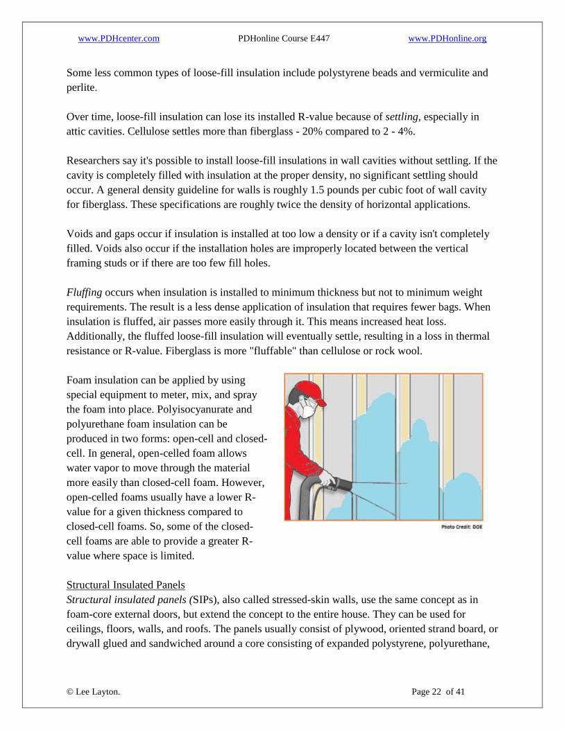
Foam insulation can be applied by using
special equipment to meter, mix, and spray
the foam into place. Polyisocyanurate and
polyurethane foam insulation can be
produced in two forms: open-cell and closed-
cell. In general, open-celled foam allows
water vapor to move through the material
more easily than closed-cell foam. However,
open-celled foams usually have a lower R-
value for a given thickness compared to
closed-cell foams. So, some of the closed-
cell foams are able to provide a greater R-
value where space is limited.
Structural Insulated Panels
Structural insulated panels (SIPs), also called stressed-skin walls, use the same concept as in
foam-core external doors, but extend the concept to the entire house. They can be used for
ceilings, floors, walls, and roofs. The panels usually consist of plywood, oriented strand board, or
drywall glued and sandwiched around a core consisting of expanded polystyrene, polyurethane,

www.PDHcenter.com PDHonline Course E447 www.PDHonline.org
© Lee Layton. Page 23 of 41
polyisocyanurate, compressed wheat straw, or epoxy. Epoxy is too expensive to use as an
insulator on its own, but it has a high R-value (7 to 9), high strength, and good chemical and
moisture resistance.
SIPs are manufactured by sandwiching a core of rigid foam insulation between two oriented
strand board (OSB) structural skins. Built to standards in a factory and then shipped to the
building site, SIPs are assembled like building blocks. What makes this technique so special is
that SIPs can be custom designed for each building. The result is an extremely well built, energy
efficient, and cost effective structure. Moreover, building with SIPs reduces construction and
labor time, and there is very little waste.
SIP outperforms conventional wall building methods in virtually every category. SIP walls have
a superior R-value, or thermal resistance, when compared to conventional framing. This is based
on the whole wall thermal performance, rather than just the rated R-value of the insulation,
taking into account thermal bridges between wall studs. Overall, SIP walls have an R-value of R-
14 compared to R-9.8 for a conventional insulated wall. The R-values of SIP walls will
vary depending on the thickness and type of core material used.
The air-tight construction of SIP buildings significantly reduces energy loss and makes them
very efficient. SIP buildings reduce the energy used to heat and cool by up to 50%. Buildings
constructed with SIPs are extremely quiet and nearly dust and allergen free. SIP buildings
require mechanical ventilation systems to bring controlled amounts of fresh air in, and to vent
stale and moisture-laden air to the outside. This process allows for the filtration of incoming air
and the removal of allergens and humidity for better indoor-air quality.
SIPs not only have high R-values but also high strength-to-weight ratios. An SIP typically
consists of 4- to 8-inch thick foam board insulation sandwiched between two oriented strand
boards (OSB) or other structural facing materials. Manufacturers usually can customize the
exterior and interior sheathing materials according to customer requirements. The facing is glued
to the foam core. The panel is then either pressed or placed in a vacuum to bond the sheathing
and core together.
The majority of SIPs are manufactured with expanded polystyrene (EPS) foam board or
beadboard insulation. This type of SIP has a nominal R-value of about 4 to 5 per inch of
thickness. They are available in almost any size; however, common wall panels are 48”×96” and
weigh 110 pounds.
Some manufacturers choose to use polyisocyanurate or polyurethane as the insulating material.
Foam board or liquid foam can be used to manufacture an SIP. Liquid foam can be injected

www.PDHcenter.com PDHonline Course E447 www.PDHonline.org
© Lee Layton. Page 24 of 41
between two wood skins under considerable pressure. When hardened, the foam produces a
strong bond between the foam and the skins.
Polyurethane and polyisocyanurate SIPs have a nominal R-value of around R-6 to R-7 per inch
of thickness. Liquid foams contain a blowing agent, some of which escapes over time, reducing
the initial R-value of the SIP from about R-9 to R-7.
Wall panels made of polyisocyanurate or polyurethane are typically 3.5 inches thick. Ceiling
panels are up to 7.5 inches thick. These panels, although more expensive, are more fire and water
vapor-diffusion resistant than EPS. They also insulate 30%–40% better per given thickness.
Compressed Straw Core Insulated Panels are more environmentally friendly than the other types
because they're made from renewable, recycled waste agricultural straw. However, straw SIPs
offer less insulation per inch of thickness, and they are considerably heavier.
The following lists a few of the advantages and disadvantages of SIP insulation.
Advantages
Strong. Able to bear loads, including external loads from precipitation and wind.
Faster construction than stick-built house. Less lumber required.
Insulate acoustically.
Impermeable to moisture.
Can truck prefabricated panels to construction site and assemble on site.
Create shell of solid insulation around house, while reducing bypasses common with
stick-frame construction. The result is an inherently energy-efficient house.
Do not use formaldehyde, CFCs, or HCFCs in manufacturing.
True R-values and lower energy costs.
Disadvantages
More expensive than other types of insulation.
Thermal bridging at splines and lumber fastening points unless a thermally broken spline
is used.
Insulating Concrete Forms
Insulating concrete forms (ICFs) are another technology for improving the energy efficiency of
wall structures. ICFs are poured concrete walls with forms. The concrete walls are sandwiched
between two layers of foam insulation, called forms, which remain in place as part of the
building’s wall assembly. These forms are either pre-formed, interlocking blocks or separate
panels connected with plastic ties. Typically, expanded polystyrene foam is used, which
provides insulation and barriers to sound. They also provide the backing needed to hang
drywall on interior and exterior coverings such as siding, stucco, or brick.

www.PDHcenter.com PDHonline Course E447 www.PDHonline.org
© Lee Layton. Page 25 of 41
The insulating R-values for ICF walls typical range from R-17 to R-26. A standard 2”x 4”
timber-studded frame wall, with standard fiberglass insulation, ranges from R-13 to R-15. This
means that buildings with ICF walls require 44% less heating energy and 32% less cooling
energy to maintain comfort in the building. As with SIPs, ICF buildings are built solid, making
them virtually leak free, and diminishing energy loss.
There are several advantages to building with ICFs. The first being that ICFs greatly reduce the
energy required to heat and cool the building because the insulation sandwiching the concrete
walls eliminates gaps and therefore eliminates heating and cooling loss. Also, ICFs
make buildings almost totally sound proof, bug resistant, and fire resistant. Tests have also
concluded that an ICF wall—when compared to a timber-studded wall—is much more resistant
to the structural stress that occurs during earthquakes.
Both the Structural Insulated Panel Association and the Insulation Concrete Form Association
stipulate that using SIPs and ICFs in new construction costs slightly more than conventional steel
and wood framing, typically $0.50 to $5.00 a square foot, depending on the location. Despite the
increased building costs, however, homebuyers benefit through lower utility bills; increased
sustainability, durability, and resale value.
Homes built using an insulating concrete form (ICF) system literally have the insulation built
into the walls as part of the structure. This system creates walls that have a high thermal
resistance, with R-values typically above R-17. Even though ICF homes are constructed using
concrete, they look just like traditional stick-built homes.
There are three basic types of ICF systems that use either foam board or foam blocks. A flat
system yields a continuous thickness of concrete, like a conventionally poured wall. A grid
system creates walls using a waffle pattern—the concrete is thicker at some points than others. A
post-and-beam system consists of discrete horizontal and vertical columns of concrete, which are
completely encapsulated in foam insulation.
Another ICF system uses foam board in the center of the concrete wall. This is often referred to
as tilt-wall construction. The walls are poured in a form on a flat deck. After curing, the walls are
"tilted" upright into position by a crane. Because the foam board is inside the wall, it reduces
potential problems related to the foam's fire resistance, insect infestation, and moisture.
The foam webbing around the concrete-filled cores of blocks can provide easy access for insects
and groundwater. To help prevent these problems, some manufacturers make insecticide-treated
foam blocks and promote methods for waterproofing them.

www.PDHcenter.com PDHonline Course E447 www.PDHonline.org
© Lee Layton. Page 26 of 41
Advanced Wall Framing
Advanced wall framing techniques can be used to reduce the energy losses through the walls
with little or no additional costs. The effective R-value of traditional frame built walls is not as
good as they first seem because the wood studs within the wall reduce the amount of area that is
insulated. To further explain this concept let’s look at the following example.
Figure 7 shows a typical framing scenario for an 8’ wall section that consists of one corner, a
window frame, and a partition wall. The wall has a vapor barrier, drywall, exterior siding and an
exterior sheathing.
Figure 6
The clear wall R-value is,
Vapor Barrier 0.17
Siding 0.8
Sheathing 0.6
Insulation (3.5”) 11.0
Drywall 0.45
13.02
We would assume the wall has an R-value of 13.02 and this is known as the clear wall R-value.
However, this is not the total wall R-value because of the wall framing material. This wall uses
nine framing studs, two top plates, one bottom plate, plus three additional studs for the window
framing and header, for a total of fifteen 2”x4” (1.5x3.5 nominal) studs. An 8’ wall section with
an 8’ wall height has 64 square feet of area.
The R-value where there are studs (and where there is no insulation) is,
Vapor Barrier 0.17
Siding 0.8
Sheathing 0.6
Stud 4.38
Drywall 0.45

www.PDHcenter.com PDHonline Course E447 www.PDHonline.org
© Lee Layton. Page 27 of 41
6.30
So, in the areas where there are wood studs the wall R-value is only 6.3. The studs comprise 15
ft2 of this 64 ft
2 wall. Therefore, the actual R-value for this wall is,
Clear Wall R-Value 13.02 * 49 ft2 = 638
Stud Wall R-Value 6.30 * 15 ft2 = 94.5
732.5
Effective R-Value = 732.5 / 64 ft2 = 11.44.
The effective R-Value is approximately 88% of the predicted R-value.
This situation is even worse with metal-studded walls since the metal studs have no insulating
value.
Some builders are beginning to use new framing techniques to improve the effective R-value of
walls. Corners and T-wall junctions are two areas that are frequently modified. The following
drawings (Figure 8) show the differences between traditional and advanced framing concepts.

www.PDHcenter.com PDHonline Course E447 www.PDHonline.org
© Lee Layton. Page 28 of 41
Figure 7
Metal Framing
Some new homes are built using metal frames instead of wood. Such frames are not susceptible
to insect problems that can damage wood-framed structures. However, when insulating a metal-
framed building, it is important to recognize that much more heat flows through metal studs and
joists than through pieces of wood. Because of this difference, placing insulation just between
the wall studs, or just between attic or floor joists, doesn't work as well for metal-framed houses
as it does for wood-framed houses. Structures with metal frames need continuous insulating
sheathing over the outside of the wall frame, between the metal framing pieces and exterior
siding in addition to insulating the space between the studs. If the attic has metal joists, place
rigid foam insulation between the joists and the ceiling drywall and to cover the attic joists with
insulation to the extent possible.
Massive Walls
The most common house type in this country is the light-construction frame house. Massive
walls are less common, and include buildings made from concrete, concrete block, and log.
These buildings will use less energy than wood-frame construction in many parts of the country
because they can store heat from the daytime sun to provide needed heat at night, or can cool

www.PDHcenter.com PDHonline Course E447 www.PDHonline.org
© Lee Layton. Page 29 of 41
down at night to reduce air-conditioning loads during the day. Research shows that such massive
wall systems perform best if the insulation is located on the outside of the wall.
Air Films
One final item to consider in walls (and roofs too) is the use of air films. When determining the
overall thermal resistance of a building assembly such as a wall or roof, the insulating effect of
the surface air film is added to the thermal resistance of the other materials. See Table 6.
Table 6
Non-reflective surface R-values for air films
Surface position Direction of heat
transfer R-Value
Horizontal (e.g., a flat ceiling) Upward
(e.g.. winter) 0.61
Horizontal (e.g., a flat ceiling) Downward
(e.g., summer) 0.92
Vertical (e.g., a wall) Horizontal 0.68
Outdoor surface, any position,
moving air 6.7 m/s (winter) Any direction 0.17
Outdoor surface, any position,
moving air 3.4 m/s (summer) Any direction 0.25
In practice the surface values in Table 6 are used for floors, ceilings, and walls in a building, but
are not accurate for enclosed air cavities, such as between panes of glass. The effective thermal
resistance of an enclosed air cavity is strongly influenced by radiative heat transfer and distance
between the two surfaces.
Floor Insulation
Options for floor insulation are basically limited to roll and batt type insulations. Here are a few
tips for installing floor insulation.
www.PDHcenter.com PDHonline Course E447 www.PDHonline.org
© Lee Layton. Page 30 of 41
Run drain lines, electrical wiring, and ductwork below the bottom of the insulation so that a
continuous layer of insulation can be installed. If needed for freeze protection, supply plumbing
may be located within the insulation. The best approach is to run supply plumbing together in a
few joist spaces. The insulation can be split and run around the plumbing.
Seal all air leaks between the conditioned area of the home and the crawl space. High-priority
leaks include holes around bathtub drains and other drain lines, plenums for ductwork, and
penetrations for electrical wiring, plumbing, and ductwork.
Insulation batts with an attached vapor barrier are typically used to insulate framed floors. The
batts should be installed flush against the subfloor to eliminate any gaps, which may serve as
passageways for cold airflow between the insulation and subfloor. The batts also should be cut to
the full length of the joist being insulated and slit to fit around wiring and plumbing.
Insulate the band joist area between the air ducts and the floor as space permits. Use insulation
hangers (wire staves) spaced every 12-18 inches to hold the floor insulation in place without
compressing the insulation more than 1 inch.
The orientation of the vapor barrier depends on the home's location or climate. In most of the
country, the vapor barrier should face upward. However, in certain regions of the Gulf States and
other areas with mild winters and hot summers, it should face downward.
For insulating truss floor systems, it's best to install netting or foam board insulation to the
underside of the floor trusses. Then, fill the space created between the netting or insulation and
subfloor with loose-fill insulation.
Insulating any floors above an unheated garage will help reduce the energy costs for the above
conditioned space. When insulating floors over unconditioned garages, use the following
techniques:
Seal the joint between the header or band joist and the subfloor
Seal the joint between the top or sill plate and the header joist
Seal all air leakage sites in the floor
Trim insulation to fit snugly with no gaps
Staple the Kraft paper to the floor joist from above instead of using wire mesh or stay
wires to hold the insulation in place
Install an air barrier to prevent cold air in the garage from "short circuiting" the insulation
underneath the subfloor

www.PDHcenter.com PDHonline Course E447 www.PDHonline.org
© Lee Layton. Page 31 of 41
Attic & Ceiling Insulation
Loose-fill or batt insulation is typically installed in an attic. Although installation costs may vary,
loose-fill insulation is usually less expensive to install than batt insulation. When installed
properly, loose-fill insulation also usually provides better coverage.
In some houses, it is easier to get complete
coverage of the attic floor with blown-in loose-fill
insulation. Loose-fill insulation must be prevented
from shifting into vents or from contacting heat-
producing equipment (such as recessed lighting
fixtures) by using baffles or retainers.
If batts or rolls are used, the first layer should be
fit between the joists. The second layer should be
placed perpendicular to the first because that will
help to cover the tops of the joists themselves and reduce thermal bridging through the frame.
Also, be sure to insulate the trap or access door. Although the area of the door is small, an un-
insulated attic door will reduce energy savings substantially.
Before installing any type of insulation in an attic, follow these steps:
Seal all attic-to-home air leaks.
Duct exhaust fans to the outside. Use a tightly constructed box to cover fan housing on
attic side. Seal around the duct where it exits the box. Seal the perimeter of the box to the
drywall on attic side.
Cover openings—such as dropped ceilings, soffits, and bulkheads—into attic area with
plywood and seal to the attic side of the ceiling.
Seal around chimney and framing with a high-temperature caulk or furnace cement.
At the tops of interior walls, use long-life caulk to seal the smaller gaps and holes. Use
expanding foam or strips of rigid foam board insulation for the larger gaps.
Install blocking (metal flashing) to maintain fire-safety clearance requirements for heat-
producing equipment found in an attic, such as flues, chimneys, exhaust fans, and light
housings/fixtures unless the light fixtures are IC (insulation contact) rated. IC-rated lights
are airtight and can be covered with insulation.
Make sure insulation doesn't block soffit vents to allow for attic ventilation.
Also insulate and air seal an attic access if it's located in a conditioned part of the house and
properly insulate and air seal any knee walls—vertical walls with attic space directly behind
them—in a home as well.

www.PDHcenter.com PDHonline Course E447 www.PDHonline.org
© Lee Layton. Page 32 of 41
A special ceiling application is cathedral ceilings. Cathedral ceilings must provide space
between the roof deck and ceiling for adequate insulation and ventilation. This space can be
achieved through the use of truss joists, scissor truss framing, or sufficiently large rafters. For
example, cathedral ceilings built with 2x12 rafters have space for standard 10-inch batts with R-
values of R-30 and ventilation.
Foil-faced batt insulation is often used in cathedral ceilings because it has a 0.5 perm rating,
providing the permeability rating often required for use in ceilings without attic spaces. A vent
baffle should be installed between the insulation and the roof decking to maintain the ventilation
channel.
If roof framing provides insufficient space for required insulation, higher insulation values can
be obtained by attaching furring strips to allow additional insulation to be installed, to the
underside of the rafters using high-density batts. For instance, high-density R-30 batts are as
thick as R-25 batts and fit into 2x10 framing. Rigid foam insulation offers a resistance to thermal
bridging through wood rafters. However, rigid foam insulation must be covered with a fire-rated
material when used on the interior of a building.
In a cathedral type attic the insulation is placed on the underside of the roof instead of on the
attic floor. For this arrangement, the attic space is incorporated as a part of the conditioned space
within the house. One advantage of this approach is that the attic will retain any energy lost by
ductwork in the attic. Up to 25% of heating and cooling energy can be wasted by leaky ductwork
in a traditional attic.
A disadvantage of an unventilated attic is that the underside of the roof has a greater area than
the attic floor. The greater area along with the downward-facing geometry, cause this option to
be more costly than insulating the attic floor, so that usually the installed insulation R-value is
less. The lower R-value and the greater area mean that more heat is lost through the cathedral
attic roof than would have been lost through the traditional attic floor. Also, a ventilated attic can
reduce summer air-conditioning loads relative to the cathedral attic. The home owner must
balance these two effects, reduced duct energy losses versus increased heating and cooling loads.
Of course another option is to ventilate the attic, but locate the ductwork elsewhere within the
conditioned part of the house, such as between floors in a multi-story building.
HVAC Ducts
Air ducts supply conditioned air from space heating and cooling equipment to living spaces.
They also return an equal volume of air back to the equipment to be conditioned again.
Ducts are typically made out of thin metal materials that easily conduct heat. Therefore, un-
insulated or poorly insulated ducts in unconditioned spaces can lose through conduction 10%–
www.PDHcenter.com PDHonline Course E447 www.PDHonline.org
© Lee Layton. Page 33 of 41
30% of the energy used to heat and cool a home. The heating and cooling equipment then has to
compensate for the heat loss and gain by conditioning additional air. This added conditioning
increases energy use. In addition, when ducts lose heat through conduction, rooms served by
long duct runs can experience cold blow during the winter because they usually have lower
heating-supply temperatures.
Rigid fiber or fibrous board insulation consists of either fiberglass or mineral wool and is
primarily used for insulating air ducts in homes. It is also used when there is a need for insulation
that can withstand high temperatures.
Fiber or fibrous glass duct board insulation is manufactured from resin-bonded, inorganic glass
fibers. These duct boards are available with coated or faced airstream surfaces. The outside
surface of the boards typically incorporates a factory-applied reinforced aluminum air barrier and
water vapor retarder. They come in a range of thicknesses from 1 inch to 2.5 inches. The boards
can provide an R-value of about R-4.0 per inch of thickness.
On exterior duct surfaces the insulation may be installed by impaling it on weld pins and
securing with speed clips or washers. Weld pins with integral-cupped head washers may also be
used. Un-faced boards can then be finished with reinforced insulating cement, canvas, or
weatherproof mastic. Faced boards can be installed in the same way. Joints between boards are
sealed with pressure-sensitive tape or glass fabric and mastic.
Ducts in conditioned spaces experience minimal conductive losses and gains since they are
exposed to indoor air temperatures. However, these ducts may also require some insulation to
prevent condensation on duct walls and to ensure that conditioned air is delivered at the desired
temperature.
Table 7 shows the recommended R-values by climate for duct insulation in unconditioned
spaces.

www.PDHcenter.com PDHonline Course E447 www.PDHonline.org
© Lee Layton. Page 34 of 41
Table 7
Recommended Duct Insulation R-Values
Climate Type of Heating
Systems
R-values for
Unconditioned
Attic
R-values for
Unconditioned
Basement/Crawlspace
Warm climates with
cooling and minimal
heating requirements
Gas/oil, electric
resistance, or heat pump R-4 to R-8 none to R-4
Mixed climates with
moderate heating and
cooling requirements
Gas/oil, electric
resistance, or heat pump R-4 to R-8 R-2 to R-8
Cold climates Gas/oil, electric
resistance, or heat pump R-6 to R-11 R-2 to R-11
www.PDHcenter.com PDHonline Course E447 www.PDHonline.org
© Lee Layton. Page 35 of 41
Chapter 3
Moisture Control and Ventilation
Properly controlling moisture in a home will improve the effectiveness of air sealing and
insulation efforts, and vice versa. Thus, moisture control contributes to a home's overall energy
efficiency.
The best strategy for controlling moisture depends on the climate and how the home is
constructed. Moisture control strategies typically include the following areas of a home:
Attics
Foundation
Basement
Crawl space
Slab-on-grade floors
Walls.
Air leaks into and out of houses through small openings around doors and window frames and
through fireplaces and chimneys. Air also enters the living space from other unheated parts of the
house, such as attics, basements, or crawlspaces. The air travels through:
Any openings or cracks where two walls meet, where the wall meets the ceiling, or near
interior door frames;
Gaps around electrical outlets, switch boxes, and recessed fixtures;
Gaps behind recessed cabinets, and furred or false ceilings such as kitchen or bathroom
soffits;
Gaps around attic access hatches and pull-down stairs;
Behind bath tubs and shower stall units;
Through floor cavities of finished attics adjacent to unconditioned attic spaces;
Utility chase ways for ducts, etc., and
Plumbing and electrical wiring penetrations.
These leaks between the living space and other parts of the house are often much greater than the
obvious leaks around windows and doors. Since many of these leakage paths are driven by the
tendency for warm air to rise and cool air to fall, the attic is often the best place to stop them. It's
important to stop these leaks before installing attic insulation because the insulation may hide
them and make them less accessible. Usually, the attic insulation itself will not stop these leaks
because of the air flowing through or around the insulation.

www.PDHcenter.com PDHonline Course E447 www.PDHonline.org
© Lee Layton. Page 36 of 41
When natural ventilation has been sharply reduced, as in a more energy-efficient house, it may
be necessary to provide fresh air ventilation to avoid build-up of stale air and indoor air
pollutants. Special air-to-air heat exchangers, or heat-recovery ventilators, are available for this
purpose. It is also possible to incorporate a supply of fresh outside air into your heating and
cooling system. This arrangement can be used to create a slightly higher pressure inside the
home, which will prevent uncontrolled outside air infiltration.
Methods to control moisture problems
Listed below are four methods that, if used effectively, will help control moisture problems in a
home and help the insulation work effectively.
1. Control liquid water
Rain coming through a wall, especially a basement or crawlspace wall, may be less apparent than
a roof leak, especially if it is a relatively small leak and the water remains inside the wall cavity.
Stop all rain-water paths into the home by:
Use a Weather-Resistive Barrier,
Caulk around all windows and doors,
Direct all water coming off the roof away from the house by sloping the soil around the
house so that water flows away from the house,
Use wide overhangs to keep the rain away from your walls and windows, and
Use large gutters and gutter guards to help keep rain from dripping onto the ground near
the house.
2. Ventilate
Ventilation is needed when people generate moisture by cooking, showering, doing laundry, and
even breathing. More than 99% of the water used to water plants eventually enters the air. If an
unvented natural gas, propane, or kerosene space heater is used, all the products of combustion,
including water vapor, are exhausted directly into the living space. This water vapor can add up
to 5 to 15 gallons of water per day to the air inside a home. If the clothes dryer is not vented to
the outside, or if the outdoor vent is closed off or clogged, all that moisture will enter the living
space. Just by breathing and perspiring, a typical family adds about 3 gallons of water per day to
their indoor air. Kitchen and bathrooms especially need ventilation. These vents should go
directly outside, and not to the attic, where the moisture can cause problems. Take care to
prevent loose-fill insulation from clogging attic vents by using baffles or rafter vents. These
baffles also serve to keep the outside air from penetrating into the insulation.
3. Stop Air Leaks
It is very important to seal up all air-leakage paths between living spaces and other parts of the
building structure. Measurements have shown that air leaking into walls and attics carries

www.PDHcenter.com PDHonline Course E447 www.PDHonline.org
© Lee Layton. Page 37 of 41
significant amounts of moisture. Remember that if any air is leaking through electrical outlets or
around plumbing connections into wall cavities, moisture is carried along the same path. The
same holds true for air moving through any leaks between the home and the attic, crawlspace, or
garage. Even very small leaks in duct work can carry large amounts of moisture, because the
airflow in your ducts is much greater than other airflows in the home. This is especially a
problem if ducts travel through a crawlspace or attic, so be sure to seal these ducts properly.
Return ducts are even more likely to be leaky, because they often involve joints between drywall
and ductwork that may be poorly sealed, or even not sealed at all.
4. Plan a moisture escape path
Typical attic ventilation arrangements are one example of a planned escape path for moisture that
has traveled from the home's interior into the attic space. Cold air almost always contains less
water than hot air, so diffusion usually carries moisture from a warm place to a cold place.
Moisture escapes from a wall cavity to the dry outdoors during the winter or to the dry indoors
during the summer, by avoiding the use of vinyl wall coverings or low-perm paint. A
dehumidifier can reduce moisture levels in a home, but it will increase energy use. If using a
humidifier for comfort during the winter months, be sure that there are no closed-off rooms
where the humidity level is too high.
Vapor Diffusion Retarders Installation Practices
It is important for Vapor Diffusion Retarders (VDRs)
to minimize condensation or moisture problems in the
following areas of a building: walls, ceilings, and
floors; under concrete slabs; and in crawl spaces. A
continuous VDR with reliable air sealing is very
important if the building is constructed on a concrete
slab. A VDR with a perm value of less than 0.50
should be used if the water table is high.
In moderate heating climates (less than 4,000 Heating
Degree Days), materials like painted gypsum
wallboard and plaster wall coatings impede moisture
diffusion to acceptable levels and no further VDR is
needed. In more extreme climates, a VDR is
advisable for new construction. VDRs perform best when installed closest to the warm side of a
structural assembly. In cold climates this is towards the interior of the building. In hot/wet
climates, this is towards the exterior of the building.
Reasonable rules-of-thumb to follow when placing vapor retarders are:
VDRs in Walls?
There is some controversy about using a
vapor retarder in walls. If the outside air is
colder and drier than the inside of a home,
then moisture from inside the warm house
will try to diffuse through the walls and
ceiling toward the cold, dry outside air. If the
outside air is hot and humid, then moisture
from outside will try to diffuse through the
walls toward the dry, air-conditioned inside
air. In the past it was assumed that vapor
retarders should be used to try and stop
moisture diffusion. Now, some studies
indicate that if moisture moves both ways for
significant parts of the year, vapor retarder
should not be used in the walls.

www.PDHcenter.com PDHonline Course E447 www.PDHonline.org
© Lee Layton. Page 38 of 41
For climates having 2,200 or more heating degree days (HDD) the VDR should be
located on the warm side of the exterior structural assembly. If possible, locate it on the
inside of the assembly using the "one third, two thirds rule": the VDR has one third of the
cavity insulation to its warm side, two thirds to the cold side. This protects the retarder
from physical damage through errant construction or remodeling activities.
For climates with fewer than 2,200 HDD (cooling-dominated climates) where the
building is near, but not quite in, the 2,200 HDD zone place the VDR in the same
location as climates farther north.
Farther south (about 1,900 HDD) the location is irrelevant.
For climates even farther south than this, and one generally hotter and more humid
VDR’s are often not used. This is due to the winter heating loads and summer cooling
loads being roughly equal. Any choice of location ends up having the VDR on the wrong
side of the structure half of the year. Some research suggests that a VDR should be
applied directly under the exterior finish.
When installing a VDR it should be continuous and as close to perfect as possible. This is
especially important in very cold climates and in hot and humid climates. Be sure to completely
seal any tears, openings, or punctures that may occur during construction. Cover all appropriate
surfaces. Otherwise moist air condensing within the cavity may cause damp insulation. The
thermal resistance of wet insulation is dramatically decreased, and prolonged wet conditions will
induce mold and wood rot.
Except for extensive remodeling projects, it's difficult to add materials like sheet plastic as a
VDR to an existing home. However, many existing homes do not really need a more effective
VDR than the more than likely numerous layers of paint on their walls and ceilings. These
multiple layers are quite effective as a VDR in all but the most extreme northern climates.
Vapor barrier paints are also an effective option for colder climates. If the Perm rating of the
paint is not indicated on the label the paint label may still give a hint as to the perm rating. The
label usually indicates the percent of pigment and to be a good VDR it should have a relatively
high percent of solids and thick in application. Glossy paints are more effective VDRs than flat
paints and acrylic paints are generally better than latex paints. When in doubt apply more coats
of paint. However, it's best to use paint labeled as a VDR and follow the directions for applying
it.
In any case, the key to controlling unwanted water vapor movement is the careful air-sealing of
gaps in the structure and not the VDR alone.

www.PDHcenter.com PDHonline Course E447 www.PDHonline.org
© Lee Layton. Page 39 of 41
Ventilation
Adequate ventilation, particularly in attics and crawl spaces, will prevent moisture from
condensing on the insulation or the building structure. Vent openings in attics and crawl spaces
must be placed so that air can flow in one opening, across the insulated area, and out the other.
This is usually made possible through cross-ventilation.
Crawl spaces under the house should be covered. This is to slow ground moisture from
evaporating into the crawlspace and condensing there. Cross-ventilation can be achieved in crawl
spaces by placing vents at direct opposite sides of the space. The venting area should be one
square-foot for each 150 square feet of crawl space/floor area.
Attics are best ventilated by taking advantage of convection, the natural tendency of warm air to
rise. In an attic, this is called the chimney effect. Half of the vents are placed at the eaves (the
lower part of the attic) and half at the gables or ridges above. The heat of the sun and the force of
wind naturally provide attic cross-ventilation with this system.
Cross-ventilated attics must provide one square foot of net free area (NFA) for each 300 square
feet of ceiling area (with or without a vapor barrier). See Table 8.
Table 8
Net Free Area (NFA) of Attic Vents
Type of Attic Ventilation Divide Attic Space by
Cross-Ventilated (with or without vapor barrier) 300
Not Cross-Ventilated without vapor barrier 150
Not Cross-Ventilated with vapor barrier 300
If the attic is not cross-ventilated increased ventilation may be recommended. If no vapor barrier
is installed, one square foot NFA should be provided for each 150 square feet of ceiling area. If
the attic does not provide this much ventilation, it may be easier to install a vapor barrier. Attics
insulated with a vapor barrier must provide one square foot of NFA for each 300 square feet of
ceiling area when not cross-ventilated.
Mesh screens and/or rain louvers can reduce the net free area of vents by as much as one-third.
Unless the term "free air" is stamped on the louver, their size must be increased to account for
the loss of net free area. Table 9 has area reduction factors for various screens.

www.PDHcenter.com PDHonline Course E447 www.PDHonline.org
© Lee Layton. Page 40 of 41
Table 9
Net Free Area Reduction Factors
Type of Covering Reduction Factor
¼” Hardware Cloth 1.00
¼” Hardware Cloth with Rain Louvers 2.00
#8 Mesh Screen 1.25
#8 Mesh Screen with Rain Louvers 2.25
#16 Mesh Screen 2.25
#16 Mesh Screen with Rain Louvers 3.00
No Screen with Rain Louvers 2.00
For example, a 1,500 square-foot cross-ventilated attic with a vapor barrier will require one
square foot of net free area for each 300 square-feet of attic space or 5.0 square feet. If the
ventilation is just covered with ¼” hardware cloth then no reduction in area is required.
However, if the ventilators have both hardware cloth and rain louvers then the effective net free
area is reduced by a factor of 2.0 (See Table 9) so the NFA is then 2.5. Therefore, the number of
ventilators would have to be doubled to yield the same effective NFA.

www.PDHcenter.com PDHonline Course E447 www.PDHonline.org
© Lee Layton. Page 41 of 41
Summary
Building an appropriate thermal envelope in a home will reduce energy costs and improve the
homeowner’s comfort. In this course we have looked at how to insulate the various areas in a
typical home, how to determine the benefits of adding insulation, and reviewed the basic steps to
controlling moisture in a residential structure. These guidelines will help ensure a more
comfortable and energy efficient home.
Copyright © 2014 Lee Layton. All Rights Reserved.
+++