energy efficiency of machinery hydro-pneumatic …energy efficiency of machinery hydro-pneumatic and...
TRANSCRIPT
Energy Efficiency of Machinery Hydro-Pneumatic
and Climate Impact
MARIUS-CONSTANTIN POPESCU1 NIKOS E. MASTORAKIS
2
MIRCEA GRIGORIU3 JEAN-OCTAVIAN POPESCU
4
1Faculty of Electromechanical and Environmental Engineering, University of Craiova
Decebal Blvd, No.107, Craiova 200440, ROMANIA 2Technical University of Sofia, Kliment Ohridski Blvd, Sofia 1000, BULGARIA
3University “Politehnica”, Bucharest, ROMANIA
4College “Elena Cuza”, Craiova, ROMANIA
[email protected] [email protected] [email protected]
Abstract- In practice, due to various over-the loss of pregnancy considered by designers as a security measure, the pump provides a flow chosen much higher than calculated. The main greenhouse gases (GHGs) producer is represented by the fossil burning systems. The paper presents the effect on the
GHGs emission combined with the economic effects of a new pumping system method of automatic mixing of hot and cold water circulated with variable speed driving pumps and adjustable vanes.
Considering the potential economic and environmental effects combined with the social one, The heating systems represent a sensitive sector of the energy consumers’ basket, strengthen by the unpredictable primary energy price fluctuation, the recent financial crisis and the population
expectations. This paper tries optimizing operation of machinery, hydro-pneumatic.
Key-Words: - Modeling and optimization, Greenhouse gases, Heating systems, Economic effects.
1 Introduction In the actual international and European frame, it is important to accelerate the development and
deployment of cost-effective low carbon and energy efficiency technologies. The European
Union considers an absolute priority the GHGs emission mitigation, in regulation and in technical initiatives frame for low carbon technologies
improvement and generalization [1]. One specific European initiative is the
commitment to reduce with 20% GHGs emission by the year 2020. One of the most important solution proposed by the European Commission are
the Energy efficient technologies, which tend to have high upfront costs. From energy changing
point of view, the attention is focused to hydraulic generator and electrical motor characteristics, referring to the energy efficiency and general
behavior. The Eastern European Countries have a special
situation, considering the heating systems exceptional diversity of dimensions, caloric power necessities, fuel, technical solutions, age, ownership
and technical disposal, as a result of the chaotic and rapid rehabilitation and modernization process,
after 1991. If the large energy producing units were
more or less modernized on different types of funds, especially by Joint Implementation projects
after the Kyoto Protocol ratification by many potential donor and host countries, the secondary heating installations are not in the light of investors
and authorities In the conclusion there are analyzed the ecologic and economic energy reduction effects.
In the last years, the heating solutions register a dynamic evolution in two directions: utilization of the renewable energy sources; modernization of the
producing and utilization equipments. It remains an important part of poor people clients of the old
central heating systems, bat some of them try to avoid even a normal exploitation. This situation produces unbalances and disturbs the central
systems operation, reducing drastically their efficiency. A good opportunity for both individual
consumers and central systems is a consistent improvement of their efficiency, by rehabilitating the existing solutions and adopting new technical
efficient solution.
2 The Heating Systems Conventional, mixing or injection-type, systems heating set-ups characteristics are:
WSEAS TRANSACTIONS on FLUID MECHANICSMarius-Constantin Popescu, Nikos E. Mastorakis, Mircea Grigoriu, Jean-Octavian Popescu
ISSN: 1790-5087 206 Issue 3, Volume 5, July 2010

- The circulator pump and the control valve
fitted in operate independently, without coordination between the two components.
- There is no system knowledge about the hydraulic conditions in the heating circuit, so the
hydraulic energy supplied may be destroyed by control elements. - Discharge head of the variable-speed circulator
pump remains constant, irrespective of the actual load conditions, i.e. irrespective of external
temperature. Systems produce a constant volume flow rate through the consumer installations. As a result,
part-load conditions, which account for more than 95% of the operating period, result in the circulator
pump handling predominantly cold return water most of the time. In the systems with water recirculation, the
volume flow in the supply line is coupled with the volume flow of the cold return water pumped
through the mixing line, as seen in Fig. 1.
Fig. 1: Static characteristics of pump and
installation.
mstotal QQQ 21 += (1)
where:
totalQ - radiator total flow,
sQ1 - supply flow from the kettle,
mQ2 - mixing flow transferred from by-pass.
Thermal output of the heating circuit can be adjusted according to the temperature differential.
Then, predominantly cold return water is pumped through the heating circuit under part-load conditions.
3 Methods of Adjustment It is assumed that the initial network characteristic curve calculated and determines the operation of a
recirculation pump is provided in the operating point A, point near optimal efficiency (Fig. 2a).
Real network generates fewer miscarriages and
actual operating point will be point B, with flow QB >QA (Fig. 2b) [11], [13].
Opportunities to return to the desired flow QA are:
a)
b)
Fig. 2: Explanatory flow adjustment.
1. Obstruction by a valve. By closing its progressively increasing load losses, the
characteristic redresându network by focusing near the operating point B to point A (this is achieved by thermostatic valves fitted to radiators). Also, to
achieve additional burden may be placed between 2 clamps on a diaphragm pump repression [3], [8].
The advantage of using this method are: - is very simple and provides a gradual adjustment
(made of bath), without major investment; - to achieve a slight reduction in energy consumption of the pump.
The limitations of the method are given by the fact that this solution adjustment determined, in
comparison with other solutions, a large waste of energy.
WSEAS TRANSACTIONS on FLUID MECHANICSMarius-Constantin Popescu, Nikos E. Mastorakis, Mircea Grigoriu, Jean-Octavian Popescu
ISSN: 1790-5087 207 Issue 3, Volume 5, July 2010

1. Decrease rotor diameter machine. Changing
the rotor diameter is established at a lower pump characteristic feature of the network at the point C,
point of operation with the same rate as the point A (Fig. 3).
Fig. 3: Explanation of flow adjustment first hydro
machine rotor diameter change.
Advantages: - simple and inexpensive solution (rotor being
provided by the manufacturer), applicable pump power between between 5 and 20 kW; - saving more than obturării method.
Disadvantages: - immobilization pump for removal and changing of
the rotor; - beach limited adjustment (wheels can not be reduced only to a certain limit) - in case of
excessive contraction, the rotor will be replaced with a new one - small loss of hydraulic efficiency.
3. Change speed [4], [6]. This method, like the previous one, is based on reducing the speed of the pump characteristic curve in a way that it passes
through point C. Thus, a rotational speed of 2117 rpm results in a characteristic of the pump virtually
identical to that obtained using a rotor diameter of 110 (Fig. 4). And so the same operating point C.
Fig. 4: Explanation of flow adjustment by changing
the rotational speed of the pump.
Changing speed can be simple and a good
functioning but requires expensive investment in relation to characteristics of the equipment.
Pump: - some have more easily switch speeds (2 or 3
speed pumps with selector can be mounted in different positions); - other (modern) are provided from the factory
with variable speed - but others (in generally the oldest manufacturing) have only one speed. In this
case, involving the purchase of a speed variation frequency converter, quite expensive. This is the most easily adaptable to the conditions of various
flow regimes [1]. Benefits:
- to achieve a significant reduction in energy consumption from the point of view, the same order as the rotor diameter is reduced;
- adapting the exact desired flow depending on the situation (or pulley for variable speed fans).
Disadvantages: - the solution is costly if necessary purchase of a variable speed;
- for switchable speeds, imperfect adaptability to supradebit.
1. Obstruction and speed variation. While other solutions are possible intermediate stop on the
proposals manufacturers, ie pump speed integrated regulators. In this pump its rotational angular velocity decreases to the point of the network
determined which allows maintaining a constant pressure. This is a solution used for circuits or
radiators with thermostatic valves for circuits with two-way valves (Fig. 5).
Fig. 5: Explanation for adjusting flow through
clogged and flow changes.
In Fig. 6 to represent adequately the situation, moving the operating point of B in D is needed in
differential pressure probe. In its absence, the increased pressure would be reduced when the flow
rate regime would remain constant. If shown in Fig. 6a, the pressure remains constant but if hunt is closed, the flow of the network decreases, resulting
in a decrease in pressure on the joint sections.
WSEAS TRANSACTIONS on FLUID MECHANICSMarius-Constantin Popescu, Nikos E. Mastorakis, Mircea Grigoriu, Jean-Octavian Popescu
ISSN: 1790-5087 208 Issue 3, Volume 5, July 2010

Therefore, some producers, believes that the
decrease in flow rate with change can be achieved by reducing pressure linear (Fig. 6b).
a)
b)
Fig. 6: Explanation of the pump rotational speed
changes depending on pressure.
This solution (shown in the figure by shifting the operating point B to E), in terms of energy use is
more economical than the previous one, agrees in most cases the circuits provided by thermostatic valves [2], [10], [ 12].
3.1 Influence of the Method of Adjustment
Used on Energy Eonsumption If you believe that yields are constant, hydraulic
power absorbed is proportional to the product of pressure and flow Q and H is the rectangle area defined by the axes H, Q and operating points (eg
A, B, C, ...). It is noted that (Fig. 7):
- reducing the flow through seal (on point of operation of B in A) provides a slight decrease of the surface of the rectangle (not too big a leap), and
hence power;
- to maintain constant pressure (operating point
moving from B to D) is without a decrease in energy consumption;
- altering the characteristics of the pump or fan, by reducing the rotor diameter or decrease speed to
maintaining the characteristic curve of the circuit, this providing a significant loss of hydraulic power (rectangle O, HC, C. QA, compared with O, HB, B,
QB, or O, HA, A, QA). A decrease in flow by 20% for a flow equal to 80% of flow rate, results in a
decrease of 50% power (= (80%) 3 under the laws of hydro-pneumatic machines).
Fig. 7: Evaluation of power characteristic curves of
centrifugal hydro-pneumatic machines.
Fig. 8: Electric power absorbed when used methods
of regulating hydro-pneumatic machines.
WSEAS TRANSACTIONS on FLUID MECHANICSMarius-Constantin Popescu, Nikos E. Mastorakis, Mircea Grigoriu, Jean-Octavian Popescu
ISSN: 1790-5087 209 Issue 3, Volume 5, July 2010

Figure 8 summarizes the reduction of consumption
using different methods of adjusting the flow for a pump. Adjust flow by adjusting the angular
velocity of rotation is considered the most elegant method, both in terms of energy consumption and
vibration at low speeds [1], [5]. It is also the most expensive method, but we thank you and a decrease in speed by means of
fixed (by changing drive pulleys). In Fig. 9 is shown the variation of noise in
decibels when adjustment methods described above.
Fig. 9: The noise level for different methods of
hydro-pneumatic adjustment centrifugal machine.
4 Innovative Pump Management
System The system is a control one (high controller), installed downstream of the heating system’s
control unit, as seeing in Fig. 10 [1]. It coordinates the operation of circulator pump and control valve. Depending on the control signal,
the two control valves adjust the resulting volume flow rate pumped through the consumer
installations. At the same time, the appropriate discharge head set point is transmitted to the variable-speed drive of the circulation pump.
It transforms the conventional, constant-flow mixing or injection-type system into a variable-
flow system, as it is presented in Fig. 11, and adjusts the discharge head of the circulator pump to
the reduced volume flow rates via the system control curve.
Fig. 10: The heating system.
Fig. 11: Static characteristics of the pump.
Thermal output of the heating circuit, thP , is
calculated for the design point as the product of volume flow rate Q and temperature. Then:
TQPth ∆⋅⋅= 163.1 (2)
The innovative control concept consists in regulating thermal output by variation of the
temperature differential and the volume flow rate, considerably reducing the water volume to be pumped through the heating circuit.
The radiator diagram illustrates the physical fact that, at identical heat output, the volume flow rates
provided to the consumer installations can be reduced if the supply temperature is increased at the same time, using the higher-level controller. This
results in hydraulic savings regarding both volume
flow rate Q∆ and discharge head H∆ , then
electrical power savings are:
Controller
& vane
High
Controller
Consummer
Pump
Adjust.
Control
Unit
Command
Pipes
WSEAS TRANSACTIONS on FLUID MECHANICSMarius-Constantin Popescu, Nikos E. Mastorakis, Mircea Grigoriu, Jean-Octavian Popescu
ISSN: 1790-5087 210 Issue 3, Volume 5, July 2010

( ) ( )∫ ⋅⋅⋅= dttHtQKPel (3)
where:
elP - electrical necessary power,
K - constant describing the efficiency of the pump,
( )tQ - flow-time characteristic,
( )tH - head-time characteristic.
Another positive effect is that static hydraulic balancing at the main feed manifold is now
automatically performed via the circulator pump, which reduces commissioning costs for the heating
circuit. The new device of the system is the Higher-level
control unit operation. The pressure drop across the valve may amount to several tenths of bar. Supply temperature control is the task of a higher-level
controller. Input signals for this controller are, among others, the external temperature measured
and the supply temperature measured in the heating circuit. Helping with the heating curve stored in the higher-level control unit, the set point for the
supply temperature of the heating circuit is generated on the basis of the external temperature
measured. Based on this set point and the supply temperature measured, the higher-level controller generates the control error signal, which is the input
of a control algorithm. This control algorithm generates a signal, which,
in conventional systems, is then transmitted to the control valve. This output control signal from the higher-level controller is the input for control
system, i.e. it is transmitted to the valves and pump control unit. The control unites translate the signal
into two separate control signals for the two control valves and into a discharge head set point.
5 Mathematical Model of Hydro-
pneumatic Machinery in Relative
Coordinates Dimensionless coefficients for pressure, flow and power output and relative coordinate drive motor
speed of the car, defined by reports [7]
Nt
t
00
,P
P,
d
d,
p
p
0ωω
=ν∆
(4)
where: ∆ p is total pressure developed hydraulic machine, defined as the difference between total
pressure (static and dynamic) to output and total pressure at the entrance, p
0 is the maximum
pressure developed by the machine at zero flow, d
is the flow developed by car, d0 is maximum flow
at zero pressure developed car, Pt is the effective
power flow corresponding to pressure p and d; Pt0 is
effective power that would be obtained for a
pressure p0 and a flow d
0; ω is the absolute value
and Nω the nominal motor speed drive.
Mathematical model used to determine optimum
operating point of the pump is obtained from the application of the laws of two hydro-pneumatic
machinery namely: - Act I, which shows that the flow developed by
car d , is proportional to angular velocity ω drive
it, assuming a constant values of fluid density
( ω≈d );
- Act II, which shows that the total pressure ∆ p
developed car, is proportional to the square drive
angular velocity ( 2p ω≈∆ ).
Hydro pneumatic machine characteristic
equation
0
2
0
pd
dp
−ν=∆ . (5)
Power output, developed the machine, fluid
involvement will be needed once the product of flow and pressure
0
2
0
pd
ddpd
−ν=∆ . (6)
6 Determination of Optimal
Operation of Hydro-Pneumatic
Machines Phenomena in the hydro-pneumatic pumps or centrifugal fans used to work in a well-defined
operating point on the curve characteristic of the machine.
The criterion of optimization. To assess the functioning machine is a criterion adopted energy, represented by achieving a maximum power output
transmitted to the fluid in unit time (useful energy), expressed by function:
J(d)=d∆ p. (7)
Formulation of optimization problem.
Optimization problem is to determine optimum
operating point of the car (d*, p*) to ensure maximum energy required for fluid transport,
evaluated by title:
WSEAS TRANSACTIONS on FLUID MECHANICSMarius-Constantin Popescu, Nikos E. Mastorakis, Mircea Grigoriu, Jean-Octavian Popescu
ISSN: 1790-5087 211 Issue 3, Volume 5, July 2010

J(d)= 0
2
0
pd
dd
−ν =max. (8)
Necessary condition for optimum. Is obtained from the equation resulting from the cancellation of
partial derivatives with respect to useful energy flow:
( )02
0
2
pd
d3
d
pd
−ν=
δ∆∂
=0 . (9)
Optimal amount of flow and pressure. Solving
the previous equation, for ν =1 (nominal regime of
operation), to obtain optimum flow value d*=3
d0 ,
which replaced in equation (4) will give optimum
value of pressure p*= 0p3
2, which means a
maximum power useful, equal to
d*∆ p*= 00dp33
2. Optimal operating point thus
determined (A - Fig. 12), can provide an indication as training hydropneumatic cars electric motor requires the existence of friction.
Fig. 12: Dimensionless characteristics of hydro-
pneumatic machines.
If asynchronous motor involvement there will be a very big difference between theoretical values of
flow and pressure resulting from optimization and resulting in reality from effective involvement of the machine. Locus of maximum power points,
under the law 3 hydro-pneumatic machine, the cubic parabola denoted by 2. For flows d
0 and d
developed car, the pressure losses from the plant
will be given by producible R0d
0
2
and Rd2
. Turning
to the relative coordinates to obtain dimensionless
loss of pressure curve (denoted by 1)
2
0
2
00 d
dr
d
d
R
R
=
, (10)
Analysis of natural extremes. Since the
maximum pressure p0 and the maximum flow d
0
have positive values and the second derivative of
energy (power) useful, calculated optimal flow value is negative:
( )0
0
3
dd
2
2
d
p
3
6
d
pd
0
−=∂
∆∂
=
<0, (11)
means that the result achieved absolute maximum criterion function J. Considering that the optimum
operating point of A
∆
0
*
0
*
d
d,
p
p pump,
corresponding to a certain amount of heat generated by the boiler on site, where the quantity of heat
from the chamber decreases, the car will move a quantity less fluid, the corresponding new thermal
load, reducing the angular speed ν = 1 to ν = 0.8,
corresponding to the new optimal operating point
B
∆
0
*1
0
*1
d
d,
p
p. This leads to a decrease in pressure
and power to the
0
t
P
P useful
0
1t
P
P. Proportional
to the effective power, reduced power required involvement of the car, thereby decreasing energy consumption [9].
7 Energy Savings Practical Demo by
Measurements
7.1 System Characteristics For energy saving demonstration, there is
considered twin-heating installations, using two different automatic control systems, with the main
characteristics presented in table no.1: a conventional 3-ways system and a new pump management system, both with a thermal input of 2
MW, equipped with two stage burner. The main feed manifold is connected directly to the boilers
and feeds four heating circuits. Both distribution systems have readjustment thermo-static valves, considering the rooms’ temperature disturbances,
and differential pressure ( )ctp =∆ .
WSEAS TRANSACTIONS on FLUID MECHANICSMarius-Constantin Popescu, Nikos E. Mastorakis, Mircea Grigoriu, Jean-Octavian Popescu
ISSN: 1790-5087 212 Issue 3, Volume 5, July 2010
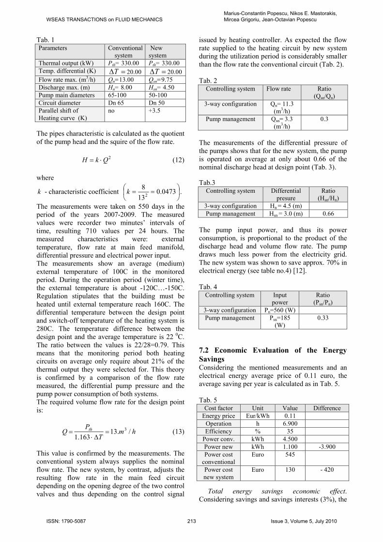
Tab. 1 Parameters Conventional
system
New
system
Thermal output (kW) Pth= 330.00 Pth= 330.00
Temp. differential (K) =∆T 20.00 =∆T 20.00
Flow rate max. (m3/h) Qn=13.00 Qsn=9.75
Discharge max. (m) Hn= 8.00 Hsn= 4.50
Pump main diameters 65-100 50-100
Circuit diameter Dn 65 Dn 50
Parallel shift of
Heating curve (K)
no +3.5
The pipes characteristic is calculated as the quotient
of the pump head and the squire of the flow rate.
2QkH ⋅= (12)
where
k - characteristic coefficient
== 0473.013
82
k .
The measurements were taken on 550 days in the period of the years 2007-2009. The measured values were recorder two minutes’ intervals of
time, resulting 710 values per 24 hours. The measured characteristics were: external
temperature, flow rate at main feed manifold, differential pressure and electrical power input. The measurements show an average (medium)
external temperature of 100C in the monitored period. During the operation period (winter time),
the external temperature is about -120C…-150C. Regulation stipulates that the building must be
heated until external temperature reach 160C. The differential temperature between the design point and switch-off temperature of the heating system is
280C. The temperature difference between the design point and the average temperature is 22 0C.
The ratio between the values is 22/28=0.79. This means that the monitoring period both heating circuits on average only require about 21% of the
thermal output they were selected for. This theory is confirmed by a comparison of the flow rate
measured, the differential pump pressure and the pump power consumption of both systems. The required volume flow rate for the design point
is:
hmT
PQ th /.13
163.1
3=∆⋅
= (13)
This value is confirmed by the measurements. The conventional system always supplies the nominal
flow rate. The new system, by contrast, adjusts the resulting flow rate in the main feed circuit depending on the opening degree of the two control
valves and thus depending on the control signal
issued by heating controller. As expected the flow
rate supplied to the heating circuit by new system during the utilization period is considerably smaller
than the flow rate the conventional circuit (Tab. 2).
Tab. 2 Controlling system Flow rate Ratio
(Qsn/Qn)
3-way configuration Qn= 11.3
(m3/h)
Pump management Qsn= 3.3
(m3/h)
0.3
The measurements of the differential pressure of the pumps shows that for the new system, the pump
is operated on average at only about 0.66 of the nominal discharge head at design point (Tab. 3).
Tab.3 Controlling system Differential
presure
Ratio
(Hsn/Hn)
3-way configuration Hn = 4.5 (m)
Pump management Hsn = 3.0 (m) 0.66
The pump input power, and thus its power
consumption, is proportional to the product of the discharge head and volume flow rate. The pump draws much less power from the electricity grid.
The new system was shown to save approx. 70% in electrical energy (see table no.4) [12].
Tab. 4
Controlling system Input power
Ratio (Psn/Pn)
3-way configuration Pn=560 (W)
Pump management Psn=185
(W)
0.33
7.2 Economic Evaluation of the Energy
Savings Considering the mentioned measurements and an electrical energy average price of 0.11 euro, the
average saving per year is calculated as in Tab. 5.
Tab. 5 Cost factor Unit Value Difference
Energy price Eur/kWh 0.11
Operation h 6.900
Efficiency % 35
Power conv. kWh 4.500
Power new kWh 1.100 -3.900
Power cost
conventional
Euro 545
Power cost
new system
Euro 130 - 420
Total energy savings economic effect. Considering savings and savings interests (3%), the
WSEAS TRANSACTIONS on FLUID MECHANICSMarius-Constantin Popescu, Nikos E. Mastorakis, Mircea Grigoriu, Jean-Octavian Popescu
ISSN: 1790-5087 213 Issue 3, Volume 5, July 2010

effects of system modernization for a period of 20
years is presented in Tab. 6. In the first year, the reduced investment costs for the circuit is -1,059
Euro, the extra price for the new equipments is 402 Euro and the reduced commissioning costs for
heating circuit is - 45 Euro. Tab. 6
Per
iod
(y
)
Red
uce
d
op
erat
ing
cost
s (E
uro
)
Sav
ing
s
(Eu
ro)
Inte
rest
s o
n
sav
ing
s
(Eu
ro)
Sav
ing
s &
inte
rest
s
(Eu
ro)
1 - 415 -1.118 - 33 - 1.501
2 - 450 -1.606 - 49 - 1.655
3 - 450 -2,110 - 61 - 2.173
4 - 490 -2.666 - 80 - 2.744
5 - 490 -3.235 - 95 - 3.329
6 - 530 -3.867 - 115 - 3.978
7 - 530 -4.525 - 130 - 4.649
8 - 570 -5.215 - 155 - 5.367
9 - 570 -5.940 - 177 - 6.126
10 - 609 -6.731 -201 - 6.942
11 - 609 -7.543 - 225 - 7.759
12 - 650 -8.401 - 251 - 8.671
13 - 650 -9.303 - 278 - 9.590
14 - 680 -10.267 - 307 - 10.581
15 - 680 -11.262 - 335 - 11.599
16 - 720 -12.316 - 370 - 12.689
17 - 720 -13.405 - 401 - 13.810
18 - 760 -14.563 - 436 - 15.002
19 - 760 -15.771 - 475 - 16.245
20 - 760 -16.991 - 515 - 17.501
GHGs emission mitigation effect. The total CO2
mitigation corresponding to the energy reduction E∆ is [2]
yearkgCOEC /8.012
4436.0 2×∆××=∆ (14)
Then, for the estimated energy saving of 3,800kWh/year the GHGs mitigation is about
4,012.8 kg C02/year.
8 Conclusions The economy generated by the proper adjustment of pump is always profitable if: item is oversized power is high, annual operating time is great
variation in loads during operation in different seasons or different times of day or night is great,
the cost of electricity is high and investment is minimal.
When the pump factory has more speed, the economics justify changing speed pump (electrical coupling modification or use of a selector), so the
cost is virtually nil.
Also, in case of emergency replacement (for
technical reasons), increased cost of an integrated variable speed pumps is rapidly amortized (pay-
back time 2-3 years). Instead, use an external variable speed power is not justified for amri and /
or a highly variable load profile.
References [1] Boteanu N., Popescu M.C., Manolea Gh., Popescu-Perescu L., Vlase Gh., Brindusa C.,
Optimal Control of Electric Drives Acceleration
with Static Torque with Constant and Speed
Proportional Component and Heating Outline
Proceedings of the 11th WSEAS International Conference on Automatic Control, Modelling and
Simulation, pp.178-183, Istanbul, Turkey, 30 May -1 June 2009.
[2] Bulucea C.A., Nicola D.A., Brandusa C., Cismaru D.C., Manolea Gh., Popescu M.C., Embodied Energy and Environmental Impact in
Electric Transportation Systems, Proceedings of the 4th IASME/WSEAS International Conference on
Energy & Environment (EE'09), pp.232-239, Cambridge - UK, 22-23 February 2009.
[3] Grigoriu M., Popescu M.C., Hydropower
Preventive Monitoring Action Plan, Proceedings of the 5th IASME/ WSEAS International Conference
on Energy&Environment (EE'10), Recent Advances in Energy & Environment, Published by
WSEAS Press, pp.265-270, Cambridge, February 22-25, 2010. [4] Grigoriu M., Popescu M.C., Popescu L.G.,
Popescu C., Dinu D.C., Environmental Air
Conditioned Requirements New Approach,
Proceedings of the 5th IASME/WSEAS International Conference on Energy & Environment (EE'10), Recent Advances in Energy &
Environment, Published by WSEAS Press, pp.257-260, Cambridge, February 22-25, 2010.
[5] Grigoriu M., Popescu M.C., Popescu L.G., Dinu D.C., Popescu C., A Wind Farm Balancing
Analysis, Proceedings of the 5th IASME/WSEAS
International Conference on Energy & Environment (EE'10), Recent Advances in Energy &
Environment, Published by WSEAS Press, pp.261-264, Cambridge, February 22-25, 2010. [6] Mastorakis N., Popescu M.C., Bulucea C.A.,
Analysis in Time-Frequency Domain of
Asynchronous Motors Control with Inverter
Switching at Zero Voltage, Proceedings of the 8th WSEAS International Conference on Education and
Educational Technology EDU’09: Advanced Educational Topics and Technologies, pp.126-132, Published by WSEAS Press Genova, October 17-
20, 2009.
WSEAS TRANSACTIONS on FLUID MECHANICSMarius-Constantin Popescu, Nikos E. Mastorakis, Mircea Grigoriu, Jean-Octavian Popescu
ISSN: 1790-5087 214 Issue 3, Volume 5, July 2010
[7] Popescu M.C., Popescu-Perescu L., Manolea
Gh., Mastorakis N., New Management for the
Control Three Tank System, WSEAS Transactions
on Systems and Control, Issue 11, Vol.4, pp.561-570, November 2009.
[8] Popescu M.C., Bulucea C.A, Manolea Gh., Vladu C., Variables Optimization of Building Air
Conditioning System, Proceedings of the 8th
WSEAS International Conference on System Science and Simulation in Engineering
ICOSSSE’09: Systems Theory and Advanced Simulation Techniques, pp.226-232, Published by WSEAS Press, Genova, October 17-20, 2009.
[9] Popescu M.C., Manolea Gh., Perescu-Popescu L., Drighiciu A., Implementation of New Solution
Software for Three Tank System Control, Proceedings of the 11th International Conference on Mathematical Methods and Computational
Techniques in Electrical Engineering (MMACTEE'09), Published by WSEAS Press,
pp.202-208, Vouliagmeni Beach, Greece, September 28-30, 2009.
[10] Popescu M.C., Olaru O., Comanda optimală a
vitezei pompelor hidraulice din centralele termice, Analele UniversităŃii „Constantin Brâncuşi”, pp.15-
22, A-XI-a EdiŃie a ConferinŃei ŞtiinŃifice a FacultăŃilor de Inginerie, cu participare
internaŃională, Târgu-Jiu, 3-4 Noiembrie, 2006. [11] Popescu M.C., Popescu L.G., Grofu F., Optimal Control of Driving Systems, International
Review of Automatic Control, November 2009. [12] Popescu M.C., Mastorakis N., Borcosi I.,
Popescu L., Asynchronous Motors Drive Systems
Command with Digital Signal Processor, International Journal of Systems Applications,
Engineering & Development, Issue 2, Vol.3, pp.64-73, 2009.
[13] Popescu M.C., Grigoriu M., Optimizing
Operation of Hydro-pneumatic Machineries,
Proceedings of the 10th WSEAS, International
Conference on Energy and Environment Technologies and Equipment (EEETE '10),
Bucharest, Romania, April 20-22, 2010.
WSEAS TRANSACTIONS on FLUID MECHANICSMarius-Constantin Popescu, Nikos E. Mastorakis, Mircea Grigoriu, Jean-Octavian Popescu
ISSN: 1790-5087 215 Issue 3, Volume 5, July 2010