energy efficient and reliable embedded computing systems · 0 fault tolerant and low-power embedded...
TRANSCRIPT

University
of Southampton
ICSA, School of Informatics, University of Edinburgh, Nov.15-2007
Energy efficient and reliable embedded computing systems
Energy efficient and reliable Energy efficient and reliable
embedded computing systemsembedded computing systems
Bashir M. Al-Hashimi
Bashir M. Al-Hashimi

OutlineOutline
� Overview of research activities focusing on
0 Automated low-power system-level design flows
0 Fault tolerant and low-power embedded systems
� Outline of other current projects
� Concluding remarks and future problems
� Overview of research activities focusing on
0 Automated low-power system-level design flows
0 Fault tolerant and low-power embedded systems
� Outline of other current projects
� Concluding remarks and future problems
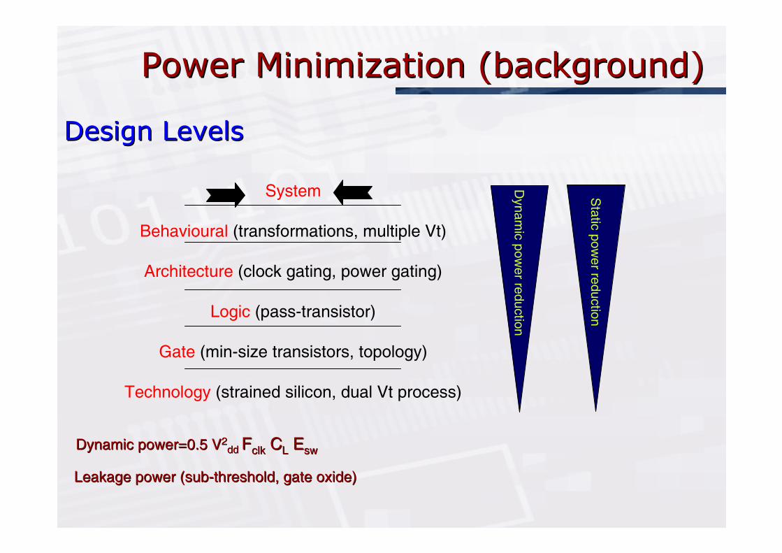
Power Minimization (background) Power Minimization (background)
System
Behavioural (transformations, multiple Vt)
Architecture (clock gating, power gating)
Logic (pass-transistor)
Gate (min-size transistors, topology)
Technology (strained silicon, dual Vt process)
Design LevelsDesign Levels
Dynamic power=0.5 VDynamic power=0.5 V22dd dd FFclkclk CCLL EEswsw
Leakage power (subLeakage power (sub--threshold, gate oxide) threshold, gate oxide)
Dynam
ic p
ow
er re
ductio
n
Sta
tic p
ow
er re
ductio
n

Software Power Optimisation (background)Software Power Optimisation (background)
� Individual instructions: fundamental unit of SW, similar to gates in HW
� Program transformation techniques aims to reduce
0 use of instructions (MOV, JUMP,..) that consume large amount of supply current
0 memory access and unnecessary instruction fetching instruction involves memory consume energy > instructions involve registers
� Operating system techniques
0 Identify program regions where processor can be slowed down to reduce dynamic power through V/F scaling
0 Shut down unused parts of system to reduce leakage power

Embedded Computing Systems, Embedded Computing Systems, SoCSoC, , MulticoreMulticore,..,..
... ... ... ...
int main(int argc, char **argv) {Build_Interface();EventTrigger();while (!end_bs(&bs)) {
... ... ... ... ... ... ...
decode_info(&bs, &fr_ps);}
}
sync = seek_sync(&bs, SYNC_WORD);
... ... ... ...
void EventTrigger() {InitTriggerControl();while (Event) ReadEvent();switch (Event) {
case 0: ... ... ...case 1: ... ... ...
}
}
... ... ... ... ...
…
…
System design requires optimisation in both hardware
(computation units, memory, communication) and
software (application and system)
CPU
ASIC
DSP
FPGA
MEM
MEM
CA
N-B
usIn
terf
ace
Inte
rfa
ce
Inte
rfa
ce
Inte
rfa
ce
DVS-Cont
DVS-Cont
C1
C3C2
C4
C5
I/O DAC ADC
Speaker Mic
Display &Keyboard

SystemSystem--Level Design Flow* Level Design Flow*
*M. Schmitz, B. Al*M. Schmitz, B. Al--HashimiHashimi, P. , P. ElesEles, , ““System level design techniques for energy embedded systemsSystem level design techniques for energy embedded systems””, , KluwerKluwer Publishers, 2004Publishers, 2004
0101010010101010001001
001001010000100100010101010001001
HW SW
Specification
Co-Synthesis
HW Synthesis SW Synthesis

Design Flow: SpecificationDesign Flow: Specification
Abstract Graph
Representation:
e.g.:-Finite State Machine
-Petri Net
-Task Graph
High-Level Languages:
e.g.: - SystemC
- VHDL / Verilog
- C / C++ / JAVA
for (i=0;i<x;i++) {
a[i] += b[i];
}
Capturing system functionality using conceptual modelsCapturing system functionality using conceptual models

Design Flow: CoDesign Flow: Co--synthesis synthesis
0101010010101010001001
001001010000100100010101010001001
HW SW
Specification
Co-Synthesis
HW Synthesis SW Synthesis
SYSTEM-LEVEL
CO-SYNTHESIS
Evaluation
Architecture Allocation
Task Mapping
Scheduling
Energy Management
User
driven
Oute
r lo
op
inner
loop
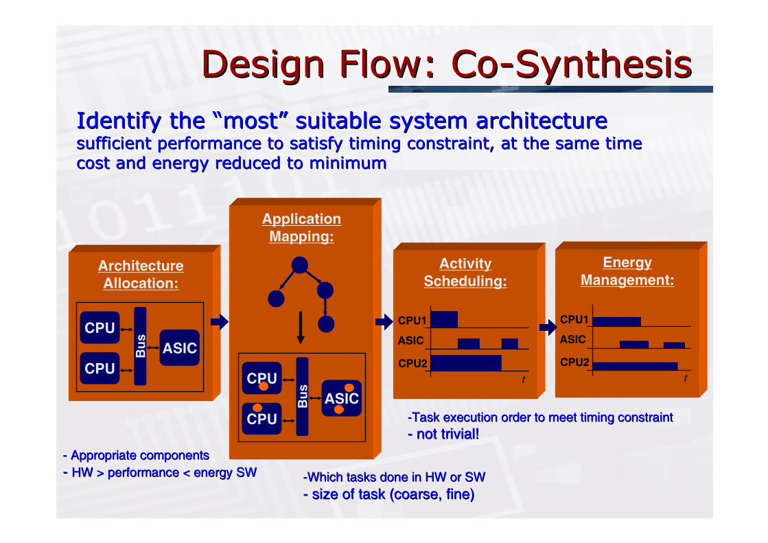
Design Flow: CoDesign Flow: Co--SynthesisSynthesis
Architecture
Allocation:
CPU
CPU
ASICBu
s
Application
Mapping:
CPU
CPU
ASICBu
s
Activity
Scheduling:
t
CPU1
ASIC
CPU2
Energy
Management:
t
CPU1
ASIC
CPU2
Identify the Identify the ““mostmost”” suitable system architecturesuitable system architecturesufficient performance to satisfy timing constraint, at the samesufficient performance to satisfy timing constraint, at the same timetime
cost and energy reduced to minimumcost and energy reduced to minimum
--Task execution order to meet timing constraint Task execution order to meet timing constraint
-- not trivial! not trivial!
--Which tasks done in HW or SWWhich tasks done in HW or SW
-- size of task (coarse, fine)size of task (coarse, fine)
-- Appropriate componentsAppropriate components
-- HW > performance < energy SW HW > performance < energy SW

Tasks ProfilingTasks Profiling
� Partitioning and Scheduling require tasks execution time and energy cost
0 In HW (HDL model of task)
• Execution time through simulation
• Energy estimation through power analysis on synthesised designs
0 In SW (coding of task)
• Execution time through instruction-set simulator
• Energy estimation= average power (pre characterised)*no. clock cycles*frequency
Commercial and academics timing and power estimation tools existCommercial and academics timing and power estimation tools exist

Design Flow: HW/SW SynthesisDesign Flow: HW/SW Synthesis
0101010010101010001001
001001010000100100010101010001001
HW SW
Specification
Co-Synthesis
HW Synthesis SW Synthesis Transformation of system
architecture into physical
implementation

Design Flow: HW/SW SynthesisDesign Flow: HW/SW Synthesis
Co-Synthesis
HW Synthesis:
(ASICs & FPGAs)
High-level Synthesis
RTL model
Logic Synthesis
Gate-level model
Layout Synthesis
Behavioural Spec.
SW Synthesis:
(GPPs & ASIPs)
Compiler
Assembler code
Assembler
Machine code
High-level Language
Co-Simulation
Co-Verification

Energy ManagementEnergy Management
� Dynamic Power Management
0 Idle components shutdown
� Dynamic Voltage and Frequency Scaling
- Non-uniform workload, MPEG order of magnitude >MP3
- Introduce slack times (deadline-finish time) and used to reduce processor performance to save energy
- Adapt processor performance through V/F scaling
� Dynamic Power Management
0 Idle components shutdown
� Dynamic Voltage and Frequency Scaling
- Non-uniform workload, MPEG order of magnitude >MP3
- Introduce slack times (deadline-finish time) and used to reduce processor performance to save energy
- Adapt processor performance through V/F scaling
Task1
Task2
Task3
0.7V,60mW,150MHz
1.3V,450mW,600MHz
1.6V,900mW,800MHz

Energy Management: DVSEnergy Management: DVS--ProcessorProcessor
f. Reg.
µP Core
I/O SRAM
DC/DCConverter
VCO
+Battery
BUS
df
ddV
cf
Examples:
• ARM (IEM)
• AMD (PowerNow)
• INTEL (Xscale)
• TRANSMETA
Intel Xscale
1.1V/150MHz
1.6V/600MHz
2.0V/800MHz

Design Flow: CoDesign Flow: Co--synthesis synthesis
0101010010101010001001
001001010000100100010101010001001
HW SW
Specification
Co-Synthesis
HW Synthesis SW Synthesis
SYSTEM-LEVEL
CO-SYNTHESIS
Evaluation
Architecture Allocation
Task Mapping
Scheduling (offline/online)
Energy Management
User
driven
Oute
r lo
op
inner
loop
--Mapping and Scheduling NPMapping and Scheduling NP--hard problemshard problems
-- Heuristic methods employedHeuristic methods employed

DVS Example (Scheduling)DVS Example (Scheduling)
MEM MEM
MEM
τ0τ4 τ5
τ3 τ6
τ2
τ1
Interface
Bus
InterfaceDVS-PE0 PE1
Interface DVS-PE2
Target architecture and mapping
τ τ4
τ0
τp=
2.0
ms
τ6θ6
3 τ54,5θ
τ21
=1.4ms
=1.6ms
Task graph
PE2200.3τ6
PE0900.2τ5
PE0700.4τ4
PE2400.1τ3
PE1150.4τ2
PE1200.3τ1
PE1100.3τ0
Mapped toPower (mW)Exe. Time (ms)Task
Task properties (communication cost=0)

DVS Example (cont..) DVS Example (cont..)
PE0
PE1
PE2
4τ τ
5
0ττ1 τ
2
3τ
6τ
(mW)P
t(ms)
E=71 Jµ
1 1.61.4
0.3 0.6 1
10.7 1.4 1.6
Slack=0.4
Off-line schedule executed
at nominal voltage
(3.3V)/frequencyτ τ4
τ0
τ
p=
2.0
ms
τ6θ6
3 τ54,5θ
τ21
=1.4ms
=1.6ms
PE0
PE1
PE2
4ττ 5
0ττ
1 τ 2
τ 3 τ 6
PE=65.6 Jµ
1 1.4 1.6
10.3 0.6
(mW)
t(ms)
1.14 1.4 1.6
Scaled execution
(task 3 and 6)
Apply DVS
V3=2.1V, V6=2.34V, 8%

DVSDVS--Schedule OptimisationSchedule Optimisation
� To increase the possible energy savings we can further optimise the execution order
� To increase the possible energy savings we can further optimise the execution order
PE0
PE1
PE2
0τ
4τ τ5
τ1τ2
3τ
6τ
t
(mW)
P E=71 Jµ
0.7 1.1 1.3
10.70.3
(ms)1.1 1.4 1.6
Slack=0.3PE0
PE1
PE2
0ττ1τ2
3τ6τ
t
(mW)P
E=53.9 Jµ
1.1 1.4 1.6
10.70.3
0.7 1.25
(ms)
4τ 5τ
Apply DVS
*Schmitz, M. T., Al-Hashimi, B. M. Eles, P. Iterative schedule optimisation for voltage scalable distributed embedded systems.
ACM Transactions on Embedded Computing Systems 3(1):pp. 1-36, Feb.04.

Design Flow: CoDesign Flow: Co--synthesis synthesis
0101010010101010001001
001001010000100100010101010001001
HW SW
Specification
Co-Synthesis
HW Synthesis SW Synthesis
SYSTEM-LEVEL
CO-SYNTHESIS
Evaluation
Architecture Allocation
Task Mapping
Scheduling
Energy Management
User
driven
Oute
r lo
op
inner
loop

MultiMulti--Mode Embedded SystemsMode Embedded Systems� Emerging embedded systems work across a set of different interacting applications
� Smart Phone consisting of three applications:
0 GSM Phone, MP3 Player, Digital Camera (JPEG compression/decompression)
� Specification model captures both mode interaction and functionality
GSM
codec
+ RLCSearch
NetworkRadio
Link
Control
Take
PhotoPhoto
decode
Search+NetworkPhoto
+RLC
+ RLC
MP3 playMP3 play+Network
Search
decode
Photo
Take
Pho
to
Network found
Network lost
Network found
Network found
Network found
Network lost
Show
Photo Photo
Show
Incoming CallUser request /
TerminateCall
audioPlay
audioPlay TerminateTerminate
audio audio
TerminateTerminate
Photo
Photo Phototaken taken
Take Photo
INIT
Operational
mode
Transitions
DigiCam
GSM
MP3
Specific
ation m
odel
0.740.09
0.01
0.010.1
0.01
0.02
0.02
*Schmitz, M. T., Al-Hashimi, B. M. , Eles, P. Co-Synthesis of Energy-Efficient Multi-Mode Embedded Systems with Consideration of Mode Execution Probabilities.
IEEE TCAD, 24(2),pp.153-170, Feb.05

Mode Execution ProbabilitiesMode Execution Probabilities
Typical mode activation profile of a mobile phone:Typical mode activation profile of a mobile phone:
24hSearch RLC Calling
2% 88% 10%Execution Prob.:
Depending on the application, the time spend in a
certain operational mode is user-typical!

MultiMulti--Mode ExampleMode Example
Ψ =0.11 Ψ =0.92
η1=A
η2=B
η3=C
η4=D
O1 O2
τ3
τ2
τ1
η6=Fη5=E
τ4
6τ5 τ
Application specified
by two interacting modes
PE2 (HW)PE1 (SW)
2.800.0322.21424F
2.100.0151.81530E
2.450.0473.11326D
2.750.0231.61632C
3.000.0122.21428B
2.400.01021020A
area (mm2)
dyn. energy (mJ)
exe. time (ms)
dyn. energy (mJ)
exe. time (ms)
Task type

MultiMulti--Mode Example (Cont..) Mode Example (Cont..)
Ψ =0.11 Ψ =0.92
η1=A
η2=B
η3=C
η4=D
O1 O2
τ3
τ2
τ1
η6=Fη5=E
τ4
6τ5 τ
Application specified
by two interacting modes
τ1 τ2 τ 3 τ4 τ5 τ6
O2O1
τ1 τ2 τ3 τ4 τ5 τ6
O2O1
τ1
τ2
τ3
A
B
C
D
E
F
τ4
τ6
τ5
Optimised without
mode consideration
τ1
τ 4
τ2
τ3
τ6τ5
A
C
B
D
E
F
Optimised with
mode consideration
area=6
PE1
MappingString (PE):
MappingString (PE):
area=6
PE1
PE2 PE2
1 1 1 1 2 21 1 2 1 2 1
CL1
CL1
Mode:Mode:
26.72mJ 15.74mJ, 41%

Leakage powerLeakage power
� Reduced using adaptive body biasing (ABB) by increasing the processor threshold voltage and decreasing its frequency
� Simultaneous reduction of dynamic and leakage power in MPSoC*
� Considering the overheads (energy, time) imposed by changing voltage levels
� Reduced using adaptive body biasing (ABB) by increasing the processor threshold voltage and decreasing its frequency
� Simultaneous reduction of dynamic and leakage power in MPSoC*
� Considering the overheads (energy, time) imposed by changing voltage levels
*Andrei, *Andrei, ElesEles, , PengPeng, Schmitz, Al, Schmitz, Al--HashimiHashimi, , ““Energy optimization of multiprocessor systems on chip by voltageEnergy optimization of multiprocessor systems on chip by voltage selectionselection””, IEEE TVLSI, March 2007, IEEE TVLSI, March 2007

LOPOCOS LOPOCOS
� Explore different system architectures
0 Optimisation targets
• Energy-efficiency
• Cost
� Explore different system architectures
0 Optimisation targets
• Energy-efficiency
• Cost
Allocation Evaluation
Task MappingEvaluation
CommunicationMapping and
Schedule Evaluation
PV-DVS Algorithm
based List SchedulingMapping & PriorityCommunication
Phrasing & Data structures
User driven
changesarchitectural
τ0 2τ
τ1τ3
+
Allocation & Mapping
31
0
2
2.5V, 2.7V
3.3V
1.6V
Schedule & Scaling Voltages
Task Mappingusing GA withImprovementStrategies
+Performance requirements
Designer knowledge based
initial allocation of components
Yes
Yes
Convergence? No
Acceptable solution? No
YesConvergence? No
Component Allocation
Comm. Mapping &Priority candidate
Allocation candidate
- SYSTEM COST
OUTPUT FOR EACH OPERATIONAL MODE
- ENERGY DISSIPATION
LOPOCOS
OMSM
INPUT
2
0τ
τ1τ
τ3
Task graphs
MEMsDVS-CPUs
DSPs
CPUsBusses
ASICs
FPGAs
TechnologyLibrary
QUALITY METRICS:
- AREA VIOLATION
Task mapping candidateTask Mapping and Core Allocation
Step 1
Step 2
Step 3
Step 4
System Specification
PriorityOptimisationusing GA
Comm.Mapping &
(Low-Power Co-Synthesis)

Smart Phone: Case Study Smart Phone: Case Study
� Smart Phone Specification
0 GSM Phone
0 MP3 player
0 Digital Camera
� System price: < $120
� Power consumption: < 1.6mW
� Smart Phone Specification
0 GSM Phone
0 MP3 player
0 Digital Camera
� System price: < $120
� Power consumption: < 1.6mW

Smart Phone: Case Study (cont..)Smart Phone: Case Study (cont..)A
rea
Pen
alty
Average Power (mW)
MEM
ASIC(55.2mm )
MEM
ASIC
Interface
CPUDVS
I2C-Bus
Interface
(ARM7DVS)25MHzIn
terface
CPU
(6052)
DVS
I2C-Bus
6.6MHz2
(150mm )2
0
1
2
3
4
5
6
7
8
9
10
0 61 2 3 4 5
Architecture 3Architecture 2 Price: $56
DVS
Price: $79
Interface

MultiMulti--Mode Embedded Systems (cont..)Mode Embedded Systems (cont..)
GSM
codec
+ RLCΨ =0.741Ψ =0.012
Ψ =0.023
Ψ =0.024
Ψ =0.15Ψ =0.016
Ψ =0.017
Ψ =0.090
Search
NetworkRadio
Link
Control
Take
PhotoPhoto
decode
Search+ NeworkPhoto
+ RLC
+ RLC
MP3 playMP3 play+ NeworkSearch
Network found
Network lost
Network found
Network found
Network found
Network lost
Show
Photo Photo
Show
Incoming CallUser request /
Terminate
Call
audioPlay
audioPlay TerminateTerminate
audio audio
TerminateTerminate
PhotoPhoto
Photo Phototaken taken
Take
Pho
to
Take Photo
decode
INIT
Radio Link Control
decode Photo
=0.0
25s
HD
deQ
IDCT
Tr.color
coeff.
256
256
256
256
RLC
=0.015sθ
θ =0.025s
φ
Schmitz, M. T., Al-Hashimi, B. M. , Eles, P. Co-Synthesis of Energy-Efficient Multi-Mode Embedded Systems with Consideration of Mode Execution Probabilities.
IEEE TCAD, 24(2),pp.153-170, Feb.05

Smart Phone: Case Study (cont..)Smart Phone: Case Study (cont..)
Are
a P
enal
ty
Average Power (mW)
no DVSDVS
MEM ASIC
ASIC
(55.2mm )
I2C-Bus
Interface
CPUDVS
(ARM7DVS)10MHz
Interface
Interface
(150mm )2
2
0
1
2
3
4
5
6
7
8
9
10
0 1 2 3 4 5 6
Architecture 4Price: $112

LOPOCOS Synthesis ResultsLOPOCOS Synthesis Results
� Influence of the user behaviour� Influence of the user behaviour
Real-usage activation times
Aver
age
Pow
er (
mW
)
User A User B
0.9:0.1 0.1:0.9
0.5:0.5
II
I
0 0.1 0.2 0.3 0.4 0.5 0.6 0.7 0.8 0.9 1
1 0.9 0.8 0.7 0.6 0.5 0.4 0.3 0.2 0.1 0
Mode 1
Mode 2
14
12
10
8
6
4
2 III
V
IV
VII
VI

Smart Phone: Case Study (cont..)Smart Phone: Case Study (cont..)
0
0.5
1
1.5
2
2.5
p(mW)
w/o prob.
with prob.
w/o prob.
with prob.
No DVS
DVS
� Specification consists of
0 3 applications 8 operational modes, w/o, 100/8% prob.
0 5—88 tasks and 0—137 communications
� Finding the “best“ solution took less than 8 hours
GSM
codec
+ RLCSearch
NetworkRadio
Link
Control
Take
PhotoPhoto
decode
Search+NetworkPhoto
+RLC
+ RLC
MP3 playMP3 play
+NetworkSearch
decode
Photo
Take
Pho
to
Network found
Network lost
Network found
Network found
Network found
Network lost
Show
Photo Photo
Show
Incoming CallUser request /
TerminateCall
audioPlay
audioPlay TerminateTerminate
audio audio
Terminate Terminate
Photo
Photo Phototaken taken
Take Photo
INIT
DigiCam
GSM
MP3

University
of Southampton
ICSA, School of Informatics, University of Edinburgh, Nov.15-2007
Reliable and Energy Efficient Embedded Computing Systems
Reliable and Energy Efficient Reliable and Energy Efficient
Embedded Computing SystemsEmbedded Computing Systems
Ejlali, Schmitz, Al-Hashimi, Miremadi, Rosinger, “ Combined Time and Information Redundancy for SEU-Tolerance in Energy-Efficient
Real-Time Systems”, IEEE Transactions on Very Large Scale Integration (VLSI) Systems, 14(4), pp.323-335, April 2006

Background Background
� How to design embedded computing systems that can tolerate faults (transient, soft, SEU, bit-flip) is becoming important
0 Demand from industry (high reliability even in commodity microprocessors)
0 Technology scaling and power management are making designs more sensitive to faults (SEU sensitivity increases by 1-2 order of magnitude as Vdd reduces by 1V)
� Additional dimension to an already complex design problem, need to be done carefully?

Fault Tolerance Fault Tolerance
� Numerous techniques exists in Fault Tolerant Computing
0 Can they be applied directly to embedded computing systems?
0 Which FT technique or combination of techniques best match to specific requirements ?
� Same principles but different constraints
0 consume as little power as possible
0 cost (silicon area, execution time) as little as possible
0 Little or no performance degradation

FaultFault--Tolerance: Time RedundancyTolerance: Time Redundancy
� Rollback recovery (re-execution of faulty tasks)� Rollback recovery (re-execution of faulty tasks)
Originalexecution
RecoveryExecution 1
RecoveryExecution 2
deadlineFault
detectSEU SEUs SEU Fault
detect
Non-faultyrun
slack
Reg.
0 1 1 1
1 1 0 0
1 1 1 1
Reg. 1
Reg. 2
Reg. 3
1

FaultFault--Tolerance: Time RedundancyTolerance: Time Redundancy
� Rollback recovery (re-execution of faulty tasks)� Rollback recovery (re-execution of faulty tasks)
Originalexecution
RecoveryExecution 1
RecoveryExecution 2
deadlineSEU SEUs SEU
Non-faultyrun
slack
� Time reserved for rollback-recoveries affects fault-tolerance and energy saving

Dynamic Voltage Scaling (DVS)Dynamic Voltage Scaling (DVS)
� Energy depends quadratic on frequency/voltage� Energy depends quadratic on frequency/voltage
Originalexecution
RecoveryExecution 1
RecoveryExecution 2
deadlineSEU SEUs SEU
Non-faultyrun
slack
Task executions can be extended
P

Fault tolerance/Energy TradeFault tolerance/Energy Trade--offoff
deadline
Originalexecution
RecoveryExecution 1
RecoveryExecution 2
SEU SEUs SEU
Non-faulty
P

Time Redundancy FT & Energy Management Time Redundancy FT & Energy Management
ConflictConflict
� Competing for the same resource
0Fault-tolerance requires slack time
0Dynamic voltage scaling requires slack time
� Competing for the same resource
0Fault-tolerance requires slack time
0Dynamic voltage scaling requires slack time
Carefully trading off between fault-tolerance
and energy management is necessary
� Our approach for reliable & energy efficient systems
- SEU (common), solve with information redundancy (error correction codes) and save slack time
- Multiple SEU (infrequent), solve with time redundancy (error detection + retransmission)

Information RedundancyInformation Redundancy
Reg.
IR-HW
OriginalRegisters
Single biterror corr.
Paritybits
Parity Generator
Data in
Data out

Information RedundancyInformation Redundancy
0 1
1 1
1 1
1 0
0 0
1 0
0 0
0 0
1 1 1 0
v-Parity bits
1
1
0
1
h-P
arity
bits
Reg.
IR-HW
Horizontal and vertical parity bits

Information RedundancyInformation Redundancy
0 1
1 1
1 1
1 0
0 0
1 0
1 0
0 0
1 1 1 0
1
1
0
1
v-Parity bits
h-P
arity
bits
Identified fault can be corrected during execution
Reg.
IR-HW
Horizontal and vertical parity bits

Energy efficient FTEnergy efficient FT
� FT through rollback-recoveries and information redundancy (depending on fault occurrence)
� FT through rollback-recoveries and information redundancy (depending on fault occurrence)
deadlineFault
detectSEU SEUs SEU
Non-faultyrun
Reg.
IR-HW
slack
SEUcorr.
SEUcorr.
RecoveryExecution 1
Originalexecution
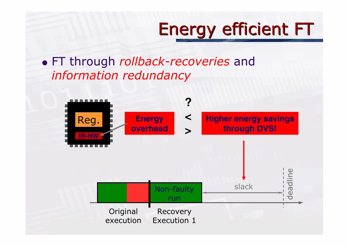
Energy efficient FTEnergy efficient FT
� FT through rollback-recoveries and information redundancy
� FT through rollback-recoveries and information redundancy
Reg.
IR-HW
Higher energy savings
through DVS!
Energy
overhead
?
<
>
Originalexecution
RecoveryExecution 1
deadline
Non-faultyrun
slack

Key observations Key observations
� Using various ITC benchmarks synthesized and analysed (hardware, energy) using EDA tools and
different fault rates
0It is possible to improve embedded computing systems reliability to transient faults without compromising energy saving through DVS
� Employ information redundancy for SEU and time redundancy for multiple SEU
� Adaptive Body Bias used to reduce leakage power also increases SEU rate by up to 36%

NetworkNetwork--onon--ChipChip
� Future embedded computing systems will contain hundred’s of processors and memories blocks
� Bus communication may prove to be system bottleneck because
0 shared bandwidth and not compatible with the required Gbits/s bandwidth requirements
0 limited opportunities for parallelism and not compatible with the highly parallel system architectures
0 not scalable
� Network-on-chip attempts to solve the above issues

NetworkNetwork--onon--Chip Chip

HW/SW CoHW/SW Co--Design with Design with NoCNoC Platform Platform
� Scheduling and mapping optimisation to include not only computation cost but also variable communication cost (power, latency, reliability,..) as there are a number of possible routing options in NoC
� NIRGAM SystemC cycle accurate simulator, analyse NoC in terms of routing algorithms and applications on various topologies.
http://nirgam.ecs.soton.ac.uk/

Final Thoughts Final Thoughts
� How to develop effective energy-efficient system-level automated design flows is reasonably well understood as demonstrated by the recent availability of SL-EDA tools
0 Extending SL flows to NoC platform is the next step?
� Low power and reliability are 2 key objectives when designing future embedded computing systems
0 Selecting the appropriate FT techniques fit for the application is important but not trivial
0 Developing application specific and *light weight* FT (employed only where needed) may be necessary to gain acceptance
