energy-efficient use of drives
TRANSCRIPT

102
© Carl Hanser Verlag, Munich Kunststoffe international 9/2019
EXTRUSION Energy Efficiency
[VEHICLE ENGINEERING] [MEDICAL TECHNOLOGY] [PACKAGING] [ELECTRICAL & ELECTRONICS] [CONSTRUCTION] [CONSUMER GOODS] [LEISURE & SPORTS] [OPTIC]
The extruder main drive often accounts for just a small por-tion of the overall purchase costs of an extruder [1]. However,
the operating costs of the machine give the main drive a much more important role in the selection process. Design and pro-curement must not just be based on the purchase price of the drive package, but crucially must also factor in the overall costs over the service life of the drive system.
Veka AG has been heavily involved in drive technology for decades. In the company’s experience, energy efficiency, the quality of the output signals, maintenance and wear exert do have a considerable influence on the economics of a drive sys-tem and the entire process. The company has also been stu-dying drive systems (Title figure) on test benches [2] since 2000, seeking to optimize the drives of the roughly 1000 twin and single screw extruders operated by the Veka Group worldwide. It has proved highly adept at this: the annual energy cost savings
accruing from the intensive studies are substantially greater than the overall expenditure on in-house construction and operation of the test benches.
Requirements Imposed on the Extruder Main Drive
Inside the processing unit, the task of the drive is to rotate the screw in the barrel. The drive system conveys the material, melts it, mixes it, homogenizes it and then discharges the polymer melt. The emerging hot, unstable profile is calibrated, cooled, drawn off and cut to length in the downstream equipment. This sequence of processes is matched to the instantaneous through-put of the extruder or die. It is therefore important that torque fluctuations in the process do not affect speed constancy. Fast, overshoot-free speed control for a setting range of 1 : 100 guaran-tees steady, constant throughput behavior (Table 1, p. 106).
Energy-Efficient Use of Drives
Process-Oriented Design of the Main Drive for the Extruder
Manufacturers of standard extruders sometimes incorporate oversized drives into their machine designs in
order to be able to cover a wide range of requirements. In times of high energy prices, however, this is no longer
economical. An extruder should be equipped with a drive package that is matched to the gearbox and the
processing unit. But what are the requirements governing the design of the drive system?
Drives on the test bench: this type of motor test bench is used by Veka to collect experience about the operation of some 700 twin-screw extruders
and 300 single-screw extruders used in production facilities worldwide at the most favorable operating point (© Veka)

103
Kunststoffe international 9/2019 www.kunststoffe-international.com
Energy Efficiency EXTRUSION
speed feedback. Speed deviations of less than 0.1 % are feasible and common.
Extruders tend to be used in continuous operation. High energy efficiency is therefore absolutely essential. To avoid over-heating, the motor must lend itself to continuous operation S1 (with constant load). For long uptimes, the drive should be a low-maintenance type and have a long service life.
The greatest weak points of the motor are the moving parts and the bearings. The bearings must be dimensioned to suit the type of load. For example, a double or reinforced bearing ar-rangement must be considered for operation under increased radial load, e. g. with a V-belt drive. Any expected bearing cur-rents, especially where EMC (electromagnetic compatibility) is poor, require measures to be taken, as this drastically shortens the bearing’s service life [4].
Normally, the space in the extruder is very cramped because it accommodates the gearbox, processing unit and control cabi-net. A compact design combined with high level protection
The only way to economically produce PVC profiles is to co-ordinate the extrusion process, the material and the die. Extru-sion depends first and foremost on defined plastification, good degassing and gentle build-up of the forming pressure. These points are essentially influenced by the motor-driven screw. A key parameter in this evaluation is the specific drive energy, which is the ratio of drive power (torque, revolution speed) to throughput. As a means of process control and evaluation, the exact speed and torque signals which are output by the fre-quency inverter prove to be essential variables.
If the motor delivers less torque than is indicated by the fre-quency inverter, an operating point close to the limit torque can, in certain circumstances, no longer be approached because the drive slows down.
Contrariwise, if the indicated torque is too low, the trans-mission and the processing unit may be overstressed too much. The deviation in torque should therefore not exceed 2 % [3]. Speed accuracy does not present a challenge in practice due to
100
%
90
85
80
75
70
65
600
Effici
ency
440 880 1320Speed
Three-phase shuntcommutator motor
rpm 2200 0 491 982 1473Speed
DC motor
rpm 2455 0 270 540 810Speed
Asynchronous motor
rpm 1350 0 500 1000 1500Speed
Synchronous motor
rpm 2500 0 522 1044 1566Speed
Reluctance motor
rpm 2610
ηrated = 80.9 % ηrated = 87.5 % ηrated = 90.2 % ηrated = 91.7 % ηrated = 93.0 %
Motor Inverter Total
Fig. 1. Efficiencies of the considered motor types at the rated point with a rated motor power of approx. 45 kW (source: Veka)
Fig. 2. Power flow of
the extruder main drive:
losses occur in the frequen-
cy inverter, motor and gear
(source: Veka)
Pv gear
Gear
MotorFrequency inverter/
electr. actuator
Mscrew
Mmotor
nmotor
nscrew
ioverall
Pout (mech.)
Pmotor (mech.) Pmotor (el.) Pin (el.)
Pv motor
Pv frequency inverter
© Kunststoffe
© Kunststoffe
»

104
© Carl Hanser Verlag, Munich Kunststoffe international 9/2019
EXTRUSION Energy Efficiency
nets require a small air gap between rotor and stator. This makes repair difficult and correspondingly costly.
The types of motor mentioned above are normally venti-lated internally. This offers benefits in terms of size, but comes at the price of a low protection level.
Asynchronous motors optimized for inverter operation are now established on the market. They offer a combination of good efficiency and relatively low acquisition costs. In the partial load range, they are less efficient than the synchronous types. This dis-advantage is virtually negated by clever design of the drive in the field weakening range (see Box p. 106) [3]. The external ventilation affords high level protection for the motor, but the motor is some-what larger than an internally ventilated synchronous type.
Currently gaining ground in drive technology is the reluc-tance motor, the stator of which is designed as a rotary phase machine. Instead of a squirrel cage rotor, it is equipped with a laminated rotor without windings. The motor functions purely on
Fig. 3. Field weakening range: while the motor power of a three-phase
asynchronous motor initially rises linearly with the speed when the
inverter is fed in, it remains constant from the rated frequency (fn)
onward. Above this, the previously constant torque drops slightly
(source: Westermann Tabellenbuch)
Anchor adjustment range
Characteristics of inverter feed
Field weakening range
Mn
Pn
0 fn
f, n
fmax
Fig. 4. Operating mode of the same motor with and without field
weakening with optimized overall ratio (source: [3])
Screw speed n
Motor speed (ioverall = 102.9)
Motor speed (ioverall = 136.7)
0
Mot
or p
ower
PM
; Mot
or to
rque
MM
Mot
or v
olta
ge U
M; M
otor
cur
rent
I M
2 4 6 8 10 12 14 16
0 250 500 750 1000 1250 1500 1750
0 332 664 996 1328 1660 1992 2324
IM
UM
PM
MM
The Authors Dieter Drescher is Head of Electrical Engineering at Veka AG in
Sendenhorst, Germany; [email protected]
Christian Angsmann is a Drive Testing Technician at Veka AG in
Sendenhorst; [email protected]
Company ProfileVeka AG, Sendenhorst, Germany, is the market leader in the produc-
tion of PVC profile systems for the manufacture of windows, doors
and roller shutters as well as PVC-U sheets. In addition to its head-
quarters, the Veka Group has 41 sites with a total of 24 production
plants and operates around 700 twin-screw extruders and 300 single-
screw extruders worldwide. The family-run group has sales in excess
of more than one billion euros. Worldwide, the company employs
around 6000 people on four continents, 1400 of them at the group’s
headquarters in Sendenhorst.
B www.veka.de
ServiceReferences & Digital VersionB You can find the list of references
and a PDF file of the article at www.kunststoffe-international.com/2019–09
German VersionB Read the German version of the
article in our magazine Kunststoffe or at www.kunststoffe.de
© Kunststoffe
© Kunststoffe
for the motor are also desirable, in view of the harsh conditions in the extrusion area. In order not to increase the noise level of the extruder line, steps are needed to ensure a low sound pressure level.
Properties of Different Motors
Calls for variable-speed drives for extruders over the decades have been met with several motors of different designs and properties. Early solutions include the three-phase shunt com-mutator motor and externally excited DC motor. The familiar advantages of the three-phase shunt commutator motor, namely mains operation, and the DC motor, namely precise, simple controllability, are offset by considerable disadvantages for both motor types. The machines are very energy-inefficient and very large compared to modern drive systems. Both types of motor utilize a commutator which is fed via sliding contacts, usually carbon brushes. The carbon brushes wear out and have to be serviced at regular intervals.
Thanks to advances in inverter technology, it has become possible to use synchronous motors in extrusion. These offer a compelling blend of high signal display accuracy and outstand-ing efficiency across the entire power range (Fig. 1). However, the rare earths built into the permanent magnets render them very expensive. Synchronous machines fitted with permanent mag-
105
Kunststoffe international 9/2019 www.kunststoffe-international.com
Energy Efficiency EXTRUSION
the reluctance principle, in which the magnetic field strives for the lowest magnetic resistance. The rotor aligns itself synchron-ously with the rotating field in the stator and torque is generated. Unlike the asynchronous motor, the reluctance motor generates no rotor losses arising from short-circuit currents in the cage. This increases its efficiency, especially under partial loads. Combined with the possibility of operation at 87 Hz (see Box p. 106), the out-come is a large power range with a relatively constant efficiency characteristic. The motor, which is suitable for frequency inverter operation only, requires neither rotary encoders nor forced venti-lation. This proves to be very beneficial to the purchase price. At present, the power factor (cos φ) is still somewhat poorer; often, it is necessary to select an inverter partial load one power step higher in order to provide the slightly higher apparent power.
A look at the history of drive types reveals two stand-out de-velopments in the area of ease of maintenance: the drives are becoming more efficient and the number of moving parts is de-creasing. Greater energy efficiency naturally leads to lower ener-gy costs, but it also directly impacts maintenance and wear. Greater efficiency gives rise to less power loss in the motor. The reduction in motor heating extends the service life of the bear-
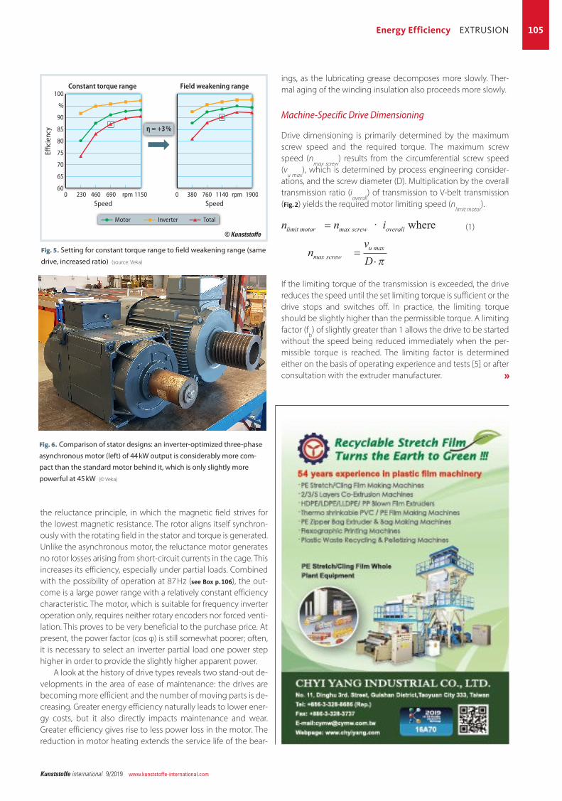
Fig. 5. Setting for constant torque range to field weakening range (same
drive, increased ratio) (source: Veka)
100
%
90
85
80
75
70
65
600
Effici
ency
230 460 690Speed
Constant torque range
rpm 1150 0 380 760 1140Speed
Field weakening range
rpm 1900
η = +3 %
Motor Inverter Total
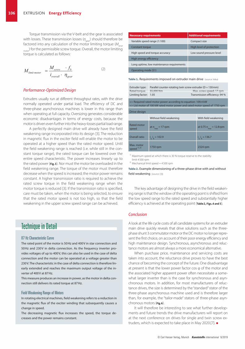
Fig. 6. Comparison of stator designs: an inverter-optimized three-phase
asynchronous motor (left) of 44 kW output is considerably more com-
pact than the standard motor behind it, which is only slightly more
powerful at 45 kW (© Veka)
© Kunststoffe
ings, as the lubricating grease decomposes more slowly. Ther-mal aging of the winding insulation also proceeds more slowly.
Machine-Specific Drive Dimensioning
Drive dimensioning is primarily determined by the maximum screw speed and the required torque. The maximum screw speed (n
max screw) results from the circumferential screw speed
(vu max
), which is determined by process engineering consider-ations, and the screw diameter (D). Multiplication by the overall transmission ratio (i
overall) of transmission to V-belt transmission
(Fig. 2) yields the required motor limiting speed (nlimit motor
).
(1)
If the limiting torque of the transmission is exceeded, the drive reduces the speed until the set limiting torque is sufficient or the drive stops and switches off. In practice, the limiting torque should be slightly higher than the permissible torque. A limiting factor (f
b) of slightly greater than 1 allows the drive to be started
without the speed being reduced immediately when the per-missible torque is reached. The limiting factor is determined either on the basis of operating experience and tests [5] or after consultation with the extruder manufacturer.
= i overalln n
nvD
limit motor screw
screwu=
⋅
max
maxmax
π
⋅ where
»
106
© Carl Hanser Verlag, Munich Kunststoffe international 9/2019
EXTRUSION Energy Efficiency
Torque transmission via the V-belt and the gear is associated with losses. These transmission losses (ηgear) should therefore be factored into any calculation of the motor limiting torque (Mlimit
motor) for the permissible screw torque. Overall, the motor limiting torque is calculated as follows:
(2)
Performance-Optimized Design
Extruders usually run at different throughput rates, with the drive normally operated under partial load. The efficiency of DC and three-phase asynchronous machines is lower in this range than when operating at full capacity. Oversizing generates considerable economic disadvantages in terms of energy costs, because the motor is driven even further into the heavy-losses partial load range.
A perfectly designed main drive will already have the field weakening range incorporated into its design [3]. The reduction in magnetic flux in the exciter field will enable the motor to be operated at a higher speed than the rated motor speed. Until the field weakening range is reached (i. e. while still in the con-stant torque range), the rated torque can be lowered over the entire speed characteristic. The power increases linearly up to the rated power (Fig. 3). Nor must the motor be overloaded in the field weakening range. The torque of the motor must therefore decrease when the speed is increased; the motor power remains constant. A higher transmission ratio is required to achieve the rated screw torque in the field weakening range when the motor torque is reduced [3]. If the transmission ratio is specified, care must be taken, when the motor is being selected, to ensure that the rated motor speed is not too high, so that the field weakening in the upper screw speed range can be achieved.
M M filimit motor
screw b
overall gear
=⋅
⋅ η
The key advantage of designing the drive in the field weaken-ing range is that the window of the operating point is shifted from the low speed range to the rated speed and substantially higher efficiency is achieved at the operating point (Table 2, Figs. 4 and 5).
Conclusion
A look at the life cycle costs of all candidate systems for an extruder main drive quickly reveals that drive solutions such as the three-phase shunt 3 commutator motor or the DC motor no longer repre-sent the first choice, on account of their poor energy efficiency and high maintenance design. Synchronous, asynchronous and reluc-tance motors are almost always a more economical alternative.
When purchase price, maintenance and servicing costs are taken into account, the reluctance drive proves to have the best chance of becoming the concept of the future. One disadvantage at present is that the lower power factor cos φ of the motor and the associated higher apparent power often necessitate a some-what larger inverter than is the case for synchronous and asyn-chronous motors. In addition, for most manufacturers of reluc-tance drives, the size is determined by the “standard” stator of the three-phase asynchronous machine used and is therefore larger than, for example, the “tailor-made” stators of three-phase asyn-chronous motors (Fig. 6).
It will therefore be interesting to see what further develop-ments and future trends the drive manufacturers will report on at the next conference on drives for single and twin screw ex-truders, which is expected to take place in May 2020.[7]. W
Technique in Detail87 Hz Characteristic CurveThe rated point of the motor is 50 Hz and 400 V in star connection and
50 Hz and 230 V in delta connection. As the frequency inverter pro-
vides voltages of up to 400 V, this can also be used in the case of delta
connection and the motor can be operated at a voltage greater than
230 V. The characteristic in the case of delta connection is therefore lin-
early extended and reaches the maximum output voltage of the in-
verter of 400 V at 87 Hz.
This measure produces an increase in power, as the motor in delta con-
nection still delivers its rated torque at 87 Hz.
Field Weakening Range of MotorsIn rotating electrical machines, field weakening refers to a reduction in
the magnetic flux of the exciter winding that subsequently causes a
change in speed.
The decreasing magnetic flux increases the speed, the torque de-
creases and the power remains constant.
Table 2. Example dimensioning of a three-phase drive with and without
field weakening (source: [3])
Necessary requirements
Variable speed range (1:100)
Constant torque
High speed and torque accuracy
High energy efficiency
Long uptime, low maintenance requirements
Operating mode (S1)
Additional requirements
Compact size
High level of protection
Low sound pressure level
Table 1. Requirements imposed on extruder main drive (source: Veka)
Extruder type:Rated torque:Limiting factor:
=> Required rated motor power according to equation: 109.4 kW=> List motor of 100 kW rated motor power and rated motor speed of 1750 rpm
Drive design
Rated motor speed
Overall ratio
Max. motor speed 1), 2)
1) Maximum speed at which there is 30 % torque reserve to the stability limit 4 500 rpm 2) Mechanical limit speed = 4 500 rpm
Parallel counter-rotating twin screw extruder (D ≈ 130 mm)55,000 Nm Max. screw speed: 17 rpm1.05 Transmission efficiency: 94 %
Without field weakening
at nmax
= 17 rpm
iG
iR = 102.9
1750 rpm
With field weakening
at 0.75 nmax
= 12.8 rpm
iG
iR = 136.7
2324 rpm