energy interactions with atmopshere and earth surface features
TRANSCRIPT

Interactions of energy with atmosphere & earth surface features
Agricultural College, Bapatla
Class seminar on
By M. Sunil Kumar BAD-14-06
1

– Propagates through the vacuum of space
– Interacts with the Earth's atmosphere & surface
– Reaches the remote sensor (interacts with various
optical systems, filters, emulsions, or detectors)
Electromagnetic energy interactions

Electromagnetic Radiation Models
WaveWave model model
ParticleParticle model model
An electromagnetic wave is composed of electric and magnetic An electromagnetic wave is composed of electric and magnetic vectors that are orthogonal to one another and travel from the vectors that are orthogonal to one another and travel from the source at the speed of light (3 x 10source at the speed of light (3 x 1088 m s m s-1-1))
Energy is transferred in discrete packets called quanta or photonsEnergy is transferred in discrete packets called quanta or photonsQ = hQ = h νν
Q = Energy of a quantum measured in Joules (J)Q = Energy of a quantum measured in Joules (J) h = Planck constant (6.626 x 10h = Planck constant (6.626 x 10⁻³⁴-34 J s J s-1-1)) ν ν = Frequency of the radiation= Frequency of the radiation

Energy interactions in the atmosphere
Refraction & transmission
Scattering
Absorption

Atmospheric Layers and ConstituentsMajor subdivisions of the atmosphere and the types of molecules and aerosols found in each layer.

1. Atmospheric refraction
θ 1
θ 2
θ 3
O ptically less dense atm osphere
O p tically m ore dense a tm osphere
O p tically less dense a tm osphere
P ath o f energy in
hom o geneous a tm osphere
3 n
n 1 = index o f re fraction for th is layer o f the a tm osphere
n 2
Inc iden t rad ian t energy
N orm al to the su rface
P ath o f rad ian t energy affected by a tm ospheric re fraction
A tm osp h eric R efraction
θ 1
θ 2
θ 3
O ptically less dense a tm osphere
O ptically m ore dense a tm osphere
O p tically less dense a tm osphere
P ath o f energy in
hom o geneous a tm osphere
3 n
n 1 = index o f re frac tion for th is layer o f the a tm osphere
n 2
Inciden t radian t energy
N orm al to the su rface
P ath o f rad ian t energy affected by atm ospheric re frac tion
A tm osp h eric R efraction Snell's law: The ratio of the sines of the angles of incidence and refraction is constant for all incidences in any given pair of media for electromagnetic waves of a definite frequency
The incident radiant energy is bent from its normal trajectory as it travels from one atmospheric layer to another. Snell's law (n1 sin θ1 = n2 sin θ2 = n3 sin θ3 ) can be used to predict how much bending will take place based on a knowledge of the angle of incidence and the optical density of each atmospheric level.
ni = c/ci
ni = index of refractionc = speed of light in a vacuumci = speed of light in a substance
Snell's law: The ratio of the sines of the angles of incidence and refraction is constant for all incidences in any given pair of media for electromagnetic waves of a definite frequency
The incident radiant energy is bent from its normal trajectory as it travels from one atmospheric layer to another. Snell's law (n1 sin θ1 = n2 sin θ2 = n3 sin θ3 ) can be used to predict how much bending will take place based on a knowledge of the angle of incidence and the optical density of each atmospheric level.
ni = c/ci
ni = index of refractionc = speed of light in a vacuumci = speed of light in a substance

Transmission The EMR varies along a frequency spectrum with infinite bounds The frequency range measurable and usable by remote sensors vary within
more than 9 orders of magnitude ~[0.1 mm – 100 m] The physical principles of interaction of the EMR with targets are different
over each spectral range. The human eye is generally sensitive between the [0.4-0.8] nm
range. The ultraviolet zone is mostly opaque, hence is generally unusable
for the RS applications There is no spectral window where the atmosphere is 100%
transparent The ionosphere is 100% opaque at frequencies below 10 Mhz

Atmospheric transmission
The atmosphere absorbs and scatters the EMR. Atmospheric opacity is largely due to absorption by molecules like H
20, O
2, O
3,
water etc Light is also scattered by the atmospheric molecules and particles

2. Scattering
Types of scattering
Rayleigh scattering
Mie scattering
Nonselective scattering
Deflection of a ray from a straight path

1. Rayleigh scattering Also called molecular
scattering; Consists of scattering from
atmospheric molecules; Dominant at elevations of 9 to
10 km above the surface; Follows a wavelength
dependency of ~ It is the Rayleigh scattering
that causes the blue color of the sky and the red color at sunset.

2. Mie scattering
• Particles' diameters are equivalent to
the wavelength d ≈ l
- Water vapor and dust are major causes
of Mie scattering
- Mie scattering tends to influence longer
wavelengths.
- It is common in lower atmosphere
where large particles are more
abundant, and dominates under
overcast could conditions.

3. Nonselective scattering
Particles are much larger than the wavelength d>>l
Water droplets (5-100 μm) and larger dust particles
Non-selective scattering is independent of wavelength
All wavelength are scattered equally (A could appears
white)
It scatters all visible and near to mid IR wavelengths.

Effects of scattering
• It causes haze in remotely sensed images
• It decreases the spatial detail on the images
• It also decreases the contrast of the images

3. Absorption• Absorption is the process by which radiant energy is absorbed and
converted into other forms of energy
• The atmosphere prevents, or strongly attenuates, transmission of
radiation through the atmosphere
• An absorption band is a range of wavelengths (or frequencies) in
the EMS within which radiant energy is absorbed by substances
such as water, CO2, O2, O3, & N2O.
• O3: absorbs ultraviolet radiation high in atmosphere
• CO2: absorbs mid and far infrared (13-17.5 μm) in lower
atmosphere
• H2O: absorbs mid-far infrared (5.5-7.0, >27 μm) in lower
atmosphere

Absorption bands

Absorption bands by different gases in different layers of atmosphere

Transmission, reflection, scattering, & absorption

Atmospheric windows (transmission bands )
The wavelength ranges in which the atmosphere is particularly transmissive
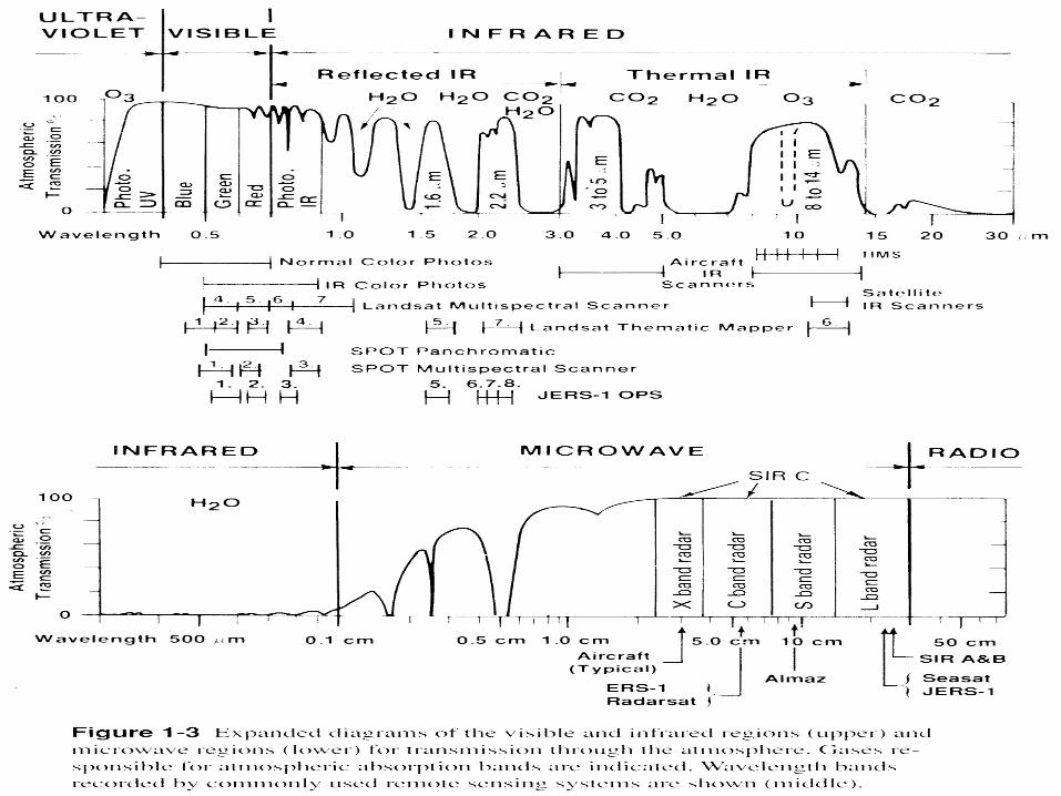

Atmospheric Windows • The windows:
UV & visible: 0.30-0.75 mm
Near infrared: 0.77-0.91 mm
Mid infrared: 1.55-1.75mm, 2.05-2.4 mm
Far infrared: 3.50-4.10 mm, 8.00- 9.20 mm, 10.2-12.4 mm
Microwave: 7.50-11.5 mm, 20.0+mm
• X-Rays and UV are very strongly absorbed and Gamma Rays
and IR are somewhat less strongly absorbed.
• The atmospheric windows are important for RS sensor design

Energy interactions with earth surface features

Energy Interactions with Earth Surface Features
• Reflection
• Absorption
• Transmission
• Emission

• All EM energy reaches earth's surface must be reflected, absorbed, or transmitted
• The proportion of each depends on:
– The spectral reflectance properties of the surface materials
– The surface smoothness relative to the radiation wavelength
–Wavelength
– Angle of illumination
Energy Interactions with Earth Surface Features

Energy Interactions with Earth Surface Features

- Light ray is redirected as it strikes a nontransparent surface
- Albedo - Spectral reflectance R (λ): the average amount of incident radiation reflected by an object at some wavelength interval
R (λ) = ER (λ) / EI (λ) x 100
Where
ER(λ) = reflected radiant energy
EI (λ) = incident radiant energy
1. Reflection

Specular versus diffuse reflectance
- Specular reflectors are flat surfaces that manifest mirrolike
reflections. The angle of reflection equals the angle of incident.
- Diffuse (or Lambertian) reflectors are rough surfaces that reflect
uniformly in all the directions
- If the surface is rough, the reflected rays go in many directions,
depending on the orientation of the smaller reflecting surfaces
- Diffuse contain spectral information on the color of the reflecting
surface, whereas specular reflections do not.
- In remote sensing we are often interested in measuring the diffuse
reflectance of objects.

Specular versus diffuse reflectance

Per cent reflection of earth surface features

2. Transmission
• Radiation passes through a substance without significant attenuation
• Transmittance (t):
transmitted radiation t = --------------------------- incident radiation

3. Absorption
Reflection + Transmission + Absorption = 100%

4. Emission

Spectral Characteristics of Features

Spectral reflectance curves for vegetation, soil, & water

Identification of Surface Materials Based on Spectral Reflectance

Spectra of vegetation• Chlorophyll absorbs blue and red, reflects green • Vegetation has a high reflection and transmission at NIR
wavelength range• Reflection or absorption at MIR range, the water
absorption bands•

Spectra of vegetation
Absorption is dominant process in visibleScattering is dominant process in near infraredWater absorption is increasingly important with increasing wavelength in the infrared.


Spectra of soil
What are the important properties of a soil in an RS image
-Soil texture (proportion of sand/silt/clay)
-Soil moisture content
-Organic matter content
-Mineral contents, including iron-oxide and carbonates
-Surface roughness

Dry soil spectrum
20
60
100
Percent Reflectance
0.5 0.7 1.1 1.30
Wavelength (µm)
80
40
0.9 1.5 1.7 1.9 2.1 2.3 2.5
Silt
Sand
10
30
50
70
90
• Coarse soil (dry) has relatively high reflectance• Increasing reflectance with increasing wavelength through the visible, near and mid infrared portions of the spectrum

Soil moisture and texture
• Soil moisture decreases reflectance
• Clays hold more water more ‘tightly’ than sand.
• Thus, clay spectra display more prominent water
absorption bands than sand spectra

Soil moisture and texture
20
60
Percent Reflectance
0.5 0.7 1.1 1.30
40
0.9 1.5 1.7 1.9 2.1 2.3 2.5
22 – 32%
10
30
50
Sand
20
60
0.5 0.7 1.1 1.30
Wavelength (µm)
40
0.9 1.5 1.7 1.9 2.1 2.3 2.5
35 – 40% 10
30
50 2 – 6%
0 – 4% moisture content
5 – 12%
Clay
a.
b.
Percent Reflectance
SandSandSand
ClayClayClay

Soil Organic Matter
Organic matter is a strong absorber of EMR, so more organic matter leads to darker soils (lower reflectance curves).

Iron Oxide
Recall that iron oxide causes a charge transfer absorption in the UV, blue and green wavelengths, and a crystal field absorption in the NIR (850 to 900 nm). Also, scattering in the red is higher than soils without iron oxide, leading to a red color.

Surface Roughness
• Smooth surface appears black.
• Smooth soil surfaces tend to be clayey or silty,
often are moist and may contain strong absorbers
such as organic content and iron oxide.
• Rough surface scatters EMR and thus appears
bright.

Spectra of water
• Transmission at visible bands and a strong absorption at NIR bands
• Water surface, suspended material, and bottom of water body can affect the spectral response

Thank You!